

ASUS M2NC61S User Manual
U2811
V-Series M2NC61S
ASUS PC (Desktop Barebone)
Installation Manual
Refer to the system user guide for installation details and other system
information from ASUS website.
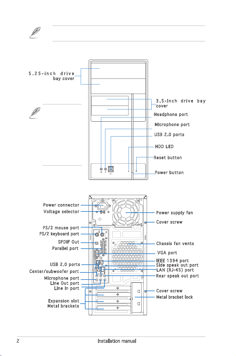
Front panel features
5 . 2 5 - i n c h d r i v e
bay cover
This V-series
provide V2/V3
two types of
front panel for
users to choose,
please refer to
your product
package for the
front panel type
you purchased.
Rear panel features
Power connector
Voltage selector
PS/2 mouse port
PS/2 keyb oard port
SPDIF Out
Parallel port
USB 2.0 ports
Center/subwoofer port
Microphone port
Line Out port
Line In port
Expansion slot
Metal brackets
3 . 5 - i n c h d r i v e b a y
cover
Headphone port
Microphone port
USB 2.0 ports
HDD LED
Reset button
Power button
Power supply fan
Cover screw
Chassis fan vents
VGA port
IEEE 1394 port
Side speak out port
LAN (RJ-45) port
Rear speak out port
Cover screw
Metal bracket lock
2 Installation manual
M2N-NM
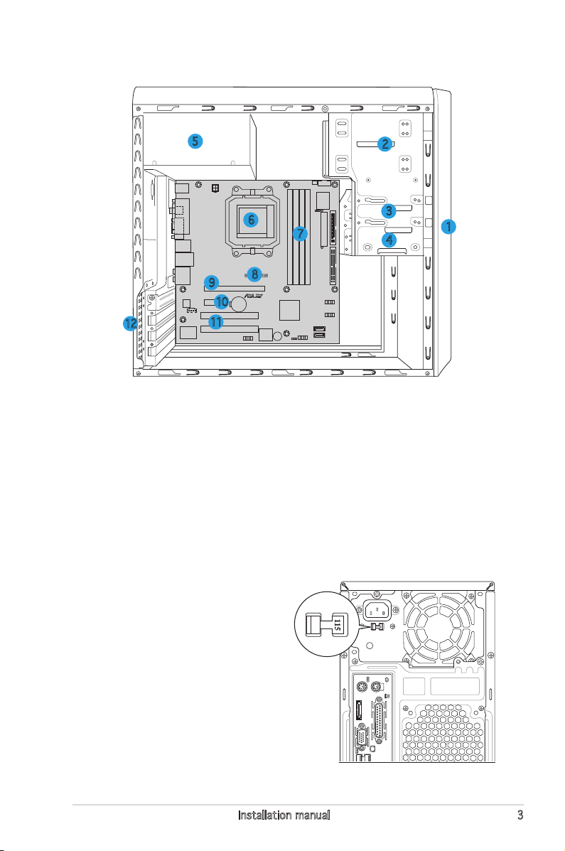
Internal components
eSATA
5
6
9
12
8
10
11
1. Front panel cover
2. 5.25-inch optical drive bays
3. Hard disk drive bay
4. Floppy disk drive bay
5. Power supply unit
6. CPU socket
7. DIMM sockets
2
3
7
4
8. ASUS motherboard
9. PCI Express x16 slot
10. PCI Express x1 slot
11. PCI slots
12. Metal bracket lock
1
Selecting the voltage
The system’s power supply unit has
a 115 V/230 V voltage selector
switch located beside the power
connector. Use this switch to select
the appropriate system input voltage
according to the voltage supply in your
area.
If the voltage supply in your area is
100-127 V, set the switch to 115 V.
If the voltage supply in your area is
200-240 V, set the switch to 230 V.
3Installation manual
 Loading...