


H87M-PLUS

Motherboard
H87M-PLUS

ii
E8528
Second Edition
July 2013
Copyright
©
2013 ASUSTeK COMPUTER INC. All Rights Reserved.
No part of this manual, including the products and software described in it, may be reproduced,
transmitted, transcribed, stored in a retrieval system, or translated into any language in any form or by any
means, except documentation kept by the purchaser for backup purposes, without the express written
permission of ASUSTeK COMPUTER INC. (“ASUS”).
Product warranty or service will not be extended if: (1) the product is repaired, modied or altered, unless
such repair, modication of alteration is authorized in writing by ASUS; or (2) the serial number of the
product is defaced or missing.
ASUS PROVIDES THIS MANUAL “AS IS” WITHOUT WARRANTY OF ANY KIND, EITHER EXPRESS
OR IMPLIED, INCLUDING BUT NOT LIMITED TO THE IMPLIED WARRANTIES OR CONDITIONS OF
MERCHANTABILITY OR FITNESS FOR A PARTICULAR PURPOSE. IN NO EVENT SHALL ASUS, ITS
DIRECTORS, OFFICERS, EMPLOYEES OR AGENTS BE LIABLE FOR ANY INDIRECT, SPECIAL,
INCIDENTAL, OR CONSEQUENTIAL DAMAGES (INCLUDING DAMAGES FOR LOSS OF PROFITS,
LOSS OF BUSINESS, LOSS OF USE OR DATA, INTERRUPTION OF BUSINESS AND THE LIKE),
EVEN IF ASUS HAS BEEN ADVISED OF THE POSSIBILITY OF SUCH DAMAGES ARISING FROM ANY
DEFECT OR ERROR IN THIS MANUAL OR PRODUCT.
SPECIFICATIONS AND INFORMATION CONTAINED IN THIS MANUAL ARE FURNISHED FOR
INFORMATIONAL USE ONLY, AND ARE SUBJECT TO CHANGE AT ANY TIME WITHOUT NOTICE,
AND SHOULD NOT BE CONSTRUED AS A COMMITMENT BY ASUS. ASUS ASSUMES NO
RESPONSIBILITY OR LIABILITY FOR ANY ERRORS OR INACCURACIES THAT MAY APPEAR IN THIS
MANUAL, INCLUDING THE PRODUCTS AND SOFTWARE DESCRIBED IN IT.
Products and corporate names appearing in this manual may or may not be registered trademarks or
copyrights of their respective companies, and are used only for identication or explanation and to the
owners’ benet, without intent to infringe.
Offer to Provide Source Code of Certain Software
This product contains copyrighted software that is licensed under the General Public License (“GPL”),
under the Lesser General Public License Version (“LGPL”) and/or other Free Open Source Software
Licenses. Such software in this product is distributed without any warranty to the extent permitted by the
applicable law. Copies of these licenses are included in this product.
Where the applicable license entitles you to the source code of such software and/or other additional data,
you may obtain it for a period of three years after our last shipment of the product, either
(1) for free by downloading it from http://support.asus.com/download
or
(2) for the cost of reproduction and shipment, which is dependent on the preferred carrier and the location
where you want to have it shipped to, by sending a request to:
ASUSTeK Computer Inc.
Legal Compliance Dept.
15 Li Te Rd.,
Beitou, Taipei 112
Taiwan
In your request please provide the name, model number and version, as stated in the About Box of the
product for which you wish to obtain the corresponding source code and your contact details so that we
can coordinate the terms and cost of shipment with you.
The source code will be distributed WITHOUT ANY WARRANTY and licensed under the same license as
the corresponding binary/object code.
This offer is valid to anyone in receipt of this information.
ASUSTeK is eager to duly provide complete source code as required under various Free Open Source
Software licenses. If however you encounter any problems in obtaining the full corresponding source
code we would be much obliged if you give us a notication to the email address gpl@asus.com, stating
the product and describing the problem (please DO NOT send large attachments such as source code
archives, etc. to this email address).

iii
Contents
Safety information ...................................................................................................... vi
About this guide ........................................................................................................ vii
H87M-PLUS specications summary ....................................................................... ix
Package contents ...................................................................................................... xii
Installation tools and components ......................................................................... xiii
Chapter 1: Product Introduction
1.1 Special features..........................................................................................1-1
1.1.1 Product highlights
........................................................................ 1-1
1.1.2 5X Protection
............................................................................... 1-2
1.1.3 ASUS Exclusive Features ...........................................................
1-3
1.1.4 ASUS Quiet Thermal Solution .....................................................
1-4
1.1.5 ASUS EZ DIY ..............................................................................
1-4
1.1.6 Other special features .................................................................
1-5
1.2 Motherboard overview ...............................................................................
1-5
1.2.1 Before you proceed .....................................................................
1-5
1.2.2 Motherboard layout .....................................................................
1-6
1.2.3 Central Processing Unit (CPU) ...................................................
1-8
1.2.4 System memory ..........................................................................
1-9
1.2.5 Expansion slots .........................................................................
1-11
1.2.6 Jumpers ....................................................................................
1-13
1.2.7 Onboard buttons and switches
.................................................. 1-14
1.2.8 Onboard LEDs ..........................................................................
1-15
1.2.9 Internal connectors
.................................................................... 1-16
Chapter 2: Basic installation
2.1 Building your PC system...........................................................................2-1
2.1.1 Motherboard installation ..............................................................
2-1
2.1.2 CPU installation
........................................................................... 2-3
2.1.3 CPU heatsink and fan assembly installation ...............................
2-4
2.1.4 DIMM installation
......................................................................... 2-6
2.1.5 ATX Power connection ................................................................
2-7
2.1.6 SATA device connection ..............................................................
2-8
2.1.7 Front I/O Connector ....................................................................
2-9
2.1.8 Expansion Card installation
....................................................... 2-10
2.2 Motherboard rear and audio connections .............................................
2-11
2.2.1 Rear I/O connection ..................................................................
2-11
2.2.2 Audio I/O connections ...............................................................
2-13
2.3 Starting up for the rst time ....................................................................
2-15

iv
2.4 Turning off the computer ......................................................................... 2-15
Chapter 3: BIOS setup
3.1 Knowing BIOS ............................................................................................3-1
3.2 BIOS setup program ..................................................................................
3-2
3.2.1 EZ Mode
...................................................................................... 3-3
3.2.2 Advanced Mode ..........................................................................
3-4
3.3 My Favorites ...............................................................................................
3-6
3.4 Main menu ..................................................................................................
3-7
3.5 Ai Tweaker menu ........................................................................................
3-9
3.6 Advanced menu .......................................................................................
3-21
3.6.1 CPU Conguration ....................................................................
3-22
3.6.2 PCH Conguration ....................................................................
3-24
3.6.3 SATA Conguration ...................................................................
3-26
3.6.4 System Agent Conguration
...................................................... 3-27
3.6.5 USB Conguration ....................................................................
3-29
3.6.6 Platform Misc Conguration ......................................................
3-30
3.6.7 Onboard Devices Conguration ................................................
3-30
3.6.8 APM ..........................................................................................
3-32
3.6.9 Network Stack ...........................................................................
3-33
3.7 Monitor menu ...........................................................................................
3-34
3.8 Boot menu ................................................................................................
3-37
3.9 Tools menu ...............................................................................................
3-43
3.9.1 ASUS EZ Flash 2 Utility ............................................................
3-43
3.9.2 ASUS O.C. Prole .....................................................................
3-43
3.9.3 ASUS SPD Information .............................................................
3-44
3.10 Exit menu ..................................................................................................
3-45
3.11 Updating BIOS ..........................................................................................
3-46
Chapter 4: Software support
4.1 Installing an operating system .................................................................4-1
4.2 Support DVD information ..........................................................................
4-1
4.2.1 Running the support DVD ...........................................................
4-1
4.2.2 Obtaining the software manuals
.................................................. 4-2
4.3 Software information .................................................................................
4-3
4.3.1 AI Suite 3
..................................................................................... 4-3
4.3.2 DIGI+ VRM ..................................................................................
4-5
4.3.3 EPU .............................................................................................
4-6
4.3.4 TurboV EVO ................................................................................
4-7

v
4.3.5 Fan Xpert 2 .................................................................................4-9
4.3.6 USB 3.0 Boost
........................................................................... 4-11
4.3.7 Network iControl
........................................................................ 4-12
4.3.8 EZ Update .................................................................................
4-13
4.3.9 System Information ...................................................................
4-13
4.3.10 Audio congurations
.................................................................. 4-15
Chapter 5: RAID support
5.1 RAID congurations ..................................................................................5-1
5.1.1 RAID denitions ..........................................................................
5-1
5.1.2 Installing Serial ATA hard disks ...................................................
5-2
5.1.3 Setting the RAID item in BIOS ....................................................
5-2
5.1.4 Intel
®
Rapid Storage Technology Option ROM utility ..................5-3
5.2 Creating a RAID driver disk
....................................................................... 5-7
5.2.1 Creating a RAID driver disk without entering the OS ..................
5-7
5.2.2 Creating a RAID driver disk in Windows
®
.................................... 5-8
5.2.3 Installing the RAID driver during Windows
®
OS installation ........ 5-8
Appendices
Notices .................................................................................................................... A-1
ASUS contact information ...................................................................................... A-3

vi
Safety information
Electrical safety
To prevent electrical shock hazard, disconnect the power cable from the electrical outlet
before relocating the system.
When adding or removing devices to or from the system, ensure that the power cables
for the devices are unplugged before the signal cables are connected. If possible,
disconnect all power cables from the existing system before you add a device.
Before connecting or removing signal cables from the motherboard, ensure that all
power cables are unplugged.
Seek professional assistance before using an adapter or extension cord. These devices
could interrupt the grounding circuit.
Ensure that your power supply is set to the correct voltage in your area. If you are not
sure about the voltage of the electrical outlet you are using, contact your local power
company.
If the power supply is broken, do not try to x it by yourself. Contact a qualied service
technician or your retailer.
Operation safety
Before installing the motherboard and adding devices on it, carefully read all the manuals
that came with the package.
Before using the product, ensure all cables are correctly connected and the power
cables are not damaged. If you detect any damage, contact your dealer immediately.
To avoid short circuits, keep paper clips, screws, and staples away from connectors,
slots, sockets and circuitry.
Avoid dust, humidity, and temperature extremes. Do not place the product in any area
where it may become wet.
Place the product on a stable surface.
If you encounter technical problems with the product, contact a qualied service
technician or your retailer.
•
•
•
•
•
•
•
•
•
•
•
•

vii
About this guide
This user guide contains the information you need when installing and conguring the
motherboard.
How this guide is organized
This guide contains the following parts:
• Chapter 1: Product introduction
This chapter describes the features of the motherboard and the new technology it
supports. It includes description of the switches, jumpers, and connectors on the
motherboard.
• Chapter 2: Basic installation
This chapter lists the hardware setup procedures that you have to perform when
installing system components.
• Chapter 3: BIOS setup
This chapter tells how to change system settings through the BIOS Setup menus.
Detailed descriptions of the BIOS parameters are also provided.
• Chapter 4: Software support
This chapter describes the contents of the support DVD that comes with the
motherboard package and the software.
• Chapter 5: RAID support
This chapter describes the RAID congurations.
Where to nd more information
Refer to the following sources for additional information and for product and software
updates.
1. ASUS websites
The ASUS website provides updated information on ASUS hardware and software
products. Refer to the ASUS contact information.
2. Optional documentation
Your product package may include optional documentation, such as warranty yers,
that may have been added by your dealer. These documents are not part of the
standard package.

viii
Conventions used in this guide
To ensure that you perform certain tasks properly, take note of the following symbols used
throughout this manual.
DANGER/WARNING: Information to prevent injury to yourself when trying to
complete a task.
CAUTION: Information to prevent damage to the components when trying to
complete a task
IMPORTANT: Instructions that you MUST follow to complete a task.
NOTE: Tips and additional information to help you complete a task.
Typography
Bold text Indicates a menu or an item to select.
Italics
Used to emphasize a word or a phrase.
<Key> Keys enclosed in the less-than and greater-than sign
means that you must press the enclosed key.
Example: <Enter> means that you must press the Enter or
Return key.
<Key1> + <Key2> + <Key3> If you must press two or more keys simultaneously, the key
names are linked with a plus sign (+).
ix
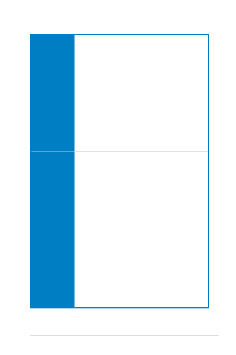
H87M-PLUS specications summary
CPU LGA1150 socket for the 4th Generation Intel
®
Core™ i7/ i5 / i3, Pentium
®
,
and Celeron
®
processors
Supports 22nm CPU
Supports Intel
®
Turbo Boost Technology 2.0*
* The Intel
®
Turbo Boost Technology 2.0 support depends on the CPU types.
** Refer to
www.asus.com for Intel
®
CPU support list.
Chipset Intel
®
H87 Express Chipset
Memory 4 x DIMMs, max. 32GB, DDR3 1600 / 1333 /1066MHz, non-ECC, un-
buffered memory
Dual-channel memory architecture
Supports Intel
®
Extreme Memory Prole (XMP)
* Hyper DIMM support is subject to the physical characteristics of individual
CPUs. Some hyper DIMMs only support one DIMM per channel. Please refer to
Memory QVL (Qualied Vendors List) for details.
** Due to Intel
®
chipset limitation, the DDR3 1600MHz and higher memory modules
on XMP mode will run at the maximum transfer rate of DDR3 1600MHz.
*** Refer to
www.asus.com or this user manual for the Memory QVL (Qualied
Vendors List).
Expansion slots 1 x PCI Express 3.0/2.0 x16 slot [yellow] (at x16 mode)
1 x PCI Express 2.0 x16 slot [dark brown] (at x4 mode, compatible with
PCIe x1, and x4 devices)
2 x PCI slots
VGA Integrated Graphics Processor - Intel
®
HD Graphics support
Multi-VGA output support: HDMI / DVI / RGB port
Supports HDMI with max. resolution of 4096 x 2160 @24Hz / 2560 x 1600
@60Hz
Supports DVI with max. resolution of 1920 x 1200 @60Hz
Supports RGB with max. resolution of 1920 x 1200 @60Hz
Maximum shared memory 1024MB
Multi-GPU support Supports AMD
®
CrossFireX™ Technology
Storage
Intel
®
H87 Express Chipset with RAID 0, 1, 5, 10 and Intel
®
Rapid Storage Technology 12 support
- 6 x SATA 6.0 Gb/s ports (yellow)
- Supports Intel
®
Smart Response Technology, Intel
®
Rapid Start
Technology, and Intel
®
Smart Connect Technology*
* These functions will work depending on the CPU installed.
LAN Realtek
®
8111G Gigabit LAN controller
Audio Realtek
®
ALC887 8-channel high denition audio CODEC
- Supports Jack-Detection, multi-streaming and front panel jack-
retasking
* Use a chassis HD audio module in the front panel to support 8-channel audio
output
(continued on the next page)

x
USB
Intel
®
H87 Express Chipset - supports ASUS USB 3.0 Boost
- 2 x USB 3.0/2.0 ports at mid-board for front panel support
- 4 x USB 3.0/2.0 ports at rear panel (blue)
- 8 x USB 2.0/1.1 ports (6 ports at mid-board, 2 ports at rear panel)
ASUS unique
features
ASUS 5X Protection
- ASUS motherboards safeguard your PC with 5X Protection: DIGI+VRM,
DRAM Fuse, ESD Guards, High-Quality 5K Solid Capacitors, and Stainless
Steel Back I/O to ensure the best quality, reliability, and durability
ASUS DIGI+ VRM
- ASUS DIGI+ VRM: Digital Power Design for the CPU and iGPU
- ASUS 4 Phase Power Design
ASUS Fuse Protection
- Enhanced DRAM overcurrent protection and short circuit damage protection.
ASUS ESD Guards
- Enhanced ESD protection for extended component lifespan.
ASUS High-Quality 5K Solid Capacitors
- 2.5x Long Lifespan with excellent durability
ASUS Extra Durable Stainless Steel Back I/O
- 3 x More durable corrosion-resistant coating.
ASUS Exclusive Features
- ASUS EPU
- ASUS Network iControl* featuring instant network bandwidth domination for
top network program in use
- ASUS USB 3.0 Boost
- AI Charger
- ASUS GPU Boost
- ASUS MemOK!
- AI Suite 3
- Anti Surge protection
ASUS Q-Design
- ASUS Q-Slot
- ASUS Q-DIMM
ASUS Quiet Thermal Solution
- ASUS Fanless Design: Stylish Heatsink
- ASUS Fan Xpert 2 featuring Fan Auto Tuning function for optimized speed
control, providing an exclusive tailored fan speed setting for each fan
ASUS EZ DIY
- ASUS UEFI BIOS EZ Mode featuring friendly graphics user interface
- ASUS CrashFree BIOS 3
- ASUS EZ Flash 2
* The ASUS Network iControl feature does not support Windows
®
XP/Vista operating
systems.
(continued on the next page)
H87M-PLUS specications summary
xi
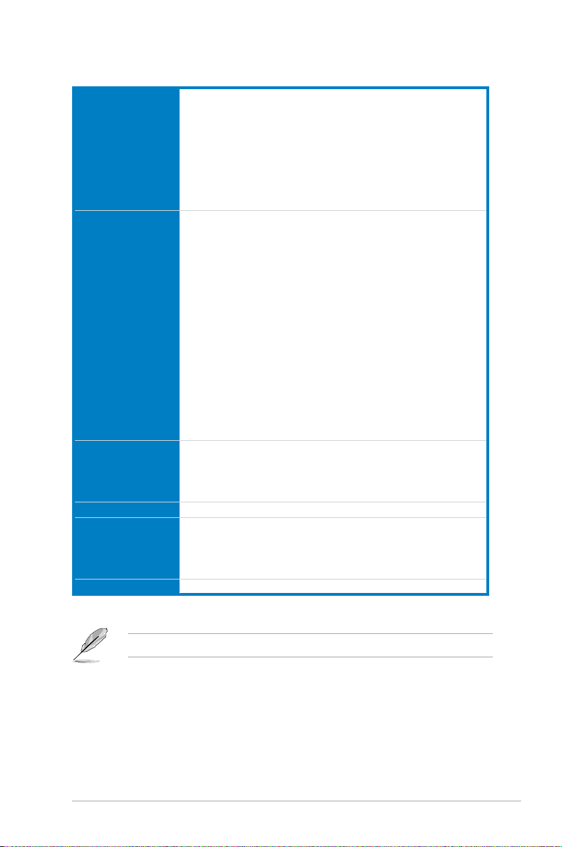
Back Panel I/O
Ports
1 x PS/2 mouse / keyboard combo port
1 x HDMI port
1 x DVI-D port
1 x RGB port
1 x LAN (RJ-45) port
4 x USB 3.0/2.0 ports
2 x USB 2.0/1.1 ports
3 x audio jacks support 8-channel
Internal I/O
connectors
1 x 19-pin USB 3.0/2.0 connector supports additional 2 USB 3.0/2.0 ports
3 x USB 2.0/1.1 connectors support additional 6 USB 2.0/1.1 ports
6 x SATA 6.0 Gb/s connectors
1 x 4-pin CPU Fan connector
2 x 4-pin Chassis Fan connectors
1 x Front panel audio connector (AAFP)
1 x S/PDIF out header
1 x 24-pin EATX Power connector
1 x 8-pin EATX 12V Power connector
1 x MemOK! button
1 x LPT button
1 x System Panel
1 x Clear CMOS jumper
1 x TPM header
1 x COM port
BIOS features 64 Mb Flash ROM, UEFI AMI BIOS, Green, PnP, DMI 2.0, WfM 2.0, SM
BIOS 2.7, ACPI 2.0a, Multi-language BIOS, ASUS EZ Flash 2, ASUS
CrashFree BIOS 3, F3 Shortcut function, My Favorites, Quick Note, Last
Modied Log, F12 PrintScreen function, and ASUS DRAM SPD (Serial
Presence Detect) memory information
Manageability WfM 2.0, DMI 2.0, WOL by PME, WOR by PME, PXE
Support DVD
contents
Drivers
ASUS Utilities
EZ Update
Anti-virus software (OEM version)
Form factor uATX form factor: 9.6 in. x 8.6 in. (24.4 cm x 21.9 cm)
H87M-PLUS specications summary
Specications are subject to change without notice.
xii
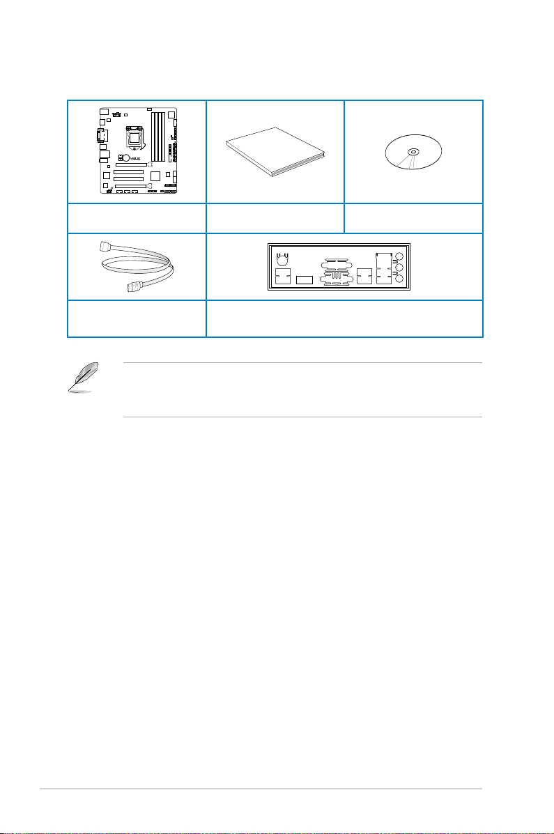
• If any of the above items is damaged or missing, contact your retailer.
• The illustrations above are for reference only. Actual product specications may vary
with different models.
H87M-PLUS
User Manual
ASUS H87M-PLUS motherboard
User manual Support DVD
2 x Serial ATA 6.0 Gb/s cables 1 x ASUS I/O shield
Package contents
Check your motherboard package for the following items
xiii
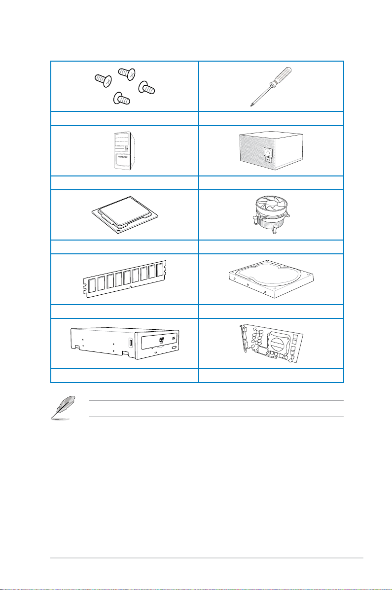
Installation tools and components
1 bag of screws Philips (cross) screwdriver
PC chassis Power supply unit
Intel
®
LGA1150 CPU Intel
®
LGA1150 compatible CPU Fan
DIMM SATA hard disk drive
SATA optical disc drive (optional) Graphics card (optional)
The tools and components in the table above are not included in the motherboard package.

xiv

ASUS H87M-PLUS
1-1
Chapter 1
Product introduction
1
1.1 Special features
1.1.1 Product highlights
LGA1150 socket for 4th Generation Intel
®
Core™ i7, Intel
®
Core™ i5, Intel
®
Core™ i3, Pentium
®
, and Celeron
®
Processors
This motherboard supports Intel
®
4
th
generation Core i7/i5/i3, Pentium
®
, and Celeron
®
processors in the LGA1150 package. It provides great graphics and system performance with
its GPU, dual-channel DDR3 memory slots, and PCI Express 2.0/3.0 expansion slots.
Intel
®
H87 Express Chipset
Intel
®
H87 Express Chipset is a single-chipset that supports the 1150 socket 4th generation
Intel
®
Core™ i7, Intel
®
Core™ i5, Intel
®
Core™ i3, Pentium
®
and Celeron
®
processors. It
utilizes the serial point-to-point links, which increases bandwidth and enhances the system’s
performance. It natively supports up to six USB 3.0 ports for up to ten times faster transfer
rate than USB 2.0 and enables the iGPU function for Intel
®
integrated graphics performance.
PCI Express
®
3.0
PCI Express
®
3.0 (PCIe 3.0) is the PCI Express bus standard that provides twice the
performance and speed of PCIe 2.0. It provides an optimal graphics performance,
unprecedented data speed, and seamless transition with its complete backward compatibility
to PCIe 1.0/2.0 devices.
Dual-Channel DDR3 1600 / 1333 /1066MHz Support
The motherboard supports the dual-channel DDR3 memory that features data transfer rates
of DDR3 1600 / 1333 /1066MHz to boost the system’s performance, and to meet the higher
bandwidth requirements of 3D graphics, multimedia and Internet applications.
* Hyper DIMM support is subject to the physical characteristics of individual CPUs. Some hyper DIMMs only
support one DIMM per channel.
** Due to Intel
®
chipset limitation, DDR3 1600MHz and higher memory modules on XMP mode will run at the
maximum transfer rate of DDR3 1600MHz.
*** Refer to www.asus.com or this user manual for the Memory QVL (Qualied Vendors List)
Intel
®
Smart Response Technology
Intel
®
Smart Response Technology, an important part of Green ASUS eco-friendly computing,
reduces load and wait time, eliminates unecessary hard drive spin thus lowering power
usage, and uses an installed SSD (requires 18.6 GB available space) as a cache for
frequently accessed data or applications. It combines SSD performance and hard drive
capacity, operating up to six times faster than a hard-drive-only system to boost the system’s
overall performance.
* 4th generation Intel
®
Core™ processors support Intel® Smart Response Technology.
** An operating system must be installed on the HDD to launch Intel® Smart Response Technology.
*** The SSD is reserved for caching function.
Chapter 1: Product Introduction

1-2
Chapter 1: Product introduction
Chapter 1
Quad-GPU CrossFireX™ Support
This motherboard features the most powerful Intel
®
H87 platform that optimizes PCIe
allocation in multi-GPU CrossFireX™ solution, giving you a brand-new gaming enjoyment.
Intel
®
Smart Connect Technology
Intel® Smart Connect Technology allows your system to receive updates for your web
applications in real-time even when your system is in sleep mode. This saves wait time for
applications to update and sync with the cloud for a more efcient computing experience.
Intel
®
Rapid Start Technology
Intel® Rapid Start Technology allows your computer to quickly resume from a low-power
hibernate state in seconds. Saving your system memory to the designated SSD, it provides
your computer a faster wake-up response time, while still keeping the energy use low.
1.1.2 5X Protection
5X Protection
ASUS motherboard guards your PC with 5X PROTECTION. We use components like
ESD uits tested to strict standards that elimiinate electrostatic interference, polyswitches
(resettable fuses) around DRAM slots to prevent overcurrent and short-circuit damage, and
a corrosion-resistant back I/O shield. All examples of ASUS providing the best possible
reliability and durability.
DIGI+VRM
Voltage regulator modules (VRMs) are among the most essential motherboard components.
A good VRM intelligently delivers CPU power based on actual needs at any given time.
Quickly-changing digital signal (SVID) requests from the CPU may prove too much for
generic VRMs, and ASUS was rst with digital controllers featuring faster sensing and
respnse to deliver precise CPU power on demand. This great accuracy reduces energy
waste and improves system stability.
ASUS DRAM Fuse
Onboard polyswitch (resettable fuse) prevents overcurrent and short-circuit damage. This
extends beyond I/O ports to DRAM to safeguard the system and device lifespan.
ASUS ESD Guards
Electrostatic discharges (ESD) can happen suddenly, and their damaging effects are often
underestimated. ASUS ESD Guards offer an active protective circuit design that ensures
electrostatic discharges are properly grounded, providing prolonged component longevity.
ASUS High-Quality 5K Solid Capacitors
ASUS high-quality solid state capacitors assure a 5000-hour lifespan - equivalent to 2.5 times
longer than traditional capacitors. All capacitors pass testing under temperatures as high
as 105 degrees and meet Japanese industrial standards to provide excellent durability and
ehanced thermal capacity.

ASUS H87M-PLUS
1-3
Chapter 1
ASUS Stainless Steel Back I/O
ASUS motherboard back I/O panels are made from strong and corrosion-resistant stainless
steel, which is bonded with a thin layer of chromium oxide to enhance anti-corrosive
properties. Passing 72-hour spray salt endurance tests, ASUS stainless steel back I/O panels
have a usage life three times longer compared to ordinary panels.
1.1.3 ASUS Exclusive Features
ASUS EPU
Tap into the world’s rst real-time PC power saving chip through a simple onboard switch or
Ai Suite II utility. Get total system-wide energy optimization by automatically detecting current
PC loadings and intelligently moderating power consumption. This also reduces fan noise
and extends component longevity.
GPU Boost
GPU Boost accelerates the integrated GPU for extreme graphics performance, facilitates
exible frequency adjustments, and easily delivers stable system-level upgrades for every
use.
USB 3.0 Boost
ASUS USB 3.0 Boost, which supports USB 3.0 standard UASP (USB Attached SCSI
Protocol), signicantly increases a USB device’s transfer speed up to 170% faster than the
already impressive USB3.0 transfer speed. It automatically accelerates data speeds for
compatible USB 3.0 peripherals without the need for any user interaction.
Network iControl
Network iControl is an intuitive one-step network control center that makes it easier for you to
manage your bandwidth and allows you to set, monitor, and schedule the bandwidth priorities
for your network programs. It allows you to automatically connect to a PPPoE network for a
more convenient online experience.

1-4
Chapter 1: Product introduction
Chapter 1
MemOK!
MemOK!, the remarkable memory rescue tool, allows you to simply press a button to
patch memory issues, ensure memory boot compatibility, determine fail-safe settings, and
dramatically improve the system’s bootup.
AI Suite 3
With its user-friendly interface, ASUS AI Suite 3 integrates several ASUS utilities and
allows you to launch and operate these utilities simultaneously. It allows you to congure
the overclocking settings, adjust the frequencies and related voltages, remotely control the
system via a mobile device, and other easy-to-use and helpful utilities.
ASUS Anti-Surge Protection
This special design protects expensive devices and the motherboard from damage caused
by power surges from switching power supply unit (PSU).
1.1.4 ASUS Quiet Thermal Solution
ASUS Fanless Design - Heat-pipe solution
The stylish heatsink features a 0-dB thermal solution that offers you a noiseless PC
environment. The heatsink design also lowers the temperature of the chipset and power
phase area through high efcient heat-exchange. Combined with usability and aesthetics,
the ASUS stylish heatsink will give you an extremely silent and cooling experience with its
elegant appearance.
ASUS Fan Xpert 2
ASUS Fan Xpert 2 provides customizable settings for a cooler and quieter computing
environment. With its Fan Auto Tuning feature, ASUS Fan Xpert 2 automatically detects
and tweaks all fan speeds, and provides you with optimized fan settings based on the fans’
specications and positions.
1.1.5 ASUS EZ DIY
ASUS UEFI BIOS
ASUS UEFI BIOS, a UEFI compliant architecture, offers the rst mouse-controlled intuitive
graphical BIOS interface that goes beyond the traditional keyboard-only BIOS controls,
providing you with more exibility, convenience, and easy to navigate UEFI BIOS than the
traditional BIOS versions. It offers you with dual selectable modes and native support for hard
drives larger than 2.2 TB.
ASUS UEFI BIOS includes the following new features:
• New My Favorite function allows you to quickly access the frequently used items
• New Quick Note function allows you to take notes in the BIOS environment
• New log reminder allows you to view all your modied settings

ASUS H87M-PLUS
1-5
Chapter 1
• F12 BIOS snapshot hotkey
• F3 Shortcut for most accessed information
• ASUS DRAM SPD (Serial Presence Detect) information detecting faulty DIMMs, and
helping with difcult POST situations.
ASUS Q-Design
ASUS Q-Design enhances your DIY experience. All of Q-Slot and Q-DIMM design speed up
and simplify the DIY process.
1.1.6 Other special features
HDMI Support
High Denition Multimedia Surface (HDMI) is a set of digital video standards that delivers
multi-channel audio and uncompressed digital video for full HD 1080p visuals through a
single cable. Supporting HDCP copy protection such as HD DVD and blu-ray discs, HDMI
provides you with the highest quality home theater experience.
ErP Ready
The motherboard is European Union’s Energy-related Products (ErP) ready, and ErP requires
products to meet certain energy efciency requirement in regards to energy consumptions.
This is in line with ASUS vision of creating environment-friendly and energy-efcient products
through product design and innovation to reduce carbon footprint of the product and thus
mitigate environmental impacts.
1.2 Motherboard overview
1.2.1 Before you proceed
Take note of the following precautions before you install motherboard components or change
any motherboard settings.
• Unplug the power cord from the wall socket before touching any component.
• Before handling components, use a grounded wrist strap or touch a safely grounded
object or a metal object, such as the power supply case, to avoid damaging them due
to static electricity.
• Hold components by the edges to avoid touching the ICs on them.
• Whenever you uninstall any component, place it on a grounded antistatic pad or in the
bag that came with the component.
• Before you install or remove any component, ensure that the ATX power supply is
switched off or the power cord is detached from the power supply. Failure to do so
may cause severe damage to the motherboard, peripherals, or components.
1-6
Chapter 1: Product introduction
Chapter 1
Refer to 1.2.9 Internal connectors and 2.2.1 Rear I/O connection for more information
about rear panel connectors and internal connectors.
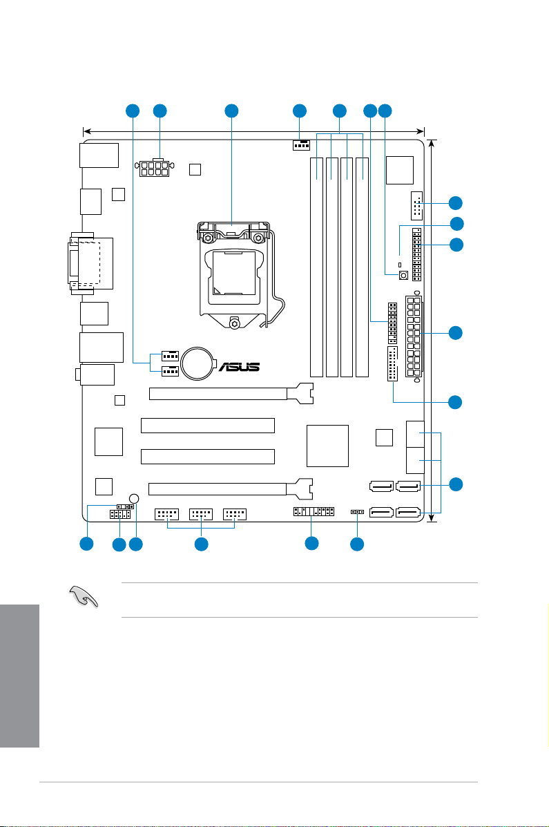
1.2.2 Motherboard layout
H87M-PLUS
PCIEX16_1
PCIEX16_2
PCI1
PCI2
RTL
8111G
ASM
1442
USB910 USB1112 USB1314
AAFP
EATXPWR
CPU_FAN
BATTERY
Super
I/O
ALC
887
ASM
1083
KBMS_USB78
DVI_VGA
8MB
BIOS
SB_PWR
CLRTC
21.9cm(8.6in)
DDR3 DIMM_A1 (64bit, 240-pin module)
DDR3 DIMM_A2 (64bit, 240-pin module)
DDR3 DIMM_B1 (64bit, 240-pin module)
DDR3 DIMM_B2 (64bit, 240-pin module)
PANEL
SATA6G_1SATA6G_2
SATA6G_3 SATA6G_4
SATA6G_5 SATA6G_6
AUDIO
LAN_USB3_34
USB3_56
HDMI
CHA_FAN2
CHA_FAN1
SPDIF_OUT
24.4cm(9.6in)
DRAM_LED
MemOK!
LGA1150
DIGI
+VRM
COM
EATX12V
USB3_12
TPM
LPT
Intel
®
H87
21 3 41 65
1215
11
13
14
16
8
7
2
9
10
17
ASUS H87M-PLUS
1-7
Chapter 1
Layout contents
Connectors/Jumpers/Slots Page
1. CPU and chassis fan connectors (4-pin CPU_FAN, 4-pin CHA_FAN1/2) 1-19
2. ATX power connectors (24-pin EATXPWR, 8-pin EATX12V)
1-20
3. LGA1150 CPU socket
1-8
4. DDR3 DIMM slots
1-9
5. TPM header (20-1 pin TPM)
1-20
6. MemOK! button
1-14
7. Serial port connector (10-1 pin COM)
1-17
8. DRAM LED (DRAM_LED)
1-15
9. LPT connector (26-1 pin LPT)
1-16
10. USB 3.0 connector (20-1 pin USB3_12)
1-17
11. Intel
®
H87 Serial ATA 6.0 Gb/s connectors (7-pin SATA6G_1-6) 1-16
12. Clear RTC RAM (3-pin CLRTC)
1-13
13. System panel connector (20-8 pin PANEL)
1-21
14. USB 2.0 connectors (10-1 pin USB910, USB1112, USB1314)
1-18
15. Standby power LED (SB_PWR)
1-15
16. Front panel audio connector (10-1 pin AAFP)
1-19
17. Digital audio connector (4-1 pin SPDIF_OUT)
1-18
1-8
Chapter 1: Product introduction
Chapter 1
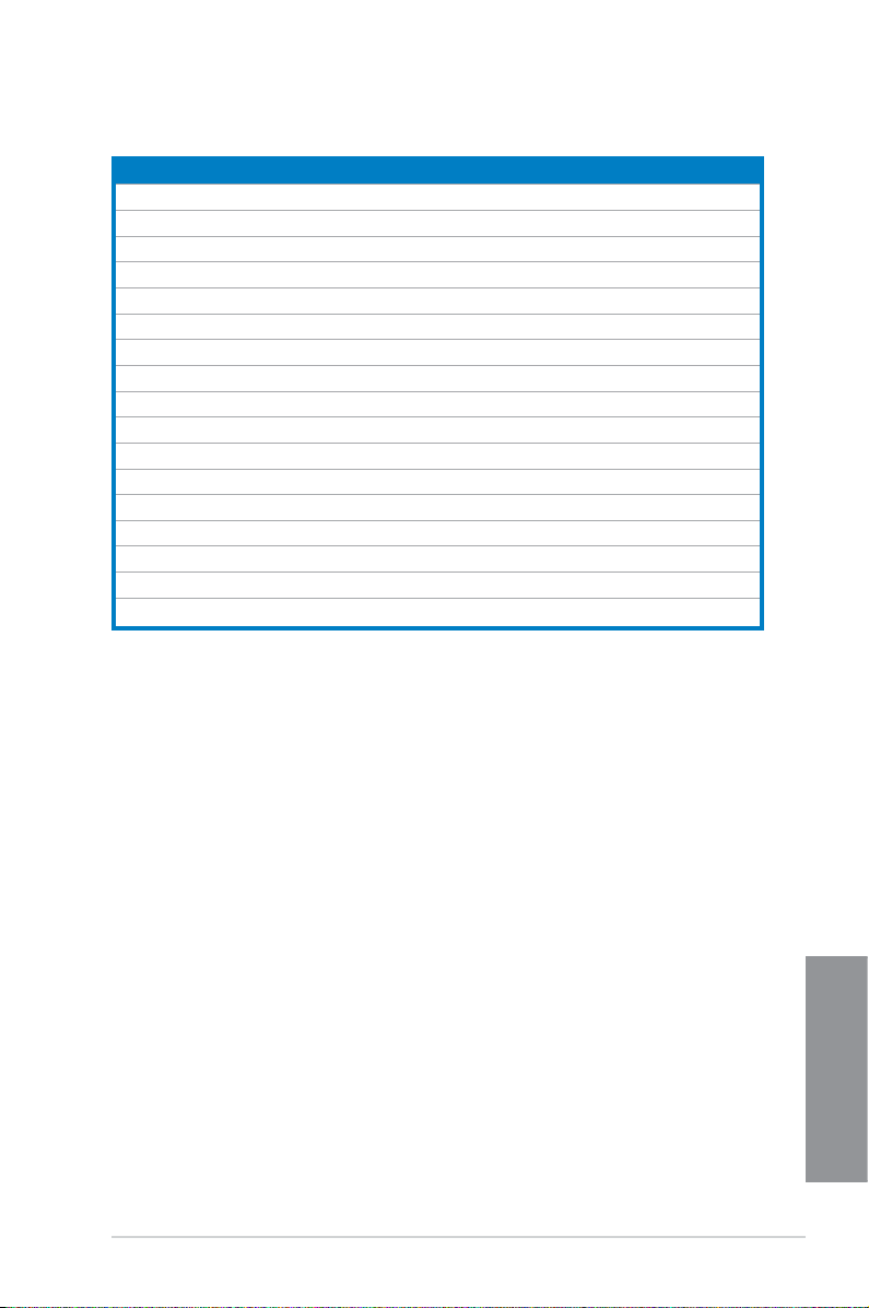
1.2.3 Central Processing Unit (CPU)
The motherboard comes with a surface mount LGA1150 socket designed for the 4th
Generation Intel
®
Core™ i7, Intel
®
Core™ i5, Intel
®
Core™ i3, Pentium™, and Celeron™
processors.
• Ensure that all power cables are unplugged before installing the CPU.
• Ensure that you install the correct CPU designed for LGA1150 only. DO NOT install a
CPU designed for LGA1155 and LGA1156 sockets on the LGA1150 socket.
• Upon purchase of the motherboard, ensure that the PnP cap is on the socket and
the socket contacts are not bent. Contact your retailer immediately if the PnP cap
is missing, or if you see any damage to the PnP cap/socket contacts/motherboard
components. ASUS will shoulder the cost of repair only if the damage is shipment/
transit-related.
• Keep the cap after installing the motherboard. ASUS will process Return Merchandise
Authorization (RMA) requests only if the motherboard comes with the cap on the
LGA1150 socket.
• The product warranty does not cover damage to the socket contacts resulting from
incorrect CPU installation/removal, or misplacement/loss/incorrect removal of the PnP
cap.
H87M-PLUS
H87M-PLUS CPU socket LGA1150
ASUS H87M-PLUS
1-9
Chapter 1
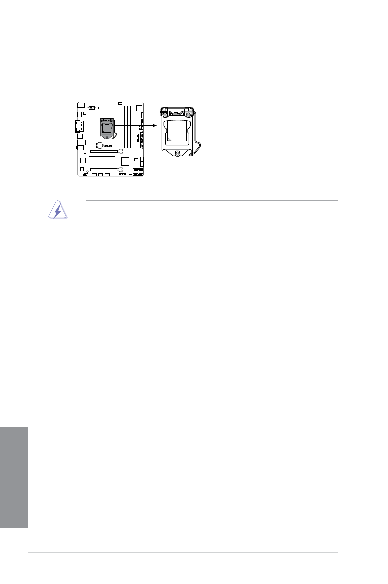
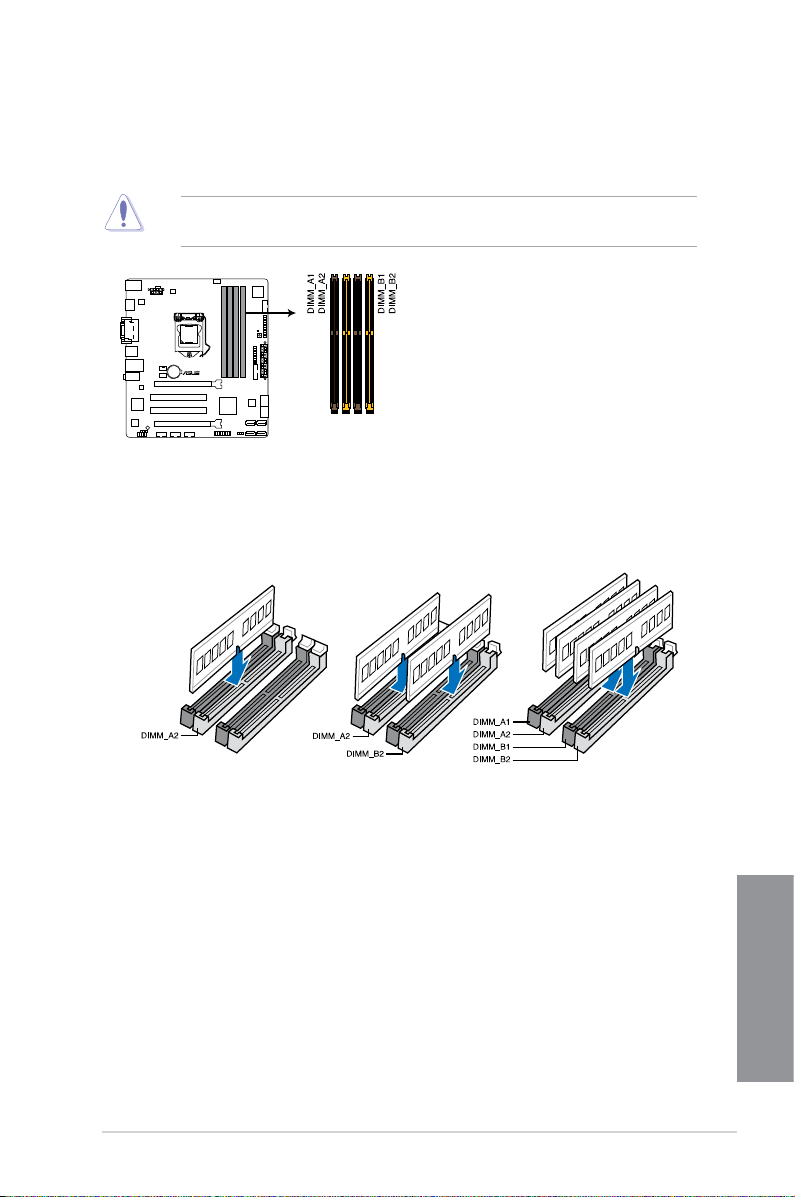
Recommended memory congurations
1.2.4 System memory
The motherboard comes with four Double Data Rate 3 (DDR3) Dual Inline Memory Modules
(DIMM) slots.
A DDR3 module is notched differently from a DDR or DDR2 module. DO NOT install a DDR
or DDR2 memory module to the DDR3 slot.
H87M-PLUS
H87M-PLUS 240-pin DDR3 DIMM sockets

1-10
Chapter 1: Product introduction
Chapter 1
Memory congurations
You may install 1GB, 2GB, 4GB, and 8GB unbuffered and non-ECC DDR3 DIMMs into the
DIMM sockets.
• You may install varying memory sizes in Channel A and Channel B. The system maps
the total size of the lower-sized channel for the dual-channel conguration. Any excess
memory from the higher-sized channel is then mapped for single-channel operation.
• Due to Intel
®
chipset limitation, DDR3 1600MHz and higher memory modules on XMP
mode will run at the maximum transfer rate of DDR3 1600MHz.
• According to Intel CPU spec, DIMM voltage below 1.65V is recommended to protect
the CPU.
• Always install DIMMs with the same CAS latency. For optimum compatibility, we
recommend that you obtain memory modules from the same vendor.
• Due to the memory address limitation on 32-bit Windows
®
OS, when you install 4GB
or more memory on the motherboard, the actual usable memory for the OS can be
about 3GB or less. For effective use of memory, we recommend that you do any of the
following:
a) Use a maximum of 3GB system memory if you are using a 32-bit Windows
®
OS.
b) Install a 64-bit Windows
®
OS when you want to install 4GB or more on the
motherboard.
c) For more details, refer to the Microsoft
®
support site at http://support.microsoft.
com/kb/929605/en-us.
• This motherboard does not support DIMMs made up of 512Mb (64MB) chips or less
(Memory chip capacity counts in Megabit, 8 Megabit/Mb = 1 Megabyte/MB).
• The default memory operation frequency is dependent on its Serial Presence Detect
(SPD), which is the standard way of accessing information from a memory module.
Under the default state, some memory modules for overclocking may operate at a
lower frequency than the vendor-marked value. To operate at the vendor-marked
or at a higher frequency, refer to section 3.5 Ai Tweaker menu for manual memory
frequency adjustment.
• For system stability, use a more efcient memory cooling system to support a full
memory load (4 DIMMs) or overclocking condition.
• Memory modules with memory frequency higher than 2133MHz and their
corresponding timing or the loaded XMP prole is not the JEDEC memory standard.
The stability and compatibility of the memory modules depend on the CPU’s
capabilities and other installed devices.
• Always install the DIMMS with the same CAS Latency. For an optimum compatibility,
we recommend that you install memory modules of the same version or data code (D/
C) from the same vendor. Check with the vendor to get the correct memory modules.
• ASUS exclusively provides hyper DIMM support function.
• Hyper DIMM support is subject to the physical characteristics of individual CPUs. Load
the X.M.P. or D.O.C.P. settings in the BIOS for the hyper DIMM support.
• Visit the ASUS website for the latest QVL.
ASUS H87M-PLUS
1-11
Chapter 1
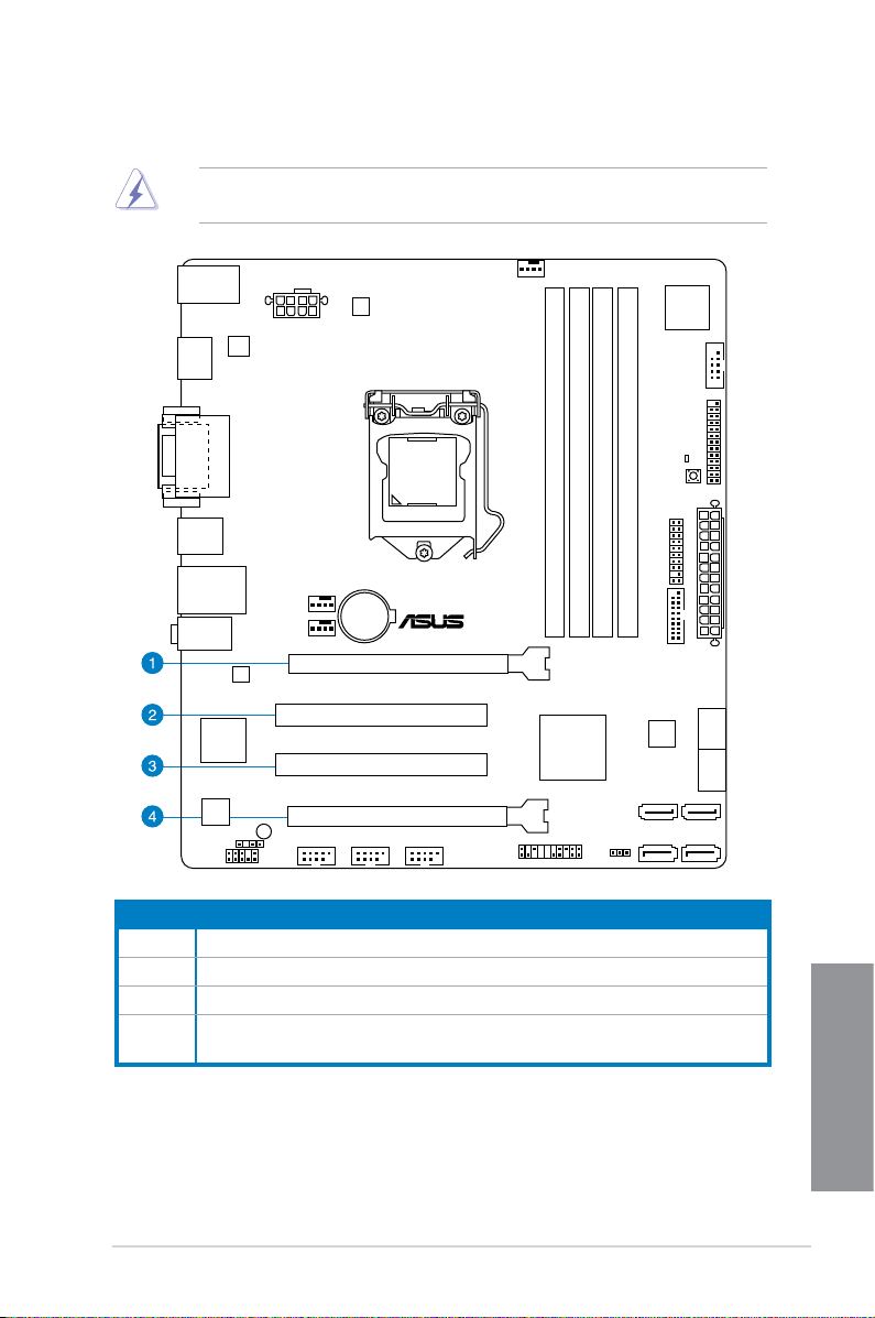
1.2.5 Expansion slots
Unplug the power cord before adding or removing expansion cards. Failure to do so may
cause you physical injury and damage motherboard components.
Slot No. Slot Description
1 PCIe 3.0/2.0 x16_1 slot (at x16 mode)
2 PCI_1 slot
3 PCI_2 slot
4 PCIe 2.0 x16_2 slot (run at x4 mode, compatible with PCIe x1 and x4 devices)
H87M-PLUS
PCIEX16_1
PCIEX16_2
PCI1
PCI2
EATX12V
1-12
Chapter 1: Product introduction
Chapter 1
• In single VGA card mode, use the PCIe 3.0/2.0 x16_1 slot (yellow) for a PCI Express
x16 graphics card to get better performance.
• We recommend that you provide sufcient power when running CrossFireX™ mode.
• Connect a chassis fan to the motherboard connector labeled CHA_FAN1/2 when
using multiple graphics cards for better thermal environment.
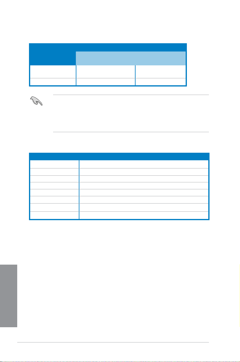
IRQ assignments for this motherboard
VGA conguration
PCIe Express operating mode
PCIe 3.0/2.0 x16_1 PCIe 2.0 x16_2
Single VGA/PCIe card x16 (single VGA recommended) N/A
Dual VGA/PCIe card x16 x4
A B C D E F G H
PCIe x16_1 shared – – – – – – –
PCIe x16_2 shared – – – – – – –
Intel SATA Controller – – – shared – – – –
Realtek LAN – – shared – – – – –
Intel xHCI – – – – – shared – –
Intel EHCI 1 – – – – – – – shared
Intel EHCI 2 – – – – shared – – –
HD Audio – – – – – – shared –
ASUS H87M-PLUS
1-13
Chapter 1
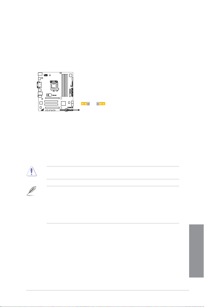
1.2.6 Jumpers
Clear RTC RAM (3-pin CLRTC)
This jumper allows you to clear the Real Time Clock (RTC) RAM in CMOS. You can clear the
CMOS memory of date, time, and system setup parameters by erasing the CMOS RTC RAM
data. The onboard button cell battery powers the RAM data in CMOS, which include system
setup information such as system passwords.
To erase the RTC RAM:
Except when clearing the RTC RAM, never remove the cap on CLRTC jumper default
position. Removing the cap will cause system boot failure!
1. Turn OFF the computer and unplug the power cord.
2. Move the jumper cap from pins 1-2 (default) to pins 2-3. Keep the cap on pins 2-3 for
about 5~10 seconds, then move the cap back to pins 1-2.
3. Plug the power cord and turn ON the computer.
4. Hold down the
<Del> key during the boot process and enter BIOS setup to reenter
data.
• If the steps above do not help, remove the onboard battery and move the jumper
again to clear the CMOS RTC RAM data. After clearing the CMOS, reinstall the
battery.
• You do not need to clear the RTC when the system hangs due to overclocking. For
system failure due to overclocking, use the CPU Parameter Recall (C.P.R) feature.
Shut down and reboot the system so the BIOS can automatically reset parameter
settings to default values.
H87M-PLUS
H87M-PLUS Clear RTC RAM
2 2 3
Normal
(Default)
Clear RTC
CLRTC
1-14
Chapter 1: Product introduction
Chapter 1
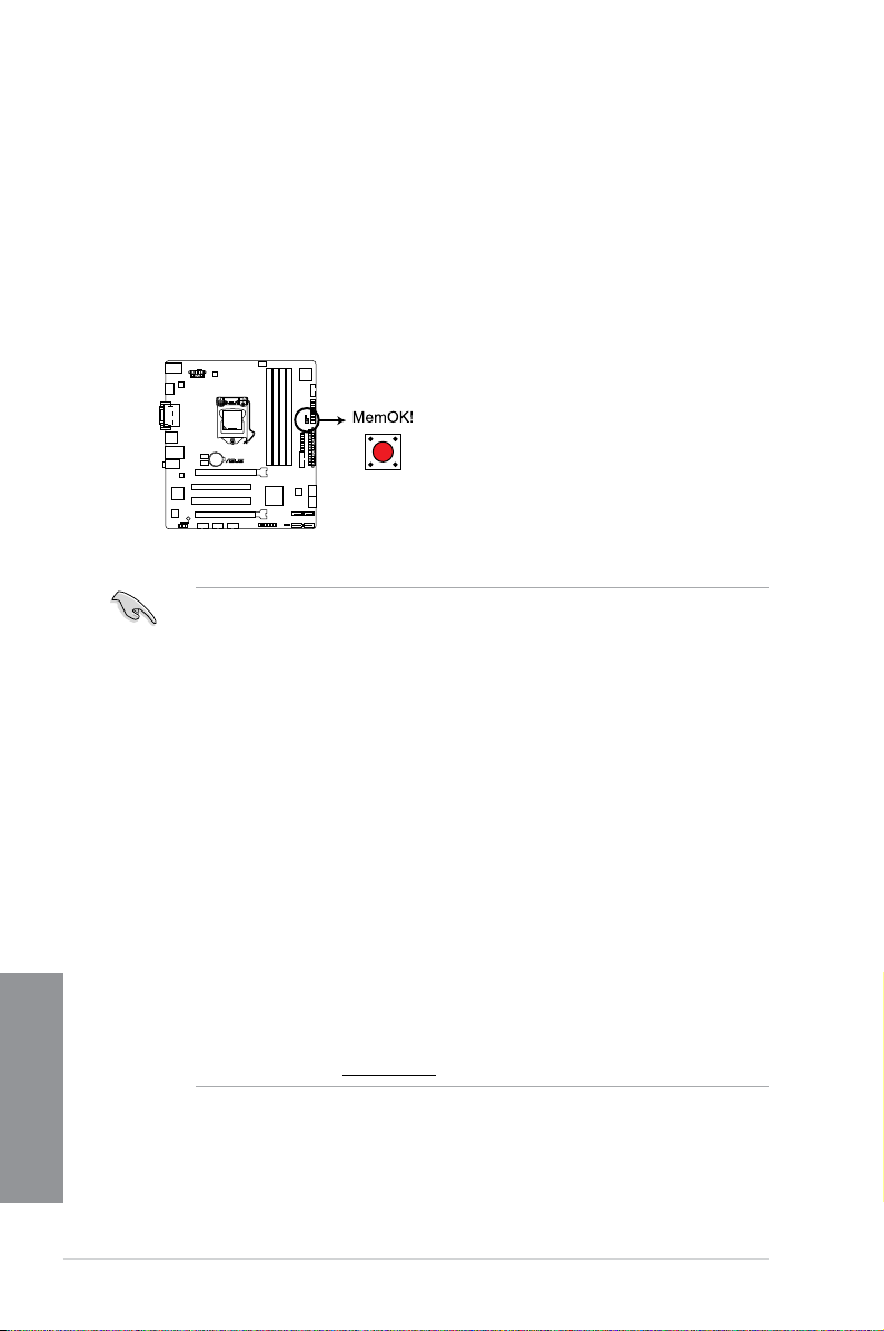
1.2.7 Onboard buttons and switches
Onboard switches and buttons allow you to ne-tune performance when working on a bare or
open-case system. This is ideal for overclockers and gamers who continually change settings
to enhance system performance.
1. MemOK! button
Installing DIMMs that are not compatible with the motherboard may cause system
boot failure, and the DRAM_LED near the MemOK! switch lights continuously. Press
and hold the MemOK! button until the DRAM_LED starts blinking to begin automatic
memory compatibility tuning for successful boot.
• Refer to section 1.2.8 Onboard LEDs for the exact location of the DRAM_LED.
• The DRAM_LED also lights up when the DIMM is not properly installed. Turn off the
system and reinstall the DIMM before using the MemOK! function.
• The MemOK! switch does not function under Windows
®
OS environment.
• During the tuning process, the system loads and tests failsafe memory settings. It
takes about 30 seconds for the system to test one set of failsafe settings. If the test
fails, the system reboots and test the next set of failsafe settings. The blinking speed
of the DRAM_LED increases, indicating different test processes.
• Due to memory tuning requirement, the system automatically reboots when each
timing set is tested. If the installed DIMMs still fail to boot after the whole tuning
process, the DRAM_LED lights continuously. Replace the DIMMs with ones
recommended in the Memory QVL (Qualied Vendors Lists) in this user manual or on
the ASUS website at www.asus.com.
• If you turn off the computer and replace DIMMs during the tuning process, the system
continues memory tuning after turning on the computer. To stop memory tuning, turn
off the computer and unplug the power cord for about 5–10 seconds.
• If your system fails to boot up due to BIOS overclocking, press the MemOK! switch
to boot and load the BIOS default settings. A message will appear during POST
reminding you that the BIOS has been restored to its default settings.
• We recommend that you download and update to the latest BIOS version from the
ASUS website at www.asus.com after using the MemOK! function.
H87M-PLUS
H87M-PLUS MemOK! switch
ASUS H87M-PLUS
1-15
Chapter 1
1.2.8 Onboard LEDs
2. DRAM LED
DRAM LED checks the DRAM in sequence during motherboard booting process. If an
error is found , the LED next to the error device will continue lighting until the problem
is solved. This user-friendly design provides an intuitional way to locate the root
problem within a second.
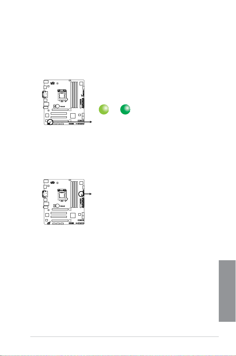
1. Standby Power LED
The motherboard comes with a standby power LED that lights up to indicate that the
system is ON, in sleep mode, or in soft-off mode. This is a reminder that you should
shut down the system and unplug the power cable before removing or plugging in any
motherboard component. The illustration below shows the location of the onboard LED.
SB_PWR
ON
Standby Power
Powered Off
OFF
H87M-PLUS
H87M-PLUS Onboard LED
H87M-PLUS
H87M-PLUS DRAM LED
DRAM LED
1-16
Chapter 1: Product introduction
Chapter 1
1.2.9 Internal connectors
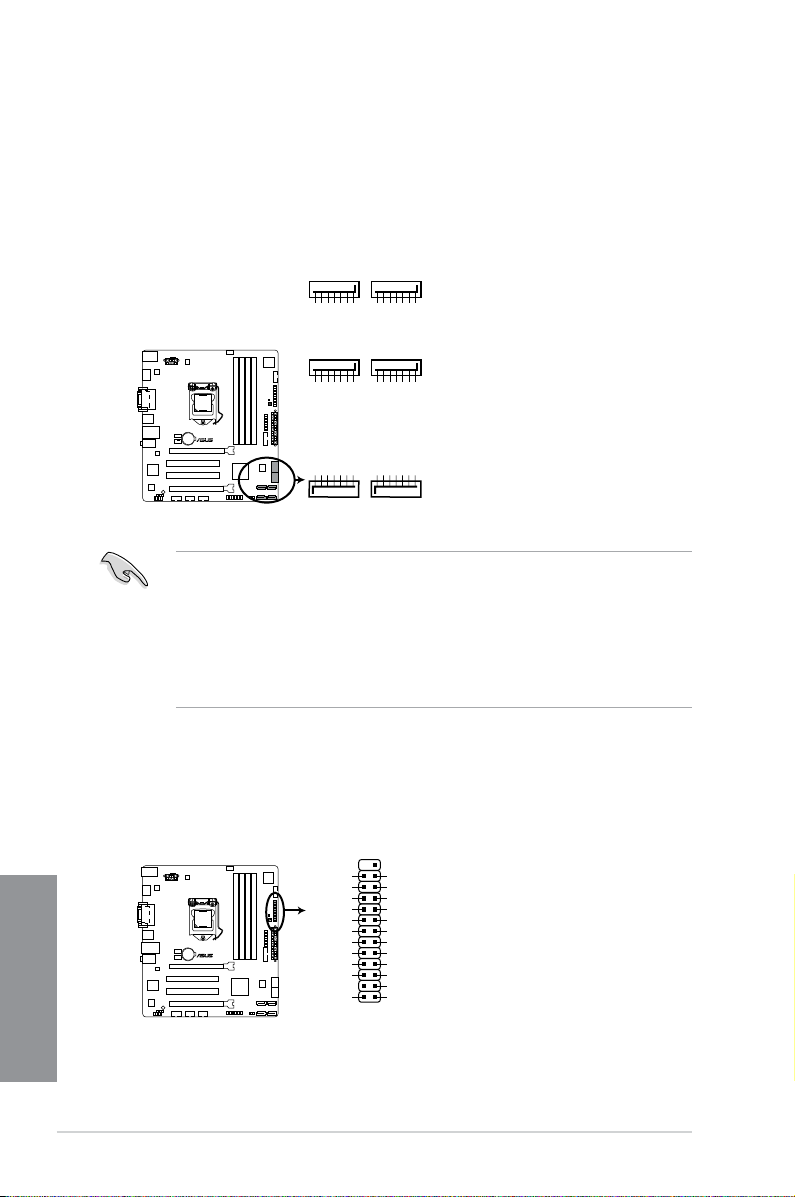
1. Intel
®
H87 Serial ATA 6.0 Gb/s connectors (7-pin SATA6G_1-6)
These connectors connect to Serial ATA 6.0 Gb/s hard disk drives via Serial ATA 6.0
Gb/s signal cables.
If you installed Serial ATA hard disk drives, you can create a RAID 0, 1, 5, and 10
conguration with the Intel
®
Rapid Storage Technology through the onboard Intel
®
H87
chipset.
• These connectors are set to [AHCI Mode] by default. If you intend to create a Serial
ATA RAID set using these connectors, set the SATA Mode item in the BIOS to [RAID
Mode]. Refer to section 3.6.3 SATA Conguration for details.
• Before creating a RAID set, refer to section
5.1 RAID congurations or the manual
bundled in the motherboard support DVD.
• When using hot-plug and NCQ, set the type of the SATA connectors in the BIOS to
[AHCI]. See section 3.6.3 SATA Conguration for details.
SATA6G_5
GND
RSATA_RXP5
RSATA_RXN5
GND
RSATA_TXN5
RSATA_TXP5
GND
SATA6G_6
GND
RSATA_RXP6
RSATA_RXN6
GND
RSATA_TXN6
RSATA_TXP6
GND
H87M-PLUS
H87M-PLUS SATA 6.0Gb/s connectors
GND
RSATA_TXP3
RSATA_TXN3
GND
RSATA_RXN3
RSATA_RXP3
GND
SATA6G_4SATA6G_3
GND
RSATA_TXP4
RSATA_TXN4
GND
RSATA_RXN4
RSATA_RXP4
GND
GND
RSATA_TXP1
RSATA_TXN1
GND
RSATA_RXN1
RSATA_RXP1
GND
SATA6G_2SATA6G_1
GND
RSATA_TXP2
RSATA_TXN2
GND
RSATA_RXN2
RSATA_RXP2
GND
2. LPT connector (26-1 pin LPT)
The LPT (Line Printing Terminal) connector supports devices such as a printer. LPT
standardizes as IEEE 1284, which is the parallel port interface on IBM PC-compatible
computers.
H87M-PLUS
H87M-PLUS Parallel Port Connector
LPT
PIN 1
SLCT
PE
BUSY
ACK#
PD7
PD6
PD5
PD4
PD3
PD2
PD1
PD0
STB#
GND
GND
GND
GND
GND
GND
GND
GND
SLIN#
INIT#
ERR#
AFD
 Loading...