


H61-PLUS
Motherboard

E8063
First Edition
January 2013
Copyright © 2013 ASUSTeK COMPUTER INC. All Rights Reserved.
No part of this manual, including the products and software described in it, may be reproduced, transmitted, transcribed, stored in a retrieval system, or translated into any language in any form or by any means, except documentation kept by the purchaser for backup purposes, without the express written permission of ASUSTeK COMPUTER INC. (“ASUS”).
Product warranty or service will not be extended if: (1) the product is repaired, modified or altered, unless such repair, modification of alteration is authorized in writing byASUS; or (2) the serial number of the product is defaced or missing.
ASUS PROVIDES THIS MANUAL “AS IS” WITHOUT WARRANTY OF ANY KIND, EITHER EXPRESS OR IMPLIED, INCLUDING BUT NOT LIMITED TO THE IMPLIED WARRANTIES OR CONDITIONS OF MERCHANTABILITY OR FITNESS FOR A PARTICULAR PURPOSE. IN NO EVENT SHALL ASUS, ITS DIRECTORS, OFFICERS, EMPLOYEES OR AGENTS BE LIABLE FOR ANY INDIRECT, SPECIAL, INCIDENTAL, OR CONSEQUENTIAL DAMAGES (INCLUDING DAMAGES FOR LOSS OF PROFITS, LOSS OF BUSINESS, LOSS OF USE OR DATA, INTERRUPTION OF BUSINESS AND THE LIKE), EVEN IF ASUS HAS BEEN ADVISED OF THE POSSIBILITY OF SUCH DAMAGES ARISING FROM ANY DEFECT OR ERROR IN THIS MANUAL OR PRODUCT.
SPECIFICATIONS AND INFORMATION CONTAINED IN THIS MANUAL ARE FURNISHED FOR INFORMATIONAL USE ONLY, AND ARE SUBJECT TO CHANGE AT ANY TIME WITHOUT NOTICE, AND SHOULD NOT BE CONSTRUED AS A COMMITMENT BY ASUS. ASUS ASSUMES NO RESPONSIBILITY OR LIABILITY FOR ANY ERRORS OR INACCURACIES THAT MAY APPEAR IN THIS MANUAL, INCLUDING THE PRODUCTS AND SOFTWARE DESCRIBED IN IT.
Products and corporate names appearing in this manual may or may not be registered trademarks or copyrights of their respective companies, and are used only for identification or explanation and to the owners’ benefit, without intent to infringe.
Offer to Provide Source Code of Certain Software
This product contains copyrighted software that is licensed under the General Public License (“GPL”), under the Lesser General Public License Version (“LGPL”) and/or other Free Open Source Software Licenses. Such software in this product is distributed without any warranty to the extent permitted by the applicable law. Copies of these licenses are included in this product.
Where the applicable license entitles you to the source code of such software and/or other additional data, you may obtain it for a period of three years after our last shipment of the product, either
(1)for free by downloading it from http://support.asus.com/download
or
(2)for the cost of reproduction and shipment, which is dependent on the preferred carrier and the location where you want to have it shipped to, by sending a request to:
ASUSTeK Computer Inc.
Legal Compliance Dept.
15 Li Te Rd.,
Beitou, Taipei 112
Taiwan
In your request please provide the name, model number and version, as stated in the About Box of the product for which you wish to obtain the corresponding source code and your contact details so that we can coordinate the terms and cost of shipment with you.
The source code will be distributed WITHOUT ANY WARRANTY and licensed under the same license as the corresponding binary/object code.
This offer is valid to anyone in receipt of this information.
ASUSTeK is eager to duly provide complete source code as required under various Free Open Source Software licenses. If however you encounter any problems in obtaining the full corresponding source code we would be much obliged if you give us a notification to the email address gpl@asus.com, stating the product and describing the problem (please DO NOT send large attachments such as source code archives, etc. to this email address).
ii

Contents
Safety information...................................................................................................... |
vi |
About this guide......................................................................................................... |
vii |
H61-PLUS specifications summary........................................................................... |
ix |
Package contents...................................................................................................... |
xii |
Chapter 1: |
Product introduction |
|
|
1.1 |
Special features............................................................................................. |
1-1 |
|
|
1.1.1 |
Product highlights ............................................................................ |
1-1 |
|
1.1.2 |
ASUS DIGI+ VRM . .......................................................................... |
1-2 |
|
1.1.3 |
ASUS Exclusive Features ............................................................... |
1-3 |
1.2 |
Before you proceed...................................................................................... |
1-5 |
|
1.3 |
Motherboard overview.................................................................................. |
1-6 |
|
|
1.3.1 |
Placement direction ......................................................................... |
1-6 |
|
1.3.2 |
Screw holes ..................................................................................... |
1-6 |
|
1.3.3 |
Motherboard layout .......................................................................... |
1-7 |
|
1.3.4 |
Layout contents . .............................................................................. |
1-8 |
1.4 |
Central Processing Unit (CPU).................................................................... |
1-8 |
|
|
1.4.1 |
CPU installation ............................................................................... |
1-9 |
|
1.4.2 |
CPU heatsink and fan assembly installation ................................. |
1-11 |
1.5 |
System memory.......................................................................................... |
1-13 |
|
|
1.5.1 |
Overview ........................................................................................ |
1-13 |
|
1.5.2 |
Memory configurations . ................................................................. |
1-14 |
|
1.5.3 |
Installing a DIMM ........................................................................... |
1-20 |
1.6 |
Expansion slots........................................................................................... |
1-21 |
|
|
1.6.1 |
Installing an expansion card .......................................................... |
1-21 |
|
1.6.2 |
Configuring an expansion card ...................................................... |
1-21 |
|
1.6.3 |
PCI slot .......................................................................................... |
1-21 |
|
1.6.4 |
PCI Express 2.0 x1 slot . ................................................................ |
1-21 |
|
1.6.5 |
PCI Express 3.0/2.0 x16 slot . ........................................................ |
1-22 |
1.7 |
Jumpers |
....................................................................................................... |
1-23 |
1.8 |
Connectors.................................................................................................. |
1-25 |
|
|
1.8.1 ............................................................................ |
Rear panel ports |
1-25 |
|
1.8.2 ........................................................................ |
Internal connectors |
1-26 |
1.9 |
Software .........................................................................................support |
1-31 |
|
|
1.9.1 ....................................................... |
Installing an operating system |
1-31 |
|
1.9.2 ............................................................... |
Support DVD information |
1-31 |
Chapter 2: |
BIOS information |
|
|
2.1 |
Managing and updating your BIOS............................................................. |
2-1 |
|
|
2.1.1 |
ASUS Update utility......................................................................... |
2-1 |
iii

|
2.1.2 |
ASUS EZ Flash 2............................................................................ |
2-2 |
|
2.1.3 |
ASUS CrashFree BIOS 3 utility....................................................... |
2-3 |
|
2.1.4 |
ASUS BIOS Updater....................................................................... |
2-4 |
2.2 |
BIOS setup program..................................................................................... |
2-6 |
|
2.3 |
Main menu................................................................................................... |
2-10 |
|
|
2.3.1 |
System Language [English]........................................................... |
2-10 |
|
2.3.2 |
System Date [Day xx/xx/xxxx]....................................................... |
2-10 |
|
2.3.3 |
System Time [xx:xx:xx].................................................................. |
2-10 |
|
2.3.4 |
Security.......................................................................................... |
2-10 |
2.4 |
Ai Tweaker menu......................................................................................... |
2-12 |
|
|
2.4.1 |
Memory Frequency [Auto]............................................................. |
2-13 |
|
2.4.2 |
EPU Power Saving Mode [Disabled]............................................. |
2-13 |
|
2.4.3 |
DRAM Timing Control.................................................................... |
2-13 |
|
2.4.4 |
CPU Power Management.............................................................. |
2-13 |
|
2.4.5 |
DIGI+ VRM.................................................................................... |
2-14 |
|
2.4.6 |
CPU Voltage [Offset Mode]............................................................ |
2-15 |
|
2.4.7 |
DRAM Voltage [Auto]..................................................................... |
2-16 |
|
2.4.8 |
VCCSA Voltage [Auto]................................................................... |
2-16 |
|
2.4.9 |
PCH Voltage [Auto]........................................................................ |
2-16 |
|
2.4.10 |
CPU PLL Voltage [Auto]................................................................ |
2-16 |
2.5 |
Advanced menu.......................................................................................... |
2-17 |
|
|
2.5.1 |
CPU Configuration......................................................................... |
2-17 |
|
2.5.2 |
PCH Configuration......................................................................... |
2-19 |
|
2.5.3 |
SATAConfiguration........................................................................ |
2-20 |
|
2.5.4 |
SystemAgent Configuration.......................................................... |
2-20 |
|
2.5.5 |
USB Configuration......................................................................... |
2-21 |
|
2.5.6 |
Onboard Devices Configuration.................................................... |
2-21 |
|
2.5.7 |
APM............................................................................................... |
2-23 |
|
2.5.8 |
Network Stack............................................................................... |
2-24 |
2.6 |
Monitor menu.............................................................................................. |
2-25 |
|
|
2.6.1 |
CPU Temperature / MB Temperature [xxxºC/xxxºF]...................... |
2-25 |
|
2.6.2 |
CPU / Chassis Fan Speed [xxxx RPM] or [Ignore] / [N/A]............. |
2-25 |
|
2.6.3 |
CPU Q-Fan Control [Enabled]....................................................... |
2-26 |
|
2.6.4 |
Chassis Q-Fan Control [Enabled].................................................. |
2-26 |
|
2.6.5 |
CPU Voltage, 3.3V Voltage, 5V Voltage, 12V Voltage................... |
2-27 |
|
2.6.6 |
Anti Surge Support [Enabled]........................................................ |
2-27 |
2.7 |
Boot menu................................................................................................... |
2-28 |
|
|
2.7.1 |
Fast Boot [Enabled]....................................................................... |
2-29 |
|
2.7.2 |
Full Screen Logo [Enabled]........................................................... |
2-29 |
iv

|
2.7.3 |
Bootup NumLock State [On].......................................................... |
2-30 |
|
2.7.4 |
Wait for ‘F1’ If Error [Enabled]....................................................... |
2-30 |
|
2.7.5 |
Option ROM Messages [Force BIOS]........................................... |
2-30 |
|
2.7.6 |
Interrupt 19 Capture [Disabled]..................................................... |
2-30 |
|
2.7.7 |
Setup Mode [EZ Mode].................................................................. |
2-30 |
|
2.7.8 |
CSM (Compatibility Support Module)............................................ |
2-30 |
|
2.7.9 |
Security Boot................................................................................. |
2-31 |
|
2.7.10 |
Boot Option Priorities..................................................................... |
2-33 |
|
2.7.11 |
Boot Override................................................................................ |
2-34 |
2.8 |
Tools menu.................................................................................................. |
2-35 |
|
|
2.8.1 |
ASUS EZ Flash 2 Utility................................................................. |
2-35 |
|
2.8.2 |
ASUS SPD Information................................................................. |
2-35 |
|
2.8.3 |
ASUS O.C. Profile......................................................................... |
2-35 |
2.9 |
Exit menu..................................................................................................... |
2-36 |
|
Appendices
Notices...................................................................................................................... |
A-1 |
ASUS contact information...................................................................................... |
A-3 |

Safety information
Electrical safety
•To prevent electrical shock hazard, disconnect the power cable from the electrical outlet before relocating the system.
•When adding or removing devices to or from the system, ensure that the power cables for the devices are unplugged before the signal cables are connected. If possible, disconnect all power cables from the existing system before you add a device.
•Before connecting or removing signal cables from the motherboard, ensure that all power cables are unplugged.
•Seek professional assistance before using an adapter or extension cord. These devices could interrupt the grounding circuit.
•Ensure that your power supply is set to the correct voltage in your area. If you are not sure about the voltage of the electrical outlet you are using, contact your local power company.
•If the power supply is broken, do not try to fix it by yourself. Contact a qualified service technician or your retailer.
Operation safety
•Before installing the motherboard and adding devices on it, carefully read all the manuals that came with the package.
•Before using the product, ensure all cables are correctly connected and the power cables are not damaged. If you detect any damage, contact your dealer immediately.
•To avoid short circuits, keep paper clips, screws, and staples away from connectors, slots, sockets and circuitry.
•Avoid dust, humidity, and temperature extremes. Do not place the product in any area where it may become wet.
•Place the product on a stable surface.
•If you encounter technical problems with the product, contact a qualified service technician or your retailer.
vi

About this guide
This user guide contains the information you need when installing and configuring the motherboard.
How this guide is organized
This guide contains the following parts:
•Chapter 1: Product introduction
This chapter describes the features of the motherboard and the new technology it supports.
•Chapter 2: BIOS information
This chapter tells how to change system settings through the BIOS Setup menus. Detailed descriptions of the BIOS parameters are also provided.
Where to find more information
Refer to the following sources for additional information and for product and software updates.
1.ASUS websites
The ASUS website provides updated information on ASUS hardware and software products. Refer to the ASUS contact information.
2.Optional documentation
Your product package may include optional documentation, such as warranty flyers, that may have been added by your dealer. These documents are not part of the standard package.
vii

Conventions used in this guide
To ensure that you perform certain tasks properly, take note of the following symbols used throughout this manual.
DANGER/WARNING: Information to prevent injury to yourself when trying to complete a task.
CAUTION: Information to prevent damage to the components when trying to complete a task
IMPORTANT: Instructions that you MUST follow to complete a task..
NOTE: Tips and additional information to help you complete a task.
Typography
Bold text |
Indicates a menu or an item to select. |
Italics |
Used to emphasize a word or a phrase. |
<Key> |
Keys enclosed in the less-than and greater-than sign |
|
means that you must press the enclosed key. |
|
Example: <Enter> means that you must press the Enter or |
|
Return key. |
<Key1> + <Key2> + <Key3> |
If you must press two or more keys simultaneously, the key |
|
names are linked with a plus sign (+). |
viii

H61-PLUS specifications summary
CPU |
LGA1155 socket for Intel® 3rd/2nd Generation Core™ i7, i5, i3, Pentium®, |
|
and Celeron® processors |
|
Supports Intel® 22nm/32nm CPU |
|
Supports Intel® Turbo Boost Technology 2.0 |
|
• The Intel® Turbo Boost Technology 2.0 support depends on the CPU |
|
types. |
|
• Refer to www.asus.com for Intel® CPU support list. |
Chipset
Memory
Expansion slots
Storage
Intel® H61 Express Chipset
2 x DIMMs, max. 16GB, DDR3 2200 (O.C.) / 2133 (O.C.) / 2000 (O.C.) /
1866 (O.C.) / 1600 / 1333 / 1066 MHz, non-ECC, un-buffered memory
Dual-channel memory architecture
Supports Intel® Extreme Memory Profile (XMP)
•DDR3 1600 MHz and higher memory frequency is supported by Intel® 3rd generation processors.
•Refer to www.asus.com for the latest Memory QVL (Qualified Vendors
List).
•When you install a total memory of 4GB capacity or more, Windows® 32-bit operating system may only recognize less than 3GB. We recommend a maximum of 3GB system memory if you are using a Windows® 32-bit operating system.
1 x PCI Express 3.0*/2.0 x16 slot (blue, at x16 mode) 2 x PCI Express 2.0 x1 slots
3 x PCI slots
•PCIe 3.0 speed is supported by Intel® 3rd generation Core™ processors.
Intel® H61 Express Chipset:
-4 x Serial ATA 3 Gb/s connectors
-Supports Intel® Rapid Start Technology and Intel® Smart Connect Technology*
LAN |
• Supports on Intel® Core™ processor family with Windows® 7 operating system. |
|
Realtek® 8111F PCIe Gigabit LAN controller |
|
|
Audio |
Realtek® ALC887 8-channel High DefinitionAudio CODEC |
|
|
• Use a chassis with HD audio module in the front panel to support an |
|
USB |
8-channel audio output. |
|
Intel® H61 Express Chipset: |
|
|
|
- 10 x USB 2.0/1.1 ports (6 ports at the mid-board, 4 ports at the back |
|
|
panel) |
|
|
(continued on the next page) |
|
ix

H61-PLUS specifications summary
ASUS unique features
Other features Rear panel ports
Internal connectors/ jumpers
ASUS DIGI+ VRM
-Digital Power Control: Digital Power Design for the CPU
-ASUS 3+1 Phase Power Design
ASUS EPU
- EPU
ASUS Exclusive Features
-Network iControl* featuring instant network bandwidth domination for top network program in use
-Disk Unlocker featuring 3TB+ HDD support
-ASUS Anti-Surge Protection
-ASUS AI Charger
-ASUS AI Suite II
-ASUS Low EMI
ASUS Quiet Thermal Solution
-ASUS Fan Xpert
-ASUS Fanless Design: Stylish Heatsink solution
ASUS EZ DIY
-ASUS UEFI BIOS featuring friendly graphics user interface
-ASUS CrashFree BIOS 3
-ASUS EZ Flash 2
-ASUS MyLogo 2™
•The Network iControl feature does not support Windows® XP/Vista operating systems.
100% All High-quality Conductive Polymer Capacitors
1 x PS/2 keyboard port (purple)
1 x PS/2 mouse port (green)
1 x COM port
1 x LPT port
4 x USB 2.0/1.1 ports
1 x LAN (RJ-45) port
3 x Audio jacks
3 x USB 2.0/1.1 connectors support additional 6 USB 2.0/1.1 ports 4 x SATA 3 Gb/s connectors
1 x 4-pin CPU fan connector
1 x 4-pin chassis fan connector
1 x Front panel audio connector
1 x S/PDIF Out connector
1 x System panel connector
1 x Speaker connector
1 x 24-pin EATX power connector
1 x 4-pin ATX 12V power connector
(continued on the next page)
H61-PLUS specifications summary
BIOS features
Manageability
Support DVD
Form factor
64 Mb Flash ROM, UEFI BIOS, PnP, DMI v2.0, WfM 2.0, ACPI v2.0a, SM BIOS v2.7, SLP 3.0, Multi-language BIOS, ASUS EZ Flash 2, ASUS CrashFree BIOS 3, F12 PrintScreen function, F3 Shortcut function, and ASUS DRAM SPD (Serial Presence Detect) memory information
WfM 2.0, DMI v2.0, WOR by PME, PXE
Drivers
ASUS utilities
ASUS Update
Anti-virus software (OEM version)
ATX form factor: 12 in x 7.5 in (30.5 cm x 19.1 cm)
Specifications are subject to change without notice.
xi
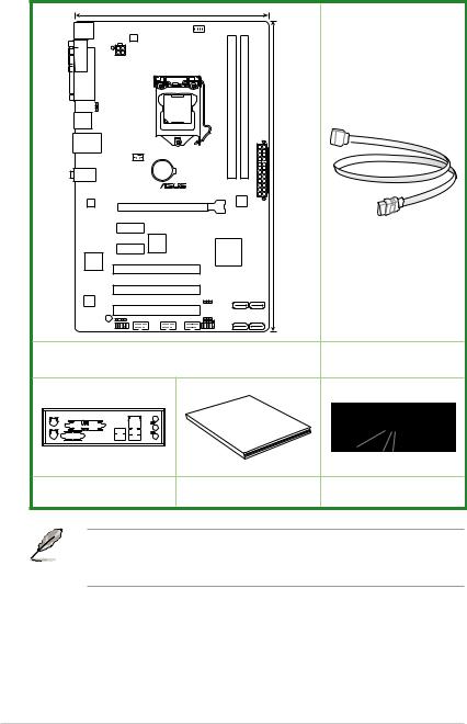
Package contents
Check your motherboard package for the following items.
|
|
19.1cm(7.5in) |
|
|
|
|
|
KBMS |
|
|
|
|
|
|
|
|
DIGI |
|
CPU_FAN |
|
|
|
|
|
+VRM |
|
|
|
|
|
|
COM |
ATX12V |
|
|
|
|
|
|
|
|
|
|
|
|
|
|
LPT |
|
|
|
module) |
module) |
|
|
KB_USBPWB |
LGA1155 |
|
(64bit, 240-pin |
(64bit, 240-pin |
|
|
|
USB34 |
|
|
|
A1 |
B1 |
|
|
|
|
|
|
DIMM |
DIMM |
|
|
LAN_USB12 |
|
|
|
DDR3 |
DDR3 |
|
|
|
CHA_FAN |
|
|
|
|
EATXPWR |
30.5cm(12.0in) |
AUDIO |
|
BATTERY |
|
|
|
||
|
|
|
|
|
|||
|
|
H61-PLUS |
|
|
|||
|
|
|
|
|
|
||
|
|
|
|
|
64Mb |
|
|
RTL |
|
|
|
|
BIOS |
|
|
8111F |
|
PCIEX16 |
|
|
|
|
|
|
|
|
|
|
|
|
|
|
PCIEX1_1 |
|
|
|
|
|
|
|
|
ASM |
|
|
|
|
|
|
PCIEX1_2 |
1083 |
|
Intel® |
|
|
|
|
|
|
|
|
|
||
Super |
|
|
|
H61 |
|
|
|
|
|
|
|
|
|
|
|
I/O |
|
|
|
|
|
|
|
|
|
PCI1 |
|
|
|
|
|
|
|
PCI2 |
|
|
|
|
|
ALC |
|
|
CLRTC |
|
|
|
|
|
|
|
|
|
|
|
|
887 |
|
|
|
|
|
|
|
|
|
PCI3 |
|
SATA3G_4 |
SATA3G_3 |
|
|
SB_PWR |
SPDIF_OUT |
|
|
USBPWF SATA3G_2 SATA3G_1 |
|
||
USB56 |
USB78 |
USB910 |
|
||||
|
SPEAKER |
|
|
|
|||
|
AAFP |
|
|
F_PANEL |
|
|
|
|
ASUS H61-PLUS motherboard |
|
2 x Serial ATA 3 Gb/s cables |
||||
|
|
|
|
Guide |
|
||
|
|
|
|
User |
|
|
|
1 x I/O Shield |
|
|
User Guide |
Support DVD |
|||
•If any of the above items is damaged or missing, contact your retailer.
•The illustrations above are for reference only.Actual product specifications may vary with different models.
xii
Product introduction |
1 |
1.1Special features
1.1.1Product highlights
LGA1155 socket for Intel® 3rd/2nd Generation Core™ i7, Core™ i5, Core™ i3, Pentium®, and Celeron® processors
This motherboard supports the Intel® 3rd/2nd generation Core™ i7, Core™ i5, Core™ i3, Pentium®, and Celeron® processors in the LGA1155 package, with memory and PCI Express controllers integrated to support onboard graphics out with dedicated chipsets, 2-channel
(2 DIMMs) DDR3 memory, and 16 PCI Express 3.0/2.0 lanes. This provides great graphics performance. Intel® 3rd/2nd generation Core™ i7, Core™ i5, Core™ i3, Pentium®, and Celeron® processors are among the most powerful and energy efficient CPUs in the world.
Intel® H61 Express Chipset
The Intel® H61 Express Chipset is the latest single-chipset design to support the new 1155 socket Intel® 3rd/2nd Generation Core™ i7, Core™ i5, Core™ i3, Pentium®, and Celeron® processors. It provides improved performance by utilizing serial point-to-point links, which allows increased bandwidth and stability.
Dual-Channel DDR3 2200 (O.C.) / 2133 (O.C.) / 2000 (O.C.) / 1866 (O.C.) / 1600 / 1333 / 1066 MHz support
The motherboard supports DDR3 memory that features data transfer rates of 2200 (O.C.)/
2133 (O.C.) / 2000 (O.C.) / 1866 (O.C.) / 1600 / 1333 / 1066 MHz to meet the higher bandwidth requirements of the latest 3D graphics, multimedia, and Internet applications. The dual-channel DDR3 architecture enlarges the bandwidth of your system memory to boost system performance.
*DDR3 1600 MHz and higher memory frequency is supported by Intel® 3rd generation processors.
**Due to the CPU behavior, DDR3 2133/1866 memory modules runs at DDR3 2000/1800 MHz frequencies.
PCI Express® 3.0
PCI Express® 3.0 (PCIe 3.0) is the latest PCI Express bus standard with improved encoding schemes that provide twice the performance of the current PCIe 2.0. The total bandwidth for a x16 link reaches a maximum of 32Gb/s, double the 16 Gb/s of PCIe 2.0 (in x16 mode). As such, PCIe 3.0 provides users an unprecendented data speeds, combined with the convenience and seamless transition offerred by complete backward compatibility with PCIe 1.0 and PCIe 2.0 devices. PCIe 3.0 will become a must-have feature for users who wish to
improve and optimize graphic performance, as well as have the latest technology available to them.
* PCI 3.0 speed is supported by Intel® 3rd generation Core™ processors.
ASUS H61-PLUS |
1-1 |
Intel® Smart Connect Technology
Your computer can receive fresh updates for selected applications, even when the system is in sleep mode. This means less time waiting for applications to update and sync with the cloud, leading to a more efficient computing experience.
Intel® Rapid Start Technology
Intel® Rapid Start Technology allows your system to receive updates for your web applications in real-time even when your system is in sleep mode, saving wait time and power usage.
8-channel high definition audio
The onboard 8-channel HD audio (High DefinitionAudio, previously codenamedAzalia) CODEC enables high-quality 192KHz/24-bit audio output and jack-detect feature that automatically detects and identifies what types of peripherals are plugged into the audio I/O jacks and notifies users of inappropriate connection, which means there will be no more confusion of Line-in, Line-out, and Mic jacks.
* Use a chassis with HD audio module in the front panel to support an 8-channel audio output.
Gigabit LAN solution
The onboard LAN controller is a highly integrated Gb LAN controller. It is enhanced with an
ACPI management function to provide efficient power management for advanced operating systems.
100% All High-quality Conductive Polymer Capacitors
This motherboard uses all high-quality conductive polymer capacitors for durability, improved lifespan, and enhanced thermal capacity.
1.1.2ASUS DIGI+ VRM
Digital Power Design for the CPU
ASUS motherboards using the Intel® H61 chipset employ precise digital voltage regulation for the CPU, called DIGI+ VRM (Voltage Regulation Modules) digital power design. The CPU voltage and VRM frequency are adjusted via either carefully developed automated modes, or by using user-defined profiles. The effect is that DIGI+ VRM technology ensures greater energy efficiency and the best possible PC stability. Engineered and tested to assure unmitigated performance,ASUS H61 boards with DIGI+ VRM remain efficient and stability, for reliable application in every scenario.
EPU
EPU (Energy Processing Unit), the world’s first real-time system power-saving chip, automatically detects the current system load and intelligently moderates power usage. It offers a system-wide energy optimization, reduces fan noise, and extends the component’s lifespan.
1-2 |
Chapter 1: Product introduction |
1.1.3ASUS Exclusive Features
ASUS UEFI BIOS (EZ Mode)
ASUS UEFI BIOS, a UEFI compliant architecture, offers the first mouse-controlled intuitive graphical BIOS interface that goes beyond the traditional keyboard-only BIOS controls, providing you with more flexibility, convenience, and easy to navigate EFI BIOS than the traditional BIOS versions. It offers you with dual selectable modes and native support for hard drives larger than 2.2 TB.
ASUS UEFI BIOS includes the following new features:
•F12 BIOS snapshot hotkey
•F3 Shortcut for most accessed information
•ASUS DRAM SPD (Serial Presence Detect) information detecting faulty DIMMs, and helping with difficult POST situations.
Network iControl
Network iControl is an intuitive one-step network control center that makes it easier for you to manage your bandwidth and allows you to set, monitor, and schedule the bandwidth priorities for your network programs. It allows you to automatically connect to a PPPoE network for a more convenient online experience.
* The ASUS Network iControl feature does not support Windows® XP/Vista operating systems.
Ai Charger
Ai Charger is ASUS fast-charging software that supports iPod, iPhone, and iPad.
*Check your USB mobile device if it fully supports the BC 1.1 function.
**The actual charging speed may vary with your USB device’s conditions.
***Ai Charger is only supported when you set the USB device wake-up jumpers to +5VSB. See section 1.7 Jumpers for details.
AI Suite II
With its user-friendly interface, ASUS AI Suite II integrates several ASUS utilities and allows you to launch and operate these utilities simultaneously. It allows you to supervise fan speed control, and voltage and sensor readings. This all-in-one software offers diverse and ease to use functions, with no need to switch back and forth between different utilities.
ASUS Anti-Surge Protection
This special design protects expensive devices and the motherboard from damage caused by power surges from switching power supply unit (PSU).
ASUS Fan Xpert
ASUS Fan Xpert intelligently allows you to adjust the CPU fan and chassis fan speeds according to different ambient temperatures caused by different climate conditions in different geographic regions and your PC’s loading. The built-in variety of useful profiles offer flexible controls of fan speed to achieve a quiet and cool environment.
ASUS H61-PLUS |
1-3 |
Low EMI
A special low-radiation design shields you from harmful electromagnetic exposure by eliminating 50% of radiation.
1.Radiation Deduction Design minimizes harmful electromagnetic radiation output with exclusive circuit design to cancel electrical charge.
2.The Radiation Moat Design effectively blocks radiation to prevent discharge spread.
ESD
Protect Your Computer with ESD Guards. Electrostatic discharge (ESD) conditions can happen while plugging or unplugging any USB peripherals-causing damage to the computer. ASUS ESD Guards clamp the ESD voltage and shunt the majority of the ESD current away for a more reliable computing environment.
ASUS MyLogo2™
Turn your favorite photos into 256-color boot logos to personalize your system.
ASUS CrashFree BIOS 3
ASUS CrashFree BIOS 3 is an auto-recovery tool that allows you to restore a corrupted BIOS file using the bundled support DVD or a USB flash disk that contains the BIOS file.
ASUS EZ Flash 2
ASUS EZ Flash 2 is a user-friendly utility that allows you to update the BIOS without using a bootable floppy disk or an OS-based utility.
C.P.R. (CPU Parameter Recall)
The BIOS C.P.R. feature automatically restores the CPU default settings when the system hangs due to overclocking failure. C.P.R. eliminates the need to open the system chassis and clear the RTC data. Simply shut down and reboot the system, and the BIOS automatically restores the CPU parameters to their default settings.
ErP ready
The motherboard is European Union´s Energy-related Products (ErP) ready, and ErP requires products to meet certain energy efficiency requirements in regards to energy consumptions. This is in line with ASUS vision of creating environment-friendly and energyefficient products through product design and innovation to reduce carbon footprint of the product and thus mitigate environmental impacts.
1-4 |
Chapter 1: Product introduction |
1.2Before you proceed
Take note of the following precautions before you install motherboard components or change any motherboard settings.
• Unplug the power cord from the wall socket before touching any component.
• Before handling components, use a grounded wrist strap or touch a safely grounded object or a metal object, such as the power supply case, to avoid damaging them due to static electricity.
•Hold components by the edges to avoid touching the ICs on them.
•Whenever you uninstall any component, place it on a grounded antistatic pad or in the bag that came with the component.
•Before you install or remove any component, switch off the ATX power supply and detach its power cord. Failure to do so may cause severe damage to the motherboard, peripherals, or components.
Standby Power LED
The motherboard comes with a standby power LED that lights up to indicate that the system is ON, in sleep mode, or in soft-off mode. This is a reminder that you should shut down
the system and unplug the power cable before removing or plugging in any motherboard component. The illustration below shows the location of the onboard LED.
H61-PLUS
SB_PWR
ON OFF
Standby Power Powered Off
H61-PLUS Onboard LED
ASUS H61-PLUS |
1-5 |
1.3Motherboard overview
1.3.1Placement direction
When installing the motherboard, ensure that you place it into the chassis in the correct orientation. The edge with external ports goes to the rear part of the chassis as indicated in the image below.
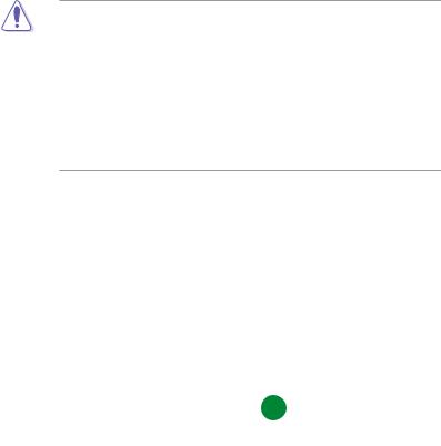
1.3.2Screw holes
Place six screws into the holes indicated by circles to secure the motherboard to the chassis.
DO NOT overtighten the screws! Doing so can damage the motherboard.
Place this side towards the rear of the chassis
H61-PLUS
|
|
|
|
|
|
|
|
|
|
|
|
|
|
|
|
|
|
|
|
|
|
|
|
|
|
|
|
|
|
|
|
|
|
|
|
|
|
|
|
|
|
|
|
|
|
|
|
|
|
|
|
|
|
|
|
|
|
|
|
|
|
|
|
|
|
|
|
|
|
|
|
|
|
|
|
|
|
|
|
|
|
|
|
|
|
|
|
|
|
|
|
|
|
|
|
|
|
|
|
|
|
|
|
|
|
|
|
|
|
|
|
|
|
|
|
|
|
|
|
|
|
|
|
|
|
|
|
|
|
|
|
|
|
|
|
|
|
|
|
|
|
|
|
|
|
|
|
|
|
|
|
|
|
|
|
|
|
|
|
|
|
|
|
|
|
|
|
|
|
|
|
|
|
|
|
|
|
|
|
|
|
|
|
|
|
|
|
|
|
|
|
|
|
|
|
|
|
|
|
|
|
|
|
|
|
|
|
|
|
|
|
|
|
|
|
|
|
|
|
|
|
|
|
|
|
|
|
|
|
|
|
|
|
|
|
|
|
|
|
|
|
|
|
|
|
|
|
|
|
|
|
|
|
|
|
|
|
|
|
|
|
|
|
|
|
|
|
|
|
|
|
|
|
|
|
|
|
|
|
|
|
|
|
|
|
|
|
|
|
|
|
|
|
|
|
|
|
|
|
|
|
|
|
|
|
|
|
|
|
|
|
|
|
|
|
|
|
|
|
|
|
|
|
|
|
|
|
|
|
|
|
|
|
|
|
|
|
|
|
|
|
|
|
|
|
|
|
|
|
|
|
|
|
|
|
|
|
|
|
|
|
|
|
|
|
|
|
|
|
|
|
|
|
|
|
|
|
|
|
|
|
|
|
|
|
|
|
|
|
|
|
|
|
|
|
|
|
|
|
|
|
|
|
|
|
|
|
|
|
|
|
|
|
|
|
|
|
|
|
|
|
|
|
|
|
|
|
|
|
|
|
|
|
|
|
|
|
|
|
|
|
|
|
|
|
|
|
|
|
|
|
|
|
|
|
|
|
|
|
|
|
|
|
|
|
|
|
|
|
|
|
|
|
|
|
|
|
|
|
|
|
|
|
|
|
|
|
|
|
|
|
|
|
|
|
|
|
|
|
|
|
|
|
|
|
|
|
|
|
|
|
|
|
|
|
|
|
|
|
|
|
|
|
|
|
|
|
|
|
|
|
|
|
|
|
|
|
|
|
|
|
|
|
|
|
|
|
|
|
|
|
|
|
|
|
|
|
|
|
|
|
|
|
|
|
|
|
|
|
|
|
|
|
|
|
|
|
|
|
|
|
|
|
|
|
|
|
|
|
|
|
|
|
|
|
|
|
|
|
|
|
|
|
|
|
|
|
|
|
|
|
|
|
|
|
|
|
|
|
|
|
|
|
|
|
|
|
|
|
|
|
|
|
|
|
|
|
|
|
|
|
|
|
|
|
|
|
|
|
|
|
|
|
|
|
|
|
|
|
|
|
|
|
|
|
|
|
|
|
|
|
|
|
|
|
|
|
|
|
|
|
|
|
|
|
|
|
|
|
|
|
|
|
|
|
|
|
|
|
|
|
|
1-6 |
|
|
|
|
|
|
|
|
|
|
|
|
|
|
Chapter 1: Product introduction |
|||||||||||||||||||||
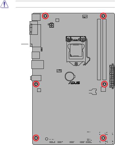
1.3.3Motherboard layout
1 |
2 |
3 |
|
4 |
3 |
|
5 |
|
|
|
|
|
19.1cm(7.5in) |
|
|
|
|
|
|
KBMS |
|
|
|
|
|
|
|
|
|
|
|
DIGI |
|
|
CPU_FAN |
|
|
|
|
|
|
+VRM |
|
|
|
|
|
|
|
COM |
ATX12V |
|
|
|
|
|
|
|
|
|
|
|
|
|
|
|
|
|
|
LPT |
|
|
|
|
|
module) |
module) |
|
|
KB_USBPWB |
|
|
LGA1155 |
|
|
(64bit, 240-pin |
(64bit, 240-pin |
|
|
USB34 |
|
|
|
|
|
A1 |
B1 |
|
|
|
|
|
|
|
|
DIMM |
DIMM |
|
|
LAN_USB12 |
|
|
|
|
|
DDR3 |
DDR3 |
|
|
|
|
|
|
|
|
|
|
EATXPWR |
2 |
|
|
CHA_FAN |
|
|
|
|
|
30.5cm(12.0in) |
|
AUDIO |
|
|
BATTERY |
|
|
|
|
|
|
|
|
|
|
|
|
|
|
|
|
|
|
|
H61-PLUS |
|
|
|
|
||
|
|
|
|
|
|
|
64Mb |
|
|
RTL |
|
|
|
|
|
|
BIOS |
|
|
8111F |
|
|
PCIEX16 |
|
|
|
|
|
|
|
|
|
|
|
|
|
|
|
|
|
|
PCIEX1_1 |
|
|
|
|
|
|
|
|
|
|
ASM |
|
|
|
|
|
|
|
|
PCIEX1_2 |
1083 |
|
|
Intel® |
|
|
|
|
|
|
|
|
|
|
|
||
Super |
|
|
|
|
|
H61 |
|
|
|
|
|
|
|
|
|
|
|
|
|
I/O |
|
|
|
|
|
|
|
|
|
|
|
|
PCI1 |
|
|
|
|
|
6 |
|
|
|
|
|
|
|
|
|
|
|
|
|
PCI2 |
|
|
|
|
|
7 |
ALC |
|
|
|
|
CLRTC |
|
|
|
|
|
|
|
|
|
|
|
|
|
|
887 |
|
|
|
|
|
|
|
|
|
|
|
|
PCI3 |
|
|
SATA3G_4 SATA3G_3 |
8 |
||
|
|
|
|
|
|
||||
|
SPDIF_OUT |
|
|
USBPWF |
|
|
|
||
SB_PWR |
|
USB56 |
USB78 |
USB910 |
SPEAKER SATA3G_2 |
SATA3G_1 |
|||
|
|
|
|||||||
AAFP |
|
|
|
|
|
F_PANEL |
|
|
|
|
|
|
|
|
|
|
|
|
|
14 |
13 |
12 |
11 |
|
10 |
9 |
|
|
|
ASUS H61-PLUS |
1-7 |
1.3.4Layout contents
Connectors/Jumpers/Slots/LED |
Page |
|
1. |
Keyboard and USB device wake-up (3-pin KB_USBPWB) |
1-24 |
2. |
ATX power connectors (24-pin EATXPWR, 4-pin ATX12V) |
1-27 |
3. |
CPU and chassis fan connectors (4-pin CPU_FAN, 4-pin CHA_FAN) |
1-29 |
4. |
Intel® LGA1155 CPU socket |
1-8 |
5. |
DDR3 DIMM slots |
1-13 |
6. |
Clear RTC RAM (3-pin CLRTC) |
1-23 |
7. |
USB device wake-up (3-pin USBPWF) |
1-24 |
8. |
Intel® H61 Serial ATA 3.0Gb/s connectors (7-pin SATA3G_1/2/3/4) |
1-28 |
9. |
Speaker connector (4-pin SPEAKER) |
1-30 |
10. |
System panel connector (10-1 pin F_PANEL) |
1-30 |
11. |
USB 2.0 connectors (10-1 pin USB56, USB78, USB910) |
1-29 |
12. |
Digital audio connector (4-1 pin SPDIF_OUT) |
1-28 |
13. |
Front panel audio connector (10-1 pin AAFP) |
1-26 |
14. |
Standby power LED (SB_PWR) |
1-5 |
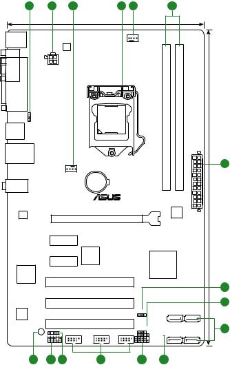
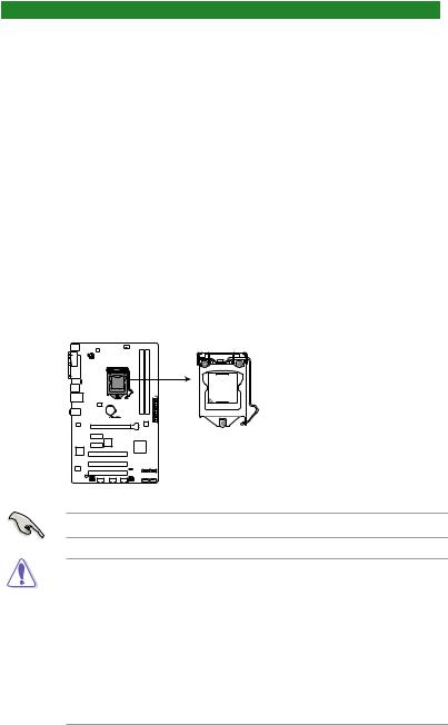
1.4Central Processing Unit (CPU)
The motherboard comes with a surface mount LGA1155 socket designed for the Intel® 3rd / 2nd Generation Core™ i7, i5, i3, Pentium®, and Celeron® processors.
H61-PLUS
H61-PLUS CPU socket LGA1155
Unplug all power cables before installing the CPU.
•Upon purchase of the motherboard, ensure that the PnP cap is on the socket and the socket contacts are not bent. Contact your retailer immediately if the PnP cap is missing, or if you see any damage to the PnP cap/socket contacts/motherboard components. ASUS will shoulder the cost of repair only if the damage is shipment/ transit-related.
•Keep the cap after installing the motherboard. ASUS will process Return Merchandise
Authorization (RMA) requests only if the motherboard comes with the cap on the
LGA1155 socket.
•The product warranty does not cover damage to the socket contacts resulting from incorrect CPU installation/removal, or misplacement/loss/incorrect removal of the PnP cap.
1-8 |
Chapter 1: Product introduction |
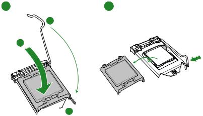
1.4.1CPU installation
The LGA1156 CPU is not compatible with the LGA1155 socket. DO NOT install an LGA1156 CPU on the LGA1155 socket.
1


 A
A
A
B
2 |
3 |
ASUS H61-PLUS |
1-9 |
4 |
5 |
C
A


 B
B
1-10 |
Chapter 1: Product introduction |

1.4.2CPU heatsink and fan assembly installation
Apply the Thermal Interface Material to the CPU heatsink and CPU before you install the heatsink and fan if necessary.
To install the CPU heatsink and fan assembly
1 A 2
B
B 
A
3 |
4 |
ASUS H61-PLUS |
1-11 |
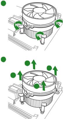
To uninstall the CPU heatsink and fan assembly 1
2 |
A |
|
|
|
B |
|
B |
|
A |
1-12 |
Chapter 1: Product introduction |
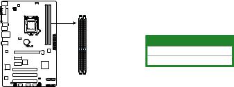
1.5System memory
1.5.1Overview
This motherboard comes with two Double Data Rate 3 (DDR3) Dual Inline Memory Modules (DIMM) sockets.
A DDR3 module has the same physical dimensions as a DDR2 DIMM but is notched differently to prevent installation on a DDR2 DIMM socket. DDR3 modules are developed for better performance with less power consumption.
The figure illustrates the location of the DDR3 DIMM sockets:
H61-PLUS
DIMM_A1 DIMM_B1
Channel |
Sockets |
Channel A |
DIMM_A1 |
Channel B |
DIMM_B1 |
H61-PLUS 240-pin DDR3 DIMM sockets
ASUS H61-PLUS |
1-13 |
1.5.2Memory configurations
You may install 1GB, 2GB, 4GB, and 8GB unbuffered non-ECC DDR3 DIMMs into the DIMM sockets.
•You may install varying memory sizes in ChannelAand Channel B. The system maps the total size of the lower-sized channel for the dual-channel configuration.Any excess memory from the higher-sized channel is then mapped for single-channel operation.
•Always install DIMMs with the same CAS latency. For optimal compatibility, we recommend that you install memory modules of the same version or date code (D/C) from the same vendor. Check with the retailer to get the correct memory modules.
•Memory module with memory frequency higher than 2133 MHz and its corresponding timing or the loaded XMP Profile is not the JEDEC memory standard. The stability and compatibility of these memory modules depend on the CPU's capabilities and other installed devices.
•Due to the memory address limitation on 32-bit Windows® OS, when you install 4GB or more memory on the motherboard, the actual usable memory for the OS can be about 3GB or less. For effective use of memory, we recommend that you do any of the following:
-Use a maximum of 3GB system memory if you are using a 32-bit Windows® OS.
-Install a 64-bit Windows® OS when you want to install 4GB or more on the motherboard.
•This motherboard does not support DIMMs made up of 512Mb (64MB) chips or less.
• The default memory operation frequency is dependent on its Serial Presence Detect (SPD), which is the standard way of accessing information from a memory module. Under the default state, some memory modules for overclocking may operate at a lower frequency than the vendor-marked value. To operate at the vendor-marked
or at a higher frequency, refer to section 2.4 Ai Tweaker menu for manual memory frequency adjustment.
•For system stability, use a more efficient memory cooling system to support a full memory load (2 DIMMs) or overclocking condition.
H61-PLUS Motherboard Qualified Vendors Lists (QVL)
DDR3 2400 (O.C.) MHz capability
Vendors |
Part No. |
Size |
SS/ |
Chip |
Chip NO. |
Timing |
Voltage |
DIMM socket |
|
support (Optional) |
|||||||||
|
|
|
DS |
Brand |
|
|
|
1 DIMM |
2 DIMMs |
CORSAIR |
CMGTX8(XMP) |
8GB(2GB x 4) |
SS |
- |
- |
10-12-10-27 |
1.65V |
• |
• |
G.SKILL |
F3-19200CL11Q-16GBZHD(XMP1.3) |
16GB(4GB x 4) |
DS |
- |
- |
11-11-11-31 |
1.65V |
• |
• |
G.SKILL |
F3-19200CL9D-4GBPIS(XMP) |
4GB(2x 2GB) |
DS |
- |
- |
9-11-9-28 |
1.65V |
• |
• |
GEIL |
GET34GB2400C9DC(XMP) |
2GB |
DS |
- |
- |
9-11-9-27 |
1.65V |
• |
• |
KINGMAX |
FLLE88F-C8KKAA HAIS(XMP) |
2GB |
SS |
- |
- |
10-11-10-30 |
1.8V |
• |
• |
Transcend |
TX2400KLU-4GK(427652)(XMP) |
4GB(2 x 2GB) |
SS |
- |
- |
- |
1.65V |
• |
• |
Transcend |
TX2400KLU-4GK (381850)(XMP) |
4GB(2x 2GB) |
SS |
- |
- |
9 |
1.65V |
• |
• |
Transcend |
TX2400KLU-4GK(374243)(XMP) |
4GB(2x 2GB) |
DS |
- |
- |
9 |
1.65V |
• |
• |
PATRIOT |
PVV34G2400C9K(XMP) |
4GB(2x 2GB) |
DS |
- |
- |
9-11-9-27 |
1.65V |
• |
• |
• DDR3 1600 MHz and higher memory frequency is supported by Intel® 3rd generation processors.
•Due to the CPU behavior, DDR3 2133/1866 memory modules runs at DDR3
2000/1800 MHz frequencies.
1-14 |
Chapter 1: Product introduction |
 Loading...