


 Loading...
H81M-R
<![endif]>Motherboard

E9548
First Edition
July 2014
Copyright © 2014 ASUSTeK COMPUTER INC. All Rights Reserved.
No part of this manual, including the products and software described in it, may be reproduced, transmitted, transcribed, stored in a retrieval system, or translated into any language in any form or by any means, except documentation kept by the purchaser for backup purposes, without the express written permission of ASUSTeK COMPUTER INC. (“ASUS”).
Product warranty or service will not be extended if: (1) the product is repaired, modified or altered, unless such repair, modification of alteration is authorized in writing by ASUS; or (2) the serial number of the product is defaced or missing.
ASUS PROVIDES THIS MANUAL “AS IS” WITHOUT WARRANTY OF ANY KIND, EITHER EXPRESS OR IMPLIED, INCLUDING BUT NOT LIMITED TO THE IMPLIED WARRANTIES OR CONDITIONS OF MERCHANTABILITY OR FITNESS FOR A PARTICULAR PURPOSE. IN NO EVENT SHALL ASUS, ITS DIRECTORS, OFFICERS, EMPLOYEES OR AGENTS BE LIABLE FOR ANY INDIRECT, SPECIAL, INCIDENTAL, OR CONSEQUENTIAL DAMAGES (INCLUDING DAMAGES FOR LOSS OF PROFITS, LOSS OF BUSINESS, LOSS OF USE OR DATA, INTERRUPTION OF BUSINESS AND THE LIKE), EVEN IF ASUS HAS BEEN ADVISED OF THE POSSIBILITY OF SUCH DAMAGES ARISING FROM ANY DEFECT OR ERROR IN THIS MANUAL OR PRODUCT.
SPECIFICATIONS AND INFORMATION CONTAINED IN THIS MANUAL ARE FURNISHED FOR INFORMATIONAL USE ONLY, AND ARE SUBJECT TO CHANGE AT ANY TIME WITHOUT NOTICE, AND SHOULD NOT BE CONSTRUED AS A COMMITMENT BY ASUS. ASUS ASSUMES NO RESPONSIBILITY OR LIABILITY FOR ANY ERRORS OR INACCURACIES THAT MAY APPEAR IN THIS MANUAL, INCLUDING THE PRODUCTS AND SOFTWARE DESCRIBED IN IT.
Products and corporate names appearing in this manual may or may not be registered trademarks or copyrights of their respective companies, and are used only for identification or explanation and to the owners’ benefit, without intent to infringe.
Offer to Provide Source Code of Certain Software
This product contains copyrighted software that is licensed under the General Public License (“GPL”), under the Lesser General Public License Version (“LGPL”) and/or other Free Open Source Software Licenses. Such software in this product is distributed without any warranty to the extent permitted by the applicable law. Copies of these licenses are included in this product.
Where the applicable license entitles you to the source code of such software and/or other additional data, you may obtain it for a period of three years after our last shipment of the product, either
(1)for free by downloading it from http://support.asus.com/download
or
(2)for the cost of reproduction and shipment, which is dependent on the preferred carrier and the location where you want to have it shipped to, by sending a request to:
ASUSTeK Computer Inc.
Legal Compliance Dept.
15 Li Te Rd.,
Beitou, Taipei 112
Taiwan
In your request please provide the name, model number and version, as stated in the About Box of the product for which you wish to obtain the corresponding source code and your contact details so that we can coordinate the terms and cost of shipment with you.
The source code will be distributed WITHOUT ANY WARRANTY and licensed under the same license as the corresponding binary/object code.
This offer is valid to anyone in receipt of this information.
ASUSTeK is eager to duly provide complete source code as required under various Free Open Source Software licenses. If however you encounter any problems in obtaining the full corresponding source code we would be much obliged if you give us a notification to the email address gpl@asus.com, stating the product and describing the problem (please DO NOT send large attachments such as source code archives, etc. to this email address).
ii

Contents
Safety information...................................................................................................... |
iv |
About this guide.......................................................................................................... |
iv |
Package contents....................................................................................................... |
vi |
H81M-R specifications summary............................................................................... |
vi |
Product introduction
1.1 |
Before you proceed...................................................................................... |
1-1 |
1.2 |
Motherboard overview.................................................................................. |
1-1 |
1.3 |
Central Processing Unit (CPU).................................................................... |
1-4 |
1.4 |
System memory............................................................................................ |
1-7 |
1.6 |
Jumpers....................................................................................................... |
1-11 |
1.7 |
Connectors.................................................................................................. |
1-12 |
1.9 |
Software support......................................................................................... |
1-20 |
BIOS information
2.1 |
Managing and updating your BIOS |
.............................................................2-1 |
2.2 |
BIOS setup program..................................................................................... |
2-6 |
2.3 |
My Favorites.................................................................................................. |
2-9 |
2.4 |
Main menu................................................................................................... |
2-10 |
2.5 |
Ai Tweaker menu......................................................................................... |
2-11 |
2.6 |
Advanced menu.......................................................................................... |
2-12 |
2.7 |
Monitor menu.............................................................................................. |
2-13 |
2.8 |
Boot menu................................................................................................... |
2-14 |
2.9 |
Tools menu.................................................................................................. |
2-15 |
2.10 |
Exit menu..................................................................................................... |
2-15 |
Appendices
Notices...................................................................................................................... |
A-1 |
ASUS contact information...................................................................................... |
A-3 |
iii

Safety information
Electrical safety
•To prevent electrical shock hazard, disconnect the power cable from the electrical outlet before relocating the system.
•When adding or removing devices to or from the system, ensure that the power cables for the devices are unplugged before the signal cables are connected. If possible, disconnect all power cables from the existing system before you add a device.
•Before connecting or removing signal cables from the motherboard, ensure that all power cables are unplugged.
•Seek professional assistance before using an adapter or extension cord. These devices could interrupt the grounding circuit.
•Ensure that your power supply is set to the correct voltage in your area. If you are not sure about the voltage of the electrical outlet you are using, contact your local power company.
•If the power supply is broken, do not try to fix it by yourself. Contact a qualified service technician or your retailer.
Operation safety
•Before installing the motherboard and adding devices on it, carefully read all the manuals that came with the package.
•Before using the product, ensure all cables are correctly connected and the power cables are not damaged. If you detect any damage, contact your dealer immediately.
•To avoid short circuits, keep paper clips, screws, and staples away from connectors, slots, sockets and circuitry.
•Avoid dust, humidity, and temperature extremes. Do not place the product in any area where it may become wet.
•Place the product on a stable surface.
•If you encounter technical problems with the product, contact a qualified service technician or your retailer.
About this guide
This user guide contains the information you need when installing and configuring the motherboard.
How this guide is organized
This guide contains the following parts:
•Chapter 1: Product introduction
This chapter describes the features of the motherboard and the new technology it supports.
•Chapter 2: BIOS information
This chapter tells how to change system settings through the BIOS Setup menus. Detailed descriptions of the BIOS parameters are also provided.
iv
Where to find more information
Refer to the following sources for additional information and for product and software updates.
1.ASUS websites
The ASUS website provides updated information on ASUS hardware and software products. Refer to the ASUS contact information.
2.Optional documentation
Your product package may include optional documentation, such as warranty flyers, that may have been added by your dealer. These documents are not part of the standard package.
Conventions used in this guide
To ensure that you perform certain tasks properly, take note of the following symbols used throughout this manual.
DANGER/WARNING: Information to prevent injury to yourself when trying to complete a task.
CAUTION: Information to prevent damage to the components when trying to complete a task
IMPORTANT: Instructions that you MUST follow to complete a task. |
. |
NOTE: Tips and additional information to help you complete a task.
Typography
Bold text |
Indicates a menu or an item to select. |
Italics |
Used to emphasize a word or a phrase. |
<Key> |
Keys enclosed in the less-than and greater-than sign |
|
means that you must press the enclosed key. |
|
Example: <Enter> means that you must press the Enter or |
|
Return key. |
<Key1> + <Key2> + <Key3> |
If you must press two or more keys simultaneously, the key |
|
names are linked with a plus sign (+). |
v
Package contents
Check your motherboard package for the following items.
Motherboard |
ASUS H81M-R motherboard |
|
|
|
|
Cables |
2 x Serial ATA 6.0 Gb/s cables |
|
|
|
|
Accessories |
1 x I/O Shield |
|
|
|
|
Application DVD |
Support DVD |
|
|
|
|
Documentation |
User Guide |
|
|
|
|
|
|
|
If any of the above items is damaged or missing, contact your retailer.
H81M-R specifications summary
CPU |
LGA1150 socket for the 4th Generation and New 4th Generation Intel® |
|
CoreTM i7/ i5 / i3, Pentium® and Celeron® Processors |
|
Supports 22nm CPU |
|
Supports Intel® Turbo Boost Technology 2.0* |
|
* Intel® Turbo Boost Technology 2.0 support depends on the CPU types. |
|
** Refer to www.asus.com for Intel® CPU support list. |
Chipset |
Intel® H81 Express Chipset |
Memory |
2 x DIMMs, max. 16GB DDR3 1600/1333/1066MHz, non-ECC, unbuffered |
|
memory modules |
|
Dual-channel memory architecture |
|
Supports Intel® Extreme Memory Profile (XMP) |
|
* Hyper DIMM support is subject to the physical characteristics of individual |
|
CPUs. Please refer to Memory QVL for details. |
|
** Refer to www.asus.com for the latest Memory QVL (Qualified Vendors List). |
|
*** Due to Intel® chipset limitations, DDR3 1600MHz and higher memory modules |
|
on XMP mode will run at the maximum transfer rate of DDR3 1600MHz. |
Graphics
Expansion slots
Storage
Integrated Graphics Processor - Intel® HD Graphics support Multi-VGA output support: DVI-D, D-Sub port
-Supports DVI-D with max. resolution up to 1920 x1200@60Hz
-Supports D-Sub with max. resolution 1920x1200@60Hz
-Maximum shared memory of 1024MB
1 x PCI Express x16 slot
1 x PCI Express x1 slot
Intel® H81 Express Chipset:
-2 x Serial ATA 6.0 Gb/s connectors (yellow)
-2 x Serial ATA 3.0 Gb/s connectors (dark brown)
-Supports Intel® Rapid Start Technology* and Intel® Smart Connect Technology**
*Due to the limitation of the Intel® H81 chipset, Intel® Rapid Start Technology can be configured only from the BIOS Setup program.
**These functions will work depending on the CPU installed.
(continued on the next page)
vi

H81M-R specifications summary
LAN |
Realtek® RTL8111GR Gigabit LAN Controller |
Audio |
Realtek® ALC887 8-Channel High Definition Audio CODEC |
|
- Supports Jack-Detection and Front Panel Jack-Retasking |
|
* Use a chassis with HD audio module in the front panel to support an |
|
8-channel audio output |
USB
ASUS unique features
Back Panel I/O ports
Internal
I/O connectors/ buttons/switches
Intel® H81 Express Chipset - supports ASUS USB 3.0 Boost
- 2 x USB 3.0/2.0 ports at rear panel (blue)*
Intel® H81 Express Chipset
- 6 x USB 2.0/1.1 ports (4 ports at mid-board, 2 ports at the rear panel)
ASUS Exclusive Features:
-ASUS EPU
-ASUS UEFI BIOS EZ Mode featuring a friendly graphical user interface
-ASUS GPU Boost
-ASUS Ai Charger
-ASUS AI Suite 3
-ASUS Anti-surge Protection
-ASUS ESD
ASUS Quiet Thermal Solution
- ASUS Fan Xpert
ASUS EZ DIY:
-ASUS CrashFree BIOS 3
-ASUS EZ Flash 2
1 x PS/2 keyboard port (purple)
1 x PS/2 mouse port (green)
2 x USB 3.0/2.0 ports
2 x USB 2.0/1.1 ports
1 x DVI port
1 x D-Sub port
1 x LAN (RJ-45) port
3 x Audio jacks support 8-channel audio output
2 x USB 2.0/1.1 connectors support additional 4 USB 2.0/1.1 ports 2 x SATA 6.0Gb/s connectors
2 x SATA 3.0Gb/s connectors
1 x 4-pin CPU fan connector (PWM mode)
1 x 4-pin Chassis fan connector (PWM mode) 1 x Front panel audio connector
1 x 24-pin EATX power connector
1 x 4-pin EATX 12V power connector
1 x COM header
1 x LPT header
1 x TPM header
1 x CLRTC header
1 x Chassis Intrusion header
1 x Speaker connector
1 x System panel connector
(continued on the next page)
vii

H81M-R specifications summary
BIOS features
Manageability
Support DVD
Operating System
Support
Form factor
64 Mb Flash ROM, UEFI AMI BIOS, PnP, DMI2.0, WfM2.0, SM BIOS 2.7, ACPI 2.0a, Multi-language BIOS, ASUS EZ Flash 2, ASUS CrashFree
BIOS 3, My Favorites, Quick Note, Last Modified log, F12 PrintScreen, F3
Shortcut functions and ASUS DRAM SPD (Serial Presence Detect) memory information
WfM 2.0, DMI 2.0, WOL by PME, PXE
Drivers
ASUS utilities
EZ Update
Anti-virus software (OEM version)
Windows® 8.1
Windows® 8
Windows® 7
uATX form factor: 7.5 in x 7.0 in (19 cm x 17.7 cm)
Specifications are subject to change without notice.
viii
Product introduction |
1 |
1.1Before you proceed
Take note of the following precautions before you install motherboard components or change any motherboard settings.
• Unplug the power cord from the wall socket before touching any component.
•Before handling components, use a grounded wrist strap or touch a safely grounded object or a metal object, such as the power supply case, to avoid damaging them due to static electricity.
•Hold components by the edges to avoid touching the ICs on them.
•Whenever you uninstall any component, place it on a grounded antistatic pad or in the bag that came with the component.
•Before you install or remove any component, ensure that the ATX power supply is switched off or the power cord is detached from the power supply. Failure to do so may cause severe damage to the motherboard, peripherals, or components.
1.2Motherboard overview
Before you install the motherboard, study the configuration of your chassis to ensure that the motherboard fits into it.
Ensure that you unplug the power cord before installing or removing the motherboard. Failure to do so can cause you physical injury and damage motherboard components.
1.2.1Placement direction
When installing the motherboard, ensure that you place it into the chassis in the correct orientation. The edge with external ports goes to the rear part of the chassis as indicated in the image below.
ASUS H81M-R |
1-1 |
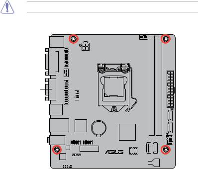
1.2.2Screw holes
Place four screws into the holes indicated by circles to secure the motherboard to the chassis.
Do not overtighten the screws! Doing so can damage the motherboard.
Place this side towards the rear of the chassis
H81M-R |
|
|
|
|
|
|
|
|
|
|
|
|
1-2 |
|
Chapter 1: Product introduction |
|
1.2.3Motherboard layout
1 |
2 |
3 |
4 |
5 |
2 |
6 |
|
|
|
|
17.7cm(7.0in) |
|
|
KBMS |
|
|
|
|
CPU_FAN |
|
|
|
ATX12V |
|
|
|
|
| <![if ! IE]> <![endif]>DVI |
<![if ! IE]> <![endif]>TPM |
|
|
|
<![if ! IE]> <![endif]>module) |
<![if ! IE]> <![endif]>module) |
|
CHA_FAN |
|
|
|||
|
|
|
<![if ! IE]> <![endif]>240-pin |
<![if ! IE]> <![endif]>240-pin |
||
| <![if ! IE]> <![endif]>VGA |
<![if ! IE]> <![endif]>LPT |
|
|
|
||
|
|
LGA1150 |
<![if ! IE]> <![endif]>(64bit,A1 |
<![if ! IE]> <![endif]>(64bit,B1 |
||
|
|
|
|
|
|
|
|
|
|
|
|
<![if ! IE]> <![endif]>_ |
<![if ! IE]> <![endif]>_ |
|
COM |
|
|
|
<![if ! IE]> <![endif]>DIMM |
<![if ! IE]> <![endif]>DIMM |
USB3_12 |
|
|
|
|
<![if ! IE]> <![endif]>DDR3 |
<![if ! IE]> <![endif]>DDR3 |
15
LAN_USB34 |
Super |
|
|
I/O |
|
|
|
|
BATTERY |
Intel® |
|
14 |
|
|
|
USB56 USB910 |
|
H81 |
|
AUDIO |
|
|
|
|
|
|
Realtek® |
|
PCIEX1_1 |
|
8111GR |
|
64Mb |
|
|
|
|
BIOS |
887 |
CHASSIS |
|
H81M-R |
ALC |
|
|
|
AAFP |
PCIEX16 |
|
|
|
|
|
|
<![if ! IE]> <![endif]>CLRTC |
|
|
|
<![if ! IE]> <![endif]>F PANEL |
| <![if ! IE]> <![endif]>SATA3G 1 |
|
|
|
|
<![if ! IE]> <![endif]>SATA3G 2 |
<![if ! IE]> <![endif]>SPEAKER |
|
|
||
|
|
|
|
|
|
|
|
|||
|
|
|
|
|
|
|
||||
|
|
|
|
|
|
|
|
|
|
|
|
|
|
|
|
|
|
|
|
|
|
3
<![if ! IE]><![endif]>19cm(7.5in)

 7
7
8 9 10 11
1312
1.2.4Layout contents
Connectors/Jumpers/Slots/LED |
Page |
|
1. |
TPM header (20-1 pin TPM) |
1-19 |
2. |
CPU and chassis fan connectors (4-pin CPU_FAN, 4-pin CHA_FAN) |
1-15 |
3. |
ATX power connectors (24-pin EATXPWR, 4-pin ATX12V) |
1-16 |
4.LPT connector (26-1 pin LPT)
|
5. |
Intel® LGA1150 CPU socket |
1-3 |
|
|
6. |
DDR3 DIMM slots |
1-7 |
|
|
7. |
Intel® H81 Serial ATA 6.0Gb/s connector (7-pin SATA6G_1~2 [yellow]) |
1-17 |
|
|
8. |
Clear RTC RAM (2-pin CLRTC) |
1-11 |
|
|
9. |
System panel connector (10-1 pin F_PANEL) |
1-19 |
|
|
10. |
Speaker connector (4-pin SPEAKER) |
1-16 |
|
|
11. |
Intel® H81 Serial ATA 3.0Gb/s connector (7-pin SATA3G_1~2 [dark brown]) |
1-17 |
|
|
12. |
Chassis intrusion connector (4-1 pin CHASSIS) |
|
|
|
13. |
Front panel audio connector (10-1 pin AAFP) |
1-14 |
|
|
14. |
USB 2.0 connectors (10-1 pin USB78, USB56) |
1-15 |
|
|
15. |
Serial port connectors (10-1 pin COM) |
1-14 |
|
ASUS H81M-R |
1-3 |
1.3Central Processing Unit (CPU)
This motherboard comes with a surface mount LGA1150 socket designed for the Intel® 4th generation Core™ i7 / Core™ i5 / Core™ i3, Pentium® and Celeron® processors.
H81M-R
H81M-R CPU socket LGA1150
Unplug all power cables before installing the CPU.
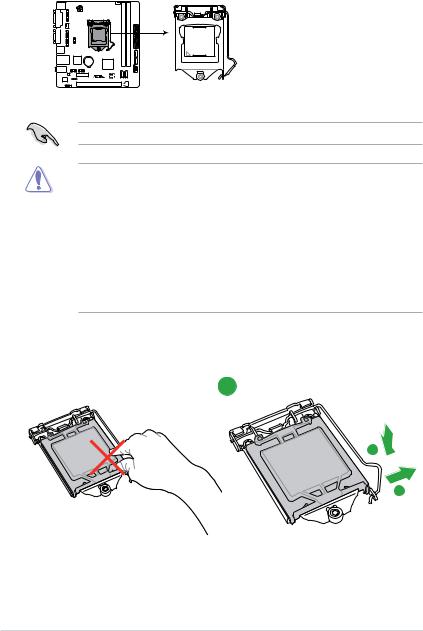
•Upon purchase of the motherboard, ensure that the PnP cap is on the socket and
the socket contacts are not bent. Contact your retailer immediately if the PnP cap is missing, or if you see any damage to the PnP cap/socket contacts/motherboard components. ASUS will shoulder the cost of repair only if the damage is shipment/ transit-related.
•Keep the cap after installing the motherboard. ASUS will process Return Merchandise Authorization (RMA) requests only if the motherboard comes with the cap on the
LGA1150 socket.
•The product warranty does not cover damage to the socket contacts resulting from incorrect CPU installation/removal, or misplacement/loss/incorrect removal of the PnP cap.
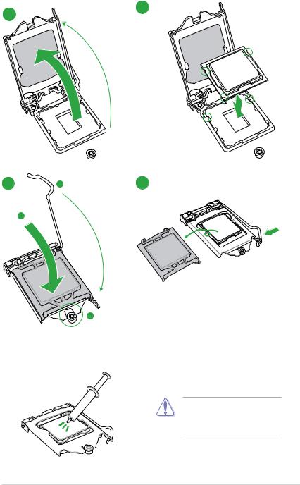
1.3.1Installing the CPU
1
A
B
1-4 |
Chapter 1: Product introduction |
2
4
C
A
3
5
1.3.2CPU heatsink and fan assembly installation
Apply the Thermal Interface Material to the CPU heatsink and CPU before you install the heatsink and fan if necessary.
ASUS H81M-R |
1-5 |

To install the CPU heatsink and fan assembly
1 |
A |
2 |
|
|
B
B
A
3 |
4 |
To uninstall the CPU heatsink and fan assembly
1 

 2 A
2 A 
B
B
A
1-6 |
Chapter 1: Product introduction |
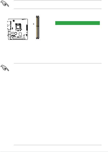
1.4System memory
1.4.1Overview
This motherboard comes with two Double Data Rate 3 (DDR3) Dual Inline Memory Module (DIMM) sockets. A DDR3 module is notched differently from a DDR or DDR2 module. DO NOT install a DDR or DDR2 memory module to the DDR3 slot.
According to Intel® CPU spec, DIMM voltage below 1.65V is recommended to protect the CPU.
<![if ! IE]><![endif]>DIMM_B1
<![if ! IE]><![endif]>DIMM_A1
|
|
|
|
|
|
|
|
|
|
|
|
|
|
|
|
|
|
|
|
|
|
|
|
|
|
|
|
|
|
|
|
|
|
|
|
|
|
|
|
|
|
|
|
|
|
|
|
|
|
|
|
|
|
|
|
|
|
|
|
|
|
|
|
Channel |
Sockets |
|
|
|
|
|
|
|
|
|
|
|
|
|
|
|
|
|
|
|
|
Channel A |
DIMM_A1 |
|
|
|
|
|
|
|
|
|
|
|
|
|
|
|
|
|
|
|
|
Channel B |
DIMM_B1 |
|
|
|
|
|
|
|
|
|
|
|
|
|
|
|
|
|
|
|
|
||
|
|
|
|
|
|
|
|
|
|
|
|
|
|
|
|
|
|
|
|
|
|
|
|
|
|
|
|
|
|
|
|
|
|
|
|
|
|
|
|
|
|
|
|
|
|
|
|
|
|
|
|
|
|
|
|
|
|
|
|
|
|
|
|
|
|
|
|
|
|
|
|
|
|
|
|
|
|
|
|
|
|
|
|
|
|
|
|
H81M-R
H81M-R 240-pin DDR3 DIMM sockets
1.4.2Memory configurations
You may install 1GB, 2GB, 4GB, and 8GB unbuffered non ECC DDR3 DIMMs into the DIMM sockets.
•You may install varying memory sizes in Channel A and Channel B. The system maps the total size of the lower-sized channel for the dual-channel configuration. Any excess memory from the higher-sized channel is then mapped for single-channel operation.
•Due to Intel® chipset limitations, DDR3 1600MHz and higher memory modules on XMP mode will run at the maximum transfer rate of DDR3 1600MHz.
•Always install DIMMs with the same CAS latency. For optimal compatibility, we recommend that you install memory modules of the same version or date code (D/C) from the same vendor. Check with the retailer to get the correct memory modules.
•Due to the memory address limitation on 32-bit Windows® OS, when you install 4GB or more memory on the motherboard, the actual usable memory for the OS can be about 3GB or less. For effective use of memory, we recommend that you do any of the following:
-Use a maximum of 3GB system memory if you are using a 32-bit Windows® OS.
-Install a 64-bit Windows® OS if you want to install 4GB or more on the motherboard.
•This motherboard does not support DIMMs made up of 512 megabits (Mb) chips or less.
•Memory modules with memory frequency higher than 2133 MHz and its corresponding timing or the loaded X.M.P. Profile is not the JEDEC memory standard. The stability and compatibility of these memory modules depend on the CPU’s capabilities and other installed devices.
•The maximum 16GB memory capacity can be supported with 8GB or above DIMMs.
ASUS will update the memory QVL once the DIMMs are available in the market.
ASUS H81M-R |
1-7 |
Loading...