

Page 1
Page 2

ONLY FOR THE CATALYTIC VERSION
USE ONLY UNLEADED PETROL IN CONFORMITY WITH THE DIN 51607 STANDARD, MIN. O.N. 95
(N.O.R.M.) AND 85 (N.O.M.M.) AND HIGH PERFORMANCE SYNTHETIC OIL FOR 2 STROKE ENGINES.
THE USE OF FUELS AND LUBRICANTS DIFFERENT FROM THOSE INDICATED CAUSES SEVERE
FUNCTIONAL INCONVENIENCES TO THE VEHICLE AND THE VOIDING OF THE
ONLY FOR THE CATALYTIC VERSION
To have the catalytic converter functioning correctly for long periods and to reduce possible
problems regarding the contamination of the thermal unit and of the exhaust, it is necessary to
avoid covering long distances with the engine running at constantly low rpm.
a
It is sufficient to alternate these periods with periods in which the engine runs at relatively high rpm,
even if only for a few seconds, but rather frequently.
What has been stated above assumes particular importance for the cold starting of the engine: in this
case, in order to reach a rpm regime sufficient to enable the “priming” of the catalytic reaction, you just
need to make sure that the temperature of the thermal unit has reached at least 50°C, which generally
occurs a few seconds after starting the engine.
aprilia
GUARANTEE.
1
Page 3

CATALYTIC SILENCER
The catalytic version of the RX50 is fitted with a silencer with metal catalytic converter of the “platinumrhodium bivalent” type. This device provides for the oxidation of the CO (carbon monoxide) and of the
HC (unburned hydrocarbons) contained in the exhaust gases, changing them into carbon dioxide and
steam, respectively. Due to the catalytic reaction, the high temperature reached by the exhaust gases
results in the burning of the oil particles, thus keeping the silencer clean and eliminating the exhaust
fumes.
Avoid parking the catalytic vehicle near dry brush wood or in places easily accessible to children, as the catalytic silencer becomes extremely hot during use; be very careful and avoid any
kind of contact before it has completely cooled down.
a
2
Page 4
First edition: february 1996
Reprint: september 1996, march 1997, april 1998
Produced and printed by:
Studio Tecno Public
Viale del Progresso - 37038 Soave (VR) - Italy
Tel. +39 - 045 76 11 911
Fax +39 - 045 76 12 241
www.stp.it
E-mail: customer@stp.it
On behalf of:
aprilia s.p.a.
via G. Galilei, 1 - 30033 Noale (VE) - Italy
Tel. +39 - 041 58 29 111
Fax +39 - 041 44 10 54
www.aprilia.com
This manual contains all the main information and the
instructions required for normal use and maintenance
of your vehicle.
For controls and check-ups that cannot be carried out
easily with the standard equipment supplied, we advise you to consult our Dealers who can assure you
of quick and careful servicing.
To keep your
aprilia vehicle always in perfect operat-
ing conditions, we advise you to insist on Original
Spares and to have repairs carried out only by
aprilia
Authorized Outlets and Official Dealers.
When ordering spare parts from the Dealers, always
quote the spares code which is stamped on a sticker
placed under the saddle.
It is a good idea to make a note of the identification
code in the space provided in this manual, so that
you will always have a record of it even if the identification sticker comes off.
aprilia
GR NL CH DK J SGP PL IL ROK
MAL RCH BM USA AUS
CODICE RICAMBI spare parts code number
ABCDE
N˚
IUKAPSFB D F E
I.M.
All information is purely indicative and may be subject to variation without notice.
3
Page 5

Carefully observe the instructions preceded by the
following warning signs:
Safety norms and regulations to protect
the driver and other people from severe
injuries or grave risks
a
Caution norms and suggestions to avoid
damaging the vehicle and/or hurting yourself or other people
b
Indications to make the operations easier.
c
Technical information
automatic light switching version
_
(Automatic Switch-on Device)
catalytic version
2
Italy version
I
United Kingdom version
U
Austria version
A
Portugal version
P
Finland version
"
Belgium version
B
Germany version
D
France version
F
Spain version
E
Greece version
G
Holland version
O
Switzerland version
C
4
.
.
.
Denmark version
£
Japan version
J
Singapore version
S
Poland version
V
Israel version
%
South Korea version
K
Malaysia version
M
Chile version
R
Bermuda version
Q
United States
-
of America version
Australia version
^
CONTENTS
Pag.
Technical features ....................................................5
Identification data.....................................................8
Arrangement of the controls.....................................9
Instructions for use.................................................12
Maintenance...........................................................15
Electrical system ....................................................35
Cleaning.................................................................40
Long inactivity ........................................................40
Periodic maintenance chart....................................41
Lubricant chart .......................................................42
Importers................................................................43
Wiring diagram.......................................................45
Page 6

TECHNICAL FEATURES
MOTOR
Model..................................................................AM6
Type......................................2 stroke single-cylinder
with lamellar inlet
Cooling..........................Liquid with forced circulation
Lubrication .................................................. Separate
Bore / stroke...................................40,3 mm / 39 mm
Displacement ............................................ 49,75 cmC
Compression ratio.............................................12 : 1
KICK START
To pedal (Kick-starter)
CLUTCH
Light alloy multiple disc oil bath
GEARS
Frontal clutch 6 speed unit
TRANSMISSION
Primary ........................................ Helical teeth gears
Ratio 3,55 (Z=20/71)
Secondary.........chain 1/2"x3,16" = Roller Ø7,75 mm
Ratio: 4,25 (Z=12/51)
CARBURETTOR
Model .................................................. Dell’Orto SHA
Diffuser...................................................Ø 12-14 mm
AIR FILTER
Sponge
IGNITION
Type........................................................... electronic
Spark advance reference...............................1,5 mm
correspondent to 20° before T.D.C.
Spark plug............................................NGK BR8 ES
FUEL
Running-in (500 km) .........................unleaded petrol
according to the DIN 51607 standard
min. O.N. 95 (N.O.R.M.)
and 85 (N.O.M.M.)
Aferwords:.........................................unleaded petrol
according to the DIN 51607
min. O.N. 95 (N.O.R.M.)
and 85 (N.O.M.M.)
Fuel tank capacity............................................... 9,5
Reserve (with mechanical operation)..................1,5l
Mixer oil tank capacity......................................... 1,3l
Reserve (with warning light on the dashboard)...0,5l
l
5
Page 7

LUBRICATION
Gearbox and primary transmission 820 cmC of oil (*)
COOLING
Cooling circuit capacity .................................0,9 l (*)
(60% antifreeze + 40% water)
Minimum operating temperature.......................-17°C
FRAME
High-resistance one-beam structure, split over the
exhaust
REAR FORK
Made of rectangular-profile steel, mounted on antifriction bushings
SUSPENSIONS
Front....................................aprilia telehydraulic fork
with reversed rods
with advanced pin, rods Ø 35
stroke 250 mm
Rear ................................aprilia Progressive System
adjustable hydraulic mono-shock absorber
Rear wheel stroke.........................................260 mm
(*) see “LUBRICANT CHART”
BRAKES
Front........................................ disc brake Ø 230 mm
with hydraulic control
and floating caliper with two parallel pins
Rear ........................................ disc brake Ø 220 mm
with hydraulic control
and fixed caliper
with two opposing pins Ø 28 mm
TYRES
Front....................................90/90 x 21" Enduro type
inflation pressure: 1,6 bar
Rear ..................................110/80 x 18" Enduro type
inflation pressure: 1,8 bar
RIMS
Front.............................................................21 x 1,6"
Rear ...........................................................18 x 1,85"
DIMENSIONS
Max. length..................................................2060 mm
Wheelbase (slot center) ..............................1360 mm
Handlebars width ..........................................810 mm
Max. height..................................................1350 mm
Seat height....................................................890 mm
Footboard height...........................................355 mm
6
Page 8

TYRE INFLATION PRESSURE
Kind of drive
Off-road 1,3 bar 1,4 bar
On mixed roads 1,5 bar 1,6 bar
On asphalt
paved roads
Maximum front and rear pressure: 2,5 bar
Driver only
Front Rear
1,6 bar 1,8 bar
Low pressure can cause handling problems and the tendency to weave and in
extreme cases loss of control.
a
Moreover this will cause a great increase of rolling friction.
The results are: high consumption of fuel and reduced maximum speed.
The disadvantage may cause a damage of the cover,
due to excessive local deformation.
Tyre pressure must be checked when the
c
that is, when the vehicle has not been moved in
the last 2 or 3 hours for more than 1 km.
– The tyre should often be inspected for signs of
– Blowings or irregular wavings are showing in-
tyres are at environment temperature,
Check the depth of the tyre tread often, if
it is worn below the allowable limit (2 3 mm.) change the tyre.
a
damage or cuts.
ternal damages, which request the prompt re-
placement of the tyre.
Remember: 1 mile = 1.6 km
c
1 km = 0.625 miles
7
Page 9
IDENTIFICATION DATA
c
It is a good rule to write down the frame and engine
numbers in the space provided in this manual.
The frame number can be used for the purchase of
spare parts.
Do not alter the identification numbers if
administrative sanctions. In particular, the alteration of the frame number results in the immediate
invalidity of the guarantee.
you do not want to incur severe penal and
8
Fig. 1
Fig. 2
FRAME NUMBER (Fig. 1)
The frame number is stamped on the left side of the
steering head.
Frame n°
ENGINE NUMBER (Fig. 2)
The engine number is printed in the space provided
upper the pinion.
Engine n°
Page 10

ARRANGEMENT OF THE CONTROLS
The control devices are positioned as indicated in figures 3 and 4, as follows:
Fig. 3
1) Clutch lever
2) Front brake lever
3) Twist grip
4) Rear brake pedal
5) Kick-starter
6) Gear pedal
Fig. 4
1) Turn indicator switch (c)
2) Horn push button (
3) Dimmer light switch (
gnalling push button (
3a)
% _
beam signalling push button (
4) Trip odometer control knob
5) Speedometer/odometer with trip counter
6) Mixer oil reserve warning light (
7) Low beam warning light (
7a) High beam warning light (
8) Neutral indicator warning light (q)
9) Revolution counter (rpm)
10) Turn indicator warning light (
11) Ignition switch / steering lock / light switch
s - m - n - o)
(
c
Dimmer light switch (
Remember: 1 mile = 1.6 km
f)
b - p) and low beam si-
b)
a - b) and high
a)
j)
b)
a)
% _
c)
1 km = 0.625 miles
Fig. 3
Fig. 4
9
Page 11

IGNITION SWITCH / STEERING LOCK /
LIGHT SWITCH
The ignition switch has 4 click positions:
◆ First click clockwise = “n“ (start)
◆ Second click clockwise = “o“ (light on) (not provid-
ed in the
◆ Central position = “m” (stop)
◆ Anticlockwise rotation = “s“ (steering lock)
Position Function Key removal
s
Steering
lock
m
n
o
version).
_
The steering is
locked. It is neither
possible to start the
engine, nor to switch
on the lights.
Neither the engine,
nor the lights can be
switched on.
The engine can be
start.
It is neither possible
to switch the lights.
The engine and the
lights can be
switched on.
It is possible to
remove the key.
It is possible to
remove the key.
It isn't possible
to remove the
key.
It isn't possible
to remove the
key.
AUTOMATIC
LIGHT SWITCHING VERSION
The vehicles provided with the Automatic Switch-on
Device can be immediately recognized, since the
lights come automatically on as soon as the engine is
started.
For this reason the light switch is replaced by a dimmer switch.
The lights can be switched off only by stopping the
engine.
For the versions with high beam, proceed as follows:
◆ Before starting the vehicle, make sure that the
dimmer switch is in position “
STEERING LOCK
Never turn the key to the "s" position
while driving, in order to avoid losing
control of the vehicle.
a
OPERATION
To lock the steering turn the handlebars completely
to the left.
With the key on the "
lease it and turn it to the "
Remove the key.
m" position, press the key, re-
s" position.
_
b” (front low beam).
10
Page 12
CRASH-HELMET LOCK (Fig. 5)
Using the ignition key it is possible to have access to
the crash-helmet lock positioned on the rear part of
the vehicle.
GLOVE / TOOL COMPARTMENT (Fig. 6)
It is positioned on the inner part of the left side of the
fairing.
Fig. 5
Fig. 6
11
Page 13

INSTRUCTIONS FOR USE
c
◆ Before starting the vehicle for the first time, check
that the tyres are inflated to the correct pressure
(Front 1,6 bar - Rear 1,8 bar) and fill the fuel tank
with premium grade petrol (see “TECHNICAL DATA”).
◆ Fill the mixer oil tank with oil (see “LUBRICANT
CHART”).
The motor must not be filled with petrol/
oil mixed at filling stations.
b
◆ Check the engine coolant level (see “COOLANT
CHECKING”).
◆ Make sure that there are no air bubbles in the mix-
er oil pipe (from the oil tank to the pump); if necessary, bleed the pump by means of the appropriate
screw (see "SEPARATE LUBRICATION”).
RUNNING
In the initial period of use is very important for the future performance of the engine.
We advise warming up the engine before starting off,
allowing it to turn over for a few minutes at a low
speed.
If possible, drive on hill roads and/or roads with many
bends, so that the engine, the suspensions and the
brakes undergo a more effective running-in.
After the first 500 km, have the vehicle checked with
the first service coupon by an aprilia Offical Deal-
er.
If there is no oil left in the mixer oil tank,
avoid using the vehicle so as not to cause
irreparable damage to the motor.
b
Then bleed the system (see “SEPARATE LUBRIFICATION”) after filling the tank with specific oil
(see “LUBRICANT CHART).
The disc and shoes of the front brake require a running-in period (about 500 km) before reaching optimum performance conditions.
12
Remember: 1 mile = 1.6 km
1 km = 0.625 miles.
Page 14

STARTING (Fig. 7-8)
◆ Open the fuel coock on the tank (Fig. 7).
◆ Insert the ignition key and turn to “n” position.
◆ If the starting takes place with cold engine, push
the choke lever upwards (Fig. 8).
◆ Place gears in neutral position, (neutral indicator
warning light “
◆ Act on the kick starter with your right foot, releas-
ing it immediately.
q” comes on) or pull on clutch lever.
If the mixer oil reserve warning light "
comes on during the normal running of
the engine, this means that the mixer oil
a
reserve is being used; in this case, provide for
topping up.
Do not continue to press the kickstart lever or attempt to use it while the engine
is running.
b
j"
Fig. 7
Fig. 8
13
Page 15
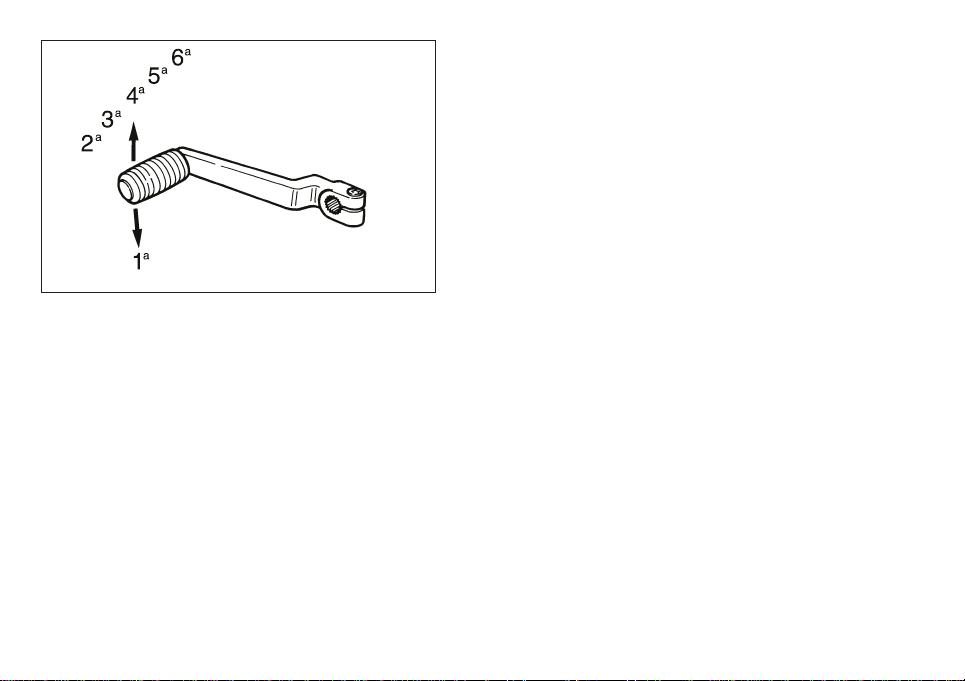
Fig. 9
◆Once you have started the engine, wait for a few
seconds, then twist the throttle, turn the accelerator handle firmly as far as it will go, thus automatically disconnecting the starter (a metallic click will
be heard).
◆When the engine is warm it should be started with-
out using the choke.
The engine must not remain turned on
with the battery or the voltage regulator
disconnected; this would cause irrepara-
b
ble damage to the electrical system.
MOVING OFF (Fig. 9)
After warming up the engine:
◆Pull in the clutch lever.
◆Engage 1st gear (gear pedal downwards).
The neutral indicator warning light “
◆ Then gradually release the clutch and turn the
throttle at the same time.
CHANGING GEAR (Fig. 9)
Release the throttle, pull the clutch lever in and lift the
gear lever upwards to change to the higher gears.
Vice versa, push downwards when changing to a
lower gear.
Before riding the motor cycle we advise
you to get to know the controls and all
their functions as explained in this manu-
a
al. Contact your aprilia Offical Dealer if there is
anything you do not understand.
q” go out.
14
Page 16

STOPPING THE ENGINE
Release the twist grip, set the gear in neutral position, neutral indicator warning light “
turn the ignition key in an ‘‘
Turn off the fuel cock (Fig. 7).
If there should be an excessive coolant
temperature during normal operation,
turn off the engine.
b
Wait for it to cool down, then check the level of
the coolant (see “COOLANT CHECKING”) and
top up if necessary.
If the level is normal have the cooling system
checked by an aprilia Official Dealer.
m'' position.
q” comes on, and
MAINTENANCE
See “PERIODIC MAINTENANCE CHART”.
Before beginning any maintenance operation or any inspection of the vehicle, stop
the engine, extract the key, wait until the
a
engine and the exhaust system have cooled
down and if possible lift up the vehicle by means
of the proper equipment, on firm and flat ground.
Keep away from the red-hot parts of the engine
and of the exhaust system, in order to avoid
burns. The vehicle is made up of not edible parts.
Never bite, suck, chew or swallow any part of the
vehicle for any reason.
If not expressly indicated otherwise, for
the reassembly of the units repeat the disassembly operations in reverse order.
b
Usually ordinary maintenance operations can be carried out by the user, but sometimes a basic knowledge of mechanics and specific tools are required.
If you need assistance or technical advice consult
your aprilia Official Dealer, who can ensure you
quick and careful servicing.
15
Page 17

Fig. 10
CHECKING THE GEAR OIL LEVEL
(Fig. 10)
◆ Hold the vehicle in an upright position with respect
to the ground.
◆ Remove the checking screw (1) (right side cover):
the oil level is correct if it reaches the bottom edge
of the hole when the vehicle in an upright position.
◆ If necessary, top up through the filler hole (2).
GEAR OIL REPLACEMENT (Fig. 10)
This operation should be carried out while the engine
is warm so that the oil drains off faster.
The procedure is as follows.
◆ Unscrew the filler plug (2).
◆ Place a suitably large container (min. 1000 cm C)
under the engine to catch the old oil.
◆ Unscrew the drain plug (3) placed on the bottom.
◆ Once all the oil has drained off, replace the drain
plug (3) and pour 820 cmC of oil into the filler hole
(2) (see “LUBRICANT CHART”).
In case of oil leakages or malfunctions,
contact your aprilia Official Dealer.
DO NOT DISPOSE OF OIL IN THE ENVI-
a
RONMENT.
16
Page 18

CLUTCH ADJUSTMENT (Fig. 11-12)
This model is equipped with two devices for adjusting the length of the clutch cable.
Check the correct adjustment of the clutch cable from
time to time, ensuring that the idle stroke of the control lever is from 3 ÷ 4 mm (Fig. 11).
If this distance is not correct, turn the control lever adjuster (1) or the adjuster on the motor cover (Fig. 12).
If it is not possible to adjust the clutch by
means of the adjusters, contact your
aprilia Official Dealer
a
The clutch must be adjusted when it does not "release" correctly and the vehicle tends to move even
with the clutch pulled.
On the contrary, if the clutch “slips” the acceleration
of the vehicle will not be in proportion to the acceleration of the motor.
Fig. 11
Fig. 12
17
Page 19

Fig. 13
SEPARATE LUBRICATION (Fig. 13-14)
Top up the mixer oil tank every 500 km.
The vehicle has a separate lubrication system which
includes an mixer oil tank (Fig. 13) (1,3
serve of 0,5
pump (the capacity varies according to the number of
revs of the motor and the opening of the throttle).
When the oil reaches reserve level, this is indicated by the coming on of the mixer oil reserve
warning light “
The capacity is predetermined in the design phase,
so there is no need for the user to make any adjustment. It is necessary to bleed air from the pump
whenever it has to be dismantled, the mixer oil supply
pipe is detached, or when the lubricant in the mixer
oil tank is completely exhausted.
Proceed as follows:
◆ Empty the fuel tank and fill it with 2 ÷ 3 l of mixture
containing 1% oil (see “LUBRICANT CHART”).
◆ Start the motor and let it idle.
l ) and a variable-capacity oil supply
j“.
l with a re-
18
Page 20

◆ Unscrew the drainage screw (1) and at the same
time completely rotate the pump control lever (2)
until the oil drains off, then tighten the screw
again.
◆ Keep the pump lever rotated until all traces of air
bubbles have completely disappeared from the
carburettor supply pipe.
For greater safety we advise using up all
the blended fuel in the tank before refilling with only premium grade petrol (see
b
“TECHNICAL FEATURES”).
◆ Adjust the motor idling speed, then check that the
end play of the oil pump and the carburettor cables is the same; if not, regulate the adjusters provided in order to obtain a clearance of 1 mm.
◆ Check that there are no twist in the petrol hose
and oil hose.
If there are twist then replace the hose.
Fig. 14
19
Page 21

Fig. 15
ADJUSTING THE REAR BRAKE (Fig. 15)
The brake pedal is positioned ergonomically during
the assembly phase.
If necessary, it is possible to adjust the height of the
brake pedal:
◆ Loosen the lock nut (1).
◆ Unscrew the brake adjuster completely (2).
◆ Screw the lock nut (3) on the pump control rod (4)
completely.
◆ Screw the pump control rod completely (4), then
unscrew it by giving it 3 - 4 turns.
◆ Screw the brake adjuster (2) until the pedal reach-
es the desired height.
◆ Lock the brake adjuster (2) by means of the lock
nut (1).
◆ Unscrew the pump control rod and bring it in con-
tact with the pump piston.
Make sure that there is a certain clearance between the brake adjuster (2) and
the stroke point, to prevent the brake
b
from remaining in function, which would cause
the untimely wear of the braking elements.
◆ Unscrew the pump control rod (4) and restore the
clearance between the brake adjuster and the
stroke point.
Clearance between brake adjuster and stroke
point: 0,5 ÷ 1 mm.
◆ Lock the pump control rod by means of the lock
nut (3).
Check the braking efficiency.
If necessary, contact your aprilia Official
Dealer.
a
20
Page 22

CHECKING AND BLEEDING THE FRONT
AND REAR BRAKE (Fig. 16)
The vehicle is provided with a hydraulically controlled
front and rear disc brake. The brake fluid level in the
pump tank must be checked from time to time.
◆ After the first 500 km or whenever an excessive
idle stroke of the lever is found, the hydraulic system must be bled to remove any air bubbles that
may have formed.
The bleeding operations for the front and
c
rear braking system are the same.
◆ Remove the protection cap of the caliper breather
valve (1).
◆ Fit one end of a transparent PVC tube (2) over the
end of the caliper breather valve.
◆ The other end of the tube must be placed in a re-
ceptacle to catch the fluid (3).
◆ Remove the lid of the brake fluid pump and check
that the level is correct. If necessary, top up (see
“LUBRICANT CHART”).
◆ Pull the brake lever slowly and completely (2-3
times). Keeping the lever in pulled position, open
the breather valve (1) until fluid and any air bubbles can be seen coming out of the tube.
◆ Close the valve again and release the brake lever.
◆ Repeat the operation described above until no
more air bubbles can be seen in the fluid coming
out of the valve.
Fig. 16
◆ Tighten the valve and remove the tube, being
careful not to get fluid on the brake pads or the
disc.
◆ Reposition the protection cap, top up the reservoir
to maximum level and close it carefully.
After reassembly, pull the front brake lever repeatedly and check the proper functioning of the braking system.
a
Brake fluid is corrosive and can cause damage.
Remember: 1 mile = 1.6 km
c
1 km = 0.625 miles
21
Page 23

CHECKING THE BRAKE PAD WEAR
(Fig. 17-18)
Check the brake pad wear every 3000 km. In order to
check this properly, it is necessary to remove the caliper from the support by unscrewing the screws (1).
The pads present a groove that must always be visible.
If this groove is not visible any more (thickness of
the friction surface = 1,5 mm), change the pads.
22
Fig. 17
Fig. 18
CHANGING THE FORK OIL (Fig. 19)
It is advisable to have this operation performed by an aprilia Official Dealer, who
will ensure qualified and prompt servic-
a
ing.
The fork oil must be changed every 6000 km, or more
frequently if the vehicle is used off-road.
To carry out this operation it is necessary to remove
the front wheel and to withdraw the two fork tube assemblies from the plates.
Right fork tube assembly:
◆ Unscrew and remove the upper plug of the slider
(see figure) and slightly press the slider itself
downwards until the two half-washers can be removed.
Page 24

◆ Bring the slider back to its original position and
slightly lift it until the rod disappears inside the
slider itself.
◆ Turn the fork tube assembly upside down and
drain the oil.
◆ Withdraw the rod from the slider and let it drip for
about half an hour.
◆ Put back the slider on the rod and pour 550 cmC of
oil inside the slider (see "LUBRICANT CHART").
◆ Put back the two half-washers.
◆ Screw the slider plug thoroughly.
Left fork tube assembly:
◆ Unscrew and remove the upper plug of the slider,
remove the two half-washers and lower the rod.
◆ Turn the fork tube assembly upside down and let
all the oil out, then remove the slider.
◆ Push the fork repeatedly downwards until all the
oil has flown out completely. Then put back the
slider.
◆ Center the rod on the upper hole of the slider by
means of a M4 screw of suitable length, then pour
550 cmC of oil (see "LUBRICANT CHART").
◆ Put back the two half-washers.
◆ Screw the upper plug of the slider and tighten it.
Fig. 19
23
Page 25

Fig. 20
ADJUSTING THE REAR SUSPENSION
(Fig. 20)
The rear suspension comprises a single spring-shock
absorber unit and a lever unit with A.P.S.
The standard rear suspension is suitable for a driver
weighing about 75 kg.
If your weight or your needs are different, work on the
length of the shock absorber spring, by acting on the
nut (1) to restore the right driving position.
To check this position:
◆ With the vehicle in an upright position, without the
rider and prop stand, measure the distance (2-3).
◆ With the rider sitting in the riding position (feet on
the footpegs) and the vehicle in vertical position,
measure the distance (2-3) again.
◆ The difference between the two measures (shock
absrober pre-loading) must be included between a
maximum of 75 mm and a minimum of 65 mm.
24
Page 26

CHAIN ADJUSTMENT (Fig. 21)
◆ Stand the vehicle in an upright position and com-
pletely extend the rear suspension.
◆ Check that the vertical movement in the lower part
of the chain, at a point mid-way between the pinion and the crown, is about 40 mm.
If this distance is not correct, proceed as follows:
◆ Loosen the rear wheel pin fastening nut.
For the wheel centering:
Make sure that on both sides the fixed
reference on the rear fork corresponds
b
to the number indicated on the chain tightener.
◆ Act on the apposite chain tighteners.
◆ Once the operation has been performed, tighten
the rear wheel pin fastening nut.
Fig. 21
25
Page 27

26
c
CHAIN LUBRICATION (Fig. 23)
Lubricate the chain frequently (see "LUBRICANT
CHART") about every 1000 km.
Fig. 22
CHAIN CHECKING (Fig. 24)
From time to time check the wear condition of the
chain; make sure that it is not too loose and that there
are no angles or seized links.
If any faults are found, change the chain.
Never fit a new drive chain on a sprocket
wheel/ crown gear with very worn teeth;
vice versa do not use a worn chain on a new
sprocket wheel/crown gear.
Fig. 23
Page 28

AIR FILTER REMOVING AND CLEANING
(Fig. 25)
The correctly performed dismantling and cleaning of
the air filter is of fundamental importance for good engine performance.
Every 4500 km, or according to conditions of use,
clean the filtering element as follows:
◆ Unscrew and remove the saddle locking nut posi-
tioned under the mudguard.
◆ Remove the saddle by lifting it.
◆ Remove the left side of the fairing.
◆ Unscrew and remove the screws of the filter case
cover.
◆ Remove the filter case cover (1).
◆ Remove the filtering element.
◆ Wash the filtering element with clean, not-inflam-
mable solvents or solvents with high volatility
point, then let it dry thoroughly.
◆ Apply a filter oil or a thick oil (SAE 80W-90) on the
whole surface of the filtering element, then
squeeze it to eliminate the oil in excess.
Fig. 24
The filter must be well impregnated,
c
though not dripping
◆ Reassemble performing all the operations in re-
verse order, being careful to close the filter box
cover correctly.
Remember: 1 mile = 1.6 km
c
1 km = 0.625 miles
27
Page 29

COOLANT CHECKING
Do not use the vehicle if the coolant is below the minimum allowed level.
a
Do not remove the radiator plug when the engine
is hot, since the coolant is under pressure and its
temperature is high. If it gets in contact with the
skin or with clothes it can cause severe burns
and/or damages.
The coolant is noxious:
DO NOT SWALLOW IT.
KEEP AWAY FROM CHILDREN.
Every 1500 km or after using the vehicle in difficult
conditions, check the coolant level with cold engine;
change the coolant every two years.
The coolant level must be included between 1/4th
and 3/4ths of the expansion tank capacity (Fig. 26).
If necessary, provide for topping up.
The standard coolant makes it possible to expose the
vehicle to temperatures down to -17°C.
28
Page 30

CHECKING AND TOPPING UP (Fig. 26)
◆ Let the engine cool down for a few minutes.
◆ Keep the vehicle in vertical position.
◆ Make sure that the level of the fluid contained in
the expansion tank (see figure) is included between 1/4th and 3/4ths of the capacity of the expansion tank itself.
◆ If not, remove the filling plug (see figure).
Be careful not to confuse the oil mixer
tank with the expansion tank.
a
◆ Top up until the fluid level reaches about 3/4ths of
the expansion tank.
Do not exceed this level, otherwise the
fluid will overflow when the engine is running.
b
◆ Put back the plug on the expansion tank.
If it is necessary to top up the coolant too
frequently, contact your aprilia Official
Dealer for a check.
a
Fig. 25
29
Page 31

30
Fig. 26
Fig. 27
CHANGING THE COOLANT (Fig. 27-28)
To change the coolant (every 2 years):
◆ Remove the radiator filling plug (Fig. 27).
◆ Remove the expansion tank plug (Fig. 26).
◆ Put a container, with at least 1,5 l capacity, under
the drain screw (Fig. 28).
◆ Unscrew the drain screw, thus draining the circuit
completely.
◆ Disconnect the small pipe that joins the expansion
tank to the radiator and drain the expansion tank
completely.
◆ Screw and tighten the drain screw.
◆ Connect the small pipe.
◆ Top up the system with 0,9 l of fluid (see "LUBRI-
CANT CHART") through the radiator filler.
◆ Check the level in the expansion tank (between 1/
4th and 3/4ths of the capacity of the expansion
tank itself); top up if necessary.
Be careful not to confuse the oil mixer
tank with the expansion tank.
a
Page 32

Fig. 28
Fig. 29
STEERING TUBE CHECKING
(Fig. 29-30)
Check the play of the bearings by placing the vehicle
on the stand and shaking the fork sleeves in the travelling direction (Fig. 29).
If any play is found, proceed to adjust as follows (vedi
Fig. 30):
◆ Loosen the central nut on the steering tube (1).
◆ Loosen the bottom plate retaining screws.
◆ Adjust the play by means of the ring-nut (2).
◆ Tighten the central nut on the steering tube (1)
and the bottom plate retaining screws.
31
Page 33

Fig. 30
SPARK PLUG MAINTENANCE (Fig. 31)
From time to time remove the spark plug with the
wrench provided and eliminate the deposits from the
space between the porcelain insulator of the central
electrode and the body of the plug.
Use a feeler gauge to check that the distance between the electrodes is 0,5 mm (see figure).
If the distance is incorrect, bend the side electrode towards the centre one.
Never attempt to bend the centre electrode, to avoid
possible damage to the porcelain insulation.
Use only the correct type of spark plug;
spark plugs with the wrong heat rating
may cause faulty operation.
b
32
Page 34

ADJUSTING THE IDLE (Fig. 32)
Adjust the idling every time it is irregular.
To carry out this operation, proceed as follows:
◆ Warm the engine up until it reaches the normal
running temperature.
◆ Set the gear in neutral position (neutral indicator
warning light “
◆ Position the vehicle on the stand.
◆ Connect an electronic revolution counter to the
spark plug cable.
◆ Act on the adjusting screw positioned on the car-
burettor.
By SCREWING IT (rotating it clockwise), you in-
crease the engine rpm.
By UNSCREWING IT (rotating it anticlockwise),
you decrease the engine rpm.
The minimum speed of the engine (idling) must be
about 1500 rpm.
◆ By twisting the throttle, accelerate and decelerate
a few times to verify the correct functioning and to
check if the idling speed is constant..
If necessary, contact your aprilia Official
Dealer.
a
q” comes on).
Fig. 31
33
Page 35

Fig. 32
ADJUSTING
THE ACCELERATOR CONTROL (Fig. 33)
The slack of the accelerator control must be about 23 mm, measured on the the twist grip.
To adjust the slack, proceed as follows:
◆ Remove the protection element (1).
◆ Release the nut (2).
◆ Act on the adjuster (3) placed at the beginning of
the accelerator control cable.
Once you have carried out the adjustment, lock the
nut (2) and put back the protection cover (1).
34
Page 36

ELECTRICAL SYSTEM
For battery efficiency (Fig. 34) it is very
important that the correct load of acid be
observed and that maintenance be car-
b
ried out properly. If the following instructions are
scrupulously observed, the battery life will be
considerably prolonged.
Preparing the vehicle for the road, charging the battery:
◆ It is important to let the battery sit for at least 3 -
4 hours after filling it with the solution of sulphuric
acid and distilled water, to allow the chemical reaction to be completed.
◆ Then, before 24 hours are up, battery charging
should be completed by subjecting it to a current
of around 10 to 20% of the rated capacity (for 5 Ah
batteries, current 0,5 ÷ 1 A max.).
◆ If this period is not respected, a sulphation reac-
tion begins in the plates which considerably shortens their lives.
The liquid in the battery is toxic and therefore dangerous. Avoid contact with the
skin, eyes and clothes.
a
In the event of contact of the electrolytic solution
with the skin or eyes, rinse abundantly with cold
water and consult a doctor.
Fig. 33
35
Page 37

BATTERY MAINTENANCE
c
◆ It is important to check the level of the electrolyte
at least once a month or even more frequently
during the summer months.
The level should be kept between the “MIN” and
“MAX” marks and topped up from time to time
WITH DISTILLED WATER ONLY.
When checking the liquid level, ensure that the
breather pipe is properly connected to the battery.
When the plates remain uncovered, an irreversible degeneration process begins.
b
◆ It is important to keep the battery always FULLY
CHARGED, so in winter it should be recharged at
least once a month. (Failing this, it may be
charged by using the vehicle without lighting the
head-lights for at least 100 km).
It is also a good rule to recharge the battery from
time to time in summer too, so that it is always
100% charged.
When the battery is left discharged, an ir-
reversible degeneration process begins.
To avoid possible damage to the electri-
b
cal system, do not invert the connection of the
battery cables.
36
Remember: 1 mile = 1.6 km
1 km = 0.625 miles
Page 38

FUSE REPLACEMENT (Fig. 35)
The fuse is positioned under the saddle.
If any device ceases to operate, check the fuse that
protects the circuit.
If the fuse is burnt-out the filament will be broken.
Before replacing the fuse, look, if possible, for the
cause of the fault.
Then replace the fuse with another of the same type.
Never close the circuit with material other
than the fuse.
b
Fig. 34
37
Page 39

Fig. 35
ADJUSTING THE HEADLIGHT BEAM
(Fig. 36-37)
To rapidly check the correct direction of the beam,
place the vehicle on flat ground, 10 m away from a
wall.Turn on the low beam, sit on the vehicle and verify that the headlight beam projected on the wall is
slightly under the horizontal line of the headlight
(about 9/10th of the total length - Fig. 36).
To adjust the headlight beam:
◆ Act on the apposite screw (Fig. 37) with a screw
driver.
By SCREWING (clockwise), the beam sets up-
wards.
By UNSCREWING (anticlockwise), the beam sets
downwards.
BULBS
38
Fig. 36
Before changing a bulb, turn the ignition
switch to the "
Change bulbs wearing clean gloves or us-
b
ing a clean and dry cloth.
Do not leave fingerprints on the bulbs, since you
could cause their overheating and consequent
breakage. If you touch the bulb with bare hands,
remove any fingerprint with alcohol, in order to
prevent it from frequently cutting out.
m" position.
Page 40

CHANGING THE HEADLIGHT BULBS
(Fig. 38)
To change the low and high beam bulbs, proceed
as follows:
◆ Remove the rubber cup (1);
◆ Remove the connector;
◆ Act on the "V"-spring and extract the socket with
the bulb;
◆ Replace the damaged bulb;
◆ To reassembly, carry out the same operations re-
versing the order.
To change the parking light bulb, proceed as follows:
◆ Remove the rubber socket (2) and extract the bulb;
◆ If it is damaged, replace the bulb.
CHANGING THE REAR LIGHT BULBS
(Fig. 39)
Proceed as follows:
◆ Unscrew the two screws (1);
◆ Remove the glass (2);
◆ Press the bulb slightly and rotate it anticlockwise;
◆ Remove the bulb from its seat.
The introduction of a new bulb can be car-
c
ried out in one sense only, since the two
guide pins are misaligned.
◆ Install a new bulb correctly, then repeat the above
operations in the reverse order for the reassembly.
Fig. 37
Fig. 38
39
Page 41

CLEANING
LONG INACTIVITY
We advise cleaning the vehicle frequently, not only
for the sake of its appearance, but also because
cleanliness helps to keep your vehicle in good condition and prolongs the life of its various parts.
Before cleaning the vehicle, plug the exit of the exhaust pipe and ensure that the spark plug and the
carburettor are properly in place.
Before cleaning, degrease the most exposed parts
(engine) with suitable additives.
Then clean the vehicle with soapy water, using only
natural water pressure to rinse it.
Excessive pressure risks causing water
infiltrations in the wheel bearings, front
fork, brakes and linings, causing serious
b
da-mage.
Then lubricate the chain and clean the air filter.
Do not use alcohol or solvents to clean the rubber and plastic parts and the saddle: use water
and mild soap.
Do not apply protection waxes onto the saddle, in
order not to make it too slippery.
40
If the vehicle has to remain inactive for several
months, we advise:
◆ Clean and protect the painted parts with polish;
◆ Disconnect the battery terminals;
◆ Check the state of battery charge every one and a
half months. If it has to be recharged, use a trickle
charge to avoid damaging the battery;
◆ Remove all the fuel from the tank and empty the
carburettor float chamber;
◆ Remove the spark plug and pour a teaspoon (5-
10 cmC) of two-stroke engine oil into the cylinder.
Then replace the spark plug and operate on the
kick-starter a few times without inserting the key
so as to spread the oil over the walls of the cylinders;
◆ Check the tyre pressure from time to time;
◆ Lubricate the chain.
Page 42

PERIODIC MAINTENANCE CHART
After the
MAINTENANCE OPERATION
first
500 km
Change fork oil
Change gear oil
Clean air filter
★★
★★
Check the mixer oil level
Check the mixer oil reserve warning light
Check cooling system
Check tightness of nuts and bolts
Check clutch clearance
Check chain tension and lubricating
Clean spark plug
★★
★★
★
★★
★★
★★
Check and adjust steering bearings
Clean carburettor
Clean fuel cock
Change spark plug
Check brakes system
★★
Change mixer oil filter
Check brake pads
Check the suspension connecting rod
Check deposits from the silencer
Clean deposits from the combustion chamber
Check wear of cylinder-piston
Check the liquid level on the battery
Check the wheel sporke tension
★★
If the conditions of use are particularly severe, more frequent maintenance is advised.
Every
500 km
★
★
Every
1500 km
Every
3000 km
★
★
★
★
★
Every
6000 km
★
★
Every
9000 km
★
★
★
★
41
Page 43

LUBRICANT CHART
Gearbox oil (recommended):
As an alternative to the recommended oil, it is possible to use high-quality oils with characteristics in compliance
with or superior to the A.P.I. GL-4 specifications.
Mixer oil (recommended):
As an alternative to the recommended oil, use high-quality oils with characteristics in compliance with or superior
to the ISO-L-ETC++, A.P.I. TC++ specifications.
Fork oil (recommended):
If you need an oil with intermediate characteristics in comparison with the two recommended products, these can
be mixed as indicated below:
SAE 10W
SAE 15W
Bearings and other lubrication points (recommended):
As an alternative to the recommended product, use high-quality grease for rolling bearings, working temperature
range -30°C…+140°C, dripping point 150°C…230°C, high protection against corrosion, good resistant to water
and oxidation.
Protection of the battery poles: neutral grease or vaseline.
Spray grease for chains (recommended):
Brake fluid (recommended):
Use new brake fluid only.
F.A. 5W 67% of the volume, + 0 F.A. 20W 33% of the volume.
0
F.A. 5W 33% of the volume, + 0 F.A. 20W 67% of the volume.
0
F.C., SAE 75W - 90.
0
GREEN HIT
0
F.A. 5W or 0 F.A. 20W fork oil.
0
CHAIN SPRAY.
0
F.F., DOT 5 (DOT 4 compatible).
0
AUTOGREASE MP.
0
a
Engine coolant (recommended):
Use only antifreeze and anticorrosive without nitrite, ensuring protection at -35°C at least.
ECOBLU -40°C.
0
a
42
Page 44

Importers
APRILIA MOTO U.K. LTD.
DUNRAGIT STRANRAER
WIGTOWNSHIRE DG9 8PN
SCOTLAND (UK)
TEL. (01581) 400660
FAX (01581) 400661
IDEAL MOTOR SPORT PTE LTD.
18, HOWARD ROAD
1336 SINGAPORE (SGP)
TEL. 2820082
FAX 2821012
AVIRAM & GOLDMAN IMPORT & MARKETING CO. LTD.
21, TUSHIA STREET
61572 TEL-AVIV
P.O. BOX 57266 ISRAEL (IL)
TEL. (3) 5623951
FAX (3) 5623950
ASK FOR GENUINE SPARE PARTS ONLY
43
Page 45

WIRING DIAGRAM - RX 50
44
Page 46

WIRING DIAGRAM KEY - RX 50
1) Generator
2) Ignition coil
4) Voltage regulator
5) Fuses
6) Battery
8) Rear stoplight switch
9) Mixer oil reserve sensor
10) Neutral indicator
11) Rear left direction indicator
12) Rear light
13) Rear right direction indicator
14) Blinking
15) Ignition switch / steering lock / light switch
16) Start push button
17) Left dimmer switch
18) Complete dashboard
19) Dashboard lamps
20) Direction indicator warning light
21) Low beam warning light
21) High beam warning light
22) Mixer oil reserve warning light
23) Neutral warning light
24) Horn
25) Front right direction indicator
26) Low beam bulb
27) Front parking light
% _
28) Front left direction indicator
29) Multiple connectors
30) Spark plug
31) Front stoplight switch
32) Low / high beam bulb
COLORE CAVI
Ar Orange
Az Light blue
B Blue
Bi White
G Yellow
Gr Gray
M Brown
N Black
R Red
V Green
Vi Violet
45
Page 47

46
aprilia s.p.a. wishes to thank its customers for the purchase of this vehicle.
– Do not dispose of used oil, fuel, polluting substances and components in the environment.
– Do not keep the engine running if it isn't necessary.
– Avoid disturbing noises.
– Respect nature.
 Loading...