

Page 1
Service Source
Mac mini (Early/Late 2006)
Mac mini (Mid 2007)
© 2007 Apple Computer, Inc. All rights reserved.
Page 2

Mac mini (Early/Late 2006)
Mac mini (Mid 2007)
Contents
Take Apart
General Information 7
What’s New 7
Tools 9
Modify the Putty Knife 10
Mac mini Serial Number Location 11
Power Supply Serial Number Location 12
Thermal Pad 13
Top Housing 14
Removal Procedure 16
Replacement Procedure 19
AirPort Antenna 21
Removal Procedure 22
Replacement Procedure 23
Internal Frame 27
Removal Procedure 28
Replacement Procedure 31
Bluetooth Antenna 35
Removal Procedures 36
Replacement Procedure 38
Bluetooth Board 41
Removal Procedure 42
Replacement Procedure 43
ii
Page 3

Memory 45
Removal Procedure 46
Replacement Procedure 47
Audio Board 51
Removal Procedure 52
Replacement Procedure 54
AirPort Extreme Card 56
Removal Procedure 57
Replacement Procedure 59
Hard Drive Sensor Cable 64
Removal Procedure 65
Replacement Procedure 66
IR Board and Cable 68
Removal Procedure 69
Replacement Procedure 71
Hard Drive 74
Removal Procedure 75
Replacement Procedure 76
Optical Drive 78
Removal Procedure 79
Replacement Procedure 81
Fan 83
Removal Procedure 84
Replacement Procedure 86
Interconnect Board 90
Removal Procedure 91
Replacement Procedure 93
Battery 96
Removal Procedure 97
Replacement Procedure 98
Speaker 99
Removal Procedure 100
Replacement Procedure 103
Logic Board 105
Removal Procedure 106
Replacement Procedure 109
Bottom Housing 111
iii
Page 4

Removal Procedure 112
Replacement Procedure 113
Troubleshooting
General Information 115
System Serial Number Location 115
Power Adapter Serial Number 116
Thermal Pad 117
Ports 118
AirPort and Bluetooth Antenna Repair Strategy 119
Technical Specs 119
Technical Specs 120
Graphics and Video Support 120
Compatible Apple Displays 121
Memory Specications 122
LED Status 123
How to Clean Your Mac mini (Early/Late 2006) 123
Reset the SMC (System Management Controller) 124
How to Reset the SMC 124
Reset the SMC with the Top Housing Removed 125
Symptom Charts 126
How to Use the Symptom Charts 126
No Power 126
No Video 127
AirPort 129
BlueTooth 131
Battery 135
Error Beeps 135
Optical Drive 136
Hard Drive 137
Keyboard 139
Ports 140
Sound 141
Display 142
Fan Failure 143
Views
Exploded View 145
Screw Chart 146
iv
Page 5

v
Page 6

Service Source
Take Apart
Mac mini (Early/late 2006)
Mac mini (Mid 2007)
© 2006 Apple Computer, Inc. All rights reserved.
Page 7

What’s New
August 2007
Intel Core 2 Duo processors in all congurations•
Logic Boards•
1.83 GHz (661-4446) and 2.0 GHz (661-4447) -
Hard Drive•
80 GB (661-4419), 120 GB (661-4420), 160 GB (661-44432) -
September 2006
Logic Boards•
1.66 GHz (661-4136) and 1.83 GHz (661-4137) -
Hard Drive•
160 GB hard drive (661-4104, CTO option only) -
General Information
April 2006
The “No Power” troubleshooting symptom was updated. Check and reseat all the internal •
connectors. If the fan connector is disconnected, the unit will quickly ash the LED and shut
o
The correct AirPort and Bluetooth Antennas part to use is 922-7602, not 076-1219. •
March 2006
Logic board•
1.5 GHz Core Solo (661-3914) and 1.66 GHz core duo processor (661-3915) -
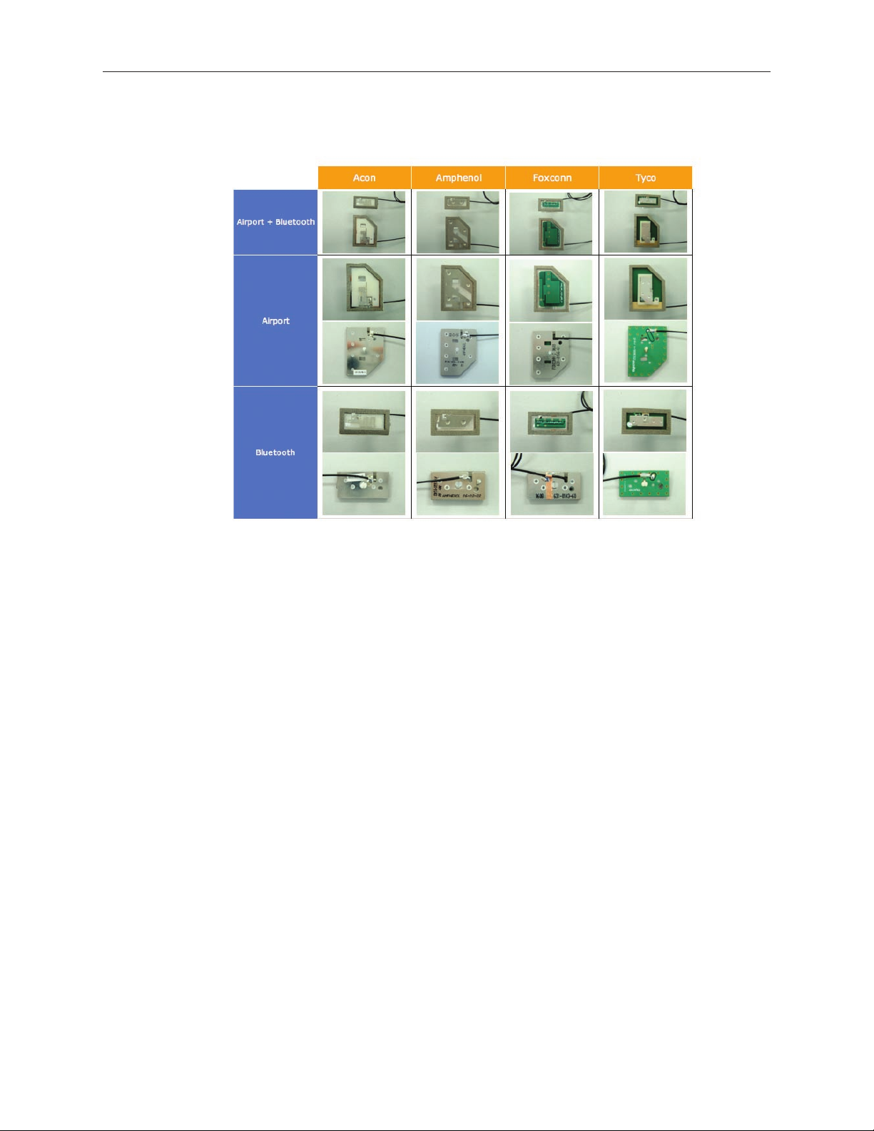
• AirPort Extreme and Bluetooth Antennas
There are four vendors for the antennas (see chart on the next page). If you replace the AirPort antenna, you must replace the Bluetooth antenna at the same time and vice versa. The AirPort and Bluetooth antennas MUST be installed by pairing
under the same manufacturer (for example: Tyco’s Airport antenna with Tyco’s Bluetooth
antenna). Do not mix dierent vendors’ antennas or they may interfere with each other.
Order 922-7602 which contains a paired AirPort and Bluetooth antenna.
Mac mini (Early/Late 2006) and Mac mini (Mid 2007) Take Apart — General Information 7
Page 8
Audio Board is new in this model. It slides into the I/O port and has a exible cable attached •
to it. The audio board connects to the interconnect board.
Interconnect board has been revised. It’s the board that connects to the optical drive and the •
hard drive. The ex cable from the audio board, and the Bluetooth, speaker, IR, and fan cables
connect to this board.
Speaker Shield is new (it sits in front of the speaker and covers the lower speaker screws)•
AirPort Card is dierent from the previous model•
Bluetooth board is new (it’s a tiny board located next to AirPort antenna board)•
Hard drive sensor cable (it connects to the logic board near the battery and it routes under •
fan down to the hard drive)
Memory are SO-DIMMs, 667 MHz DDR2 SDRAM, (see Kbase article 303378)•
IR board is new. It’s on the front side, above the LED •
Thermal Pad is in a dierent location on bottom housing•
SMC Reset button is now located on the logic board, on the AirPort antenna side, near the •
LED connector
Mac mini (Early/Late 2006) and Mac mini (Mid 2007) Take Apart — General Information 8
Page 9
Tools
The following tools are required to service the computer:
ESD wriststrap and mat•
Tweezers•
Jeweler’s #0 Phillips screwdriver•
Jeweler’s #1 Phillips screwdriver•
Phillips #2 screwdriver•
Black stick (922-5065), or other nonconductive nylon or plastic tool•
Needlenose pliers•
Soft cloth (to protect removed parts from scratches)•
Screw tray•
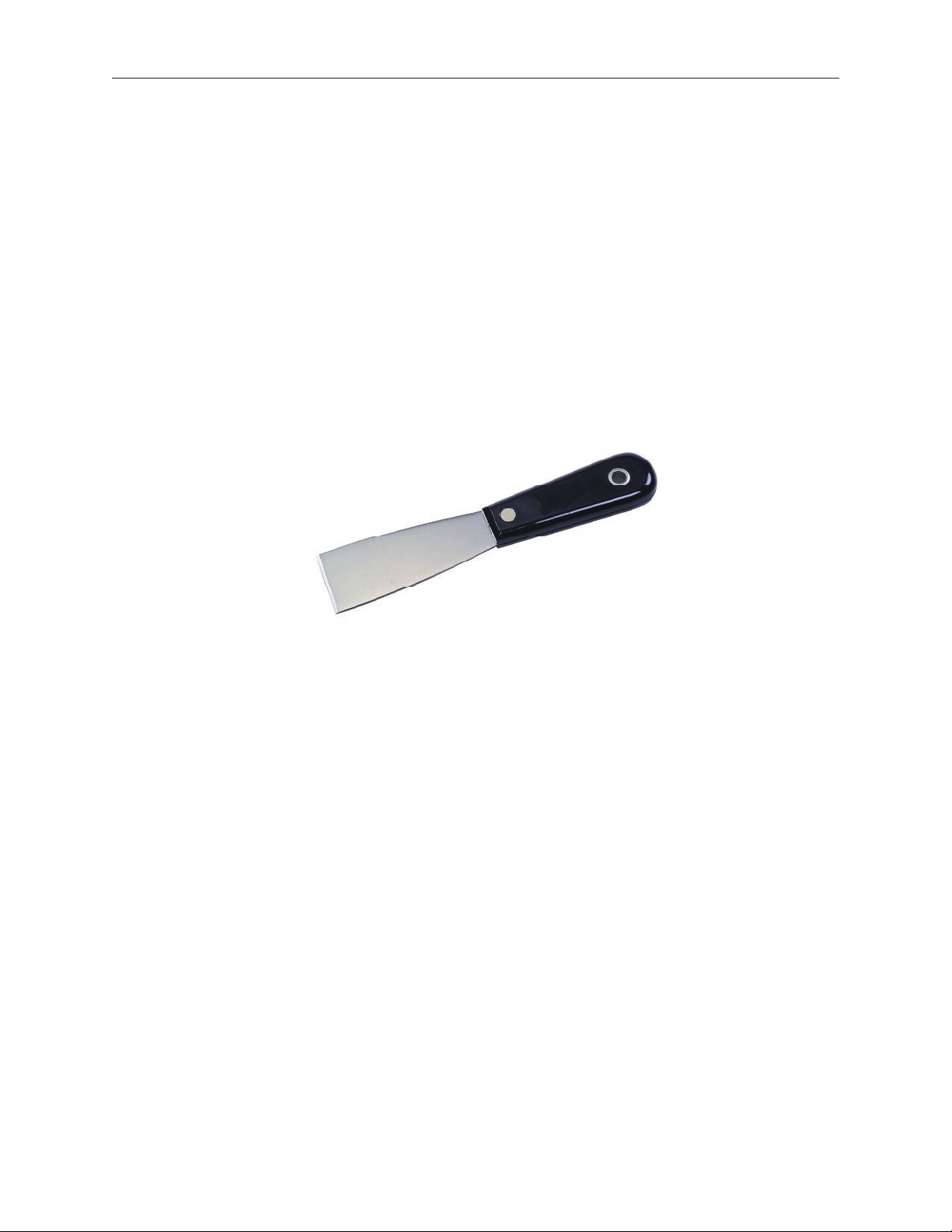
Putty knife (922-6761),1.5 inch (38 mm), exible blade•
Mac mini (Early/Late 2006) and Mac mini (Mid 2007) Take Apart — General Information 9
Page 10
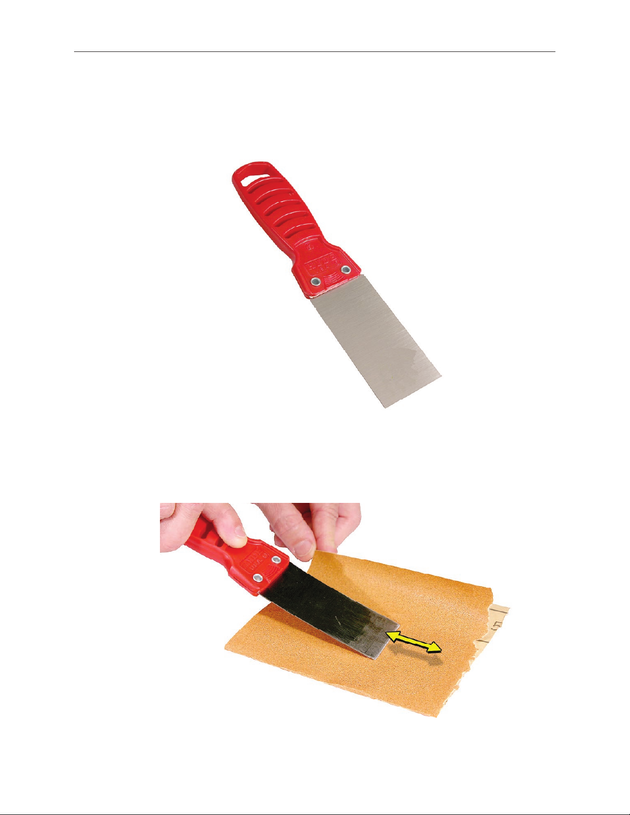
Modify the Putty Knife
If you don’t order a modied putty knife (922-6761) from Apple Service, purchase a putty 1.
knife with a 1.5-inch (38 mm), exible metal blade.
Using sandpaper (150 grit), le down the end of the putty knife (on one side) until it’s slightly 2.
beveled. Rub the edge of the putty knife back and forth for about 2 minutes on the
sandpaper.
Mac mini (Early/Late 2006) and Mac mini (Mid 2007) Take Apart — General Information 10
Page 11
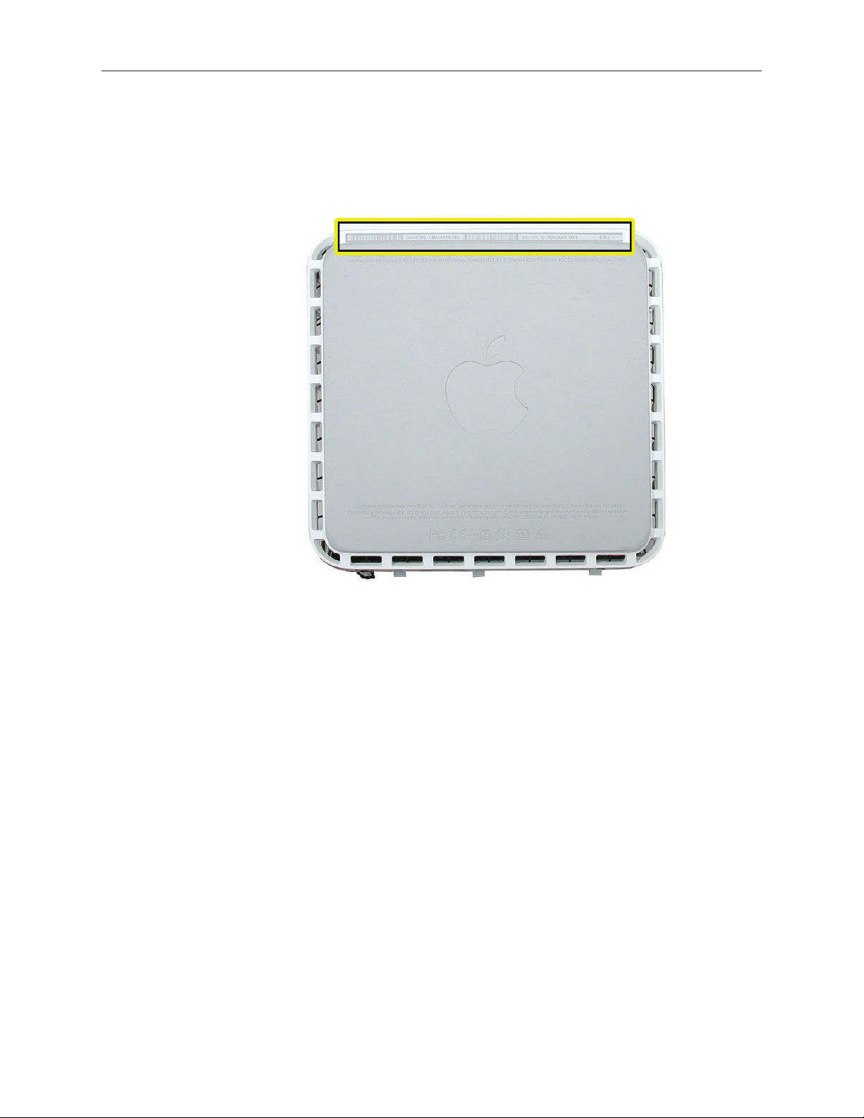
Mac mini Serial Number Location
The product serial number and Ethernet ID are located on the bottom housing.
Mac mini (Early/Late 2006) and Mac mini (Mid 2007) Take Apart — General Information 11
Page 12
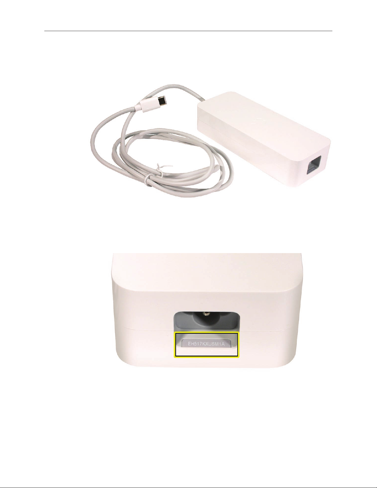
Power Supply Serial Number Location
Locate the power supply. 1.
Look closely into the opening on the end of the power supply. The serial number is located 2.
on
Mac mini (Early/Late 2006) and Mac mini (Mid 2007) Take Apart — General Information 12
Page 13
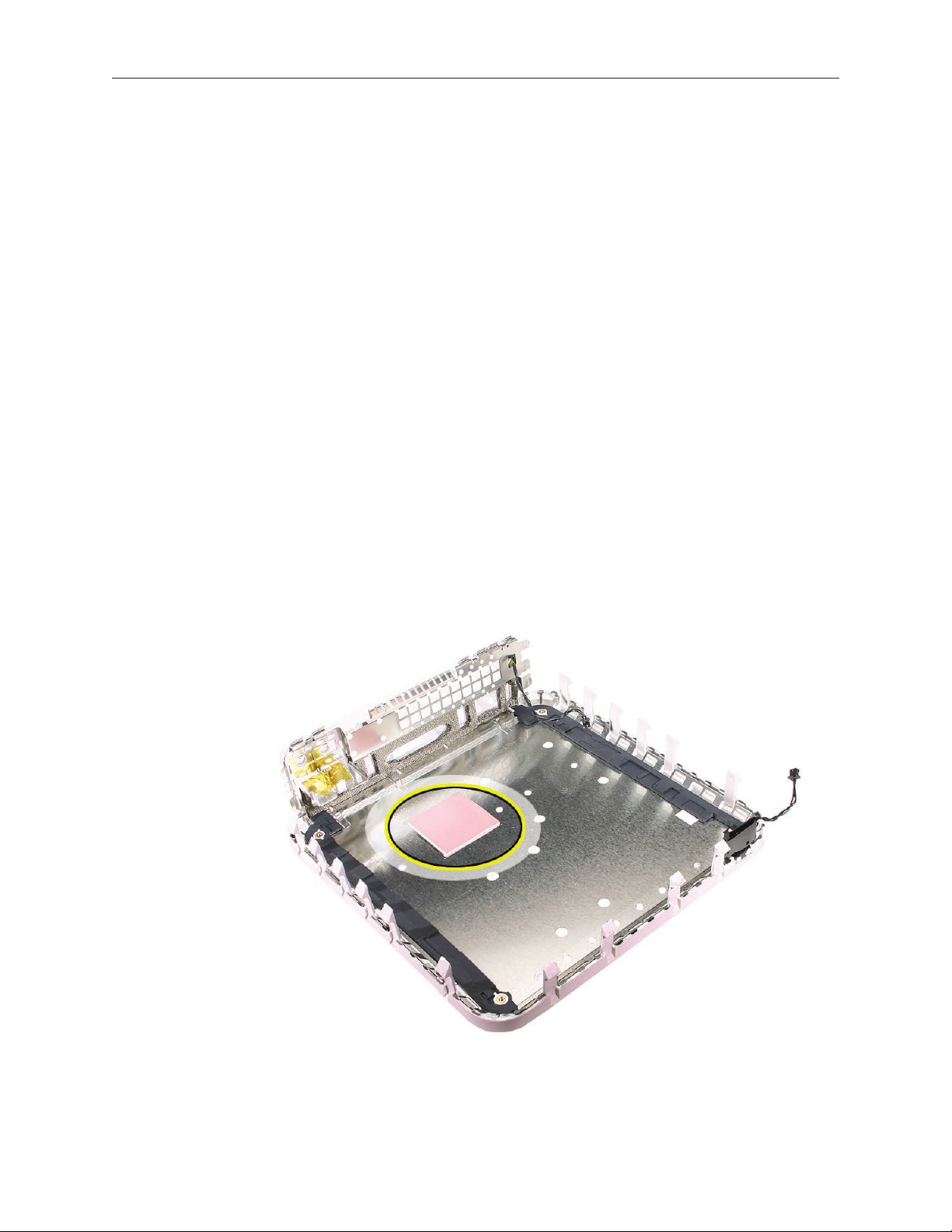
Thermal Pad
The thermal pad is located on the bottom housing. A new thermal pad is included with the logic
board and the bottom housing, and the pads can be ordered separately as a kit (part number
922-6749).
Replace the pad when:
The logic board or the bottom housing is replaced•
The pad is torn, withered, or damaged•
Important: Never use thermal paste in place of the thermal pad. You must replace the thermal
pad with a new identical pad.
Procedure
Remove the original pad from the bottom housing or the logic board using a black stick or 1.
other nonconductive nylon tool.
2. Note: Avoid unnecessary
Remove the protective backing on the new thermal pad.
contact with either side of the thermal pad as dirt and body oils reduce the thermal pad’s
conductivity.
3.
Place the new thermal pad on the bottom housing (as shown). Make sure the thermal pad
has even contact with the bottom housing. There should be no air pockets.
Replace the logic board.4.
Mac mini (Early/Late 2006) and Mac mini (Mid 2007) Take Apart — General Information 13
Page 14
Top Housing
Tools
The only tool required for this procedure is a modied putty knife (part number 922-6761)
Part Location
Mac mini (Early/Late 2006) Take Apart — Top Housing 14
Page 15

Preliminary Steps
Shut down the computer. 1.
Warning: Always shut down the computer before opening it to avoid damaging its internal
components or the components you are installing. Do not open the computer or attempt to
install items inside it while it is on.
2.
Unplug all external cables from the computer except the power cord.
Touch the metal case to discharge any static electricity from your body. 3.
Important: Always discharge static before you touch any parts or install any components
inside the computer. To avoid generating static electricity, do not walk around the room until
you have nished working and closed the computer.
4.
Unplug the power cord.
Put on an ESD wrist strap.5.
Mac mini (Early/Late 2006) Take Apart — Top Housing 15
Page 16
Removal Procedure
Note: The following procedure demonstrates the case-opening on the previous Mac mini
model. The top housing removal procedure is the same for the Mac mini (Early 2006)
computer.
1.
Place the computer on a clean, at surface.
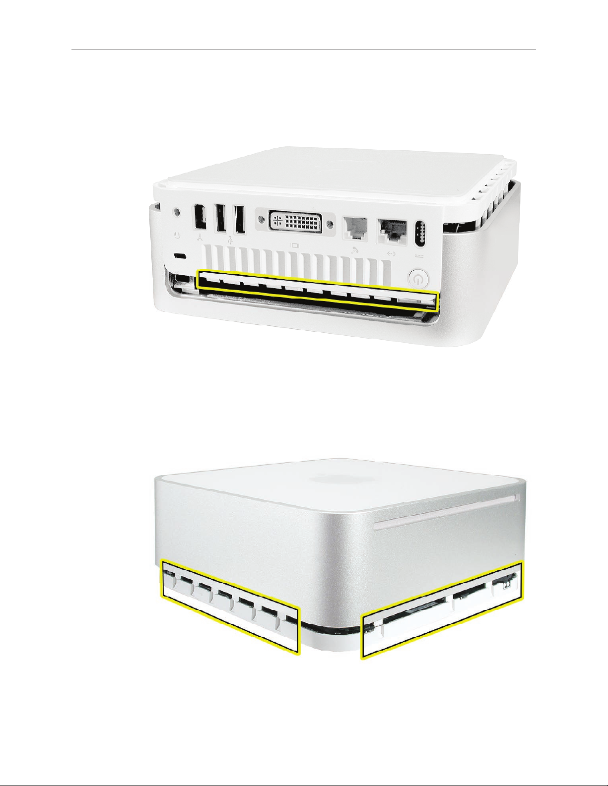
Turn the computer over so the ports are facing you and the bottom of the computer (gray 2.
color) is facing up.
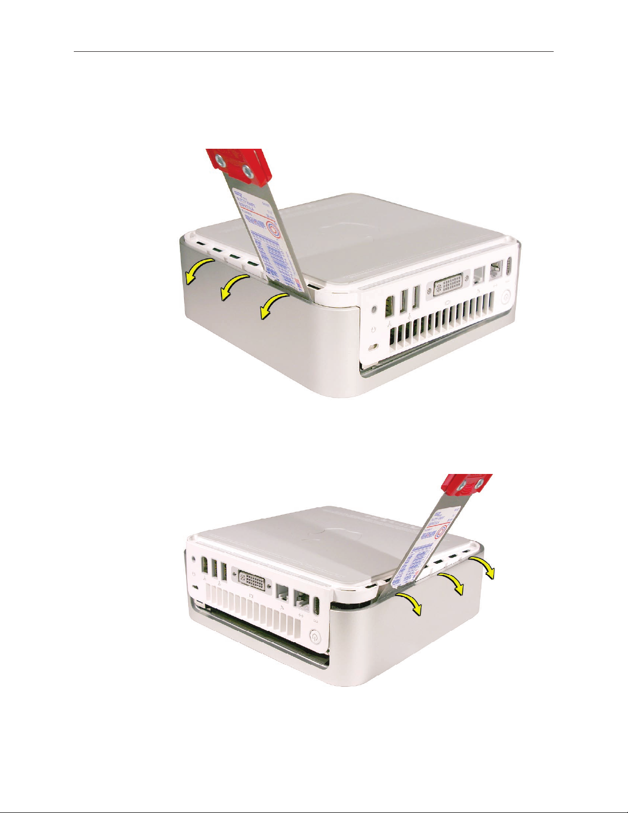
3. : To avoid scratching the case, use caution when using the putty knife. Hold the putty
Note
knife with the beveled edge facing the bottom housing. Insert the tool (0.25 inch / 6.35
millimeters) into the gap where the metal housing and the bottom assembly come together on
the left side of the computer. Be extremely careful not to scratch or dent the top or bottom
housing when inserting the tool.
.
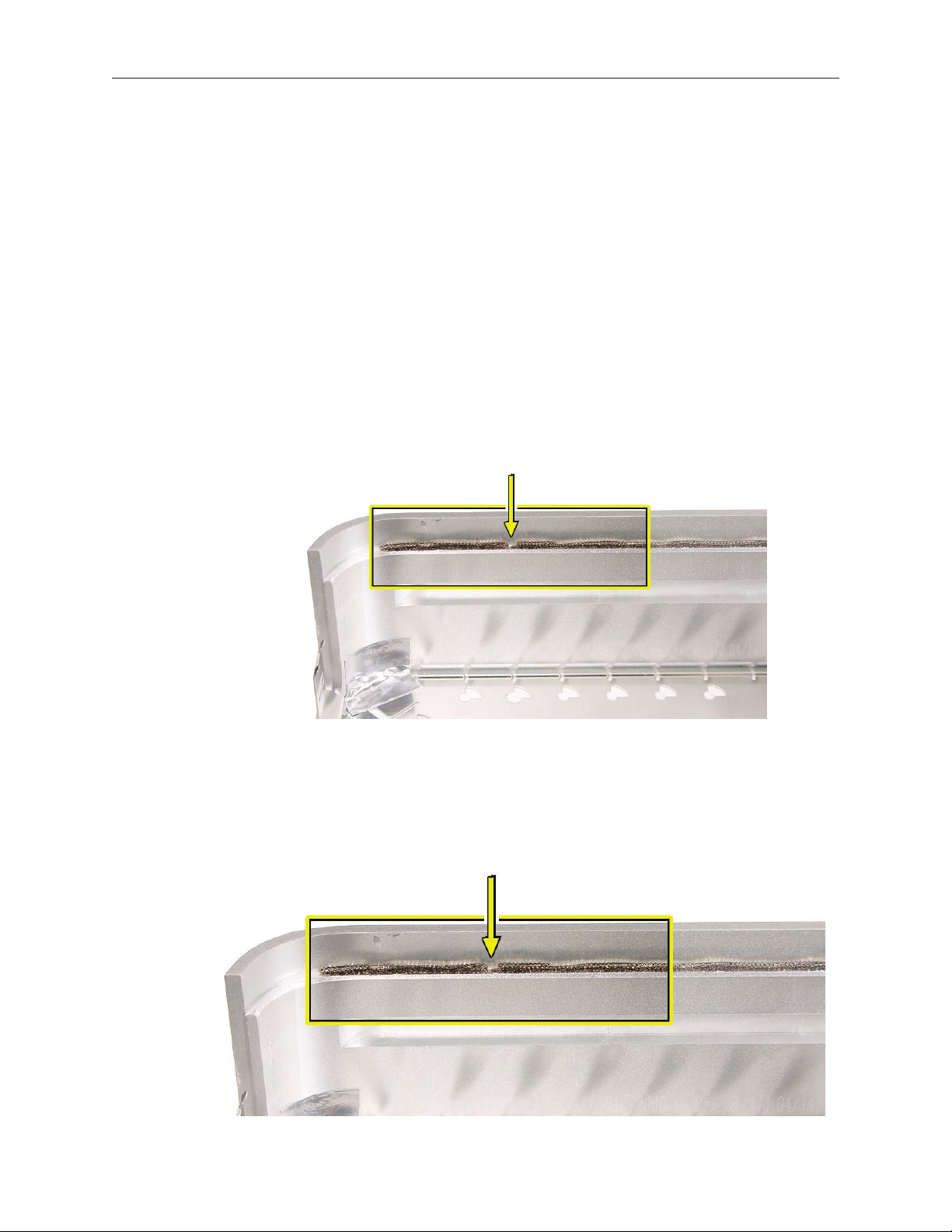
Important: If the tool is inserted too deep it could damage the EMI foam on the inside of the
top housing.
Mac mini (Early/Late 2006) Take Apart — Top Housing 16
Page 17
4.
Gently release the internal latches by prying the tool away from the computer.
Note: You will hear little popping sounds as the latches release and the bottom separates from
the top housing, creating a gap at the top of the I/O panel.
Repeat the procedure on the right side of the computer. 5.
Mac mini (Early/Late 2006) Take Apart — Top Housing 17
Page 18
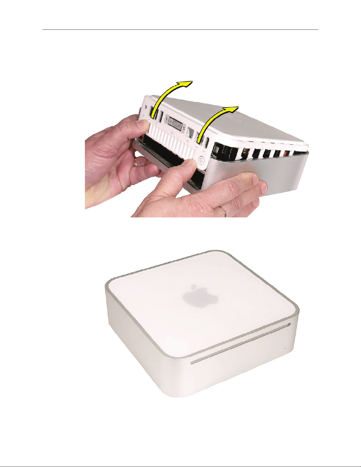
6.
Push the I/O panel upward until the top housing is removed. The popping sounds will
continue as you push the I/O panel; this is normal.
Set the top housing aside. 7.
Mac mini (Early/Late 2006) Take Apart — Top Housing 18
Page 19
Replacement Procedure
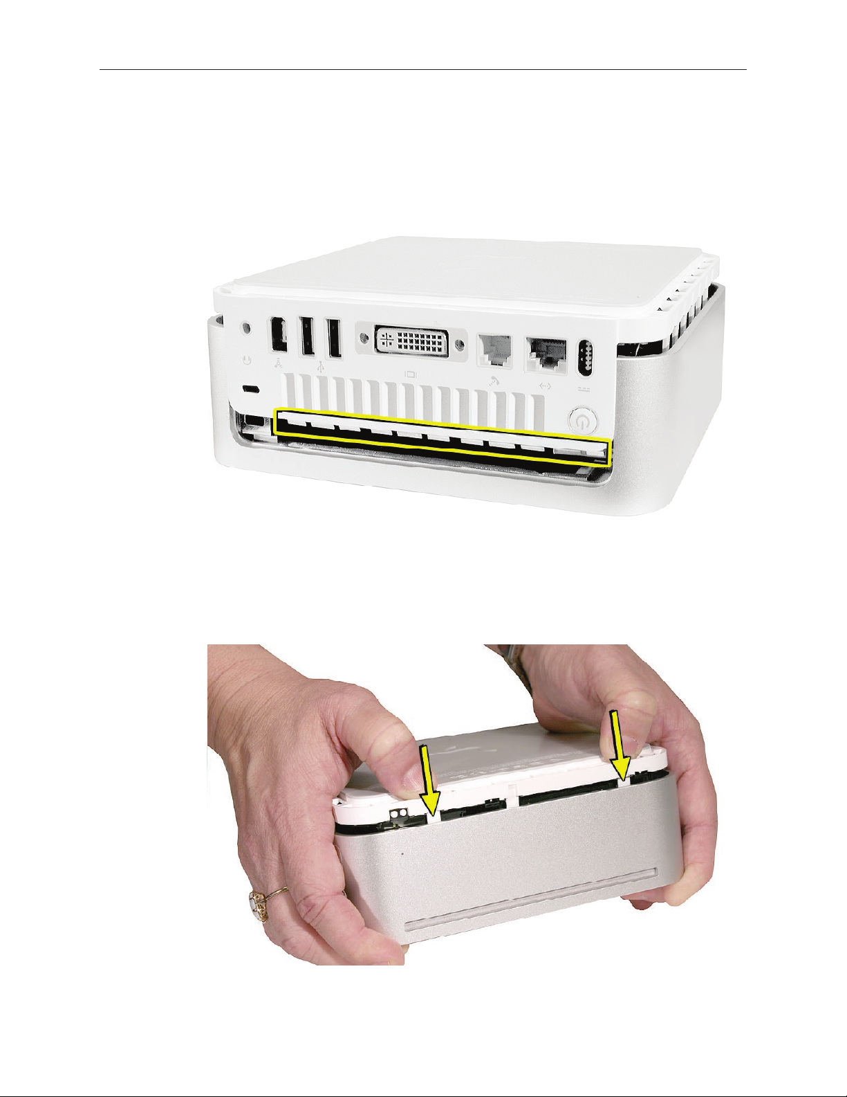
Align the rear I/O panel with the top housing. Make sure all the white latches on the sides of 1.
the unit are aligned as shown in the photo below.
Squeeze the unit together as shown. You will hear popping and cracking noises as you 2.
squeeze the unit together. Proceed to the next step.
Mac mini (Early/Late 2006) Take Apart — Top Housing 19
Page 20
3.
If the computer doesn’t go together, check the EMI tab alignment (outlined below) and try
again. Check that the metal EMI tabs aren’t bent.
Work your hands around the unit squeezing the top and bottom until they snap together and 4.
there are no visible gaps.
Mac mini (Early/Late 2006) Take Apart — Top Housing 20
Page 21
AirPort Antenna
Tools
Phillips #0 screwdriver•
Preliminary Steps
Before you begin, remove
T• op housing
I• nternal frame
Important: If you replace the AirPort antenna, you must replace the Bluetooth antenna at the
same time and vice versa. The AirPort and Bluetooth antennas MUST be installed by pairing
under the same manufacturer (for example: Tyco’s Airport antenna with Tyco’s Bluetooth
antenna). Do not mix dierent vendors’ antennas or they may interfere with each other. Order
922-7602 which contains a paired AirPort and Bluetooth antenna.
Part Location
Mac mini (Early/Late 2006) Take Apart —AirPort Antenna 21
Page 22
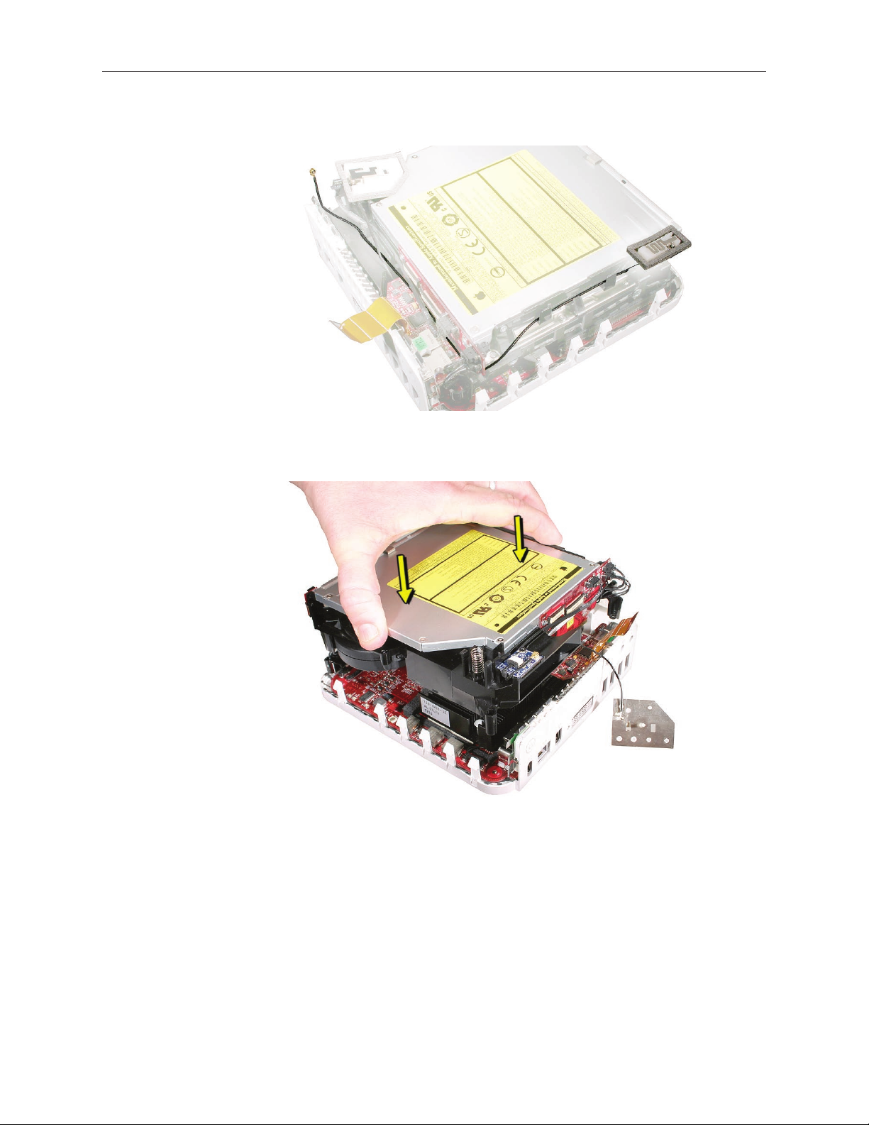
Removal Procedure
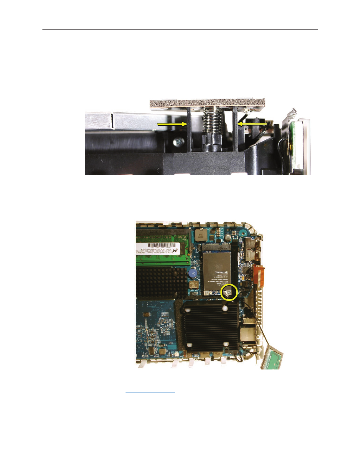
On the internal frame, locate the spring and black plastic posts that the AirPort antenna is 1.
attached to. With your ngers, squeeze the black posts to release the AirPort antenna.
With the internal frame removed, the AirPort Extreme card is visible on the logic board. 2.
Disconnect the AirPort antenna cable from the connector on the AirPort Extreme card. Note:
do not to bend the antenna cable.
Remove the 3. Bluetooth antenna. Important: Replace both the AirPort antenna and
Bluetooth antennas at the same time. Do not mix with dierent vendors’ antennas or they
may interfere with each other
Mac mini (Early/Late 2006) Take Apart —AirPort Antenna 22
Page 23
Replacement Procedure
Replacement Note1. : If you have a failed AirPort antenna, you must replace the Bluetooth
antenna at the same time. The AirPort and Bluetooth antennas MUST be installed by
pairing under the same manufacturer (for example: Tyco’s Airport antenna with Tyco’s
Bluetooth antenna). Do not mix with dierent vendors’ antennas or they may interfere with
each other.
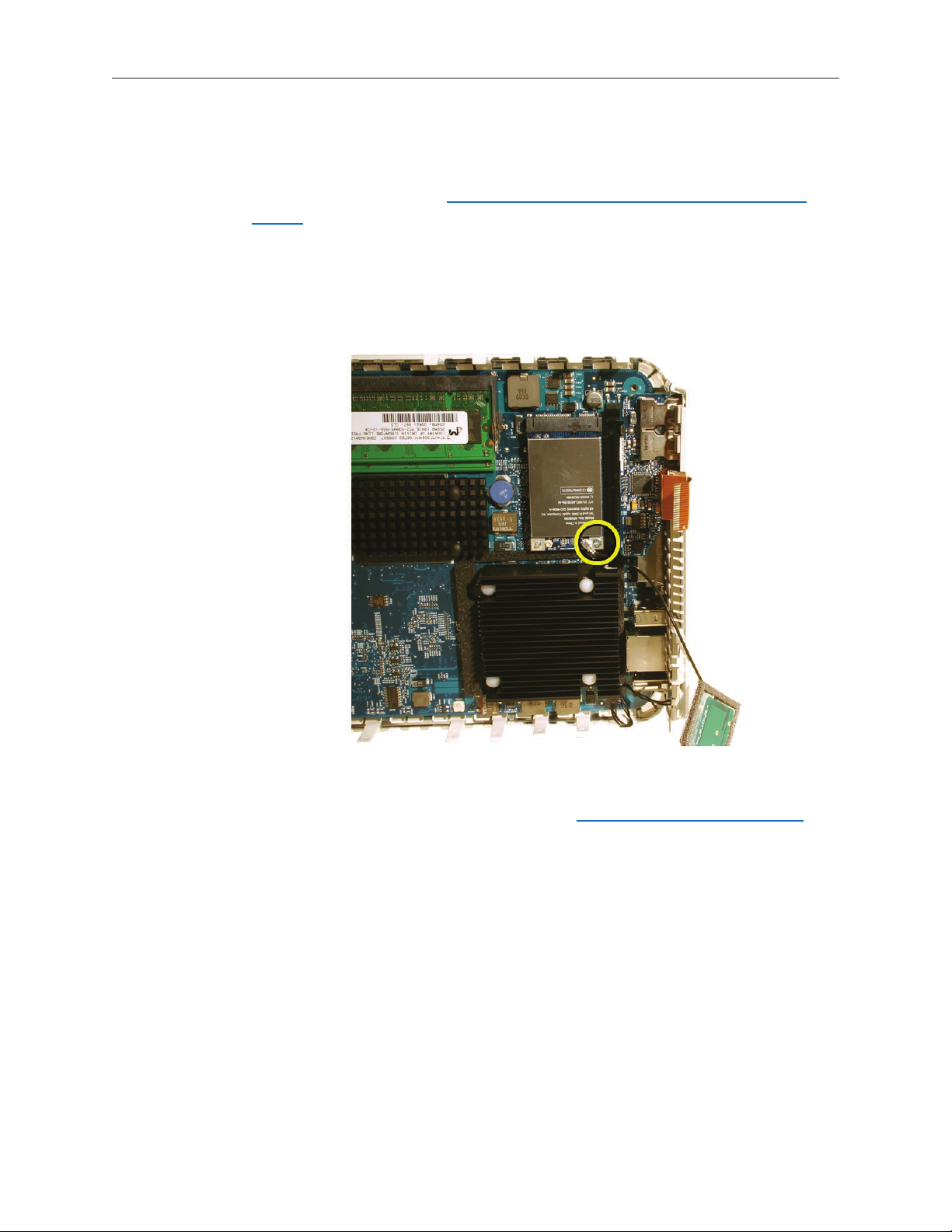
2.
Securely connect the AirPort Extreme antenna to the AirPort Extreme card. Position the
antenna as shown to keep it free of the internal frame.
Replace the Bluetooth antenna (make sure it’s manufactured by the same vendor as the 3.
AirPort antenna) on the internal frame. Refer to the Bluetooth replacement procedure.
Mac mini (Early/Late 2006) Take Apart —AirPort Antenna 23
Page 24
Lower the internal frame onto the bottom housing.4.
5.
Mac mini (Early/Late 2006) Take Apart —AirPort Antenna 24
Page 25
6.
Check the location of the AirPort antenna cable again. Position the antenna as shown on the
internal frame.
Squeeze the black posts as you attach the AirPort antenna to the posts on the internal frame. 7.
Mac mini (Early/Late 2006) Take Apart —AirPort Antenna 25
Page 26
922-7325
922-7324
8. ce the four screws on the internal frame; one screw in each corner, with the longer
Repla
screw (922-7324) attaching in the bottom left corner, near the LED cable.
Replace the9. top housing.
Mac mini (Early/Late 2006) Take Apart —AirPort Antenna 26
Page 27
Internal Frame
Tools
Tools required for this procedure:
Phillips #0 screwdriver•
Tweezers•
Preliminary Steps
Before you begin, remove the top housing and disconnect the AirPort antenna.
Part Location
Mac mini (Early/Late 2006) Take Apart — Internal Frame 27
Page 28
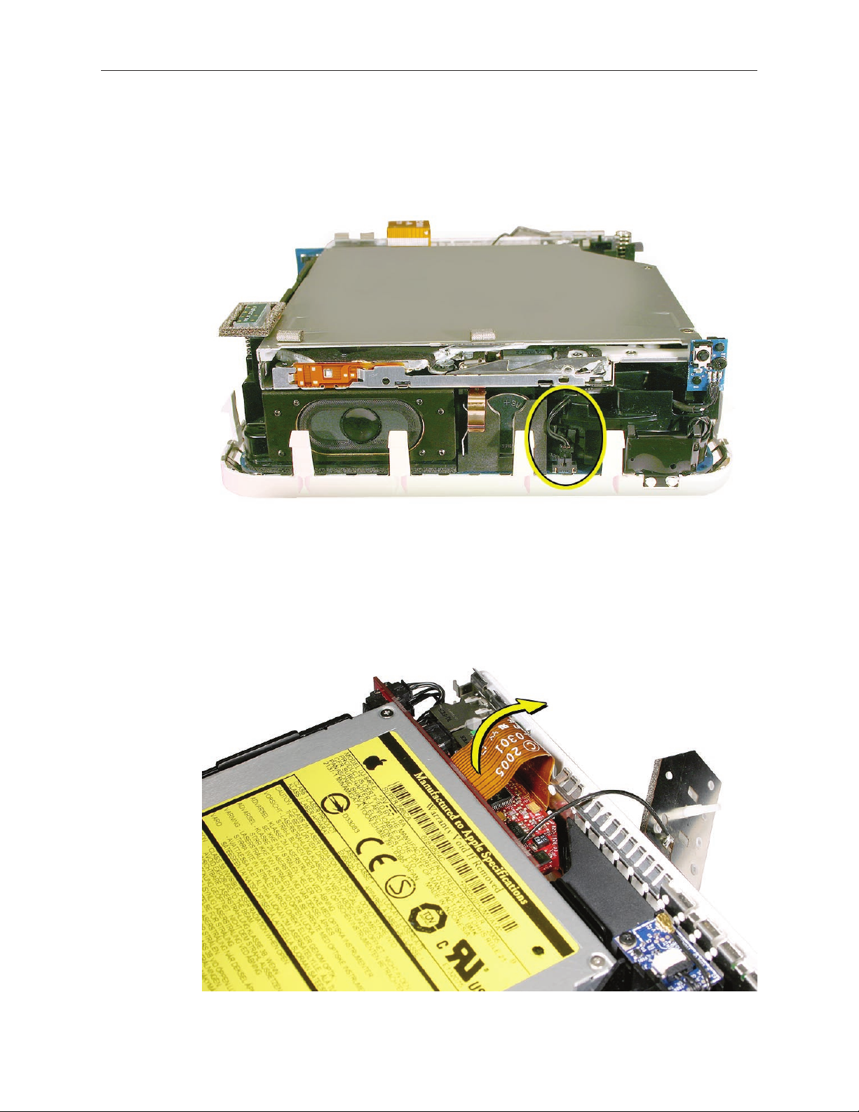
Removal Procedure
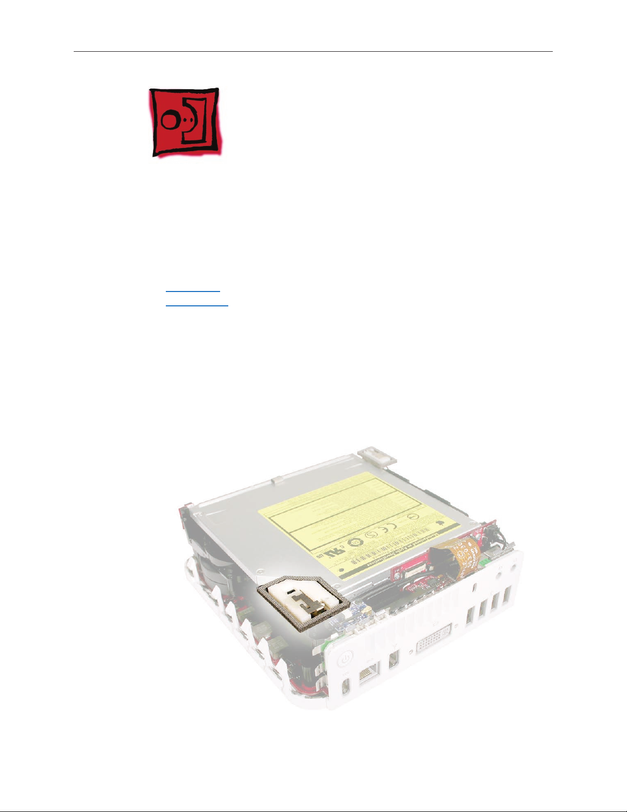
Turn the Mac mini so the front of the computer is facing you (the speaker is facing you). With 1.
a tweezers, disconnect the hard drive sensor cable from the logic board.
Near the I/O ports, disconnect the exible cable on the audio board from the connector on the 2.
interconnect board
Mac mini (Early/Late 2006) Take Apart — Internal Frame 28
Page 29
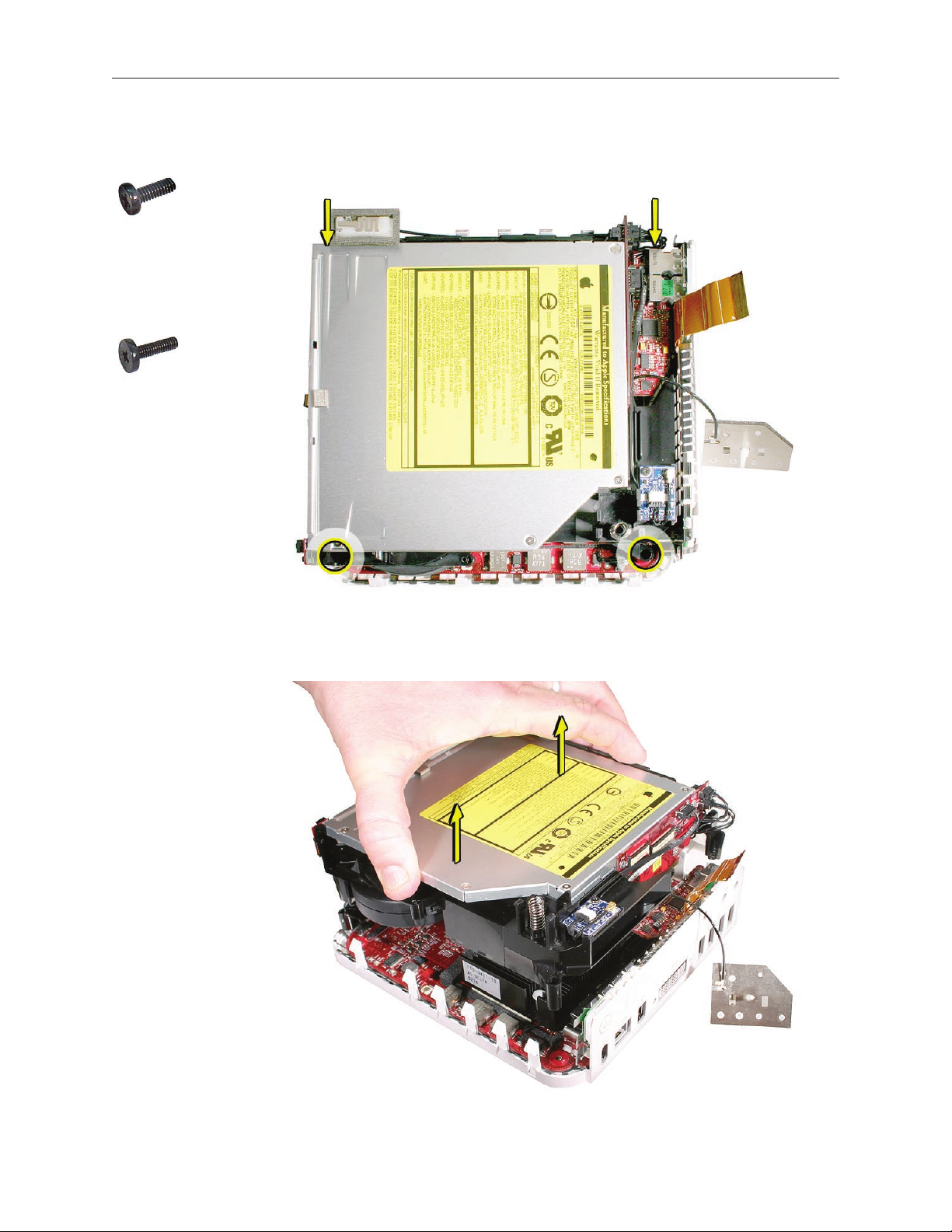
922-7325
922-7324
3. With a jeweler’s Phillips # 0 screwdriver remove four screws on the internal frame; one screw
in each corner of the internal frame. The bottom left screw is longer.
Lift the internal frame straight up and off the bottom housing. 4.
Mac mini (Early/Late 2006) Take Apart — Internal Frame 29
Page 30

5.
The following parts are connected to the internal frame (black plastic frame):
Bluetooth antenna•
Bluetooth board•
Hard drive•
Optical drive•
Fan•
Speaker•
Interconnect board•
IR board•
Hard drive sensor cable•
Refer to the individual take-apart procedures to remove or replace any of these parts.
Mac mini (Early/Late 2006) Take Apart — Internal Frame 30
Page 31

Replacement Procedure
If you removed any service parts from the internal frame, replace them.1.
Check that the Bluetooth board cable and Bluetooth antenna are routed into the two cable 2.
channels (on the left) on the internal frame. Note the routing of the Bluetooth antenna cable
(the thinner cable). It routes under the two connectors (on the right), tucks under the bottom
right corner of the interconnect board and routes along the side of the internal frame, and is
held in place by two tabs.
Lower the internal frame/drive module sub assembly onto the bottom housing. Align the gold 3.
ngers of the interconnect board with the matching connector on the logic board .
Mac mini (Early/Late 2006) Take Apart — Internal Frame 31
Page 32

4.
Route the AirPort antenna cable up through the opening in the internal frame.
Check that the power button cable is not pinched by the internal frame. 5.
Mac mini (Early/Late 2006) Take Apart — Internal Frame 32
Page 33

922-7325
922-7324
6. Replace the four screws on the internal frame securing the longer screw (922-7324) in the
bottom left corner, near the LED cable.
Connect the exible cable on the audio board to the interconnect board. 7.
Mac mini (Early/Late 2006) Take Apart — Internal Frame 33
Page 34

8.
Replace the AirPort Extreme antenna onto the spring/post. Make sure it’s securely connected.
Replace the 9. top housing.
Mac mini (Early/Late 2006) Take Apart — Internal Frame 34
Page 35

Bluetooth Antenna
Tools
Phillips #0 screwdriver is required for this procedure.•
Black stick (or other nonconductive nylon or plastic tool)•
Preliminary Steps
Before you begin, remove
T• op housing
Disconnect the AirPort antenn• a
Important: If you replace the Bluetooth antenna, you must replace the AirPort antenna at the
same time and vice versa. The AirPort and Bluetooth antennas MUST be installed by pairing
under the same manufacturer (for example: Tyco’s Airport antenna with Tyco’s Bluetooth
antenna). Do not mix dierent vendors’ antennas or they may interfere with each other. Order
922-7602 which contains a paired AirPort and Bluetooth antenna.
Part Location
Mac mini (Early/Late 2006) Take Apart — Bluetooth Antenna 35
Page 36

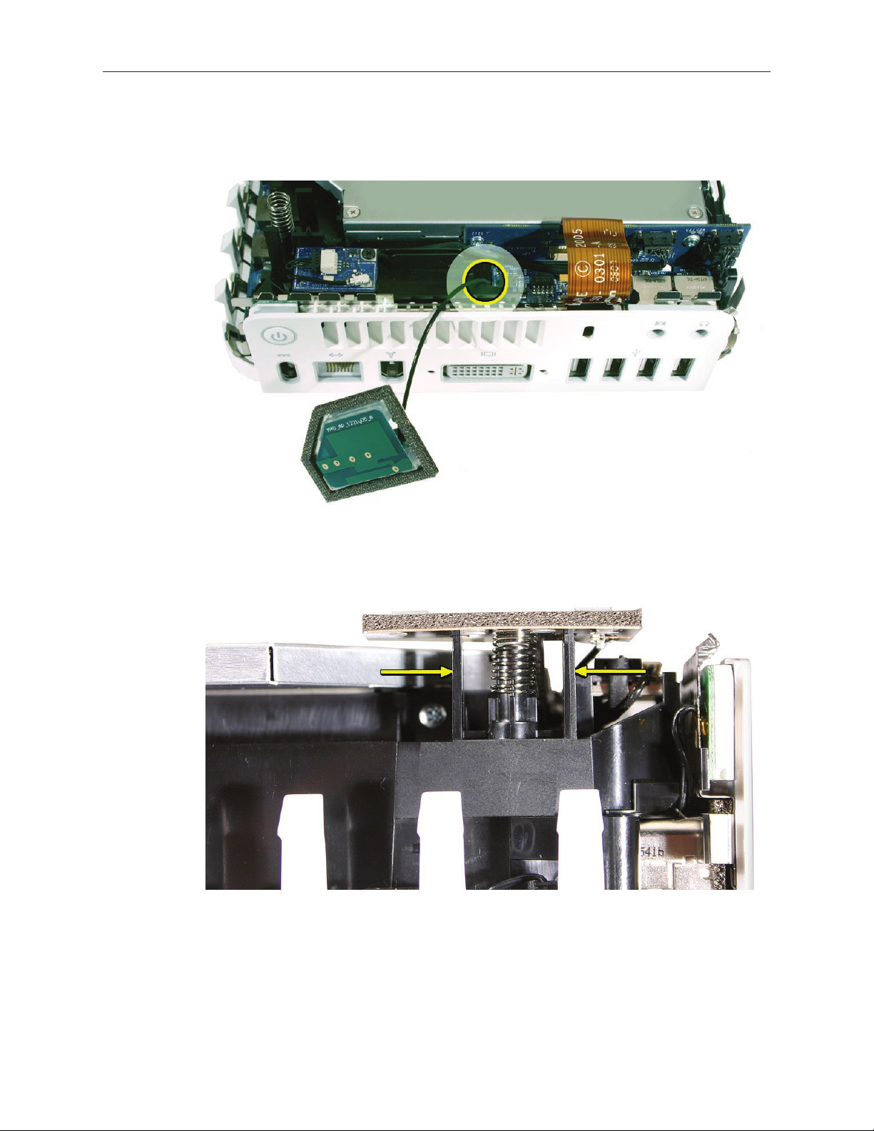
Removal Procedures
Disconnect the exible cable going from the audio board to the interconnect board. 1.
Disconnect the Bluetooth antenna from the Bluetooth board. 2.
Mac mini (Early/Late 2006) Take Apart — Bluetooth Antenna 36
Page 37

Grab the Bluetooth antenna board shield (shown on the right) by its edges and give a rm 3.
tug upward. Release the rest of the antenna cable from the side tabs and pull the antenna
free. Important: Take care handling the Bluetooth antenna as a bent or warped antenna will
aect Bluetooth connectivity.
Remove and replace the 4. AirPort antenna. Important: Replace both the AirPort and
Bluetooth antennas if one or the other antennas fail. The antennas must be paired with the
same vendor. If you mix vendors the antennas may interfere with each other.
Mac mini (Early/Late 2006) Take Apart — Bluetooth Antenna 37
Page 38

Replacement Procedure
Mount the Bluetooth antenna shield on the internal frame. Gently press the antenna shield a 1.
few times to make sure the spring is spongy .
Route the antenna along the side of the internal frame, tucking the antenna into the black 2.
tabs. Route the Bluetooth antenna around the bottom edge of the interconnect board .
Mac mini (Early/Late 2006) Take Apart — Bluetooth Antenna 38
Page 39

3.
Continue routing the Bluetooth antenna cable (thinner cable) along the front of the
interconnect board and into the “outside” cable slot (visible on the left side of the picture).
Note: The Bluetooth board -to-interconnect board-cable (thicker cable) routes into the
“inside” cable slot, (or behind the Bluetooth antenna cable) on the internal frame.
)
Route the Bluetooth antenna around the underside of the Bluetooth board. Connect the 4.
antenna to the board.
.
Mac mini (Early/Late 2006) Take Apart — Bluetooth Antenna 39
Page 40

5.
Connect the exible cable to the interconnect board.
Replace the AirPort antenna. 6. Note: Make sure the AirPort and Bluetooth are the same vendor
manufacturer.
7.
Replace the top housing.
Mac mini (Early/Late 2006) Take Apart — Bluetooth Antenna 40
Page 41

Bluetooth Board
Tools
Black stick (or other nonconductive nylon or plastic tool)•
Jeweler’s Phillips #0 screwdriver•
Preliminary Steps
Before you begin, remove
T• op housing
AirPort antenn• a
Part Location
Mac mini (Early/Late 2006) Take Apart — Bluetooth Board 41
Page 42

Removal Procedure
Disconnect the Bluetooth antenna (circled) from the Bluetooth board. 1.
922-7322
R2. emove the one Phillip’s screw and disconnect the Bluetooth cable from the Bluetooth
board. Lift the board o the internal frame. Important: Take care handling the Bluetooth
antenna as a bent or warped antenna will aect Bluetooth connectivity.
Mac mini (Early/Late 2006) Take Apart — Bluetooth Board 42
Page 43

Replacement Procedure
1.
Route the Bluetooth cable (thicker cable) into the inside cable channel and the Bluetooth
antenna into the outside cable channel.
922-7322
2. Position the Bluetooth board on the internal frame. Note: The board tucks under a tiny lip
(on the frame) near the top left corner of the board. Position the cables so they go under and
around the edge of the board. Connect the Bluetooth cable, the antenna, and replace the
screw on the Bluetooth board.
.
Mac mini (Early/Late 2006) Take Apart — Bluetooth Board 43
Page 44

3.
Attach the AirPort antenna /shield to the posts on the internal frame.
Replace the top housing.4.
Mac mini (Early/Late 2006) Take Apart — Bluetooth Board 44
Page 45

Memory
Tools
The only tool required for this procedure is a Jeweler’s Phillips #0 screwdriver.
Preliminary Steps
Before you begin, remove
Top housin• g
Disconnect the AirPort antenn• a
Internal frame•
Part Location
Mac mini (Early/Late 2006) Take Apart — Memory 45
Page 46

Removal Procedure
Press the metal latches outward to release the memory DIMMs.. 1.
The DIMM will pop up slightly. Pull the DIMM from the slot on the logic board. 2.
Mac mini (Early/Late 2006) Take Apart — Memory 46
Page 47

Replacement Procedure
Install the DIMM module into the slot on the logic board. 1.
Line up the notch on the DIMM with the notch on the slot. 2. Important: Press the DIMM into
the slot until it clicks into place.
Press down on the sides and center of the DIMM so the metal latches grab the DIMM .3.
Lower the internal frame/drive module sub assembly onto the bottom housing. Align the gold 4.
ngers of the interconnect board with the matching connector on the logic board.
Mac mini (Early/Late 2006) Take Apart — Memory 47
Page 48

5.
Route the AirPort antenna cable up through the opening in the internal frame.
Check that the power button cable is not pinched by the internal frame. 6.
Mac mini (Early/Late 2006) Take Apart — Memory 48
Page 49

922-7325
922-7324
7. Replace the four screws on the internal frame.
Connect the exible cable on the audio board to the interconnect board. 8.
Mac mini (Early/Late 2006) Take Apart — Memory 49
Page 50

9.
Replace the AirPort Extreme antenna onto the spring/post. Make sure it’s securely connected.
Replace the 10. top housing.
Mac mini (Early/Late 2006) Take Apart — Memory 50
Page 51

Audio Board
Tools
Jeweler’s Phillips #0 screwdriver•
Preliminary Steps
Before you begin, remove
T• op housing
AirPort antenna•
Part Location
Mac mini (Early/Late 2006) Take Apart — Audio Board 51
Page 52

Removal Procedure
Disconnect the exible cable from the interconnect board. 1.
922-6680
Remove the 2. internal frame to avoid damaging components on the audio board.
3. Place your nger under the audio board to support the board as you remove the screw. The
audio board should lift out of the ports without much resistance.
Mac mini (Early/Late 2006) Take Apart — Audio Board 52
Page 53

4.
Rotate the front of the board up from the tab, then pull the board up and out, keeping clear
of the mounting stando.
Mac mini (Early/Late 2006) Take Apart — Audio Board 53
Page 54

Replacement Procedure
Be sure that audio connectors are properly aligned and seated completely within the 1.
rectangular recesses of the audio frame. Ensure that they are fully seated. When they are
seated, the board should rotate down into position on the stando without resistance.
922-6680
,
2. Replace the audio board screw. Important: Support the underside of the audio board with
your nger as you tighten the audio screw.
I
Mac mini (Early/Late 2006) Take Apart — Audio Board 54
Page 55

922-7325
922-7324
3.
Replace the internal frame onto the bottom housing.
4. Replace the four screws that secure the internal frame to the bottom housing. The longer
screw attaches to the bottom left corner, near the LED.
Connect the exible cable to the interconnect board.5.
Connect the AirPort antenna to the internal frame.6.
Replace the top housing.7.
Mac mini (Early/Late 2006) Take Apart — Audio Board 55
Page 56

AirPort Extreme Card
Tools
Jeweler’s Phillips #0 screwdriver•
Needlenose pliers•
Preliminary Steps
Before you begin, remove
Top housin• g
Internal frame•
Part Location
Mac mini (Early/Late 2006) Take Apart —AirPort Extreme Card 56
Page 57

Removal Procedure
Disconnect the AirPort antenna cable from the connector on the AirPort Extreme card. 1. Note:
do not to bend the antenna cable.
922-6680
2. With a jeweler’s Phillips #0 screwdriver, remove the screw on the AirPort Extreme card.
Mac mini (Early/Late 2006) Take Apart —AirPort Extreme Card 57
Page 58

3.
The card will pop up when the screw is removed. Pull the card from the slot on the logic
board.
922-7327
4. If you are replacing the AirPort Extreme card, remove the plastic stando and transfer the
stando to the replacement AirPort Extreme card.
Mac mini (Early/Late 2006) Take Apart —AirPort Extreme Card 58
Page 59

Replacement Procedure
Install the AirPort Extreme card into the slot on the logic board. 1.
922-6680
Press the card down and replace the screw. 2.
Mac mini (Early/Late 2006) Take Apart —AirPort Extreme Card 59
Page 60

3.
Attach the AirPort antenna to the AirPort Extreme card..
Lower the internal frame/drive module sub assembly onto the bottom housing. Align the gold 4.
ngers of the interconnect board with the matching connector on the logic board.
Mac mini (Early/Late 2006) Take Apart —AirPort Extreme Card 60
Page 61

5.
Route the AirPort antenna cable up through the opening in the internal frame.
Check that the power button cable is not pinched by the internal frame. 6.
Mac mini (Early/Late 2006) Take Apart —AirPort Extreme Card 61
Page 62

922-7325
922-7324
7. Replace the four screws on the internal frame. Note: The longer screw attaches to the bottom
left corner, near the LED.
Connect the exible cable on the audio board to the interconnect board. 8.
Mac mini (Early/Late 2006) Take Apart —AirPort Extreme Card 62
Page 63

9.
Replace the AirPort Extreme antenna onto the spring/post. Make sure it’s securely connected.
Replace the 10. top housing.
Mac mini (Early/Late 2006) Take Apart —AirPort Extreme Card 63
Page 64

Hard Drive Sensor Cable
Tools
Black stick or other nonconductive tool,•
Preliminary Steps
Before you begin, remove
T• op housing
AirPort antenn• a
Part Location
Mac mini (Early/Late 2006) Take Apart — Optical Drive 64
Page 65

Removal Procedure
Using a tweezers, disconnect the hard drive sensor cable from the logic board. 1.
Remove the 2. internal frame.
3. hard drive.
Remove the
4. optical drive.
Remove the
5.
Free the sensor cable from the cable channel. Pull the hard drive sensor cable out of the
internal frame.
Mac mini (Early/Late 2006) Take Apart — Optical Drive 65
Page 66

Replacement Procedure
Tuck the sensor cable into the internal frame and route the cable into the channel and 1.
around the black pole on the internal frame (near the fan) .
Replace the optical drive. 2.
Replace the hard drive.3.
Check the cable routing again before turning the frame over and attaching the internal 4.
frame to the bottom housing.
Mac mini (Early/Late 2006) Take Apart — Optical Drive 66
Page 67

922-7325
922-7324
5. Replace the four internal frame screws. Note: The longer screw goes into the bottom left
corner, near the LED connector.
Connect the sensor cable to the logic board with a pair of tweezers. 6.
Replace the AirPort antenna and the top housing.7.
Mac mini (Early/Late 2006) Take Apart — Optical Drive 67
Page 68

IR Board and Cable
Tools
Jeweler’s Phillips #0 screwdriver•
Preliminary Steps
Before you begin, remove
Top housin• g
Disconnect the AirPort antenn• a
Disconnect the hard drive sensor from the logic board•
Internal frame•
Part Location
Mac mini (Early/Late 2006) Take Apart — IR Board 68
Page 69

922-7322
Removal Procedure
1. Using a jeweler’s Phillips #0 screwdriver, remove the screw from the IR (infrared) board.
Note the cable routing from the front before you ip the internal frame over (toward you) 2.
and disconnect the cable from the interconnect board.
Mac mini (Early/Late 2006) Take Apart — IR Board 69
Page 70

3.
Remove the IR cable from the cable channel.
Disconnect the IR cable from the lower connector on the interconnect board. 4.
Mac mini (Early/Late 2006) Take Apart — IR Board 70
Page 71

Replacement Procedure
Connect the IR connector to the lower connector on the interconnect board and route the 1.
cable up into the cable channel on the internal frame.
Tuck the cables under the tabs near the interconnect board. Route the cable around the pole 2.
near the fan.
Mac mini (Early/Late 2006) Take Apart — IR Board 71
Page 72

922-7322
3. Flip the internal frame over and route the cable through the internal frame as shown below.
Replace the screw on the IR board.
4. Replace the internal frame onto the bottom housing. Replace the four screws, with the
longer screw attaching to the bottom left corner near the LED.
922-7325
922-7324
With a tweezers, connect the hard drive sensor cable (near the speaker) to the logic board.5.
Connect the Airport antenna to the internal frame.6.
Replace the top housing.7.
Mac mini (Early/Late 2006) Take Apart — IR Board 72
Page 73

Mac mini (Early/Late 2006) Take Apart — IR Board 73
Page 74

Hard Drive
Tools
Phillips #1 screwdriver•
Black stick or other nonconductive tool,•
Preliminary Steps
Before you begin, remove
T• op housing
I• nternal frame
D• isconnect the AirPort antenna
Part Location
Mac mini (Early/Late 2006) Take Apart — Hard Drive 74
Page 75

922-6681
Removal Procedure
1. Flip the internal frame over to see the hard drive. Using a Phillip’s #1 screwdriver, remove the
four hard drive screws.
With a black stick or other nonconductive tool, pry the hard drive o the connector on the 2.
interconnect board. Pull the hard drive in the direction of the speaker.
Mac mini (Early/Late 2006) Take Apart — Hard Drive 75
Page 76

Replacement Procedure
With the circuit-side of the hard drive face up, slide the hard drive into the internal frame and 1.
under the two screw holes circled. Push the drive to the right and line up the hard drive pins
with the interconnect board. Push the hard drive pins into the interconnect board connector.
922-6681
2. Replace the four hard drive screws.
Mac mini (Early/Late 2006) Take Apart — Hard Drive 76
Page 77

Make sure all the cables are tucked under the internal frame as shown. 3.
Flip the internal frame over.4.
Replace the 5. internal frame on the bottom housing. Replace the four internal frame
screws.
6.
Connect the AirPort antenna cable.
Replace the top housing.7.
Mac mini (Early/Late 2006) Take Apart — Hard Drive 77
Page 78

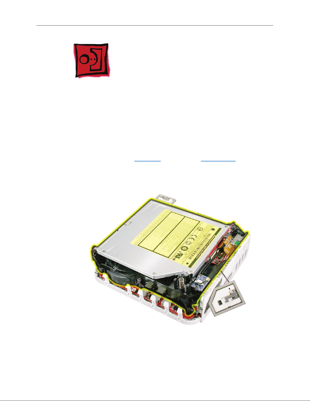
Optical Drive
Tools
Black stick (or other nonconductive nylon or plastic tool)•
Jeweler’s Phillips #0 screwdriver•
Preliminary Steps
Before you begin, remove
T• op housing
Internal fram• e
Part Location
Mac mini (Early/Late 2006) Take Apart — Optical Drive 78
Page 79

922-6680
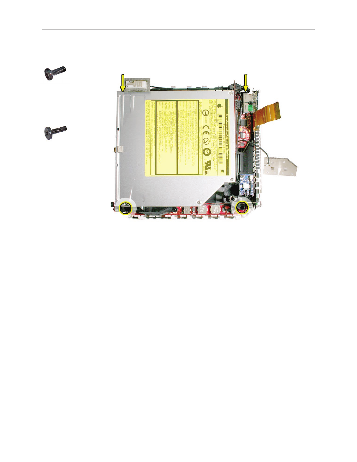
Removal Procedure
1. Using a jeweler’s Phillips #0 screwdriver, remove the two optical drive screws on the side of
the internal frame that has the Bluetooth antenna. Rotate the internal frame 180 degrees.
2. Remove the other two optical drive screws.
922-6680
Mac mini (Early/Late 2006) Take Apart — Optical Drive 79
Page 80

922-6680
3. Using a jeweler’s Phillips #0 screwdriver, remove the two screws on the interconnect board.
Holding the optical drive by the sides, use a black stick to pry the optical drive connector o 4.
the interconnect board. Remove the optical drive from the internal frame.
.
Mac mini (Early/Late 2006) Take Apart — Optical Drive 80
Page 81

Replacement Procedure
Hold the optical drive by its sides. 1. Note: Never squeeze or handle the optical drive by the
front or center; you could damage the optical drive.
2.
Position the optical drive on the internal frame and connect the interconnect board to the
optical drive connector.
922-6680
3. Replace the two interconnect board screws.
Mac mini (Early/Late 2006) Take Apart — Optical Drive 81
Page 82

922-6680
4. Replace the optical drive screws on one side, then rotate the internal frame 180 degrees.
5. Replace the two remaining optical drive screws.
922-6680
Lower internal frame onto the bottom housing. 6. Replace the four internal frame screws.
7.
Reconnect the AirPort antenna (if disconnected) to the black posts on the internal frame.
Replace the top housing. 8.
Mac mini (Early/Late 2006) Take Apart — Optical Drive 82
Page 83

Fan
Tools
The only tool required for this procedure is a jeweler’s Phillips #0 screwdriver.
Preliminary Steps
Before you begin, remove
T• op housing
Disconnect the AirPort antenn• a
I• nternal frame
Part Location
Mac mini (Early/Late 2006) Take Apart — Fan 83
Page 84

922-7323
Removal Procedure
1. Remove the two fan screws with a jeweler’s Phillips #0 screwdriver.
Free the fan from the internal frame (top left corner) and unhook the fan cable. 2.
Mac mini (Early/Late 2006) Take Apart — Fan 84
Page 85

3. Disconnect the fan cable from the connector on the interconnect board. Replacement Note:
If the fan connector is disconnected, the computer will quickly ash the LED and then shut
o.
Lift the fan out of the internal frame.4.
Mac mini (Early/Late 2006) Take Apart — Fan 85
Page 86

Replacement Procedure
Tuck the fan under the internal frame and route the cable into the cable channel. 1.
922-7323
Replace the two fan screws with a jeweler’s Phillips #0 screwdriver. 2.
Mac mini (Early/Late 2006) Take Apart — Fan 86
Page 87

Connect the fan cable to the upper connector on the interconnect board and route the 3.
cable as shown below. Replacement Note: If the fan connector is disconnected, the
computer will quickly ash the LED and then shut o.
Turn over the internal frame.4.
Replace the internal frame5. and four screws.
6. AirPort antenna to the internal frame.
Connect the
7.
Connect the hard drive sensor cable to the logic board.
Replace the 8. top housing.
Mac mini (Early/Late 2006) Take Apart — Fan 87
Page 88

Mac mini (Early/Late 2006) Take Apart — Fan 88
Page 89

Mac mini (Early/Late 2006) Take Apart — Fan 89
Page 90

Interconnect Board
Tools Required
Jeweler’s Phillips #0 screwdriver•
Black stick or nonconductive tool•
Preliminary Steps
Before you begin remove
T• op housing
Disconnect the AirPort antenn• a
I• nternal frame
Part Location
Mac mini (Early/Late 2006) Take Apart — Interconnect Board 90
Page 91

Removal Procedure
Disconnect the four cables (Bluetooth, IR, fan, and speaker) attached to the interconnect 1.
board
922-6680
2. Using a jeweler’s Phillips #0 screwdriver, remove two screws on the interconnect board.
Mac mini (Early/Late 2006) Take Apart — Interconnect Board 91
Page 92

Remove the 3. optical drive screws; two on each side of the internal frame.
4.
With a black stick or other nonconductive tool, pry the interconnect board o the optical
drive connector and hard drive pins.
Mac mini (Early/Late 2006) Take Apart — Interconnect Board 92
Page 93

Replacement Procedure
With the gold pins on the interconnect board facing down, press the interconnect board 1.
onto the hard drive and optical drive connectors.
Connect the IR cable (A), the fan cable (B), and the speaker cable (C) to the interconnect 2.
board.
Mac mini (Early/Late 2006) Take Apart — Interconnect Board 93
Page 94

922-6680
3. Replace the optical drive screws. Rotate the optical drive 180 degrees.
Replace the remaining two optical screws. 4.
Make sure the cables are connected and routed into the cable channels. 5.
Replace the 6. internal frame and four screws.
Mac mini (Early/Late 2006) Take Apart — Interconnect Board 94
Page 95

7.
Connect the AirPort antenna.
Replace the top housing.8.
Mac mini (Early/Late 2006) Take Apart — Interconnect Board 95
Page 96

Battery
Tools
No tools are required for this procedure.
Preliminary Steps
Before you begin, remove
T• op housing
I• nternal frame
Part Location
Mac mini (Early/Late 2006) Take Apart — Battery 96
Page 97

Removal Procedure
Using your nger or black stick, push the battery in and up to release it from the battery holder.
Mac mini (Early/Late 2006) Take Apart — Battery 97
Page 98

Replacement Procedure
Push the battery into the battery holder.1.
Replace the 2. internal frame and four screws.
3.
Connect the AirPort antenna.
Replace the top housing.4.
Mac mini (Early/Late 2006) Take Apart — Battery 98
Page 99

Speaker
Tools
Jeweler’s Phillips #1 screwdriver•
Black stick or other nonconductive tool•
Preliminary Steps
Before you begin, remove
T• op housing
I• nternal frame
Part Location
Mac mini (Early/Late 2006) Take Apart — Speaker 99
Page 100

Removal Procedure
Unhook the metal speaker shield from the internal frame. Pull the shield to the left and set it 1.
aside.
922-6925
2. Using a jeweler’s Phillips #1 screwdriver, remove four shoulder screws.
Mac mini (Early/Late 2006) Take Apart — Speaker 100
 Loading...