

Page 1

K
Service Source
Envelope Feeder
LaserWriter Pro 600/630 Envelope Feeder
LaserWriter 16/600 PS Envelope Feeder
Page 2

K
Service Source
Basics
Envelope Feeder
Page 3

Basics About This Manual - 1
About This Manual
This manual covers the Take
Apart, Additional Procedures, and Adjustments for
the sheet feeder. Refer to
the main printer manuals
for all other information.
Envelope Feeder
Page 4

Basics Compatibility - 2
Compatibility
The LaserWriter Pro 600/630 envelope feeder is
compatible only with the Pro 600/630 printer. However,
you may use the LaserWriter 16/600 PS envelope feeder
with either the Pro 600/630 or 16/600 printers.
You can tell the two feeders apart in three distinct ways:
1 By carefully inspecting the pickup rollers and shafts:
The LaserWriter Pro 600/630 model has a two-piece
roller/shaft construction. The LaserWriter 16/600 PS
model has a one-piece roller/shaft construction.
Page 5

Basics Compatibility - 3
2 By comparing controller board serial numbers: The
LaserWriter Pro 600/630 envelope feeder controller
board has the vendor number "RG5-0576" imprinted at
the end of the board. The LaserWriter 16/600 PS
envelope feeder controller board bears the number
"RG1-3437."
3 By comparing serial numbers: Numbers starting with
JXC00001 denote feeders for use only with the Pro
600/630. Numbers starting with LBK00001 denote
feeders for use on both generations of printer.
Page 6

Basics Slip Torque Rollers - 4
Slip Torque
1/4" ±
Shaft
Roller or Gear
Rollers
Slip torque rollers and gears
are ratcheted torquelimiting gears that use
bearings instead of teeth to
govern rotation:
Page 7

Basics Slip Torque Rollers - 5
Primary Feed Roller:
This roller acts independently of the shaft when the roller is
rotated in reverse, thus permitting free removal of jams.
Separation Drive Assembly:
The gearing at the end of the separation assembly is
comprised of one passive gear and two slip torque gears.
This assembly results in counter-rotation of the separation
rollers, regardless of the drive direction of the gear train.
Pickup Roller Shafts:
The two gears that mesh with the transfer drive assembly
are slip torque gears.
Page 8

K
Service Source
T ak e Apart
Envelope Feeder
Page 9

Take Apart Envelope Weight - 1
Envelope Weight
No preliminary steps are
Envelope Weight
required before you begin
this procedure.
1 Pull one of the arms out
of the pin and lift out the
weight.
Page 10

Take Apart Left Cover - 2
Left Cover
Before you begin, remove
the envelope weight.
Left Cover
Page 11

Take Apart Left Cover - 3
Note:
Two hidden flex tabs
on the bottom and two posts
at the top attach the left
cover to the feeder.
1 Turn over the envelope
Bottom
feeder.
2 Using a small flat-blade
screwdriver, pry the
two hidden tabs in the
order shown and remove
the left cover.
Left Cover
Bottom
Page 12

Take Apart Right Cover - 4
Right Cover
Right Cover
Before you begin, remove
the envelope weight.
Page 13

Take Apart Right Cover - 5
Note:
Two hidden flex tabs
on the bottom and two posts
at the top attach the right
Bottom
cover to the feeder.
1 Turn over the envelope
feeder.
2 Using a small flat-blade
screwdriver, pry the
two hidden tabs in the
Right Cover
Bottom
order shown and remove
the right cover.
Page 14

Take Apart Front Cover - 6
Front Cover
Front Cover
Before you begin, remove
the following:
• Envelope weight
• Left cover
• Right cover
Note:
If you remove the
separation guide plate from
the front cover, you will
have to adjust the gap
between the separation guide
plate and the primary feed
roller. See "Separation
Guide Opening" in
Adjustments.
Page 15

Take Apart Front Cover - 7
Flex Tab
1 Remove the screw that
secures the grounding
cable that runs from the
front cover (not shown).
2
Note:
This graphic
shows the flex tab
connector at the left side
of the feed opening.
Release the two flex tab
connectors at each side of
the feed opening and pull
out the front cover.
Page 16

Take Apart Bottom Cover - 8
Bottom Cover
Before you begin, remove
the following:
• Envelope weight
• Left cover
• Right cover
1 Remove the four screws
and lift off the bottom
cover.
Bottom Cover
Page 17

Take Apart Motor - 9
Motor
Before you begin, remove
the following:
• Envelope weight
• Left cover
• Right cover
• Bottom cover
1 Disconnect cable J932
from the controller
board and remove the
cable from the retaining
channel in the feeder.
2 Remove the two screws
and lift the motor from
Motor
the feeder.
Page 18

Take Apart Sensing Arm - 10
Sensing Arm
Before you begin, remove
Sensing Arm
the following:
• Envelope weight
• Left cover
• Right cover
• Bottom cover
Page 19

Take Apart Sensing Arm - 11
1 Slide out the tray
extension, snap the
sensing arm out of the
Sensing Arm
collar grip, and lift the
arm out of the feeder.
Sensing Arm Spring
Replacement Note:
Be sure
to install the spring at the
end of the sensing arm as
shown in the diagram.
Confirm arm installation by
tripping the lever end of the
arm at the controller
board. The lever should
rotate freely through a 45°
arc.
Page 20

Take Apart Controller Board - 12
Controller Board
Before you begin, remove
Controller Board
the following:
• Envelope weight
• Left cover
• Right cover
• Bottom cover
Note:
See "Circuit Board
Diagrams" in Basics in the
LaserWriter Pro manual for
layout of board.
Page 21

Take Apart Controller Board - 13
1 Disconnect the two cables from the controller board.
2 Snap the sensing arm out of the collar grip and raise the
arm above the edge of the board.
3 Remove the screw in the bottom left corner of the board,
pull the board off the two positioning pins, and remove
the board from the feeder.
Page 22

Take Apart Printer Interface Cable - 14
Printer Interface
Printer Interface Cable
J136
Cable
Before you begin, remove
the following:
• Envelope weight
• Left cover
• Right cover
• Bottom cover
Page 23

Take Apart Printer Interface Cable - 15
1 Remove the two screws that secure the green ground
wire and the ferrite core to the mounting bracket.
Replacement Note:
is the 3/8 inch (100 mm) black washer-head screw.
2 Disconnect J931 from the controller board and free the
cable from the clamp.
3 Open the ferrite core and remove the cables from it.
4 Release the expansion posts behind the receptacle and
remove the interface cable from the feeder.
The screw securing the ferrite core
Page 24

Take Apart Pickup Rollers - 16
Pickup Rollers
Before you begin, remove
the following:
• Envelope weight
• Left cover
• Right cover
• Bottom cover
Rear Pickup Rollers
Forward Pickup Rollers
Page 25

Take Apart Pickup Rollers - 17
Note:
The removal procedure is identical for both the rear
and forward pickup rollers. The pickup rollers are
independent of the shafts and are available separately.
Because the envelope feeder draws from the bottom of a stack
of envelopes instead of from the top, the pickup rollers don't
operate against gravity and consequently don't look like
conventional pickup rollers. They do, however, perform the
same function.
1 Pull out the tray extension.
Page 26
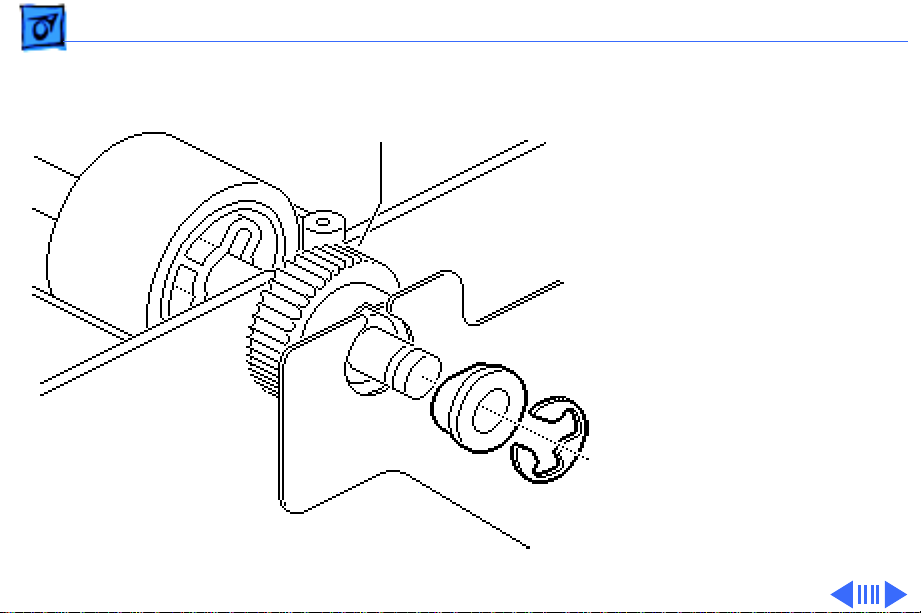
Take Apart Pickup Rollers - 18
2 Remove the E-ring from
Pickup Roller
Pickup Roller Gear
the end of the shaft and
slide the bushing from
the drive assembly plate
off the end of the shaft.
Bushing
E-Ring
Page 27

Take Apart Pickup Rollers - 19
1
2
3
Pickup Roller Gear
3 Raise the pickup roller
shaft slightly, push it
about 1/4 inch inward to
clear the bushing at the
opposite end, and remove
the shaft from the
feeder.
4 Slide the gear off the
shaft.
Note:
If you are removing
the leftmost pickup roller
from a LaserWriter Pro
600/630 envelope feeder,
remove the E-ring and
bushing on that end (not
shown here).
Page 28

Take Apart Pickup Rollers - 20
Note:
The LaserWriter 16/600 PS envelope feeder features
a one-piece pickup roller/shaft construction, so the step on
the previous page concludes the pickup roller topic. If you
are servicing a LaserWriter Pro 600/630 envelope feeder,
proceed to the steps on the following pages.
Page 29

Take Apart Pickup Rollers - 21
Note:
Steps 5 and 6 describe removal of a single roller. If
you want to remove the middle roller, repeat these steps.
5
Caution:
drops when the roller slides away.
Using your fingernails or a small jeweler's
screwdriver, release the two flex tabs, and slide the
roller off the dowel.
The dowel pin on the opposite side of the rollers
Page 30

Take Apart Pickup Rollers - 22
6 Slip the roller off the
end of the shaft, and
release the tabs at the
shaft grooves as
necessary.
Shaft Groove
Replacement Note:
The
smaller rollers and gear go
on the forward shaft and the
larger ones go on the rear.
Page 31

Take Apart Transfer Drive Assembly - 23
Transfer Drive Assembly
Before you begin, remove
the following:
• Envelope weight
• Left cover
• Right cover
• Bottom cover
• Motor
Note:
This assembly
receives rotational drive
directly from the motor and
transfers it to the pickup
and main feed shafts.
Transfer Drive Assembly
Page 32

Take Apart Transfer Drive Assembly - 24
1 Remove the E-rings and bushings at the end of the three
roller shafts.
2 Remove the three screws that secure the transfer drive
assembly to the feeder body.
3 Lift the transfer drive assembly from the feeder.
Page 33

Take Apart Separation Drive Assembly - 25
Separation Drive
Separation Drive Assembly
Assembly
Before you begin, remove
the following:
• Envelope weight
• Left cover
• Right cover
• Bottom cover
• Controller board
Page 34

Take Apart Separation Drive Assembly - 26
Note:
The separation drive assembly receives rotational
drive through the primary feed shaft. The assembly then
transfers drive through three variable action gears to the
separation assembly and secondary feed roller.
Page 35

Take Apart Separation Drive Assembly - 27
1 Remove the E-rings and bushings at the end of the three
roller shafts and the two screws that secure the drive
assembly to the feeder body.
2 Pull the assembly away from the feeder body.
Note:
Stop here if you are removing the roller shaft or
roller gear.
3 If you are replacing either of the two gears within the
assembly, you can release the gear's tab and slide it off
the spindle now.
4 If you are replacing a defective separation drive
assembly, remove the two screws securing the ground
and the ferrite core and detach the assembly from the
feeder.
Replacement Note:
integrity at this point before completing feeder reassembly.
It is a good idea to confirm drive train
Page 36

Take Apart Separation Drive Assembly - 28
Place your fingertips on the primary feed roller and rotate
it counter to paper flow. All gears and rollers within the
envelope feeder should rotate freely. (The motor must be
removed from the transfer drive assembly to decrease the
torque.) If the rollers do not rotate, make sure that all
gears and shafts are seated correctly.
Page 37

Take Apart Primary Feed Roller - 29
Primary Feed Roller
Primary Feed Roller
Before you begin, remove
the following:
• Envelope weight
• Left cover
• Right cover
• Bottom cover
• Controller board
• Separation drive
assembly
Page 38

Take Apart Primary Feed Roller - 30
Note:
The primary feed roller is the 2-inch wide roller
visible at the bottom of the three-pronged paper guide. The
primary feed shaft is responsible for tranferring drive
across the width of the feeder to the separation drive
assembly.
Page 39

Take Apart Primary Feed Roller - 31
1 Slide the primary feed shaft about an inch away from the
motor side of the feeder and let the gear at that end drop
free.
2 Raise the shaft a short distance and slide the shaft back
and out the motor side of the feeder. Catch the gear on the
opposite end as it falls off the shaft.
Page 40

Take Apart Primary Feed Roller - 32
3
Note:
The primary feed roller has a pinless connection
(see "Slip Torque Rollers" in Basics). The roller is
secured laterally by small tabs that snag the groove in
the metal shaft.
Hold the shaft upright with the roller on the high end.
4 Using your fingernails, release the two small tabs and
slide the roller off the shaft.
Page 41

Take Apart Secondary Feed Roller - 33
Secondary Feed Roller
Before you begin, remove
Secondary Feed Roller
the following:
• Envelope weight
• Left cover
• Right cover
• Bottom cover
• Controller board
• Separation drive
assembly
Note:
Due to the solid shaft/
roller design, rollers cannot
be ordered separately.
Page 42

Take Apart Secondary Feed Roller - 34
1 Remove the E-ring and bushing at the end of the shaft
near the motor and slide the shaft out of the positioning
hole.
2 Raise the shaft a short distance and slide the shaft back
and out the motor side of the feeder. Catch the gear on the
opposite end as it falls off the shaft.
Page 43

K
Service Source
Exploded V ie w
Envelope Feeder
Page 44
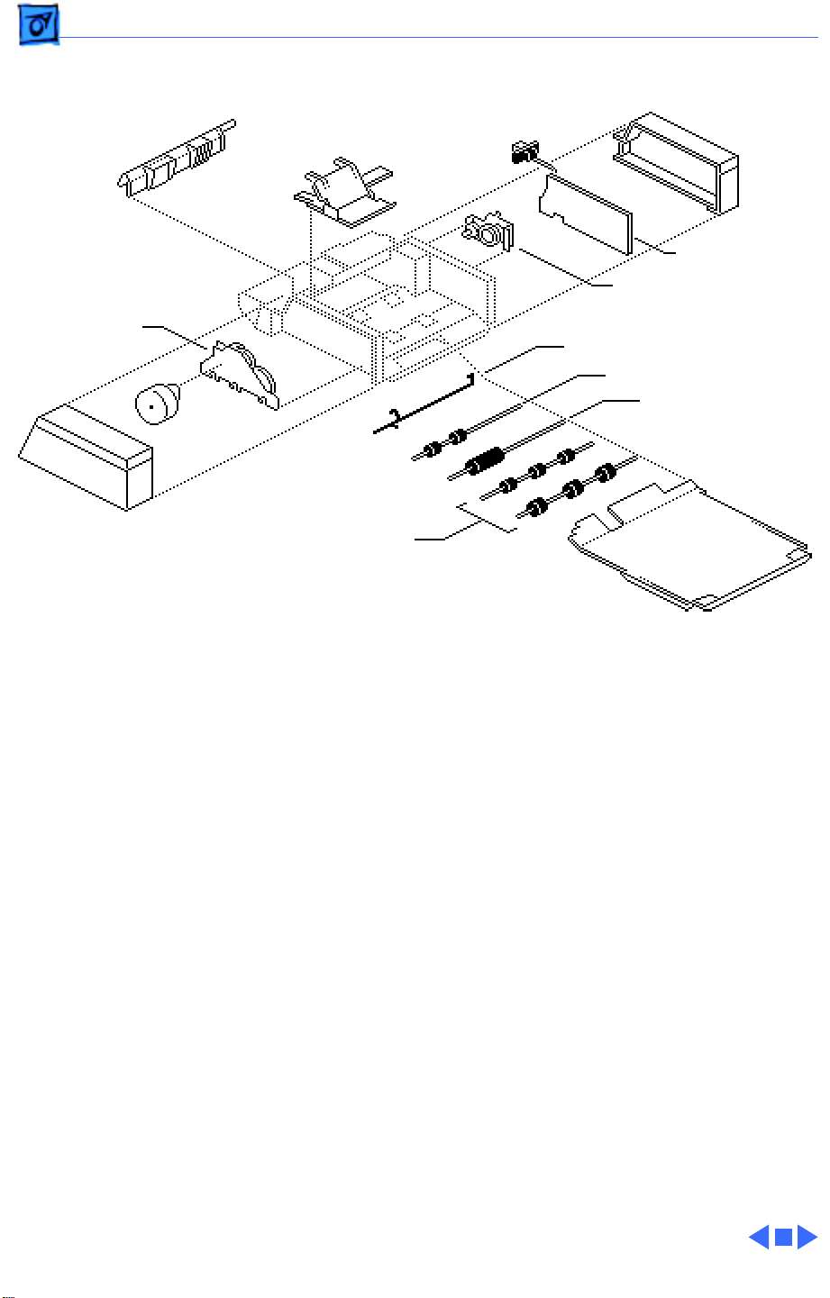
Exploded View 1
Exploded View
Front Cover
Transfer Drive
Assembly
Left Cover
Motor
Envelope
Weight
Pickup Rollers
Printer
Interface
Cable
Right Cover
Controller Board
Separation Drive
Assembly
Sensing Arm
Secondary Feed Roller
Primary Feed Roller
Bottom Cover
Page 45

K
Service Source
Additional Procedures
Envelope Feeder
Page 46

Additional Procedures Expansion Post Connectors - 1
Expansion Post Connectors
Note:
This printer has
several cable receptacles
that are secured to the
Cross Section
Fin
Expansion Post
Connector
Fin
printer by finned post
connectors. The fins expand
when you insert the
connector, but once the
connector is installed it can
be difficult to remove.
Listed on the next page are
some removal tools that you
can try.
Page 47

Additional Procedures Expansion Post Connectors - 2
• Fingers
• Small bent-nose pliers
• Grip-rings forced around the post in collar fashion
• 5 mm nut driver
Page 48

K
Service Source
Adjustments
Envelope Feeder
Page 49
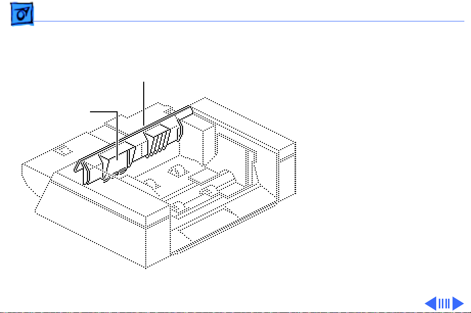
Adjustments Separation Guide Opening - 1
Separation Guide
Separation Guide
Opening
Front Cover
Opening
Note:
If you have removed
the separation guide plate
from the front cover, you
must adjust the gap between
the separation guide plate
and the primary feed roller.
Page 50

Adjustments Separation Guide Opening - 2
1 Loosen the screw that
secures the guide plate to
the front cover.
2 Insert a 1 mm and 0.5
mm thickness gauge
Separation
Guide Plate
between the guide plate
and the primary feed
roller.
3 Tighten the screw.
Thickness Gauges
1.5 mm
Primary Feed Roller
 Loading...