

Page 1

K
Service Source
LaserWriter Pro 600/630
LaserWriter Pro 600, LaserWriter Pro 630
Page 2

K
Service Source
Basics
LaserWriter Pro 600/630
Page 3
Basics Product Information - 1
Product Information
The printers covered in this
manual are the LaserWriter
Pro 600 and LaserWriter
Pro 630. Except for the I/O
boards, all parts are
identical between the two
models.
Page 4

Basics Product Information - 2
Note:
Refer to the following chapters in the Envelope Feeder
LW Pro-LW 16/6 and Sheet Feeder LW Pro-LW 16/6
manuals for additional information on feeder options.
– Take-Apart
– Additional Procedures
– Adjustments
– Illustrated Parts
Page 5

Basics LaserWriter Utility - 3
LaserWriter Utility
Note:
Refer to the user's guide for complete information
regarding LaserWriter Utility. This application gives you
software control over the LaserWriter Pro that is essential
to its operation. Some of features of LaserWriter Utility
include:
– Naming the printer
– Setting default printer resolution
– Turning on FinePrint
– Turning on PhotoGrade (if available)
– Setting default paper-handling options
– Setting print density
– Setting communication protocols
– Printing configuration page
– Turning off the startup test page
Note:
You must use LaserWriter Utility version 7.4 or
Page 6

Basics LaserWriter Utility - 4
later. You can override some default settings through the
Print dialog (LaserWriter driver version 7.2 or later).
Page 7

Basics Paper Path - 5
Paper Path
There are four paper
Optional
*
Standard
Cassette (250)
Optional Sheet
Feeder (500)
Envelope
Feeder (75)
Multipurpose
Tray (100)
sources and one output tray
in a complete system. The
number in parenthesis is
the capacity of the paper
source.
Note:
The asterisk at the
point where the paper paths
meet denotes a synchronization pause. See PS602
in “Sensing System Theory”
in this chapter.
Page 8

Basics Mechanical Drive Theory - 6
Mechanical Drive
M1
M3
M2
M4
Theory
There are four motors and
four separate drive trains in
a complete system. Two are
in the printer engine and one
is in each of the optional
feeders.
• M1 Main Motor
• M2 Pickup Block Motor
• M3 Sheet Feeder Motor
• M4 Envelope Feeder
Motor
Page 9

Basics Mechanical Drive Theory - 7
M1 Main Motor Drive
Power
Supply
Toner Cartridge
Transfer Roller
DC Controller Board
Connecting Cable
Main Motor
Drive Assembly
D
Fuser Assembly
Gears/Rollers
E
Delivery Roller Assy
Gears/Belt/Rollers
A
The main motor powers the
system that transports
paper from the toner
cartridge to the delivery
tray on top of the printer.
B
Note:
The letters next to the
boxes correspond to the
C
labels in the mechanical
drive animations that are
available on the CD.
F
G
Page 10

Basics Mechanical Drive Theory - 8
M2 Pickup Block Motor Drive
Power
Supply
DC Controller Board
Connecting Cable
Pickup Controller Board
A
The pickup block motor
powers the system that
transports paper into the
engine, through the pickup
H
block, and up to the toner
cartridge.
Pickup
Solenoids
Pickup Sensor Board
Pickup Block Motor
Gear/Roller System
J
Note:
The DC controller
board does not connect
K
directly to the pickup block
motor. Make sure to
troubleshoot the three
intermediate blocks if there
is a failure in pickup block
drive. Ê
Page 11

Basics Mechanical Drive Theory - 9
M3 Sheet Feeder Motor Drive
Power
Supply
ENGINE
SHEET FEEDER
DC Controller Board
Connecting Cable
Pickup Controller Board
Connecting Cable
Controller Block
Feeder Controller Board
Sheet Feeder Motor
A
The sheet feeder motor
powers the system that
transports paper from the
H
500-sheet cassette upward
into the printer engine.
Note:
Once the paper
L
reaches the lower feed
roller in the pickup block,
M
engine components supply
mechanical drive.
N
Pickup
Solenoid
Gear/Roller System
Page 12

Basics Mechanical Drive Theory - 10
Power
Supply
ENGINE
ENV FEEDER
Pickup
Rollers
DC Controller Board
Connecting Cable
Pickup Controller Board
Connecting Cable
Connecting Cable
Feeder Controller Board
Feeder Controller Board
Envelope Feeder Motor
Drive Assembly
Primary Feed Roller
Separation Drive Assy
A
M4 Envelope Feeder Motor Drive
The envelope feeder motor
H
O
P
Q
powers the system that
separates envelopes and
feeds them into the printer
engine.
Note:
Once an envelope
reaches the upper feed
rollers in the pickup block,
engine components supply
mechanical drive.
Page 13

Basics Sensing System Theory - 11
Sensing System Theory
There are six paper sensors, one dual-purpose sensor, and
seven sensing switches in a LaserWriter Pro 600/630 PS
system:
Paper Sensors
– PS601: Cassette Paper Sensor
– PS602: Registration Paper Sensor
– PS701: Multipurpose Paper-End Sensor
– PS702: Multipurpose Paper-Present Sensor
– PS851: Sheet Feeder Paper-Present Sensor
– PS931: Envelope Paper-Present Sensor
– PS201: Delivery/Interlock Sensor
Sensing Switches
– SW601: Top Cover Interlock Switch
– SW603: Upper Cassette Size Sensing Switch
Page 14

Basics Sensing System Theory - 12
– •SW604: Upper Cassette Size Sensing Switch
– •SW605: Upper Cassette Size Sensing Switch
– •SW851: Lower Cassette Size Sensing Switch
– •SW852: Lower Cassette Size Sensing Switch
– •SW853: Lower Cassette Size Sensing Switch
Page 15

Basics Sensing System Theory - 13
Actuator
OPEN
CLOSED
Photointerrupter
Paper Sensors
Paper sensors consist of an
actuator, a U-shaped photo
interrupter, and circuitry.
Sensors are tripped as the
actuator swings against
movement of paper and
blocks the gap of the U. An
actuator can be passive
(governed by gravity) or
spring-loaded.
Note:
Sensor failure can be
either mechanical or
electrical. When
troubleshooting sensors,
first confirm that the arm
Page 16

Basics Sensing System Theory - 14
or lever moves freely without snagging, that any springs are
applying correct resistance, and that the actuator is not
broken. Then check that all cable connections are secure. If
you have eliminated mechanical issues, proceed with
electrical troubleshooting.
Page 17

Basics Sensing System Theory - 15
PS601
Cassette Paper Sensor
Actuator: A passive lever in
the sensor holder assembly
is tripped by insertion of a
loaded cassette tray.
Sensor
Holder
Assembly
PS601
Paper
Pickup Block
Page 18

Basics Sensing System Theory - 16
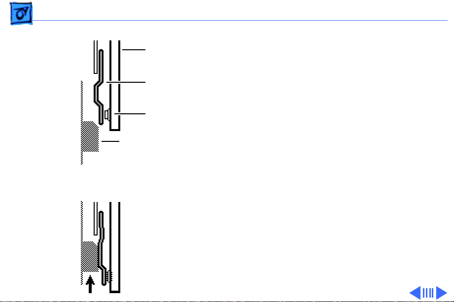
PS602
Registration Paper Sensor
Actuator: A spring-loaded
lever in the sensor holder
assembly is tripped by
arriving paper.
Sensor
Holder
Assembly
PS602
Paper
Pickup Block
All paper stops at PS602
and waits for proper
synchronization with drum
rotation and mechanical
drive.
Note:
If paper does not
reach sensor PS602 within
the prescribed time after
the pickup signal is issued, a
Page 19

Basics Sensing System Theory - 17
pickup unit delay jam exists and the controller stops
printing.
If paper reaches the sensor but does not clear it within the
correct time, a pickup unit stationary jam exists. The time
allowed for paper to clear is a function of paper size, which
is detected by PS701 (for manually fed paper) and by
sensing switches (for cassette-fed paper).
Page 20

Basics Sensing System Theory - 18
PS702
Multipurpose PaperPresent Sensor
Actuator: A spring-loaded
lever in the paper pickup
block is tripped by the
Pickup
Sensor
Board
PS702
Paper
Pickup Block
leading edge of paper as it is
loaded in the multipurpose
tray.
Page 21

Basics Sensing System Theory - 19
PS701
Multipurpose Paper-End
Sensor
Actuator: A passive lever in
the paper pickup block is
tripped by the trailing edge
Pickup
Sensor
Board
PS701
Paper
Pickup Block
of paper leaving the
multipurpose tray.
Sensor PS701 detects the
size of paper fed from the
multipurpose tray.
Page 22

Basics Sensing System Theory - 20
PS201
Delivery/Interlock Sensor
Actuator: A plastic tab on
the fuser door and a sensing
lever in the fuser assembly
Delivery/Interlock Sensor
act independently to trip a
photo interrupter.
PS201 detects two things:
paper exiting the fuser and
closure of the fuser door.
Note:
If paper does not
reach sensor PS201 within
5.2 seconds after it reached
registration sensor J602, a
delivery unit delay jam
Page 23

Basics Sensing System Theory - 21
exists and the controller stops printing.
If paper reaches the sensor but does not clear it within the
correct time, a delivery unit stationary jam exists. The
time allowed for paper to clear is a function of paper size,
which is detected by PS701 (for manually fed paper) and by
sensing switches (for cassette-fed paper).
Page 24

Basics Sensing System Theory - 22
PS851
Sheet Feeder PaperPresent Sensor
Actuator: A passive lever in
the controller block is
tripped by insertion of a
loaded cassette tray.
PS851
Controller
Block
Page 25

Basics Sensing System Theory - 23
PS931
Envelope Feeder PaperPresent Sensor
Actuator: A spring-loaded
lever is tripped by
placement of envelopes into
the feeder.
Page 26
Basics Sensing System Theory - 24
Circuit Board
Leaf Spring
Microswitch
Actuator
Microswitch ON
Microswitch OFF
Sensing Switches
Sensing switches attach to a
circuit board and do not use
photo interrupters.
Switches are actuated by leaf
springs that press inward as
you insert a cassette tray or
close the top cover.
Failure in sensing switches
can be either mechanical or
electrical. When
troubleshooting switches,
first confirm that the
actuator has not broken off
and then confirm that the
leaf springs are not bent or
Page 27

Basics Sensing System Theory - 25
misshapen. You should be able to press the leaf spring with
your finger and hear the clicking of the microswitch.
If you have eliminated mechanical issues, proceed with
electrical troubleshooting.
Page 28

Basics Sensing System Theory - 26
SW601
Top Cover Interlock Switch
Actuator: A tab on the top
cover actuates a leaf spring
Cover Interlock Arm
Cover Interlock Spring
Cover Interlock Actuator
SW601
Pickup
Controller
Board
Paper
Pickup Block
and pin, which press the
microswitch on the pickup
controller board. See
“Troubleshooting Tips” in
Troubleshooting for
information on defeating the
top cover interlock switch.
Page 29

Basics Sensing System Theory - 27
Cassette
(None)
Legal
Letter
A4
Executive
B5
SW603 SW604 SW605
OFF OFF OFF
ON ON
ON ON
OFF
OFF
OFF OFF
OFF
OFF
ON ON
ON
OFF
ON
Paper
Pickup Block
Pickup
Controller
Board
SW603
SW604
SW605
SW603/4/5
Cassette Size Sensing
Switches (Upper)
Actuator: Plastic tabs on the
side of the cassette trays
actuate leaf springs, which
press microswitches on the
pickup controller board.
The tab/switch configurations are as shown.
Note:
See the next page for a
note regarding the 250sheet universal cassette.
Page 30
Basics Sensing System Theory - 28
SW851/2/3
Cassette Size Sensing
Switches (Lower)
Actuator: Plastic tabs on the
side of a cassette tray
actuate leaf springs, which
Sheet Feeder
Controller Board
SW851
SW852
SW853
press microswitches on the
sheet feeder controller
board.
Note:
The sheet feeder uses
a 500-sheet universal
cassette. As with the upper
250-sheet universal
cassette, the tabs are set
manually by adjusting a
selection dial on the cassette.
Page 31

Basics Sensing System Theory - 29
When you are troubleshooting, be aware that human error
can be a factor in paper-size sensing for these universal
cassettes.
Page 32

Basics Hard Drives - 30
Hard Drives
Note:
Refer to the user's guide for initialization
requirements for previously used hard drives.
External Hard Drives
You can connect up to seven external hard drives to the
LaserWriter Pro 630. You cannot connect a SCSI device to
the LaserWriter Pro 600. The SCSI ID assigned to the
LaserWriter Pro 630 is 6. Any SCSI device connected to the
printer must have a different number.
Caution:
communication parameters. It is not a SCSI ID switch.
The push button switch is for configuring
Page 33

Basics Hard Drives - 31
Internal Hard Drives
Internal hard drives are currently available only through
third-parties. They should come with mounting bracket,
data cable, and documentation.
The data cable for an internal hard drive connects into J1 on
the LaserWriter Pro 630 I/O board. Connector J1 is a 40
pin connector with non-standard 2 mm pin spacing.
Page 34

Basics Test/Configuration Pages - 32
Test/Configuration Pages
There are three special pages that an operational
LaserWriter Pro 600/630 can print. Each indicates
information that can isolate problems and/or identify the
configuration of the printer.
Startup Test Page
The printer generates a startup test page 2-3 minutes after
you switch on the printer. Successful printing of this page
indicates that the I/O board is operational.
Note:
The startup test page may not print due to
software disabling (see “LaserWriter Utility” in
Basics).
Page 35

Basics Test/Configuration Pages - 33
Service Test Page
The printer generates a service test page when you press the
service test page button. Successful printing of this page
indicates that the printer engine is operational.
Configuration Page
The printer generates a configuration page when you issue
the "Print Configuration Page" command with LaserWriter
Utility.
Page 36

Basics Test/Configuration Pages - 34
Ê
Startup Test Page
Printer Name
I/O Board
Type
Communication parameters and printer control
language selected for an individual printer port
ROM
version
Installed RAM
Number of pages
the I/O board has
produced
Other startup icons
FinePrint enabled
PhotoGrade enabled
Hard Drive on-line
600 dpi enabled
Optional feeders
installed
Page 37

Basics Test/Configuration Pages - 35
Service Test Page
To access the service test
page button, open the
multipurpose tray. The
button is located in the
upper right corner of the
opening. The button is small
and difficult to see against
the black plastic. Use a
paper clip or similar tool to
press the button.
Page 38

Basics Test/Configuration Pages - 36
The service test page pattern
is a series of vertical lines
that cover the imageable
area of the page.
Page 39

Basics Test/Configuration Pages - 37
Configuration Page
This page provides the
following information to the
service technician.
• Network address settings
(1)
• Amount and allocation of
RAM memory and readout
of EEPROM integrity (2)
• Switch configurations
(3)
• HP LaserJet® emulator
version (4)
• Startup page setting (on
or off) (5)
• LaserWriter serial
number (6)
Page 40

Basics Test/Configuration Pages - 38
• Timeout settings (7)
• System administrator password (8)
• SCSI ID (LaserWriter Pro 630 only) (9)
• Halftone screen settings (10)
• Default margin offsets (11)
If possible, always print a configuration page before calling
Apple Technical Assistance Center.
Page 41

Basics Configuration Switch - 39
Configuration Switch
Configuration
Switch
The communication switch
on the I/O board determines
the communication
configuration for all the
available ports.
Communication
Ports
Page 42

Basics LaserWriter Safety - 40
LaserWriter Safety
Unplug Printer
LaserWriter printers operate at high voltages. To prevent
serious injury, always switch off the printer and unplug the
AC power cord before servicing the printer.
Laser Beam Safety
Never disconnect the beam-detect cabling or laser shutter
when the printer is switched on. Also be careful not to place
screwdrivers or other shiny objects in the path of the laser
beam. The reflected laser beam, though invisible, can
permanently damage your eyes.
Never remove the cover of a laser/scanner assembly,
whether the printer is powered on or not.
Page 43

Basics LaserWriter Safety - 41
Fuser Heat
The fuser assembly rollers become very hot during printer
operation. Before servicing the fuser assembly, switch off
the printer for at least 5 minutes to allow the fuser
assembly roller to cool.
Toner Safety
Toner is a nontoxic substance composed of plastic, iron, and
a small amount of pigment. Clean skin and clothing by
removing as much toner as possible with a dry tissue, then
washing with cold water. Hot water causes toner to jell and
permanently fuse into clothing. Toner attacks vinyl
materials, so avoid contact with vinyl.
Weight
LaserWriter printers are heavy. When lifting or moving
the printer, be careful not to strain your back.
Page 44

K
Service Source
Specifications
LaserWriter Pro 600/630
Page 45

Specifications Engine - 1
Engine
Engine
Printing Method
Optical System
Resolution
Canon LBP-B270 engine
Electrophotography using single-component microfine toner
Semiconductor laser and a rotating six-faced prism scanning
mirror
LaserWriter Pro 600: 600 dpi*
LaserWriter Pro 630: 600 dpi (300 dpi when PhotoGrade is
enabled)
Note:
The LaserWriter Pro 600 requires 8 MB of RAM in
order to print in PhotoGrade or to print at 600 dpi.
Page 46

Specifications Engine - 2
Dimensions
Clearance Required
Weight
Operating Environment
Power Consumption
Height: 11.61 in. (295 mm)
Width: 16.69 in. (424 mm)
Depth: 16.37 in. (416 mm)
50.4" x 24.25" x 19.75" high (1282 x 616 x 501 mm)
Printer with cassette: 40.7 lb. (18.5 kg):
Toner cartridge: 3.3 lb. (1.5 kg)
Temperature: 50-90.5° F (10-32.5° C)
Humidity: 20-80% relative humidity
Atmospheric Pressure: 570-760 mmHg
Approximately 0.66 kW at 71° F (20° C)
Page 47

Specifications Engine - 3
Printing Speed
Duty Cycle
Consumables Service Life
8 pages per minute (letter or A4)
6 envelopes per minute (optional envelope feeder)
No limit in pages per month
Pickup Rollers: 200,000 pages
Separation Pad: 200,000 pages
Fuser Assembly: 200,000 pages
Transfer Roller: 200,000 pages
Exhaust Fan: 25,000 hours
Note:
Replace the multipurpose pickup roller and separation
pad together. The separation pad is contained in the
multipurpose tray guide assembly.
Page 48

Specifications Engine - 4
Macintosh Requirement
Printable Area (in inches)
System Software 6.0.5 or later
US Letter: 8.11 by 10.79
US Legal: 8.11 by 13.79
A4: 7.89 by 11.44
B5: 6.72 by 9.81
Page 49

Specifications I/O Board - 5
I/O Board
CPU
RAM
ROM
Expansion
Motorola 68030 (25 MHz)
LaserWriter Pro 600: 8 MB, expandable to 32 MB *
LaserWriter Pro 630: 8 MB, expandable to 32 MB
Note:
In early 1993 some LaserWriter Pro 600's shipped
with 4 MB of RAM and a free upgrade kit that dealers were
instructed to install. No LaserWriter Pro in the marketplace
was to have been sold with less than 8 MB of RAM.
2 MB standard
40-pin processor direct slot (PDS) provided
Page 50

Specifications I/O Board - 6
Pinouts
Settings
Imaging Languages Supported
LaserWriter Pro 600:
LocalTalk, RS-232, Centronics
LaserWriter Pro 630:
LocalTalk, RS-232, Centronics, SCSI, Ethernet
Use configuration switch or LaserWriter Utility to set
communication protocols. The setting of the configuration
switch affects the configuration of all the pinouts. See the
user's guide for switch settings.
QuickDraw, PostScript Level 2, and HP PCL 4
Page 51

Specifications Sheet Feeder - 7
Sheet Feeder
Dimensions
Height: 5.19 in. (132 mm)
Width: 16.38 in. (416 mm)
Depth: 18.50 in. (470 mm)
Weight
12.98 lb. (5.9 kg) with cassette
Power Consumption
24 VDC
supplied by printer
PAGEBREAK
Page 52

Specifications Envelope Feeder - 8
Envelope Feeder
Dimensions
Weight
Power Consumption
Height: 5.03 in. (127.8 mm)
Width: 12.04 in. (306.5 mm)
Depth: 11.53 in. (293 mm)
5.72 lb. (2.6 kg)
24 VDC supplied by printer
Page 53

Specifications Paper - 9
Paper
Input Sources and Capacities
Output Source
Paper Sizes
Standard cassette (250)
Multipurpose tray (100)
Lower cassette (500)
Envelope feeder (75)
Face-down delivery tray
Standard Cassette:
A4, B5, legal, letter, or executive plain paper (16-24 lb.)
Cassettes available: letter, A4, or universal
Multipurpose Tray
Plain paper from 7.16 in. by 10.1 in. to 8.5 in. by 14 in. (16-
32 lb.), envelopes, and fuser-compatible labels and film
Page 54

Specifications Paper - 10
Lower Cassette
A4, B5, legal, letter, or executive plain paper (16-24 lb.)
Cassette available: universal
Envelope Feeder
COM-10, DC, Monarch, C5, B5 (recommended envelope); from
3.54 in. by 7.44 in. to 7.0 in. by 10.0 in.
Note:
Do not use envelopes with clasps, snaps, windows, or
synthetic materials. Envelopes with peel-off adhesive strips
or double sealable flaps must use fuser-compatible adhesive.
Page 55

K
Service Source
Troubleshooting
LaserWriter Pro 600/630
Page 56

Troubleshooting General - 1
General
Troubleshooting contains quick-reference troubleshooting
information for the LaserWriter 600/630. We encourage you to
review and print out this chapter before troubleshooting a
printer.
At the end of this chapter are troubleshooting flowcharts and
tables. If a table name clearly addresses your problem, you can go
directly to that table. If not, you should go to the flowchart
associated with the version of the printer you are working on.
Page 57

Troubleshooting Printer Diagnostic - 2
Printer Diagnostic
To enable the printer diagnostic, switch off the printer, jumper
pins 7 and 9 on the I/O board DB-9 connector, and switch on the
printer. Under normal conditions, LEDs should flash during
startup for about 15 seconds and then fix on the "diagnostic
executing" configuration for about 2 minutes.
9
Jumper
7
Diagnostic Executing
No Error Found
Page 58

Troubleshooting Printer Diagnostic - 3
If no error is found, all LEDs come on and two pages print. See
next page for "error-found" configurations.
Note:
If the "diagnostic executing" LEDs persist longer than 3
minutes, an unknown error exists.
An "error-found" configuration could indicate a fault anywhere
from the DC controller outward to the module or component. Go to
the topic in Flowcharts that corresponds to the error.
Page 59

Troubleshooting Printer Diagnostic - 4
Ê
I/O Board Error
Fuser Assembly Error
Laser/Scanner Erro
Main Motor Erro
Fan Error
ROM #1 Error
ROM #2 Error
ROM #3 Error
ROM #4 Error
SIMM #1 Error
SIMM #2 Error
Page 60

Troubleshooting Maintaining I/O Connectivity - 5
Maintaining I/O Connectivity
Remove the printer interface cable and temporarily install a
Quadra 900/950 floppy drive 20-pin cable between connectors A
and B in the diagram on the next page. This cable has the extra
length needed for the I/O shield to rest flat on the work surface.
Note:
Do not disconnect power supply cable J15, the I/O-CPU
cabling, or the AC power cable.
Page 61

Troubleshooting Maintaining I/O Connectivity - 6
Ê
Maintaining
I/O Connectivity
A
J15
B
Page 62

Troubleshooting Troubleshooting Tips - 7
Troubleshooting Tips
Multimeter Probes
The connectors within the LaserWriter 600/630 are very small
and require sharp needle-point probes to make good contact. Do
not use probes that do not make proper contact. To see whether a
set of probes works properly, test resistance at connector J210
on the DC controller board in the manner described below (the
cable must connected to the board).
Set your multimeter to resistance and insert the probes at pins 1
and 10. If the reading indicates continuity then the probes are
making good contact. If the reading indicates infinite resistance,
then the probes do not make contact and should not be used with
this printer.
Page 63

Troubleshooting Troubleshooting Tips - 8
Forcing a Feed Cycle
If you want to print from anything other than the standard 250sheet cassette tray, you must be connected to a CPU and select the
feed option that you want. It is not possible to print a service test
page from any source other than the standard cassette.
Page 64

Troubleshooting Troubleshooting Tips - 9
Interrupting a Print Cycle
Interrupting a print cycle and inspecting the photosensitive drum
can help isolate the cause of print quality problems. If the image
on the surface of the drum exhibits the same problem as the
printed page, the fault is before the drum, probably in the
imaging system.
If the image on the drum is OK, the fault is after the drum,
probably in the fuser assembly, transfer block, or high-voltage
power supply. To inspect the drum in this way, run a print and
wait until the paper clears the synchronization pause at the
registration paper sensor. Open the toner access door, remove the
toner cartridge, and pull back the shield to inspect the drum.
Page 65

Troubleshooting Troubleshooting Tips - 10
Maintaining Pickup Connectivity
To troubleshoot the paper pickup block, you must temporarily
reconfigure the printer’s paper path so that the pickup block is
exposed. In this reconfigured state, you will be able to take
voltage readings from the pickup controller board and observe
paper feeding from the cassette.
Note:
Since paper will jam due to the disruption of the paper
path, you must disable the startup test page (see “Printer
Utilities” in Basics) before turning the printer back on. Make
sure to enable the startup test page before returning the printer
to the customer.
To reconfigure the paper path, remove the pickup block, set it at
an angle to the printer, and reconnect cables J601 and J603 at the
leading edge of the pickup controller board. Insert the cassette
tray into the pickup block. Press down the top cover interlock
actuator and force the interlock switch closed by wedging in the
Page 66

Troubleshooting Troubleshooting Tips - 11
hooked end of the green cleaning brush. Reinstall the top cover and
cover liner and close the lid.
If you want to test pickup from the multipurpose tray or the
envelope feeder, you must maintain I/O connectivity (see
previous topic). You cannot run a service test page from any
source other than the standard 250-sheet cassette.
Caution:
the metal chassis when performing this procedure.
Do not let the pickup controller board brush up against
Page 67

Troubleshooting Troubleshooting Tips - 12
Defeating the Top Cover Interlock
You may occasionally need to defeat the top cover interlock to
simulate a “top cover shut” condition. To defeat this sensor, open
the toner access cover and wedge a stiff, non-metallic insert into
the interlock switch opening. Push the insert down to depress the
interlock leaf spring.
Page 68

Troubleshooting Troubleshooting Tips - 13
Defeating the Fuser Door Interlock
You may occasionally need to defeat the fuser door interlock to
simulate a “fuser door shut” condition (for example if you wanted
to observe paper as it exits the fuser rollers). To defeat this
sensor, open the fuser access door and wedge the brush end of the
green cleaning brush into the delivery/interlock sensor.
Green Cleaning Brush
Page 69

Troubleshooting Troubleshooting Tips - 14
Caution:
removing the brush, make sure that the delivery sensing arm
moves freely and is not snagged.
Do not insert the brush too far into the sensor. After
Page 70

Troubleshooting Troubleshooting Tips - 15
Sheet Feeder Bypass
You can visually troubleshoot a functioning stand-alone sheet
feeder by bypassing connector J603 on the printer’s pickup
controller board.
Disable the startup test page, and remove the top cover, rear
panel, and right corner panel from the printer. Disconnect J603
from the exposed edge of the pickup controller board and connect a
spare sheet feeder interface cable (P/N 922-0219). Plug the
opposite end of the interface cable into the sheet feeder receptacle.
Page 71

Troubleshooting Troubleshooting Tips - 16
Observing Envelope Feed
You can visually inspect and/or take multimeter readings from a
fully functioning envelope feeder. Remove the covers of the feeder
and install it into the printer. The feeder will operate in normal
fashion.
Envelope Feeder
(without covers)
Page 72

Troubleshooting Troubleshooting Tips - 17
Drum Exposure
Cover the toner cartridge when you remove it from the printer.
Prolonged exposure to light can result in print quality problems.
If this has occurred, store the toner cartridge in a dark place. The
drum will return to its normal condition after about 24 hours.
Page 73

Troubleshooting Capacitor Discharge - 18
Capacitor Discharge
When there is a failure of the fusing system, the DC controller
board shuts off current to the fuser roller heater and charges
capacitor C202 to prevent overheating. If there is a failure of the
fusing system, you must turn the power off for about 10 minutes
or manually discharge the capacitor before switching power back
on.
DC Controller Board
C202
Page 74

Troubleshooting Capacitor Discharge - 19
Caution:
before performing this procedure.
To discharge capacitor C202, switch off the printer and remove
the rear panel and I/O shield. Carefully jumper the two wires at
the base of the capacitor using some kind of conductor.
Note:
the capacitor: a flat blade screwdriver, paper clip, or aluminum
foil doubled over. The tool illustrated is a length of lead solder. It
has the advantage of being ductile and is less apt to damage the
controller board.
Be sure to switch off power and unplug the printer
There are many different tools that can be used to discharge
Page 75

Troubleshooting Capacitor Discharge - 20
Discharging
Capacitor C202
C202
Page 76

Troubleshooting Fuser Roller Modes - 21
Fuser Roller Modes
Two small levers at each end of the fuser set the fuser rollers into
either print mode or jam-release mode. Apple ships the printer
with the rollers in jam-release mode. Failure to set these levers
into print mode will cause loose toner or smudging problems.
Print Mode:
Engage the fuser rollers by setting the two levers in a "DOWN"
position.
Jam-Release Mode:
Disengage the rollers by setting the two levers in an "UP"
position.
Page 77

Troubleshooting Fuser Roller Modes - 22
Fuser Assembly
Left
Lever
Right
Lever
Page 78

Troubleshooting Expansion Post Connectors - 23
Expansion Post Connectors
The LaserWriter 600/630 has several cable receptacles that are
secured to the printer by finned post connectors. The fins expand
when you insert the connector, but once the connector is installed
it can be difficult to remove.
If you cannot remove these connectors with your fingers, try
small bent-nose pliers, a 5 mm nut driver, or grip-rings forced
around the post.
Caution:
upside-down, they will not couple properly.
The cable receptacles are keyed. If you install them
Page 79

Troubleshooting Expansion Post Connectors - 24
Fin
Cross Section
Fin
Expansion Post Connector
Page 80

Troubleshooting Circuit Board Diagrams - 25
Circuit Board Diagrams
On the following pages are diagrams of the circuit boards and
high-voltage contacts listed below:
• LaserWriter Pro 600 I/O Board
• LaserWriter Pro 630 I/O Board
• DC Controller Board
• Pickup Controller Board
• Pickup Sensor Board
• High-Voltage Power Supply
• Envelope Feeder Controller Board
• Sheet Feeder Controller Board
Page 81

Troubleshooting Circuit Board Diagrams - 26
Configuration Switch
LocalTalk
RS-232 (Serial)
Centronics (Parallel)
LW Pro 600 I/O Board
J1 J2
SIMMs
J10
J11
ROMs
J13
PDS
J15
ROM SIMM Slot
Page 82

Troubleshooting Circuit Board Diagrams - 27
Configuration Switch
SCSI
LocalTalk
RS-232 (Serial)
Ethernet
Centronics (Parallel)
LW Pro 630 I/O Board
J1 J2
SIMMs
J10
J11
PDS
1234
ROMs
J13
J15
ROM SIMM Slot
Page 83

Troubleshooting Circuit Board Diagrams - 28
J202
J201
J213
J203
J204 J205
C201 C202
TB201
DC Controller Board
VR202 (see "Registration Adjustment"
in Adjustments.)
J206
J207
J208
J213
J209
J210J211
Page 84

Troubleshooting Circuit Board Diagrams - 29
Service Test
Page Button
Cover Interlock
J604
J605
Cassette Size
Microswitches
SW601
Switch
SW602
SW603
SW604
SW605
J601
J603
J602
Pickup Controller Board
J604
J605
Page 85

Troubleshooting Circuit Board Diagrams - 30
J704
J703
J702
PS702
Multipurpose Tray
Paper-Present
Sensor
Multipurpose Tray
Paper-End
PS701
Sensor
Pickup Sensor Board
Pickup Controller
Board Receptacle
J701
Page 86

Troubleshooting Circuit Board Diagrams - 31
J402
VR401
TB406
TB405
TB403TB404
High-Voltage Power Supply
PS Interface Board
Receptacle
J401
TB402 TB401
Page 87

Troubleshooting Circuit Board Diagrams - 32
Envelope Feeder
Controller Board
J931
PS931
J932
Page 88

Troubleshooting Circuit Board Diagrams - 33
Sheet Feeder
Controller Board
J853 J851
PS851 J852
SW851
SW852
SW853
Tab Cutout
Cassette Size
Microswitches
Page 89

Troubleshooting Wiring Diagram - 34
Wiring Diagram
The LaserWriter 600/630 wiring diagram can be found on the
next page. The detail in this document is too small to read easily at
100% view. You should either zoom into the diagram using the
zoom tool above, or print the diagram on a laser printer with a
resolution of 300 dpi (600 dpi preferred).
Page 90

FUSER ASSEMBLY
TP1
H1
F
TONER
CARTRIDGE
PRI
GND
TR
DEV
ANTIN
GND
TRANSFER
34
12
Pickup Roller
Clutch Solenoid
UP
BLOCK
67
3
2
J136
SL851
M3
TH1
J743
A
LOW
TB406
TB402
TB401
TB405
TB403
TB404
B
A
/A
B
/B
J744
B
D742
D741
J401
J402
123
ANT
REF
GND
8
1
SW852
SW853
SW851
Cassette Size
Sensing Switches
J853
1
2
3
1
2
3
4
J852
8
8
7
7
6
6
5
5
4
4
3
3
2
2
1
1
J743
J742
B5
B5
A5
A5
B4
B4
A4
A4
B3
B3
A3
A3
B2
B2
A2
A2
B1
B1
A1
A1
HV
POWER
SUPPLY
PICKUP CONTROLLER BOARD
HIGH-VOLTAGE
CONNECTOR BOARD
13
J601
1
4
J603
1
J602
B
A
5
1
(Solder Side)
J604
J605
C
1
2
3
4
J851
PS851
Sheet Feeder
Paper-Present
Sensor
F
F
FEEDER
(Optional)
1
4
1
6
J135
SHEET
J741
10
+24VA
2NDO
2NDI
GND
ENVELOPE
FEEDER
(Optional)
9
8
7
6
5
4
3
2
1
+24VB
/TXD
+5V
/RXD
GND
SL02
GND
GNDTH
FSRTH
+24VB
+5V
TVIN
HVRST
/TVOUT
SLI2
J210
5
4
J203
3
2
1
PICKUP CONTROLLER BOARD
C
1
2
3
4
J136
A
J931
Envelope Feeder
Paper-Present Sensor
M1
J603
J604
1234
+24VA
1234
PS931
J211
GND
+24VD
1234
J131
MAIN MOTOR
GND
EBVI
EBVO
F
F
J932
1234
/MON
1
2
3
4
/MRDY
Main
Power
Switch
SW101
12
J102
POWER SUPPLY
J104
123
123456
RLD
GND
SLO1
THOUT
123456
PAP
SLI1
J601
+5V
PBP
/FSRD
123
12345678910
J212
12345678910111213
1 2 3 4 5 6 7 8 9 10 11 12 13
A
/A
M4
B
/B
LINE
INPUT
1
J101
2
3
J105
4
J103
+5V
GND
GND
GND
+24VA
TB201
J201
+5V
GND
GND
+24VA
+24VB
+24VB
DOPEN
'H' When Door
Is Open
J605
123456
GND
1STL
1STS
RESL
'L' When
Tripped
123 123
PS601 PS602
CASSETTE
PAPER SENSOR
1
2
3
4
DC CONTROLLER BOARD
+24VA
SW601
SENSOR HOLDER
GND
RESS
REGISTRATION
PAPER SENSOR
LASERWRITER PRO I/O BOARD
J15
1234567891011121314151617181920
/BD
GND
/RDY
/PPRDY
/VSREQ
1234567891011121314151617181920
GND
APCIN
APCOUT
1234567 123456 1234
LASER DRIVER
'L' When Tripped
ASSEMBLY
J2
/STS
/PCLK
/SBSY
/LON
/ENBL
/VDATA
LASER/SCANNER ASSEMBLY
GND
/PRNT
/CBSY
/VSYNC
/CPRDY
J207
+5V
/SCNRDY
/SCNON
SCANNER
MOTOR UNIT
'H' When Tripped
'L' When Tripped
A1 B1A2B2A3 B3A4B4 A5 B5
A1 B1A2B2A3 B3A4B4 A5 B5
PA
/PAMP/PB
PS701
Multipurpose
Paper-End
Sensor
PICKUP SENSOR BOARD
/CMD
+24VA
J602
PDS
1
J13
40
EXHAUST
FM1
FAN
GND
GND
GND
GND
/VDO
/CCLK
J205J206
GND
SCNCLK
M5
PB
1ST
MPS
PS702
Multipurpose
Paper-Present
Sensor
'H' When
123456781234567
+5V
J731J151J721
BEAM DETECT
IC UNIT
Service Test
Page Switch
J701
MPE
GND
+24VA
123
Tripped
/BDI
GND
SW602
J702
J703
J704
FAND
J209
J204
J208
1
2
3
1
2
3
4
1
2
GND
FLOCK
1
2
3
4
5
6
1
2
3
Sensing Switches
+24VA
MPD
GND
PA
/PA
PB
/PB
+24VA
1STD
Cassette Pickup Roller
LED
STATUS
PANEL
PSNS
123
PS201
DELIVERY/
INTERLOCK
SENSOR
SW603/4/5
Cassette Size
Multipurpose
Pickup Roller
Clutch Solenoid
Clutch Solenoid
SL702
SL701
LaserWriter Pro 600/630
Wiring Diagram
6
5
4
3
2
1
GND
M2
PSL
Page 91

Troubleshooting Connector J136 Locator - 36
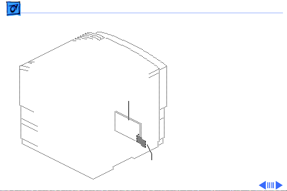
Connector J136 Locator
J136 is the connector that the envelope feeder mates into. To see
it, open the multipurpose tray and remove the closure panel. The
illustration below shows the connector as it appears from the
outside of the printer.
A voltage reading of 24V between pins 1 (+24VA) and 4 (GND)
during printer startup indicates that motor power is reaching the
envelope feeder.
34
12
Page 92

Troubleshooting Connector J743 Locator - 37
Connector J743 Locator
J743 connects the fuser assembly to the high-voltage connecting
block. A measurement of continuity between pins 1 and 8
indicates that the heater bulb and thermoprotector are intact. A
measurement of continuity between pins 6 and 7 indicates that the
thermistor is intact.
67
8
1
Connector J743
Fuser Assembly
Page 93

Flowcharts and TablesTroubleshooting
LaserWriter Pro 600/630 Troubleshooting Flowchart
START
Connect the printer to a
known-good computer,
install a toner cartridge,
and fill the cassette tray.
Does
the power supply
fan come on when
you switch on the
printer?
Yes
No
Go to Table 1.
Does
the ready LED
glow steadily after the
printer warms
up?
Yes
Try printing from each
available paper source. If
the printer does not pick up
paper, or if the paper jams,
go to Figure 3.
Is the print
quality OK?
Yes
If necessary, restore the
customer's LaserWriter
Utility settings. (For
example: Startup Page,
Automatic Tray Switching,
and Default Resolution.)
No
No
A
Go to Figure 2,
Print Quality
Problems.
PRINTER IS FUNCTIONAL
Page 94

Troubleshooting
222
2
Flowcharts and Tables
2
A
Are all
LEDs off?
No
Are
the toner-out
and paper-jam LEDs
flashing?
No
Is the toner
LED on or
flashing?
No
Is the paper-out
LED on?
Yes
Yes
Yes
Yes
Go to Table 2.
Perform the EPOST
procedure (see the
"Printer Diagnostic"
topic).
Go to Table 3.
Go to Table 4.
2
2
No
Is the paper-jam
LED on?
No
If the ready LED flashes without
stopping, disconnect the printer from
the computer, and see if the problem
persists. If you have just performed
the printer diagnostic (see the
"Printer Diagnostic" topic),
confirm that the serial loopback
connector has been removed from the
serial port.
Yes
Go to Table 5.
Page 95

T roubleshooting T ables
Flowcharts and TablesTroubleshooting
Important
As you proceed through the steps in a table, remember to retry the printer each
time you change its physical state–for example, when you replace a module. If
the problem remains, reinstall the original module before proceeding to the
next step in the table. Refer as necessary to the wiring diagram that follows the
tables
.
Table 1. The Power Supply Fan Does Not Come On When You
Switch On the Printer
Step Check Result Action
1 Does the power supply
fan come on when you
turn on the printer?
2 Do any of the motors
rotate after the printer
starts up?
No
Yes
Yes
Remove the rear panel, I/O board,
and I/O shield, and restart the printer.
The problem is probably with the
power supply fan or its connection to
the DC controller board. Run the
printer diagnostic. If the diagnostic
suggests a fan problem, see Table 9.
Check the connections at J213 and
J214 on the DC controller board, and
check that nothing physical is b locking
the fan blades. If the problem persists,
replace the DC controller board.
No
Make sure J103 is connected at the
power supply. If TB201 is detached
from the DC controller, replace the DC
controller board; otherwise, replace
the power supply. If the problem
persists, replace the DC controller
board.
Page 96

Troubleshooting
222
2
Flowcharts and Tables
Table 2. All LEDs Are Off After Printer Warmup
Step Check Result Action
1 Are the top cover and
fuser door closed?
2 Remove the rear panel
and I/O shield. Is the status panel cable securely
connected to J204 on the
DC controller board?
3 Can you print despite the
fact no LEDs illuminate?
4 Place probes between
J208-2 (GND) and J208-3
(PSNS) on the DC controller board. Does the voltage rise to 5 V as you
open the fuser door?
No Close them completely, and confirm
that the plastic tab actuators on the
doors are intact. No LEDs illuminate if
either door is open.
No Secure the cable.
Yes Check connection between the status
panel and the DC controller board. If
the connections are secure, replace
the status panel.
No Replace the delivery/interlock
assembly.
2
2
2
5 Place probes between
J201-7 (+5 V) and J201-1
(GND) on the DC controller board. Switch on the
printer. Does the voltage
measure 5 V?
6 Press the top cover inter-
lock leaf spring. Do you
hear the clicking sound of
a microswitch when you
press the spring?
7 Remove the paper pickup
block and maintain pickup
connectivity. Place
probes between J601-11
(GND) and J601-7 (+5 V)
on the solder side of the
pickup controller board.
Does the voltage measure
5 V?
No Replace the DC controller board.
No Confirm that the black plastic actuator
is in place behind the top of the pickup
controller board.
Yes
No
Replace the pickup controller board.
Replace the DC controller-board-topickup-controller-board cable.
Page 97

Table 3. Toner LED Is On or Flashes After Printer Warmup
Step Check Result Action
Flowcharts and TablesTroubleshooting
1 Try a known-good toner
cartridge. Does the
problem persist?
2 Have you recently ser-
viced the printer and has
this symptom existed
ever since?
3 Have you just performed
the engine diagnostic?
4 Remove the toner car-
tridge and inspect all the
toner contacts for damage
or excess toner buildup.
Are the contacts clean
and in good condition?
5 Remove the rear panel
and I/O shield. Place
probes between J210-6
(HVRST) and J210-10
(GND) and switch on the
printer. Does the voltage
change from 0 to 5 V
about one second after
the printer starts up?
No Problem solved.
Yes You probably did not fully reseat the
high-voltage power supply, connector
block, or transfer block assembly; or
connector J210 on the DC Controller
board is not secure. Make sure these
modules are securely installed.
Yes Confirm there is not still a serial loop-
back connector installed in the serial
port.
No Clean or repair the contacts if possi-
ble. Take special note of TB403, which
is the pronged contact that the toner
cartridge mates into. This contact ties
into the toner sensor inside the cartridge.
No
Yes
Replace the DC Controller board.
Perform the first module exchange
below . If the problem persists, reinstall
the original module and perform the
next exchange:
• Replace the HV power supply
• Replace the power supply-to HVPS interface board.
• Replace the transfer block assembly.
• Replace the DC controller-board-to HVPS cable.
Page 98

Troubleshooting
222
2
Flowcharts and Tables
Table 4. Paper-Out LED is On After Printer Warmup
Step Check Result Action
1 Is the cassette empty or not
installed?
2 Remove the cassette and
inspect the paper-sensing
lever. Is the lever broken?
3 Defeat the cassette paper
sensing lever by pushing it
and holding it in (as if a cassette were present). With
your other hand, press the
three microswitch leaf
springs all at the same time.
Does the ready LED illuminate after a couple of
seconds?
4 Remove the rear panel and
I/O shield. Place probes
between J201-7 (+5 V) and
J201-1 (GND) on the DC
controller board. Switch on
the printer. Does the v oltage
measure 5 V?
Yes Make sure that the cassette is present
and has paper.
Yes Replace the sensor holder
assembly.
Yes Replace the pickup controller board.
No Replace the DC controller board.
2
2
2
5 Remove the paper pickup
block and maintain pickup
connectivity. Place probes
between J601-11 (GND)
and J601-7 (+5 V) on the
solder side of the pickup
controller board. Does voltage measure 5 V?
6 Measure the voltage
between J605-5 (GND) and
J605-3 (1STS). Does the
voltage measure 5 V?
7 Keep the probes in the
same position and manually
trip the cassette sensor
lever. Does the voltage drop
to 0 V when you trip the
lever?
No Replace the DC-controller-to-pickup-
controller cable.
No Replace the pickup controller board.
No
Yes
Replace the sensor holder assembly.
Replace the pickup controller board.
Page 99

Flowcharts and TablesTroubleshooting
Table 5. Paper-Jam LED is On After Printer Warmup
Step Check Result Action
1 Is the delivery/interlock
sensor snagged?
2 Is the delivery-sensing lever
snagged?
3 Is the registration-sensing
lever snagged?
4 Remove the rear panel, I/O
shield, top cover, and
delivery roller assembly. Is
the purple cable between the
delivery/interlock sensor and
the DC controller board
securely connected?
Yes
Yes
Yes
No
Remove the top cov er and delivery roller
assembly, and unsnag the sensor spring.
The spring should be straight. If the
actuator is snagged, it will not spring
back and forth as you try to trip it.
Remove the top cov er and delivery roller
assembly and see what is snagging the
lever. If necessary, remove and
dismantle the fuser assembly and
replace the delivery-sensing lever.
If the lever is brok en or snagged, remov e
the pickup block and troubleshoot
further. If necessary, replace the sensor
holder assembly.
Secure the cable.
5 Place probes between J208-
2 (GND) and J208-3 (PSNS).
Does the voltage rise to 5 V
as you open the fuser door?
6 Place probes between
J201-7 (+5 V) and J201-1
(GRD) on the DC controller
board. Does the voltage
measure 5 V?
No
No
Replace the delivery/interlock assembly.
Replace the DC controller board.
Page 100

Troubleshooting
222
2
Flowcharts and Tables
Table 5. Paper-Jam LED is On After Printer Warmup (Continued)
Step Check Result Action
7 Remove the paper pickup
block and maintain pickup
connectivity. Place probes
between J601-7 (+5 V) and
J601-11 (GND) on the solderside of the pickup controller
board. Does the voltage
measure 5 V?
8 Place probes between
J605-6 (RESS) and J605-5
(GND). Does the voltage
measure 5 V?
9 Keep the probes in the same
position and manually trip the
registration sensor lever.
Does the voltage drop to 0 V
when you trip the lever?
No Replace the DC-controller board-to-
pickup-controller-board cable.
No Replace the pickup controller board.
No
Yes
Replace the sensor holder assembly.
Replace the DC controller board.
2
2
2
Important
When there is a failure of the fusing system, the DC controller board shuts off
current to the fuser roller heater and charges capacitor C202 on the DC controller board to prevent overheating. If there is a failure of the fusing system, you
must turn off the power and leave it off for about 10 minutes, or manually
discharge the capacitor before switching power back on.
Table 6. Fuser Assembly Error
Step Check Result Action
1 Remove the rear panel, I/O
board, and I/O shield. Is
connector J210 on the DC
controller board secure?
2 Is the power supply firmly
seated?
No Secure the connector.
No Seat the power supply.
 Loading...