

Page 1
Service Source
iMac G5 (17-inch)
Updated 1 October 2007
© 2005 Apple Computer, Inc. All rights reserved.
Page 2

Service Source
Take Apart
iMac G5 (17-inch)
© 2004 Apple Computer, Inc. All rights reserved.
Page 3

General Information
What’s New
October 2007
Updated Logic Board replacement procedure. A “caution” was added to notify service
providers not to twist, flex, or bend the iMac G5 logic as you install to board into the
chassis. Flexing the board may jeopardize the thermal interface between the heatsink and
the processor. Refer to the iMac logic board inbox notice 073-1158 for additional
information.
July 2006
A diecut piece of microfoam (922-7671) is included with all replacement optical drives and
display bezels. It should be installed in between the disc drive and the display bezel to
prevent optical media from ejecting out of the system and dropping to the desktop. Only
one diecut of microfoam should be used per system. Refer to the replacement procedures
in Take Apart for either the optical drive, display bezel, or microfoam shim for more
information.
Display/Bezel Assembly Elimination
Effective July 24, 2006, the Display and Bezel assembly module will no longer be available
as a single service part for the iMac G5 (17- and 20-inch models). The Display and Bezel
are now available as two separate service parts (see below) to simplify inventory and
reduce repair costs.
• 922-6796 Front Cover Assy,w/Optical Slot,iMac G5 17"
• 922-6795 Front Cover Assy,w/out Optical Slot,iMac G5 17"
• 661-3598 Panel, Display w/Brackets, iMac G5 17"
Procedures added to Take Apart (May 2005)
• Fans, Upper
• Logic board
• Speakers
• Microphone
• Bluetooth card
• Soft modem
• Chassis
General Information
iMac G5, 17-inch Take Apart -
1
Page 4

• AirPort antenna
• Bluetooth antenna
• LED light pipe
2 -
iMac G5, 17-inch Take Apart
General Information
Page 5

Tools
The following tools are required to service the computer:
• Phillips #2 screwdriver
• Flat-blade screwdriver
• Torx-6 and 8 screwdriver
• Jeweler’s flat-blade screwdriver
• Nylon probe tool (black stick 922-5065)
• Needlenose pliers
• Soft cloth (to protect removed parts from scratches)
General Information
iMac G5, 17-inch Take Apart -
3
Page 6

Important Things to Know
1. All customer removable screws are brass colored (except for some fan screws
on earlier units which use torx screws). Do not remove screws unless they are
brass colored, or you will void your warranty.
2.
Important:
you how to ground yourself.
3. A magnetized “L”-shaped Phillips screwdriver is included with the replacement part.
4. The midplane is no longer offered as a service part or as a Do-it-Yourself repair. Most
parts on the midplane are now available as individual service parts.
5. The display/bezel parts no longer offered as a service or DIY repair. The display and
front bezel are offered separately.
6. Additional items are included with these service parts:
Back Cover
• Two blank labels are included with the replacement back cover. Copy the serial
number and Ethernet number off the bottom of the computer’s foot and attach the
new labels to the bottom of the replacement foot. The back cover take apart
procedure will show you where to attach the labels.
Ground yourself when working on the computer. The procedure will show
Logic Board
• Syringe with thermal compound
• Alcohol cleaning wipe
• A new pre-printed Ethernet label is included with the midplane. Attach the sticker to
the bottom of the computer’s foot, above the existing label.
• A blank serial number label is included with the midplane. Copy the serial number
off the bottom of the computer’s foot and attach the new label to the midplane. The
midplane take apart procedure will show you where to attach the label.
7. Do not pull on individual wires when disconnecting a part; pull on the connector.
8. A screw chart is attached at the end of this document. Use the chart to identify screw
type and screw locations.
4 -
iMac G5, 17-inch Take Apart
General Information
Page 7
Removing the Back Cover
Tools
Use the screwdriver provided, or a Phillips #2 screwdriver
Procedure
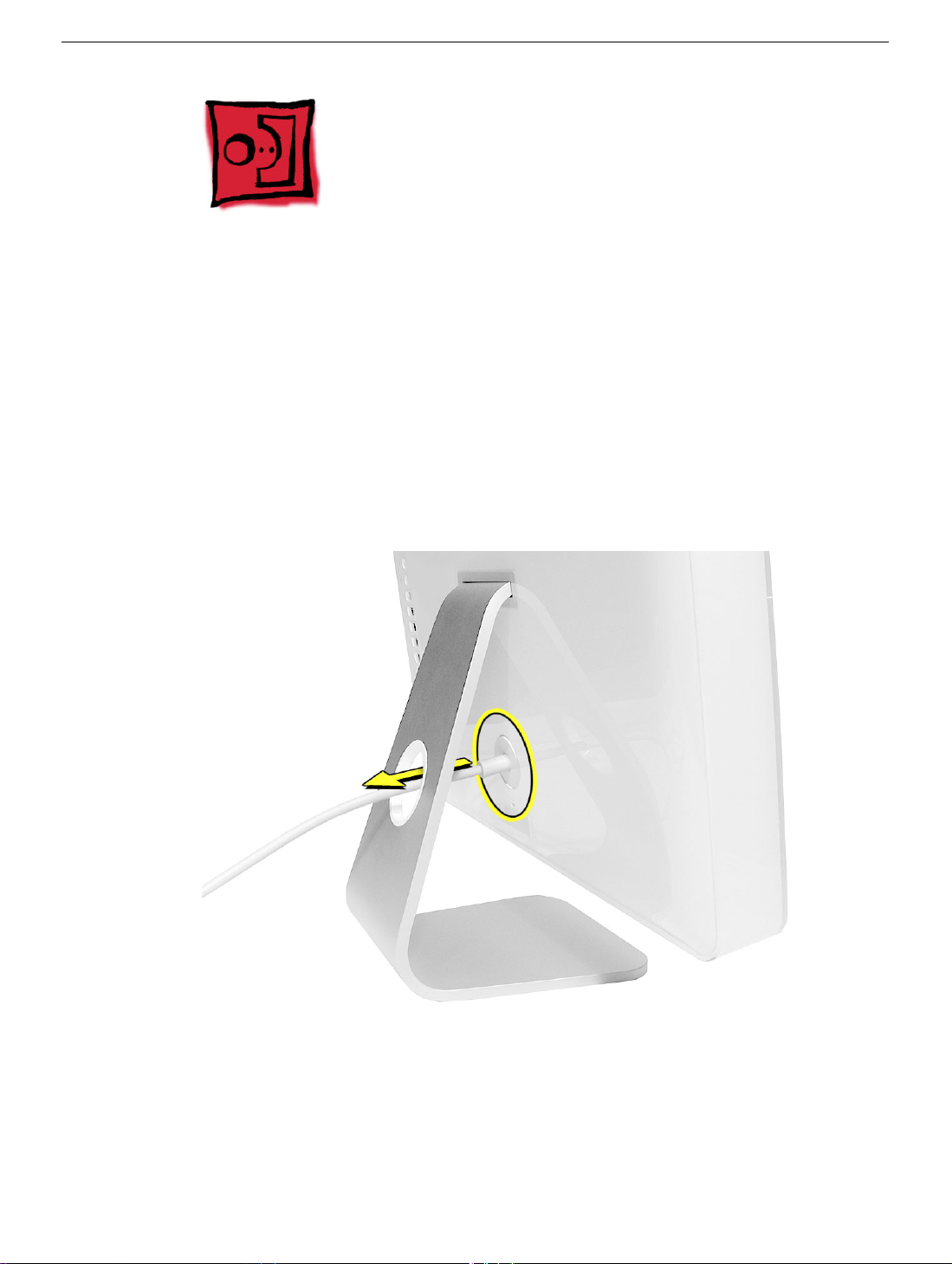
1. Turn your computer off by choosing Shut down from the Apple (K) menu.
2. Disconnect all cables, and unplug the power cord from your computer. Put on your
ESD Wrist strap.
Removing the Back Cover
iMac G5, 17-inch Take Apart -
5
Page 8
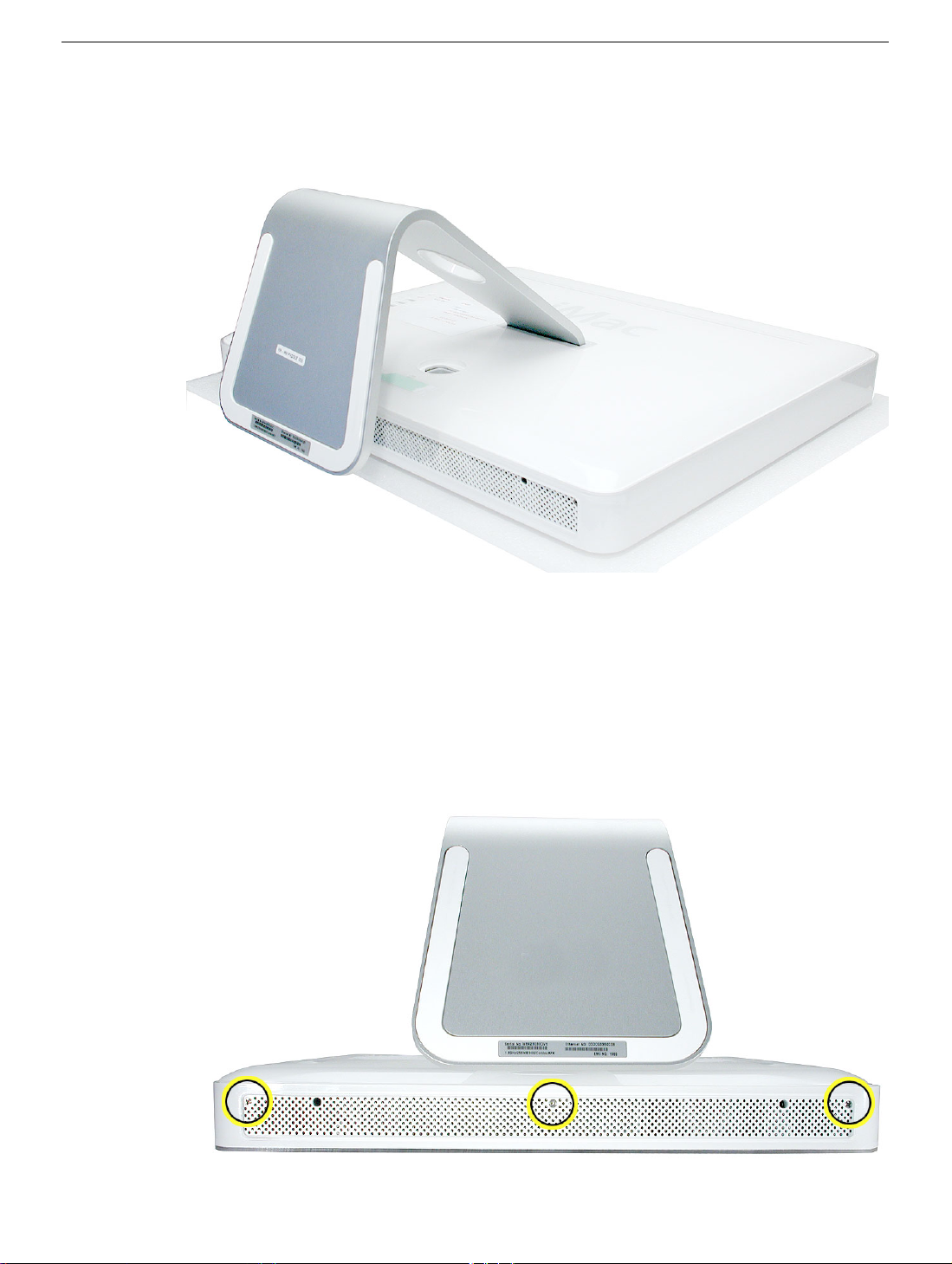
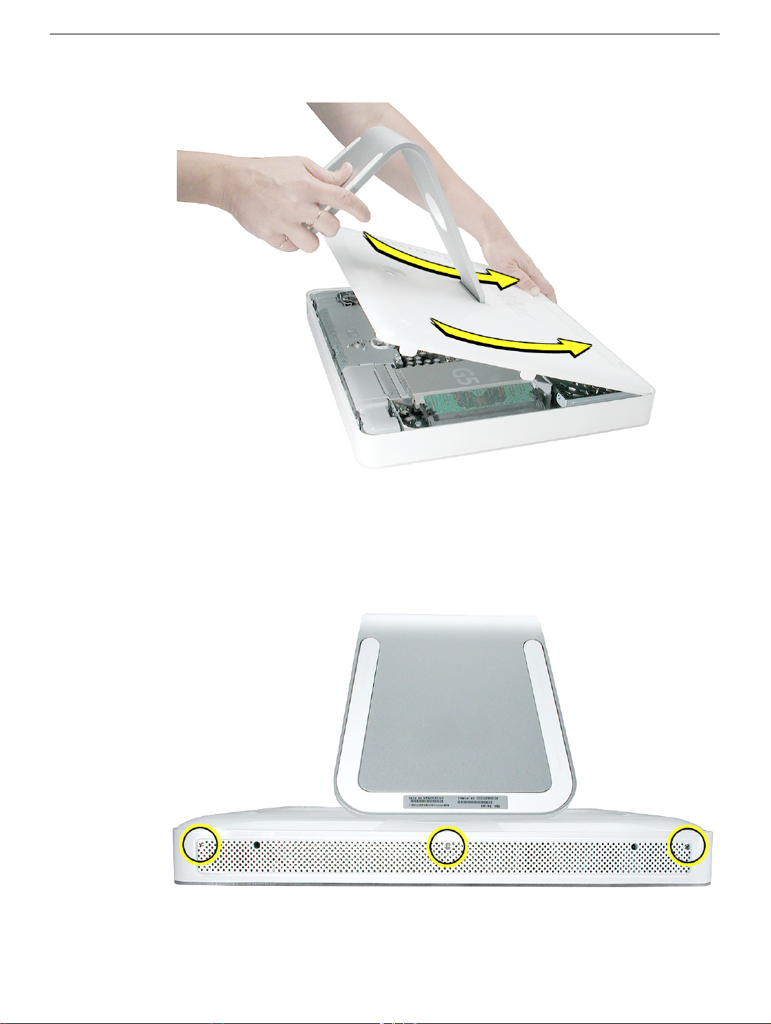
3. Place a soft, clean towel or cloth on the desk or surface. Hold the sides of the
computer and slowly lay the computer face down as shown.
4. Locate the three case screws circled below. You may have to lift the metal foot to
locate the middle case screw.
display/bezel assembly and cannot be removed.
5. Using the screwdriver provided, or a Phillips #2 screwdriver, loosen the three captive
screws.
once they stop turning.
Note:
Turn the screws to the left until they stop turning. Don’t force the screws
Note:
These screws are captive; they are part of the
6 -
iMac G5, 17-inch Take Apart
Removing the Back Cover
Page 9
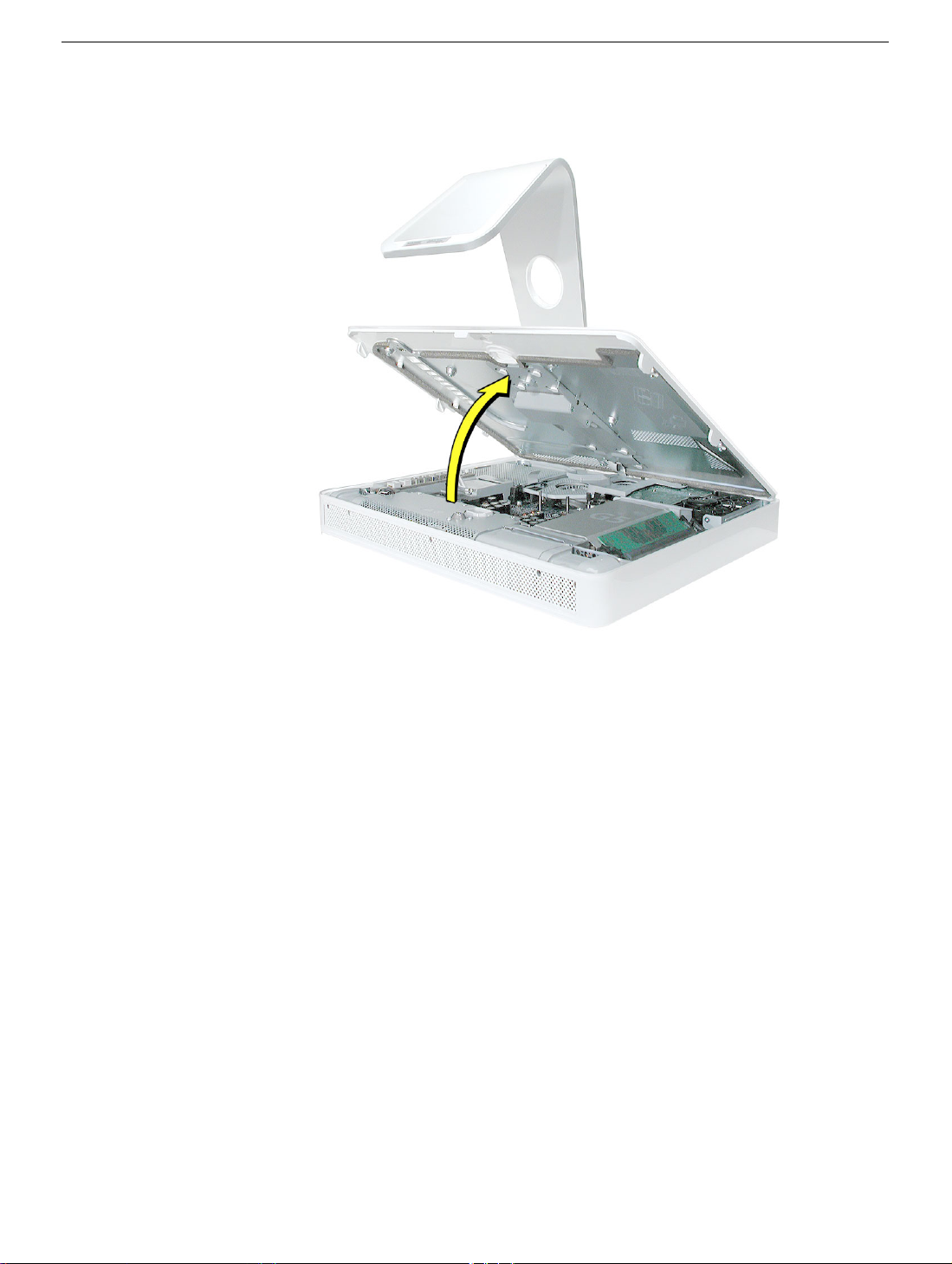
6. Holding the back cover by the metal stand, tilt the cover up and lift it off the computer.
Set the back cover aside.
Removing the Back Cover
iMac G5, 17-inch Take Apart -
7
Page 10
Replacing the Back Cover
Tools
Use the screwdriver provided, or a Phillips #2 screwdriver
Procedure
1. Remove the replacement back cover and foot from its packaging.
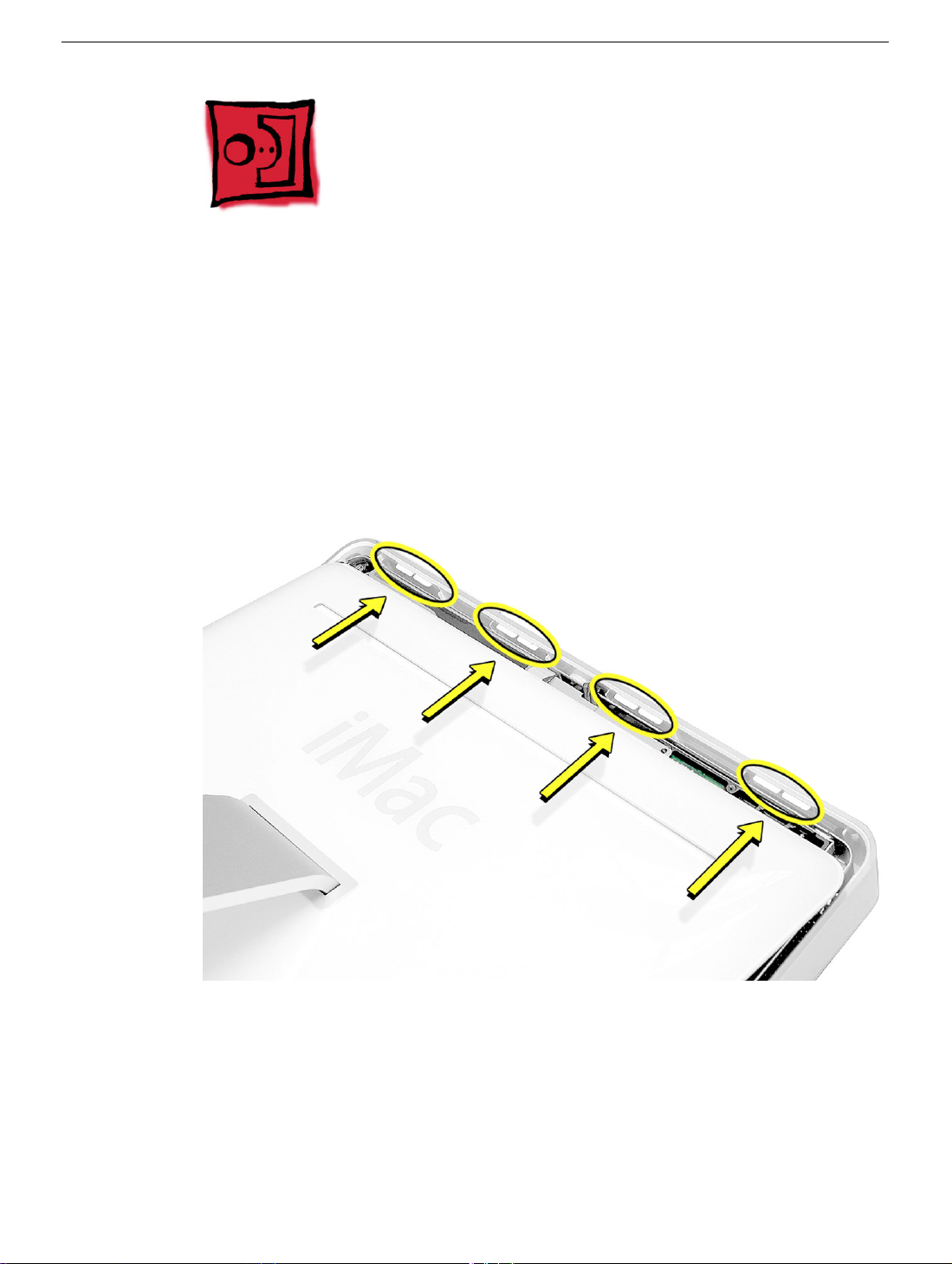
2. Replace the cover so that the slots on the top edge of the back cover mate with the
tabs on the display housing.
8 -
iMac G5, 17-inch Take Apart
Replacing the Back Cover
Page 11
3. Lower and press the cover into place until it fits snugly on the computer.
4. Tighten the three captive case screws by turning them to the right. Don’t overtighten
the screws
Replacing the Back Cover
iMac G5, 17-inch Take Apart -
9
Page 12
5. Make sure the case is not bowing along the bottom or sides. If it is, check that the
optical drive and cables are seated properly. There should be no gaps around the
edges when the screws are tightened.
6. Position the computer in the upright position. Reconnect the power cord and
remaining cables. Turn on the computer.
10 -
iMac G5, 17-inch Take Apart
Replacing the Back Cover
Page 13
Serial ATA Hard Drive
Tools
• Use the screwdriver provided, or a Phillips #2 screwdriver, preferably with a
magnetized tip
• Flatblade screwdriver
• Screw tray or something equivalent to hold the screws
Preliminary Steps
Before you begin, remove the back cover.
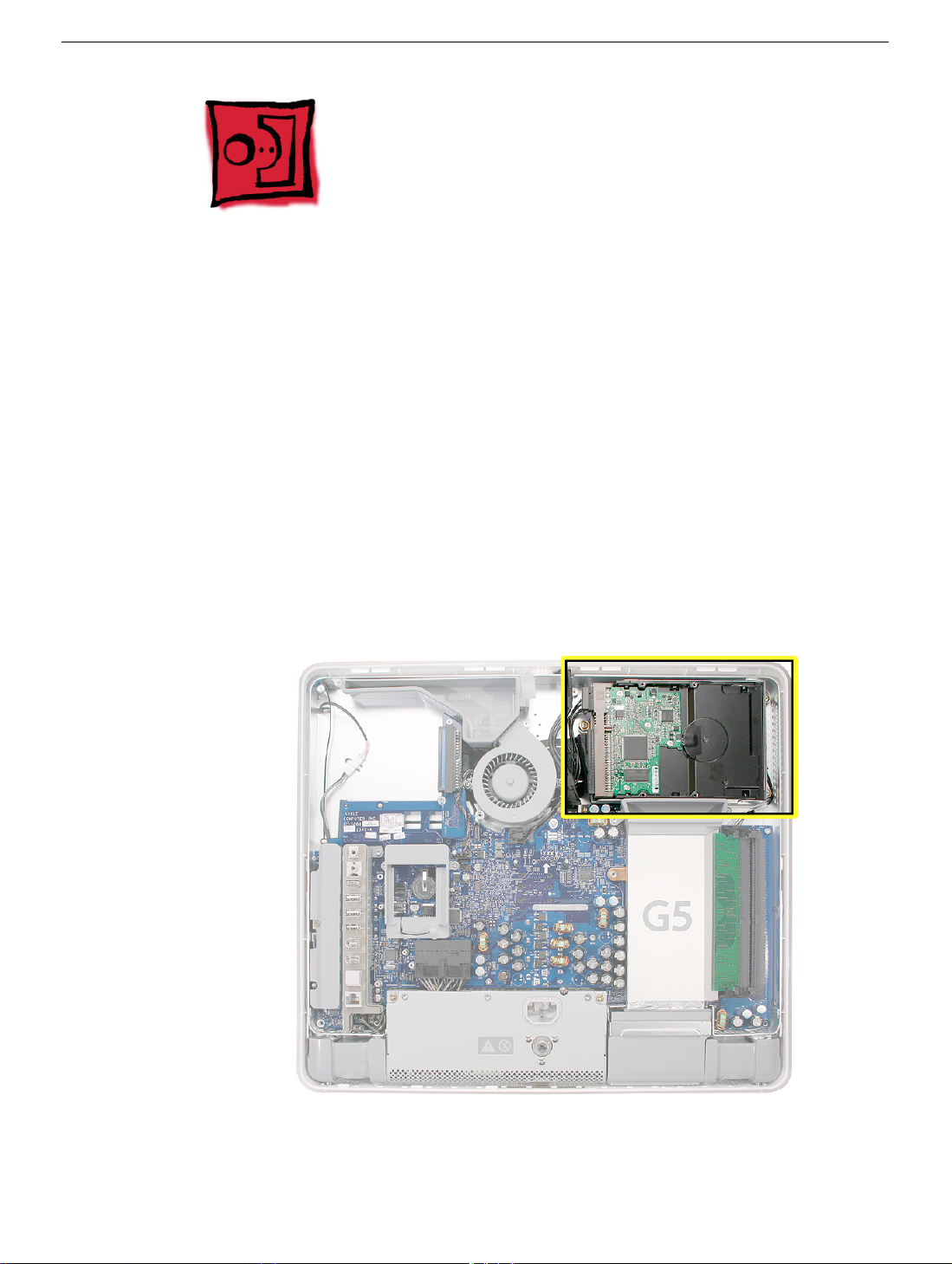
Part Location
Serial ATA Hard Drive
iMac G5, 17-inch Take Apart -
Page 14
Removing the Serial ATA Hard Drive
1. To access the hard drive you must first remove other service modules. This procedure
will show you how to remove and replace these modules.
module, set it aside, along with the screws for that module.
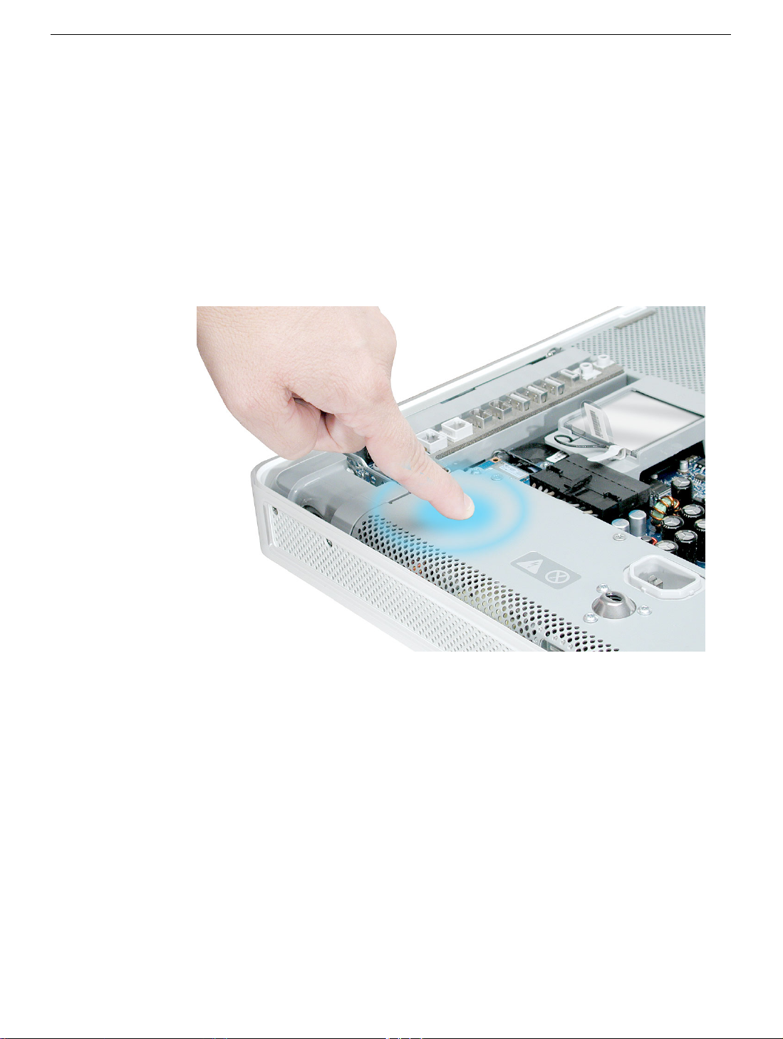
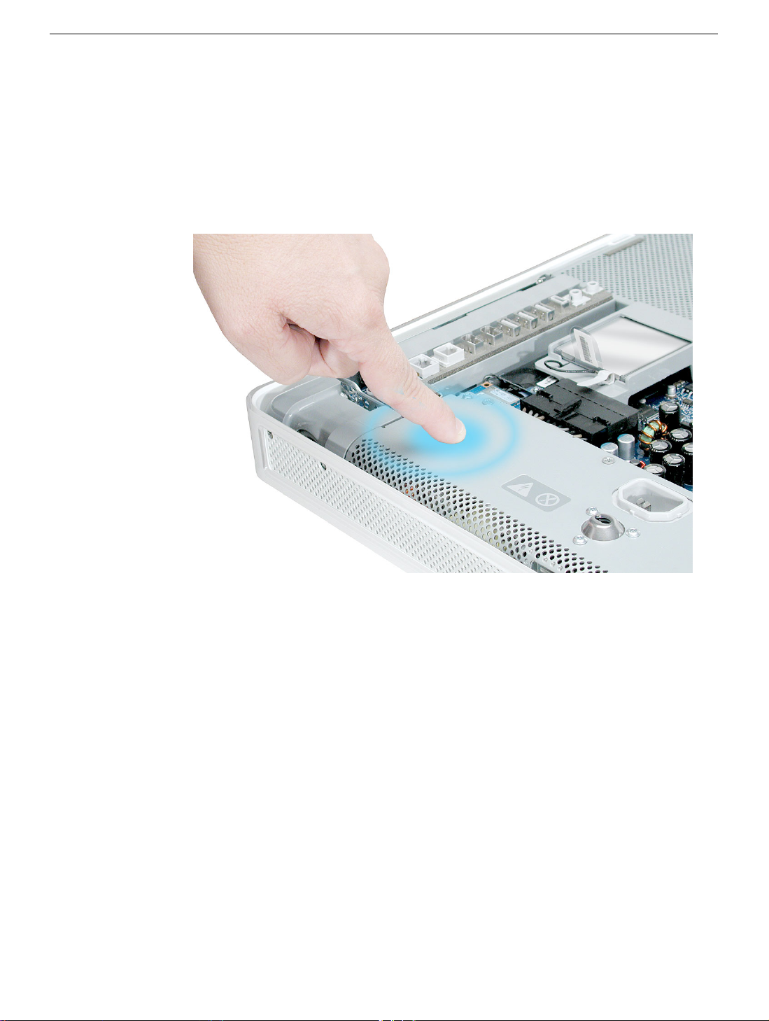
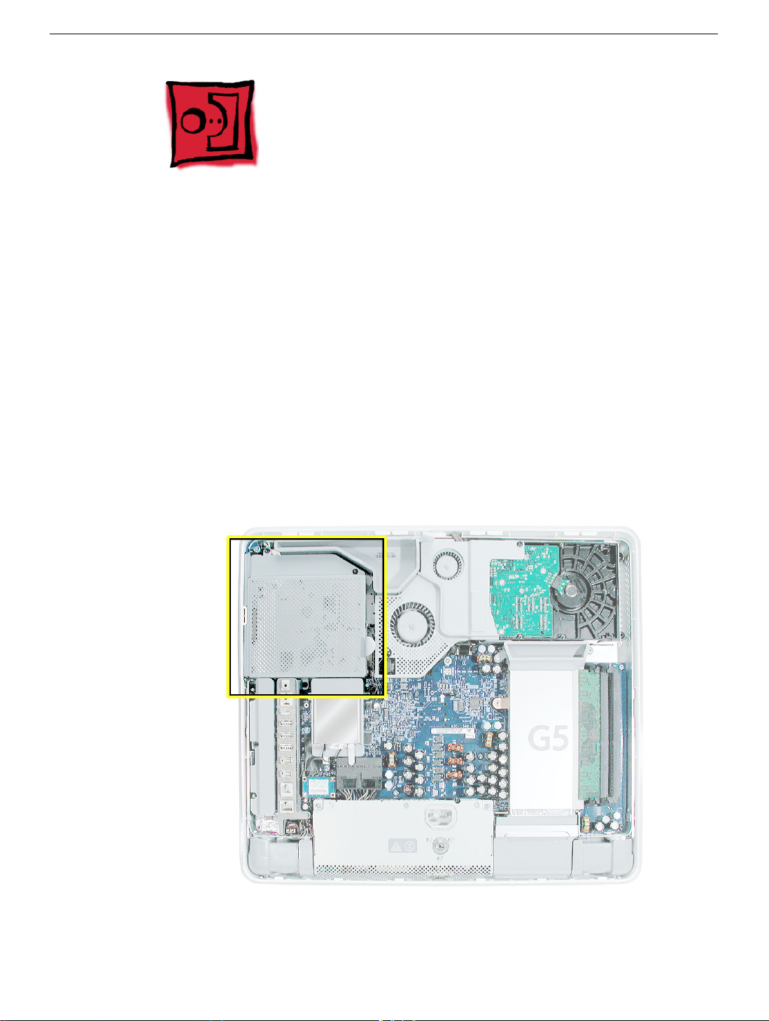
2. Ground yourself. Touch the metal surface (as shown below) on the inside of the
computer to discharge any static electricity.
Warning: Always discharge static electricity before you touch any parts or
install any components inside the computer. To avoid generating static
electricity, do not walk around the room until you have finished installing the
part and closed the computer
.
Note:
As you remove each
12 -
iMac G5, 17-inch Take Apart
Serial ATA Hard Drive
Page 15
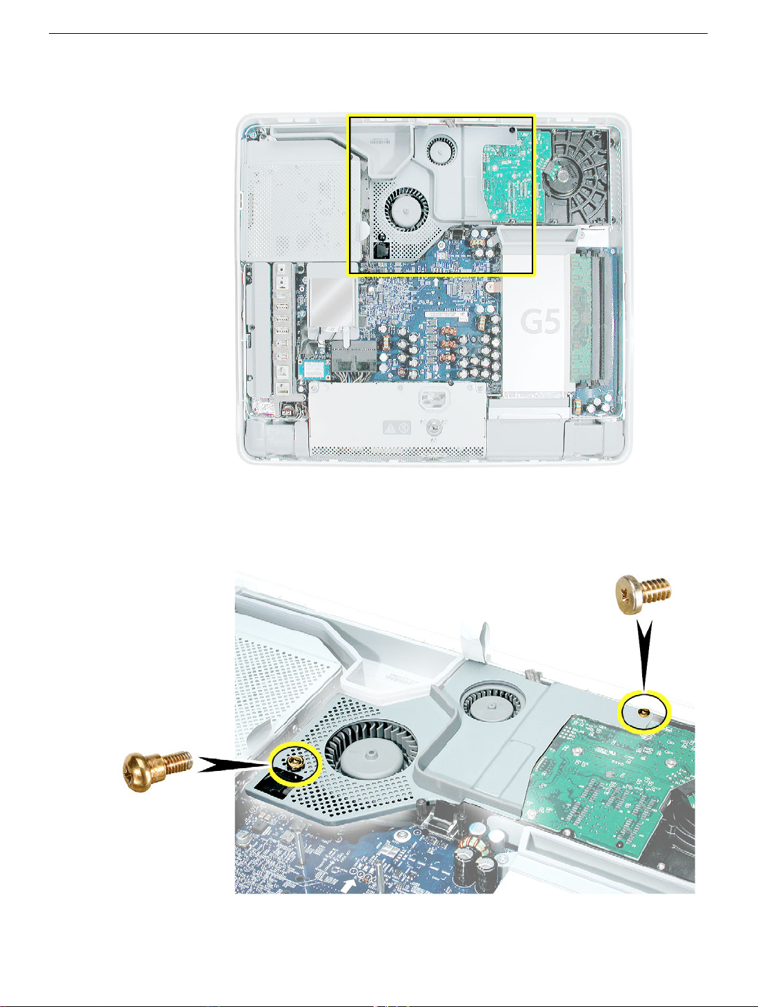
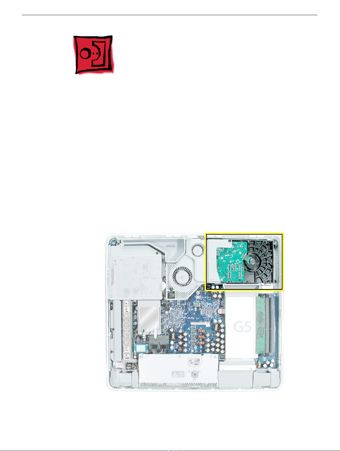
3. Locate the fan cover near the top of the computer.
4. Using the tool provided, or a Phillips #2 screwdriver, remove the two fan cover screws.
Lift the fan cover off the computer. Set the screws and fan cover aside.
Serial ATA Hard Drive
iMac G5, 17-inch Take Apart -
Page 16
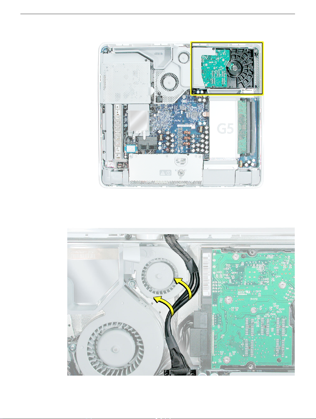
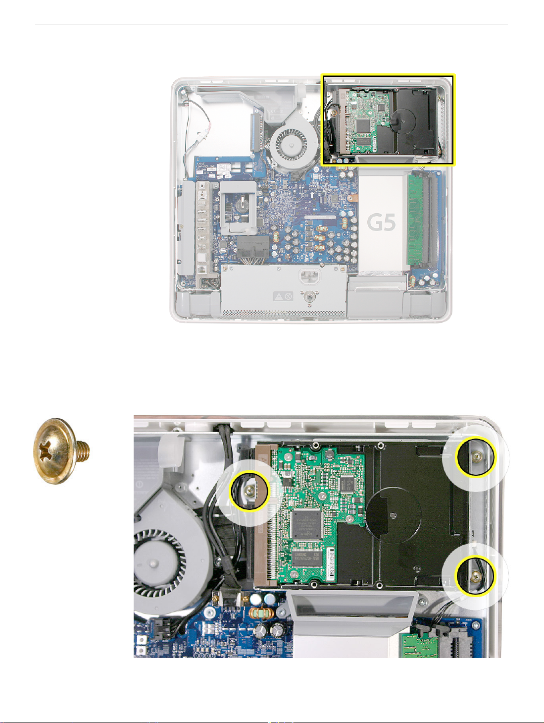
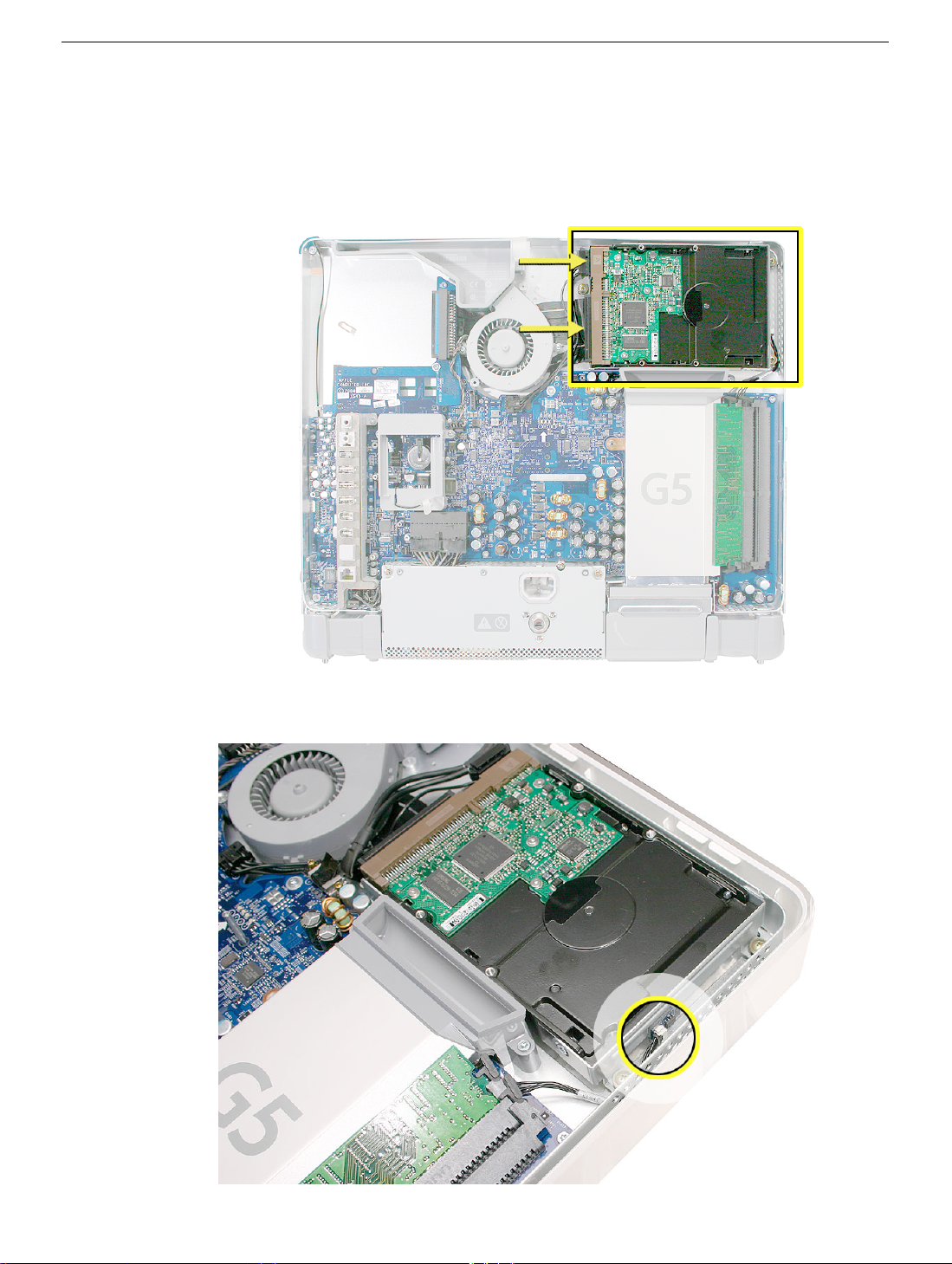
5. Locate the hard drive in the top right corner.
6. Move the black video cable (located to the left of the hard drive) out of the way to
access a hard drive screw.
14 -
iMac G5, 17-inch Take Apart
Serial ATA Hard Drive
Page 17
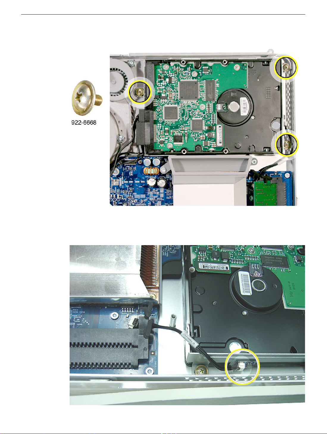
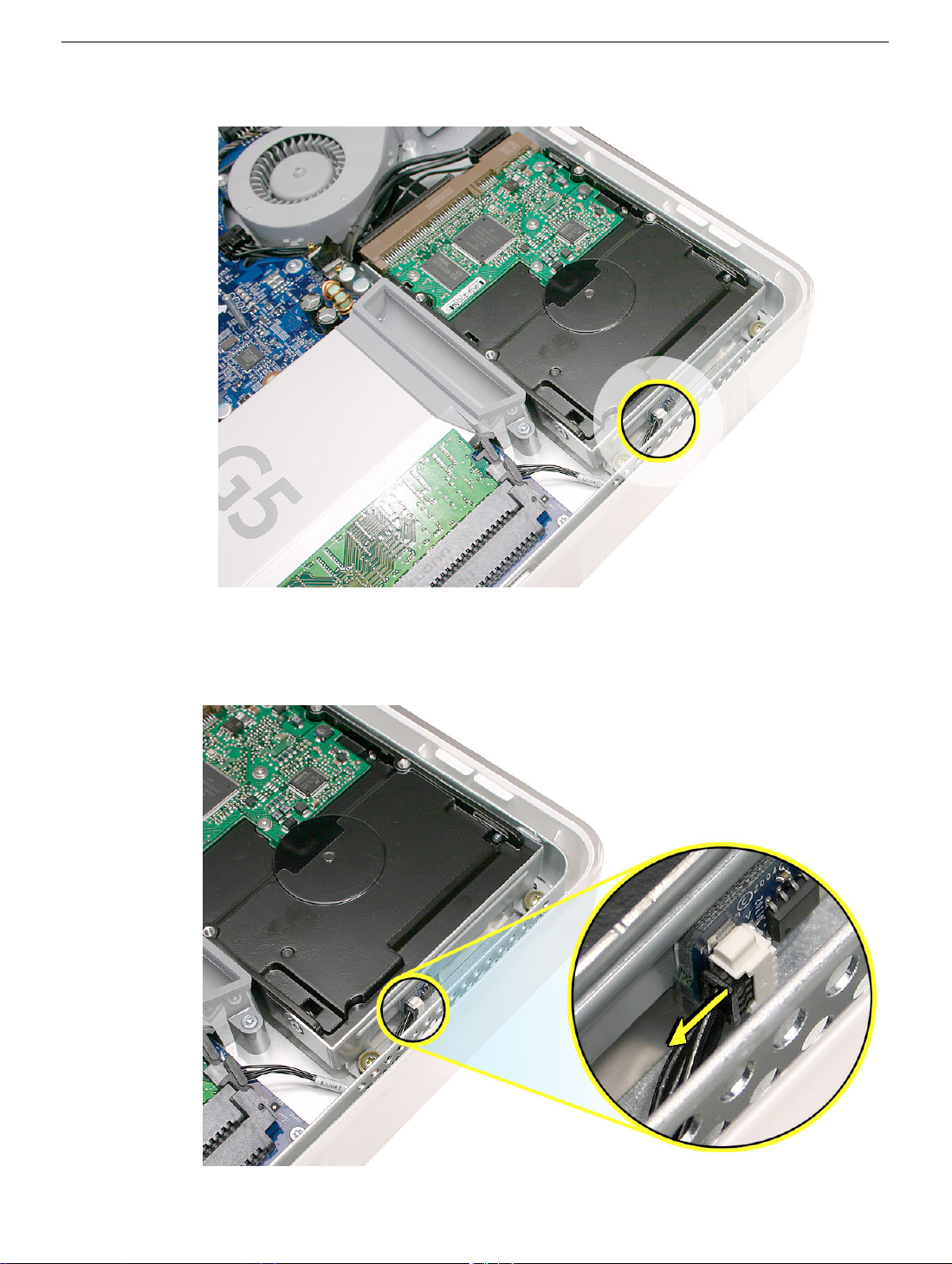
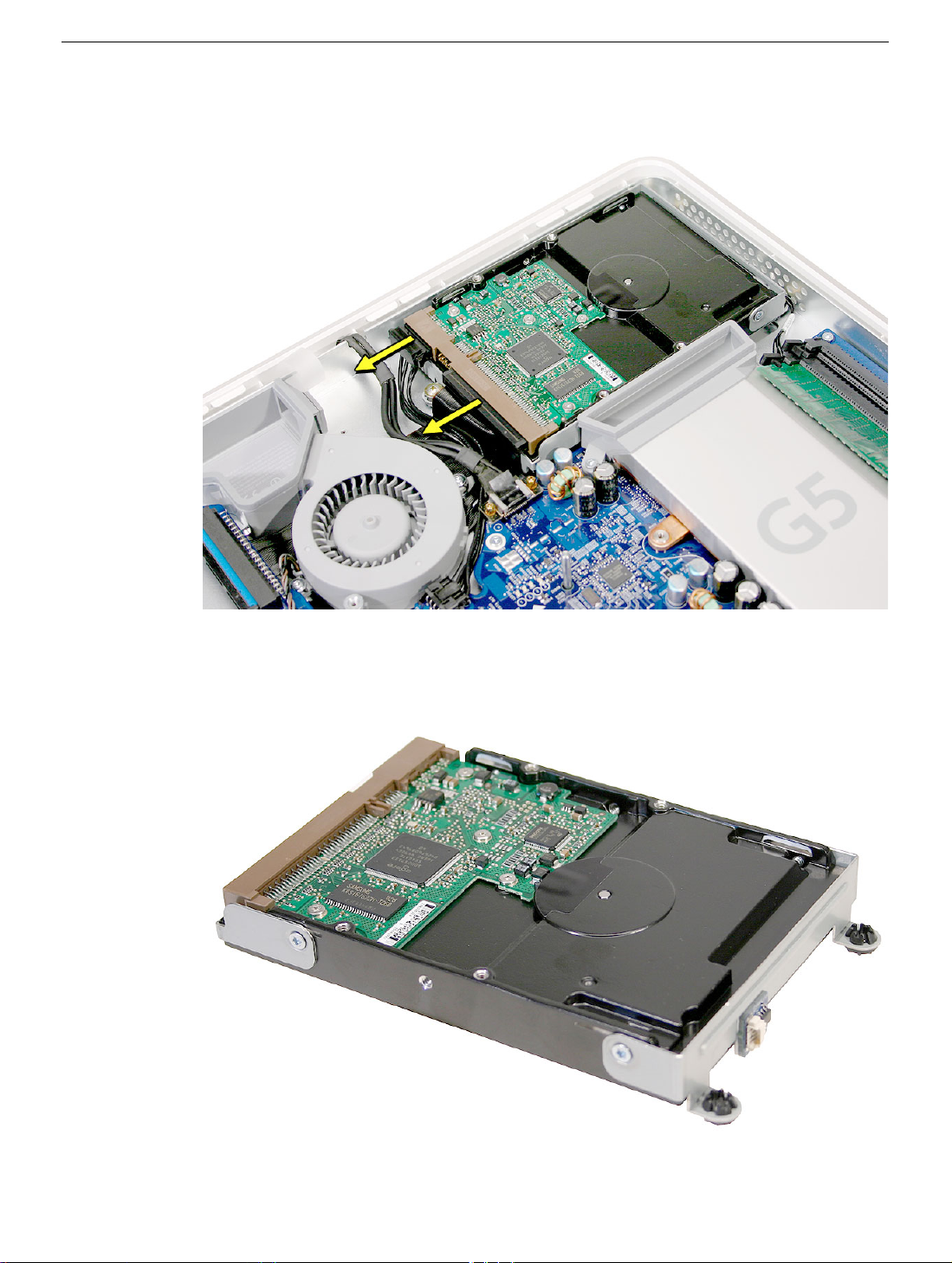
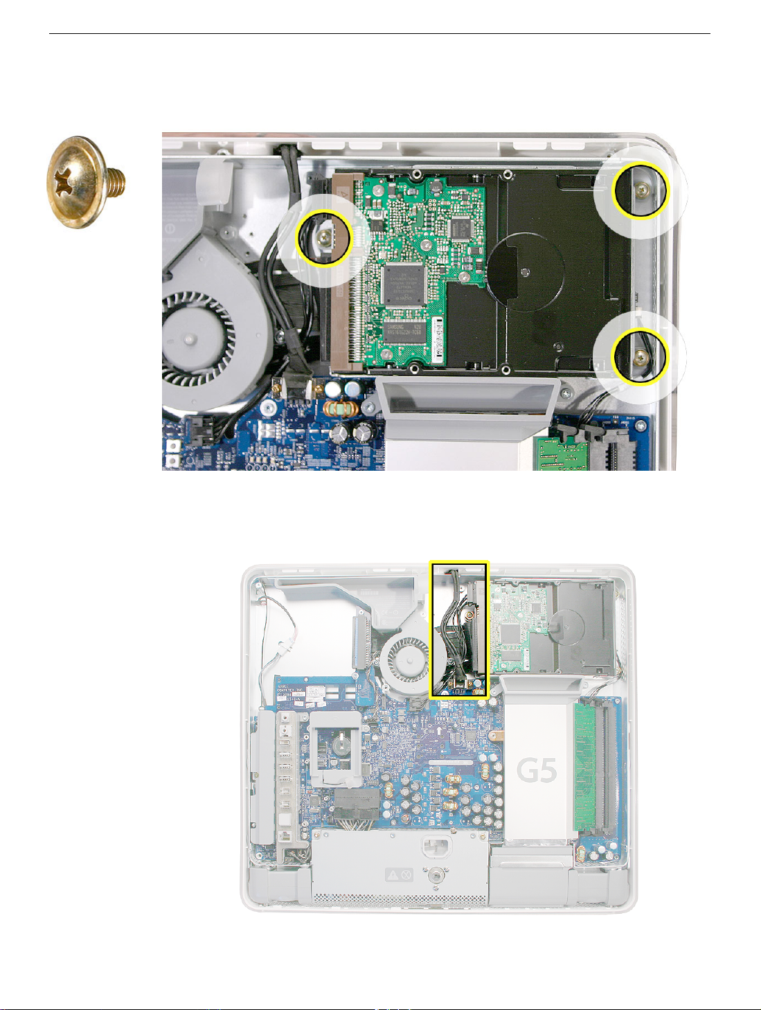
4. Remove the three hard drive screws. Set the screws aside.
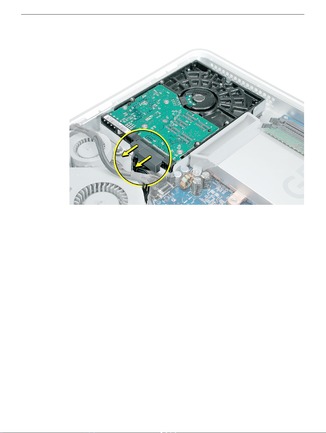
5. Carefully lift the hard drive straight up, about one inch, and disconnect the black cable
from the white connector on the hard drive.
attached to the logic board.
Note:
Leave the other end of the cable
Serial ATA Hard Drive
iMac G5, 17-inch Take Apart -
Page 18
6. Using your fingers, or a flat-blade screwdriver, disconnect the drive data cable and
power cable from the hard drive.
7. Lift the hard drive up and out of the midplane assembly.
drive to Apple in the packaging provided.
Important:
Return this hard
16 -
iMac G5, 17-inch Take Apart
Serial ATA Hard Drive
Page 19
Replacing the Serial ATA Hard Drive
1. Remove the replacement hard drive from its packaging.
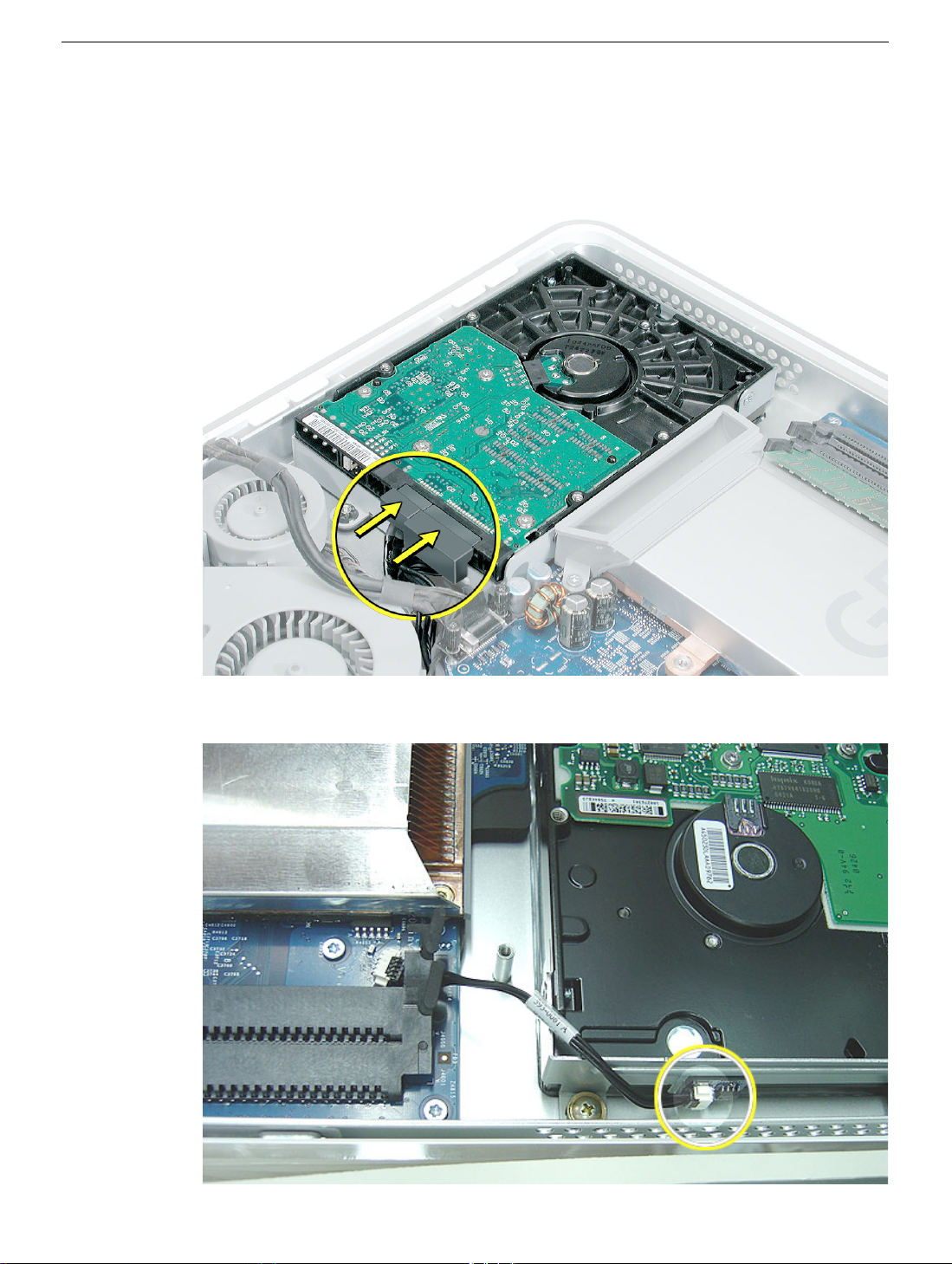
2. Connect the drive data cable and power cable to the hard drive. Lower the hard drive
into place on the midplane.
3. Connect the black cable to the white connector on end of the hard drive.
Serial ATA Hard Drive
iMac G5, 17-inch Take Apart -
Page 20
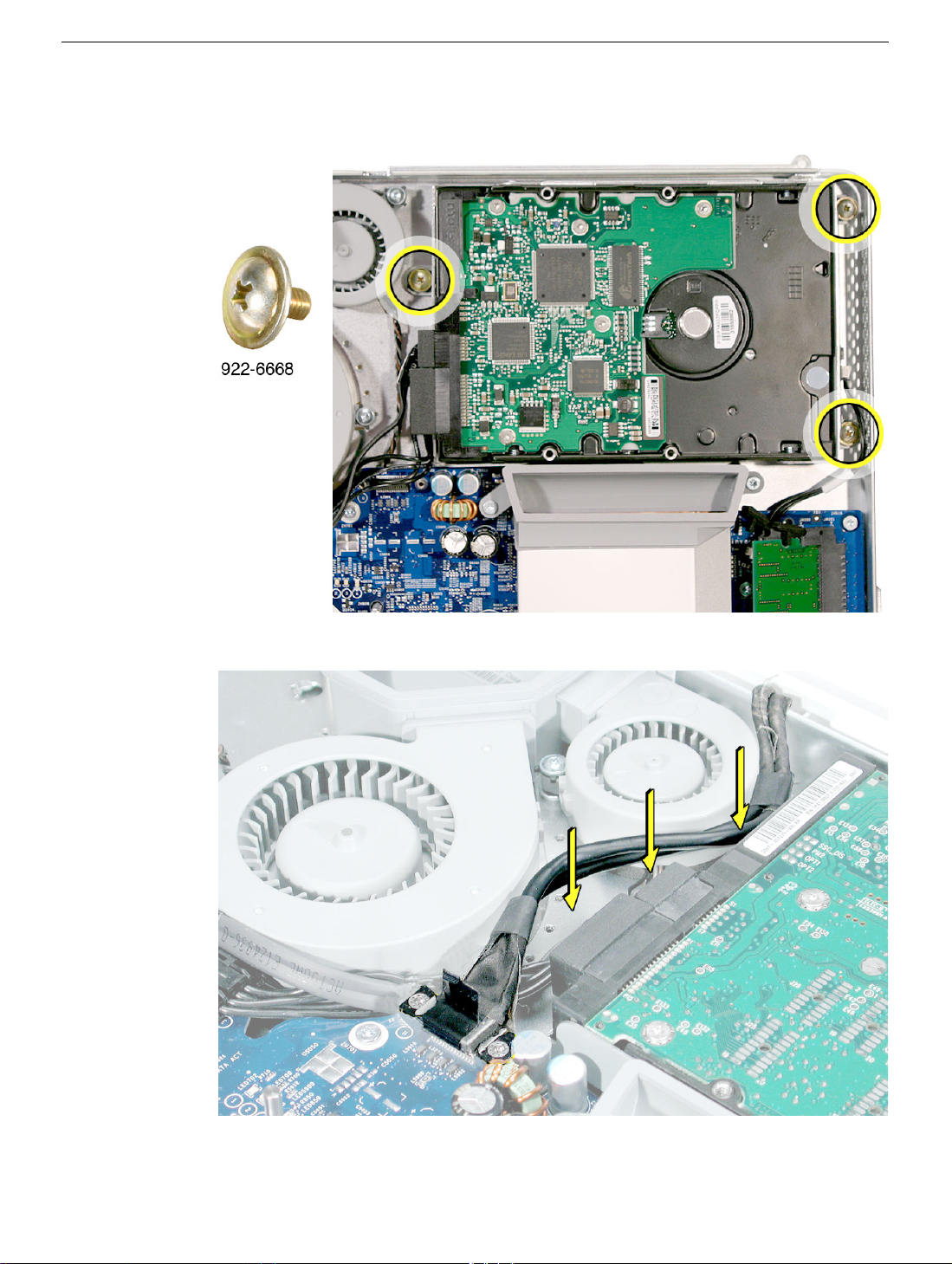
4. Replace the three hard drive screws.
5. Tuck the black video cable into the area shown by the arrows.
18 -
iMac G5, 17-inch Take Apart
Serial ATA Hard Drive
Page 21
6. Press the video cable into the notch on the midplane chassis.
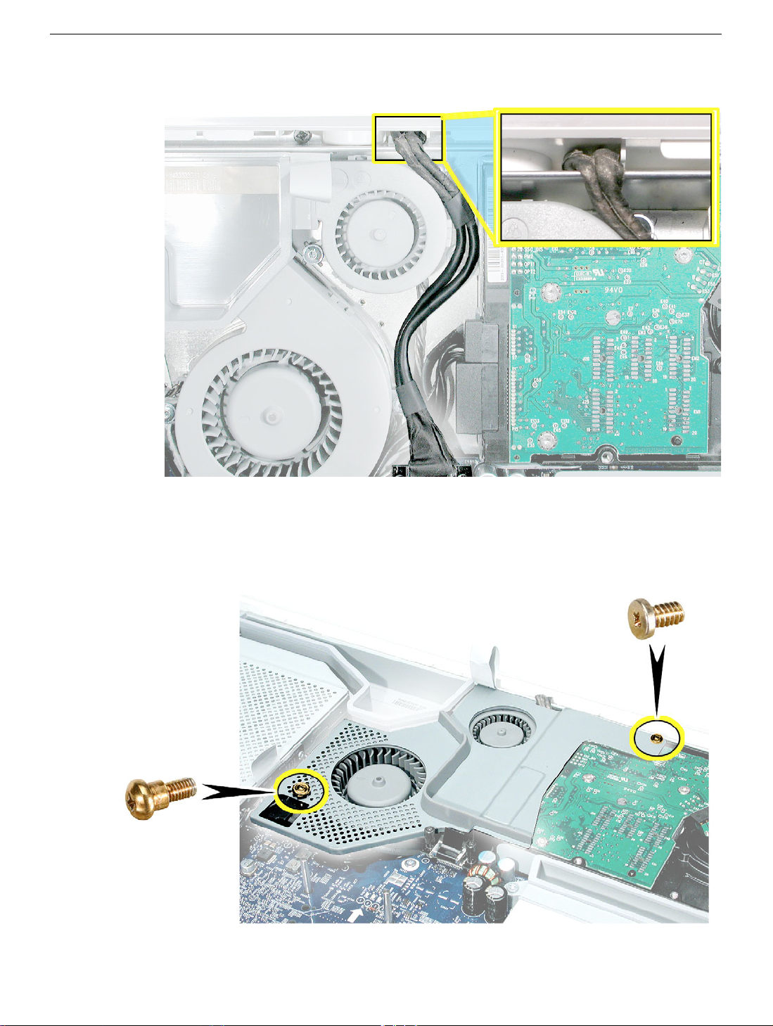
4. Replace the two fan cover screws. The larger screw attaches on the left.
sure the pull tab is sticking up as shown
Note:
Make
Serial ATA Hard Drive
iMac G5, 17-inch Take Apart -
Page 22
Parallel ATA Hard Drive
Tools
• Use the screwdriver provided, or a Phillips #2 screwdriver, preferably with a
magnetized tip
• Screw tray or something equivalent to hold the screws
Preliminary Steps
Before you begin, remove the back cover.
Part Location
Note:
The Parallel ATA hard drive is only available on the Education model.
20 -
iMac G5, 17-inch Take Apart
Parallel ATA Hard Drive
Page 23
Removing the Parallel ATA Hard Drive
1. Ground yourself. Touch the metal surface (as shown below) on the inside of the
computer to discharge any static electricity.
Warning: Always discharge static electricity before you touch any parts or
install any components inside the computer. To avoid generating static
electricity, do not walk around the room until you have finished installing the
part and closed the computer
.
Parallel ATA Hard Drive
iMac G5, 17-inch Take Apart -
Page 24
2. Locate the parallel ATA hard drive in the top right corner.
4. Remove the three hard drive screws. Set the screws aside.
22 -
iMac G5, 17-inch Take Apart
Parallel ATA Hard Drive
Page 25
5. Locate the white connector on the end of the hard drive.
6. Carefully lift the hard drive straight up, about one inch and disconnect the black cable
from the white connector.
board.
Note:
Leave the other end of the cable attached to the logic
Parallel ATA Hard Drive
iMac G5, 17-inch Take Apart -
Page 26
7. Using your fingers, disconnect the drive data cable and power cable from the hard
drive.
8. Lift the hard drive up and out of the midplane assembly.
drive with the carrier to Apple in the packaging provided.
Important:
Return this hard
24 -
iMac G5, 17-inch Take Apart
Parallel ATA Hard Drive
Page 27
Replacing the Parallel ATA Hard Drive
1. Remove the replacement hard drive from its packaging.
2. Connect the drive data cable and power cable to the hard drive. Lower the hard drive
into place on the midplane.
3. Connect the black cable to the white connector on end of the hard drive.
Parallel ATA Hard Drive
iMac G5, 17-inch Take Apart -
Page 28
4. Replace the three hard drive screws.
.
5. Before replacing the back cover, tuck the black video cable into the space next to the
hard drive.
26 -
iMac G5, 17-inch Take Apart
Parallel ATA Hard Drive
Page 29
Optical Drive
Tools
• Use the screwdriver provided, or a Phillips #2 screwdriver, preferably with a
magnetized tip
• Screw tray or equivalent to hold the screws
Preliminary Steps
Before you begin, remove the back cover.
Part Location
Note:
The education models do not have an optical drive.
Optical Drive
iMac G5, 17-inch Take Apart -
Page 30
Removing the Optical Drive
1. Ground yourself. Touch the metal surface (as shown below) on the inside of the
computer to discharge any static electricity.
Warning: Always discharge static electricity before you touch any parts or
install any components inside the computer. To avoid generating static
electricity, do not walk around the room until you have finished installing the
part and closed the computer
.
28 -
iMac G5, 17-inch Take Apart
Optical Drive
Page 31

2. Locate the optical drive in the top left corner.
4. Using a Phillips #2 screwdriver, remove the three optical drive screws circled below.
Set the screws aside.
Optical Drive
iMac G5, 17-inch Take Apart -
Page 32

5. Pull the optical drive tab straight up and then to the right. Set the optical drive aside.
30 -
iMac G5, 17-inch Take Apart
Optical Drive
Page 33

Replacing the Optical Drive
1.
Note:
A microfoam shim is included with the replacement optical drive and should be
installed using the instructions included below. The microfoam shim will prevent optical
media from ejecting out of the system and dropping to the desktop. Only one
microfoam insert should be used per system. The shim part number is 922-7671.
2. Locate the enclosed piece of white microfoam and the two white posts (circled) on the
bezel.
3. With the shiny side of the microfoam facing the bezel, slide the holes of the microfoam
onto the two white posts on the bezel.
Optical Drive
iMac G5, 17-inch Take Apart -
Page 34

4. Tuck the mircofoam into place before installing the optical drive.
5. Remove the replacement optical drive from its packaging.
6. Replace the optical drive in the direction of the arrow, lining up the white posts on the
bezel with the holes on the optical drive bezel.
32 -
iMac G5, 17-inch Take Apart
Optical Drive
Page 35

7. The optical drive will
the optical drive is not seated accurately, the optical drive may not function.
click
into place when you push down near the pull tab.
Note:
If
8. Make sure no microfoam is sticking out of the bezel.
computer, partially insert an optical disc to make sure it inserts smoothly.
Note:
Before reassembling the
Optical Drive
iMac G5, 17-inch Take Apart -
Page 36

9. Replace the three optical drive screws.
34 -
iMac G5, 17-inch Take Apart
Optical Drive
Page 37

Microfoam Shim
Tools Required
• Use the screwdriver provided, or a Phillips #2 screwdriver, preferably with a
magnetized tip
• Screw tray or equivalent to hold the screws
Preliminary Steps
Before you begin, remove the back cover and the optical drive.
Part Location
Note:
The education models do not have an optical drive.
Microfoam Shim
iMac G5, 17-inch Take Apart -
Page 38

Installing the Microfoam onto the Bezel
1. Steps 2-7 show photos of the microfoam inside the iMac G5 20-inch computer. The
installation procedure is the same for the 17-inch computer. Go on to the next step.
2. Locate the piece of microfoam and the two white posts (circled) on the bezel.
3. With the shiny side of the microfoam facing the bezel, slide the holes of the microfoam
onto the two white posts on the bezel.
36 - iMac G5, 17-inch Take Apart
Microfoam Shim
Page 39

4. Tuck the mircofoam into place before installing the optical drive.
5. Replace the optical drive in the direction of the arrow, lining up the white posts on the
bezel with the holes on the optical drive bezel.
Microfoam Shim
iMac G5, 17-inch Take Apart -
Page 40

6. Slide the optical drive into place and press down near the tab to reconnect the drive.
7. Make sure no microfoam is sticking out of the bezel. Note: Before reassembling the
computer, partially insert an optical disc to make sure it inserts smoothly.
8. Replace the optical drive screws.
9. Replace the back cover.
38 - iMac G5, 17-inch Take Apart
Microfoam Shim
Page 41

Fan Cover
Tools Required
• Use the screwdriver provided, and a Phillips #2 screwdriver, preferably with a
magnetized tip
• Screw tray or equivalent to hold the screws
Preliminary Steps
Before you begin, remove the back cover.
Part Location
Note: This fan cover is not present on the education model.
.
Fan Cover
iMac G5, 17-inch Take Apart -
Page 42

Removing the Fan Cover
1. Ground yourself. Touch the metal surface (as shown below) on the inside of the
computer to discharge any static electricity.
Warning: Always discharge static electricity before you touch any parts or
install any components inside the computer. To avoid generating static
electricity, do not walk around the room until you have finished installing the
part and closed the computer.
40 - iMac G5, 17-inch Take Apart
Fan Cover
Page 43

2. Locate the fan cover shown below.
4. Using a Phillips #2 for the screw on the left and a Phillips #2 for the screw on the right,
remove the two screws. Lift the fan cover off the midplane and set the fan cover aside.
Fan Cover
iMac G5, 17-inch Take Apart -
Page 44

Replacing the Fan Cover
1. Remove the replacement fan cover from its packaging.
4. Replace the two fan cover screws. The larger screw attaches on the left. Note: Make
sure the pull tab is sticking up as shown.
42 - iMac G5, 17-inch Take Apart
Fan Cover
Page 45

Fans, Upper
Tools Required
• Phillips #2 screwdriver or Torx-8 (some models have torx screws on the fan)
• Screw tray or equivalent to hold the screws
Preliminary Steps
Before you begin, remove the back cover and the fan cover.
Part Location
Fans, Upper
iMac G5, 17-inch Take Apart -
Page 46

Removing the Fans
1. Depending on the type of screws present (Torx 8 or Phillips #2), loosen the two fan
screws. Note: You don’t have to remove the screws from the rubber grommets to
remove the fan, just loosen the screws.
2. Disconnect the fan cable from the connector on the logic board. Pull on the black
connector, not on the cable. Route the fan cable under the black cable (as shown).
44 - iMac G5, 17-inch Take Apart
Fans, Upper
Page 47

3. Lift the fan out of the computer.
4. If your are replacing the fan, remove the screws from the fan grommets. Using a
screwdriver, push the fan screws out of the grommets and set them aside. Use these
screws on the replacement fan.
5. Go on to the next step to remove the second fan.
Fans, Upper
iMac G5, 17-inch Take Apart -
Page 48

6. Move the video cable to the left to access the fan screw near the top of the computer
7. Depending on the type of screws present (Torx 8 or Phillips #2), loosen the two fan
screws. Note: You don’t have to remove the screws from the rubber grommets to
remove the fan, just loosen the screws
46 - iMac G5, 17-inch Take Apart
Fans, Upper
Page 49

8. Lift the fan out of the computer and disconnect the fan cable from the connector on the
logic board. Pull on the black connector, not on the cable.
9. If you are replacing the fan, remove the screws from the fan grommets. Using a
screwdriver, push the fan screws out of the grommets and set them aside.
Fans, Upper
iMac G5, 17-inch Take Apart -
Page 50

Replacing the Fans
1. Route the fan cable under the black hard drive cable. Connect the fan cable to the
connector on the logic board. Note: The fan cables are keyed.
2. Place the two screws into the grommets on the replacement fan. Position the fan into
place and tighten the two fan screws.
48 - iMac G5, 17-inch Take Apart
Fans, Upper
Page 51

3. Tuck the video cable into the space between the fan and the hard drive.
4. Lower the larger fan into the chassis, lining up the screws with the screw holes.
Caution: Move the fan cable (from the smaller fan) out from under the larger fan as
you lower the fan into the chassis. Tighten the two fan screws.
Fans, Upper
iMac G5, 17-inch Take Apart -
Page 52

5. Route the fan cable under the black cable. Connect the fan cable to the logic board.
6. Replace the two fan cover screws. The larger screw attaches on the left. Note: Make
sure the pull tab at the top of the case is sticking up as shown.
7. Replace the back cover.
50 - iMac G5, 17-inch Take Apart
Fans, Upper
Page 53

Inverter
Tools Required
• Phillips #2 screwdriver, preferably with a magnetized tip
• Screw tray or something equivalent to hold the screws
Preliminary Steps
Before you begin, remove the back cover.
Part Location
Inverter
iMac G5, 17-inch Take Apart -
Page 54

Removing the Inverter
1. To access the inverter assembly other service modules have to be removed. This
procedure will show you how to remove and replace each module. As you remove
each module, set it aside, along with the screws for that module.
2. Important: Ground yourself. Touch the metal surface (as shown below) on the inside
of the computer to discharge any static electricity.
Warning: Always discharge static electricity before you touch any parts or install any
components inside the computer. To avoid generating static electricity, do not walk
around the room until you have finished installing the part and closed the computer.
52 - iMac G5, 17-inch Take Apart
Inverter
Page 55

3. Locate the optical drive.
4. Using a Phillips #2 screwdriver, remove the three optical drive screws.
Inverter
iMac G5, 17-inch Take Apart -
Page 56

5. Pull the optical drive tab straight up and then to the right. Set the optical drive aside.
6. Locate the inverter-to-display panel cable connector.
54 - iMac G5, 17-inch Take Apart
Inverter
Page 57

7. Release the cable from the clip. Disconnect the cable connector.
4. Using the iMac G5 screw tool, or a Phillips #2 screwdriver, remove the inverter screw.
Inverter
iMac G5, 17-inch Take Apart -
Page 58

5. Lift the inverter straight up to disconnect the inverter board.
6. Disconnect the white connector (circled below) by pulling it straight up. Lift the inverter
out of the computer.
56 - iMac G5, 17-inch Take Apart
Inverter
Page 59

7. Turn over the inverter as shown. Using your fingers or a flat-blade screwdriver,
carefully remove the gray plastic inverter cover by gently prying the tabs (circled
below) away from the board. Set the plastic cover aside.
8. This cover will be attached to the replacement inverter board.
Inverter
iMac G5, 17-inch Take Apart -
Page 60

9. Return the inverter board to Apple in the packaging provided.
58 - iMac G5, 17-inch Take Apart
Inverter
Page 61

Replacing the Inverter
1. Remove the replacement inverter from its packaging.
2. Locate the gray plastic cover you set aside.
Inverter
iMac G5, 17-inch Take Apart -
Page 62

3. Install the plastic cover on the replacement inverter board. Gently squeeze the board
near each tab (circled) until all five tabs snap onto the board.
4. Connect the white connector on the inverter board to the midplane board. The
connector is keyed, which means it can connect only one way. Route this cable around
the silver post (to the right of the cable). Important: If the connector is not inserted
correctly there will be no video on the display.
60 - iMac G5, 17-inch Take Apart
Inverter
Page 63

5. As you lower the inverter into place, connect the black connector to the pins on the
board. Use the tall silver pins as a guide to align the inverter. Important: Make sure
the connector mates with the pins. Double check that it’s connected.
6. Replace the inverter screw.
Inverter
iMac G5, 17-inch Take Apart -
Page 64

4. Reconnect the inverter-to-display panel cable. Important: The connector is keyed (it
fits together only one way)
5. Secure the connector under the metal tab.
62 - iMac G5, 17-inch Take Apart
Inverter
Page 65

6. Locate the optical drive that you set aside. Holding the optical drive by the back end
(near the tab), insert the drive at an angle to mate the two white pins and the plastic
rectangle with the two holes and notch on the optical drive.
7. With your thumb on the tab and your index finger behind the tab, push the drive
forward and down. The optical drive should click into its connector. Note: If the optical
drive won’t click into place, check that the fan cables are not obstructing the optical
drive connector.
Inverter
iMac G5, 17-inch Take Apart -
Page 66

8. Replace the optical drive screws.
64 - iMac G5, 17-inch Take Apart
Inverter
Page 67

Memory (DIMMs)
About iMac G5 Memory
• iMac G5 computers work with memory modules (DIMMs) that meet all of these criteria:
PC3200, 2.5V, unbuffered, 8-byte, nonparity, 184-pin, 400Mhz DDR SDRAM.
• There are two RAM slots. The maximum amount of RAM you can install is 2 GB. You
can use RAM module sizes of 256 MB, 512 MB and 1 GB, in either slot.
• DIMMs with any of the following features are not supported in the iMac G5 computer:
registers or buffers, PLLs, ECC, parity, or EDO RAM
Tools
Use the screwdriver provided, or a Phillips #2 screwdriver to open the back co
Preliminary Steps
Before you begin, remove the back cover.
Memory (DIMMs)
Part Location
iMac G5, 17-inch Take Apart -
Page 68

Removing the Memory
Important: Ground yourself. Touch the metal surface (as shown below) on the inside
of the computer to discharge any static electricity.
Warning: Always discharge static electricity before you touch any parts or
install any components inside the computer. To avoid generating static
1.
electricity, do not walk around the room until you have finished installing the
part and closed the computer.
66 - iMac G5, 17-inch Take Apart
Memory (DIMMs)
Page 69

2. Locate the memory module(s) in the bottom right corner.
3. Rotate the computer to the left so the memory is in the position shown below.
4. To release the memory from its slot, push down on the two side latches. Then pull the
memory module out of the slot. Repeat this step if you have a second memory
module. Important: Return the memory to Apple in the packaging provided.
Memory (DIMMs)
iMac G5, 17-inch Take Apart -
Page 70

Replacing the Memory
1. Remove the replacement memory module from its packaging.
2. Replace the memory module(s) by lining up the notch on the module with the notch on
the slot.
3. Press firmly on the memory module until it clicks into place. Use your thumb and index
finger to push the module into the slot.
68 - iMac G5, 17-inch Take Apart
Memory (DIMMs)
Page 71

Power Supply
Tools Required
• Use the screwdriver provided, or a Phillips #2 screwdriver, preferably with a
magnetized tip
• Flat-blade screwdriver
• Screw tray or equivalent to hold the screws
Preliminary Steps
Before you begin, remove the back cover.
Part Location
Power Supply
iMac G5, 17-inch Take Apart -
Page 72

Important Things to Know
Note: These instructions cover the iMac G5 (17-inch) models. The models may look
slightly different from one shown in the illustration; however, the following
procedure applies to both models.
1. The replacement power supply has an ambient light sensor attached with two plastic
rivets. If your computer doesn’t have an ambient light sensor (see next step), remove
the ambient light sensor from the replacement power supply.
2. How do you tell if you have an iMac G5 with the ambient light sensor? Look at the
picture below. Along the bottom of the display bezel, next to the middle case screw is
a small bump protruding from the case. This is the ambient light sensor.
3. All customer removable screws are brass colored . Do not remove screws unless
they are brass colored, or you will void your warranty.
4. Ground yourself when working on the computer. The procedure will show you how to
ground yourself.
5. Do not pull on individual wires when disconnecting a part; pull on the connector.
6. A magnetized “L”-shaped Phillips screwdriver is included with the replacement part.
70 - iMac G5, 17-inch Take Apart
Power Supply
Page 73

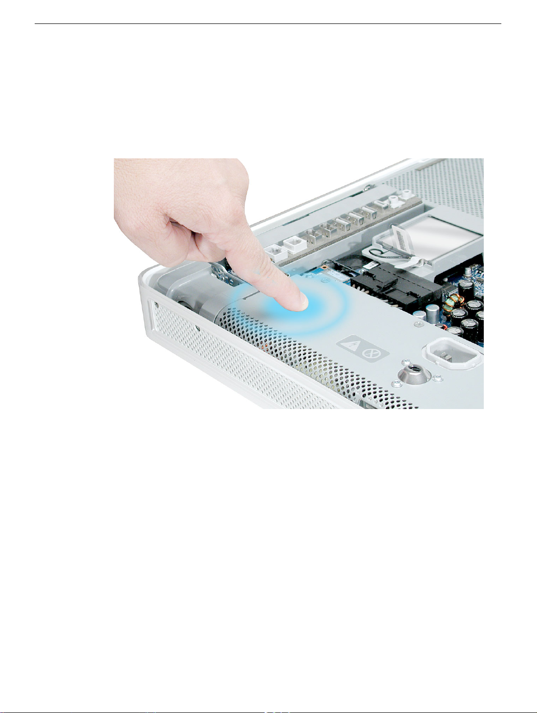
Removing the Power Supply
1. Ground yourself. Touch the metal surface (as shown below) on the inside of the
computer to discharge any static electricity.
Warning: Always discharge static electricity before you touch any parts or
install any components inside the computer. To avoid generating static
electricity, do not walk around the room until you have finished installing the
part and closed the computer .
Power Supply
iMac G5, 17-inch Take Apart -
Page 74

2. Locate the power supply in the picture below.
3. Loosen the three captive power supply screws (circled below) by turning them to the
left. The screws are captive; they will not come out of the power supply.
72 - iMac G5, 17-inch Take Apart
Power Supply
Page 75

4. Turn the middle case screw to the right about five revolutions. This releases a screw
clamp that holds the power supply in the display/bezel assembly.
5. Disconnect the power supply connector with a flat-blade screwdriver. Loosen the
connector enough so that you can remove it with your fingers.
Power Supply
iMac G5, 17-inch Take Apart -
Page 76

6. Pull the power supply cable out of the connector by rocking it back and forth with your
hands and pulling it toward the power supply.
7. Tilt up the power supply until it clears the edge of the main circuit board. Lift it out of
the computer and set it aside.
74 - iMac G5, 17-inch Take Apart
Power Supply
Page 77

8. Return this power supply to Apple in the packaging provided.
Power Supply
iMac G5, 17-inch Take Apart -
Page 78

Replacing Power Supply
1. Remove the replacement power supply from its packaging. Note: If your computer
does not use an ambient light sensor, remove the ambient light sensor that is riveted
to the front of the power supply. Refer to “Important Things to Know” at the beginning
of this section.
2. Lower the power supply into the computer.
3. Connect the black power supply connector and tighten the three captive screws,
turning them to the right.
76 - iMac G5, 17-inch Take Apart
Power Supply
Page 79

4. Turn the middle case screw to the left about five revolutions. This step prepares the
back cover to be installed and secured.
Replacement Note: Align the card’s connector with the expansion slot and press until the
connector is inserted all the way into the slot. If you’re installing a 12-inch card, make sure
the card engages the appropriate slot in the PCI card guide.
• Don’t rock the card from side to side; instead, press the card straight into the slot.
• Don’t force the card. If you meet a lot of resistance, pull the card out. Check the
connector and the slot for damage or obstructions, then try inserting the card again.
• Pull the card gently to see if it is properly connected. If it resists and stays in place,
and if its gold connectors are barely visible, the card is connected.
Power Supply
iMac G5, 17-inch Take Apart -
Page 80

AirPort Extreme Card
Only the AirPort Extreme Card may be installed in the iMac G5. Older AirPort Cards do not
work in this computer.
Tools
No tools are required for this procedure.
Preliminary Steps
Before you begin, remove the back cover.
Part Location
78 - iMac G5, 17-inch Take Apart
AirPort Extreme Card
Page 81

Removing the AirPort Extreme Card
1. Ground yourself. Touch the metal surface (as shown below) on the inside of the
computer to discharge any static electricity.
Warning: Always discharge static electricity before you touch any parts or
install any components inside the computer. To avoid generating static
electricity, do not walk around the room until you have finished installing the
part and closed the computer .
AirPort Extreme Card
iMac G5, 17-inch Take Apart -
Page 82

2. Locate the AirPort Extreme card.
3. Disconnect the antenna cable from the end of the installed AirPort Extreme card.
80 - iMac G5, 17-inch Take Apart
AirPort Extreme Card
Page 83

4. Pull the tab on the card to remove the card from the AirPort card guide.
Important: Return this AirPort Extreme card to Apple in the packaging provided.
AirPort Extreme Card
iMac G5, 17-inch Take Apart -
Page 84

Replacing the AirPort Extreme Card
1. Remove the replacement AirPort Extreme card from its packaging.
2. Slide the AirPort Extreme card into the AirPort card guide channel until it clicks into
place.
3. Connect the antenna cable to the end of the installed AirPort Extreme card.
82 - iMac G5, 17-inch Take Apart
AirPort Extreme Card
Page 85

4. Make sure the AirPort Extreme card is flush with the plastic AirPort card guide.
AirPort Extreme Card
iMac G5, 17-inch Take Apart -
Page 86

Battery
Tools
No tools are required for this procedure. You may, however, find a flat-blade screwdriver or
the nylon probe tool useful in removing the battery from its holder.
Preliminary Steps
Before you begin, remove the back cover.
Part Location
84 - iMac G5, 17-inch Take Apart
Battery
Page 87

Removing the Battery
1. To access the battery other service modules have to be removed. This procedure will
show you how to remove and replace each module. As you remove each module, set
it aside, along with the screws for that module.
2. Important: Ground yourself. Touch the metal surface (as shown below) on the inside
of the computer to discharge any static electricity.
Warning: Always discharge static electricity before you touch any parts or install any
components inside the computer. To avoid generating static electricity, do not walk
around the room until you have finished installing the part and closed the computer.
Battery
iMac G5, 17-inch Take Apart -
Page 88

3. Locate the AirPort Extreme card. The battery is located below the AirPort Extreme
card. Note: If an AirPort Extreme card is not installed, go on to step 7.
4. Disconnect the antenna cable from the end of the installed AirPort Extreme card.
86 - iMac G5, 17-inch Take Apart
Battery
Page 89

5. Pull the tab on the card to remove the card from the AirPort card guide.
6. Reconnect the antenna cable to the hole on the AirPort card guide.
Battery
iMac G5, 17-inch Take Apart -
Page 90

7. WIth a pencil or other plastic tool, push the battery in the direction of the arrow to free
the battery from the metal clip.
88 - iMac G5, 17-inch Take Apart
Battery
Page 91

Replacing the Battery
1. Remove the replacement battery from its packaging.
2. Holding the battery positive side up, push the battery (in the direction of the arrow)
under the battery clip. The battery should slip into place under the clip.
3. Replace the AirPort Extreme card. Remove the AirPort antenna cable (by pulling the
tab) from the opening on the AirPort Extreme guide rail.
Battery
iMac G5, 17-inch Take Apart -
Page 92

4. Slide the AirPort Extreme card into the slot until it clicks into place. Connect the
AirPort antenna cable to the AirPort Extreme card.
90 - iMac G5, 17-inch Take Apart
Battery
Page 93

Midplane Assembly
Tools Required
• Use the screwdriver provided, or a Phillips #2 screwdriver, preferably with a
magnetized tip
• Flat-blade screwdriver
• Screw tray or equivalent to hold the screws
Preliminary Steps
Before you begin, remove the back cover.
Part Location
Midplane Assembly
iMac G5, 17-inch Take Apart -
Page 94

Removing the Midplane Assembly
1. To access the midplane assembly you must first remove other service modules. This
procedure will show you how to remove and replace these modules. Note: As you
remove each module, set it aside, along with the screws for that module.
2. Ground yourself. Touch the metal surface (as shown below) on the inside of the
computer to discharge any static electricity.
Warning: Always discharge static electricity before you touch any parts or
install any components inside the computer. To avoid generating static
electricity, do not walk around the room until you have finished installing the
part and closed the computer.
92 - iMac G5, 17-inch Take Apart
Midplane Assembly
Page 95

3. Locate the optical drive in the top left corner.
4. Using the iMac G5 screw tool, or a Phillips #2 screwdriver, remove the three optical
drive screws circled below. Set the screws aside.
Midplane Assembly
iMac G5, 17-inch Take Apart -
Page 96

5. Pull the optical drive tab straight up and then to the right. Set the optical drive aside.
6. Locate the inverter-to-display panel cable connector.
94 - iMac G5, 17-inch Take Apart
Midplane Assembly
Page 97

7. Release the cable from the clip. Disconnect the cable connector.
4. Using the iMac G5 screw tool, or a Phillips #2 screwdriver, remove the inverter screw.
Midplane Assembly
iMac G5, 17-inch Take Apart -
Page 98

5. Lift the inverter straight up to disconnect the inverter board.
6. Disconnect the white connector (circled below) by pulling it straight up. Set the inverter
board aside.
Note: Be careful not to prick your fingers on the pins next to the white connector.
96 - iMac G5, 17-inch Take Apart
Midplane Assembly
Page 99

7. Locate the fan cover shown below.
4. Using the iMac G5 screw tool, or a Phillips #2 and #2 screwdriver, remove the two fan
cover screws. Lift the fan cover off the midplane and set the fan cover aside
.
Midplane Assembly
iMac G5, 17-inch Take Apart -
Page 100

5. Locate the black video cable next to the fans. Using a Phillips #2 screw. Remove the
two screws and set them aside.
Pull up on the black tab to disconnect the cable. Flip the cable back, so it is out of the
way.
4. Using a Phillips #2 screwdriver, remove six screws that attach the midplane to the
panel housing. Three short screws are located in the channel along the top of the case
and the longer screws attach to the midplane board. Set the screws aside.
98 - iMac G5, 17-inch Take Apart
Midplane Assembly
 Loading...