

Page 1
Service Source
eMac (ATI Graphics) and
eMac (USB 2.0)
Updated 13 April 2004
© 2004 Apple Computer, Inc. All rights reserved.
Page 2

eMac (USB 2.0)
eMac (ATi Graphics) and eMac (USB 2.0) -
1
Page 3
Service Source
Basics
eMac (ATI Graphics) and
eMac (USB 2.0)
© 2004 Apple Computer, Inc. All rights reserved.
Page 4

Overview
What’s New (April 2004)
eMac (USB 2.0)
Apple announced a revision to the eMac product family. Powered by G4 processors
running at up to 1.25GHz, with a system bus of 167 MHz, the new eMac models come
with Mac OS X v.10.3 and include Apple's iLife application suite, providing iMovie, iPhoto,
and iTunes as a standard software configuration.
The changes include the following:
• No-optical drive configuration: This computer is available in a low-cost no-optical drive
configuration
• Mac OS X 10.3
• Modem: except for the educational configuration, the eMac (USB 2.0) has an internal,
fax modem (soft modem). The modem appears to the system as a serial port that
responds to AT commands.
• Bluetooth (optional): Fully integrated Bluetooth is available as a build-to-order option
• 922-6201 Bluetooth board
• 922-6402 Bluetooth antenna
• USB 2.0 ports: This computer has three USB 2.0 ports
• Revised logic boards
• 661-3279 1 GHz board: EEE code QDJ or QHL.
• 661-3280 1.25 GHz board: EEE code QDK or QHM
• New optical drives:
• 661-3281, CD-ROM, 32x
• 661-3282, Combo, 32x
• 661-3283, SuperDrive, 8x
• New hard drives:
• 661-3209, 80 GB
• 661-3266, 160 GB (CTO)
• Memory, 333 MHz DDR
• 661-3322, 512 MB
Overview
The RAM expansion modules used in the eMac (USB 2.0) computers are 184-pin
SDRAM DIMMs (dual inline memory modules) that are 2.5 V, unbuffered, 8-byte,
non-parity, and PC2700 compliant. The speed of the SDRAM devices must be rated
at 167 MHz (7 ns) or faster. Refer to Kbase article 86718 for more information.
Important:
The memory expansion cards (DIMMs) must use SDRAM devices as
eMac (ATi Graphics) and eMac (USB 2.0) Basics -
1
Page 5

specified above. DIMMs for previous models of eMac or DIMMs that use EDO or
SGRAM devices will not work. If they are installed, the computer will beep, and the
power light will flash several times when you turn on the computer. This indicates that
the computer cannot find any useable RAM.
• Faraday Shield
• 922-6407
• Optical Plate (used on the no-optical drive configuration only)
• 922-6408
• Inner AirPort Door (blank, used on the no-optical drive configuration only)
• 922-6406
• Heatsink with/clip
• 076-1079
• Wireless Antenna
• 922-6401
• Wireless Antenna clips
• 922-6405
• Kit, Feet, Captive Screws
• 076-1034
Service and Support
The service and support strategy for the new eMacs is the same as previous eMac
models.
2 -
eMac (ATI Graphics) and eMac (USB 2.0) Basics
Overview
Page 6

What’s New (October 2003)
Apple announced a revision to the eMac product family. Powered by G4 processors
running at up to 1GHz, the new eMacs come with Mac OS X v.10.3 “Panther,” and include
Apple's iLife application suite, providing iMovie, iPhoto, and iTunes as a standard software
configuration.
The revision to the eMac (ATI Graphics) includes the following:
• Revised logic board, part number 661-3014, 1 GHz, Ver. 2 (EEE code Q11) Refer to
the Take Apart chapter, Logic Board/Logic Board Information for details on how to
identify the Version 2 board.
• New optical drives:
• 661-3012, CD-ROM, 32x, drive
• 661-3015, Combo, 32x, drive
• 661-3013, SuperDrive, 4x
• New hard drives:
• 661-3011, 80 GB
• 661-3016, 160 GB (CTO)
• Mac OS X 10.3
• Updated Apple and third-party bundled software
Service and Support
The service and support strategy for the new eMacs is the same as previous eMac
models.
Overview
eMac (ATi Graphics) and eMac (USB 2.0) Basics -
3
Page 7
Service Source
Take Apart
eMac (ATI Graphics)
eMac (USB 2.0)
© 2004 Apple Computer, Inc. All rights reserved.
Page 8

Tools
The following tools are recommended for the take apart procedures.
• 2.5 mm hex (for rear housing)
• Nylon probe tools (922-5065)
• Phillips #1 screwdriver
• Phillips #2 screwdriver
• Jeweler’s screwdriver set
• Needlenose pliers
• ESD wriststrap and mat
• CRT discharge tool
Note:
Do not use a power driver on the rear housing screws.
Tools
eMac (ATI Graphics) and eMac (USB 2.0) Take Apart -
1
Page 9
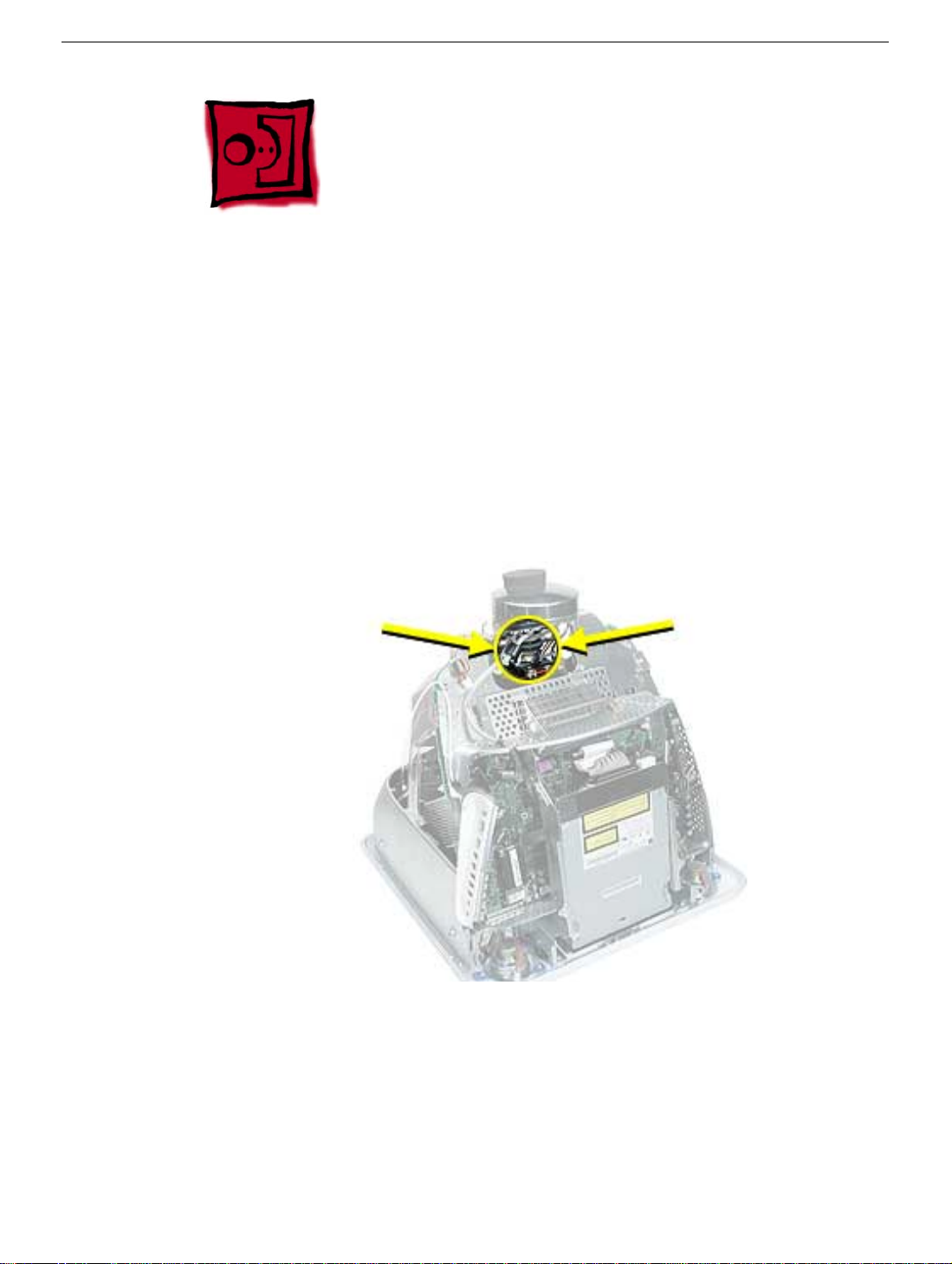
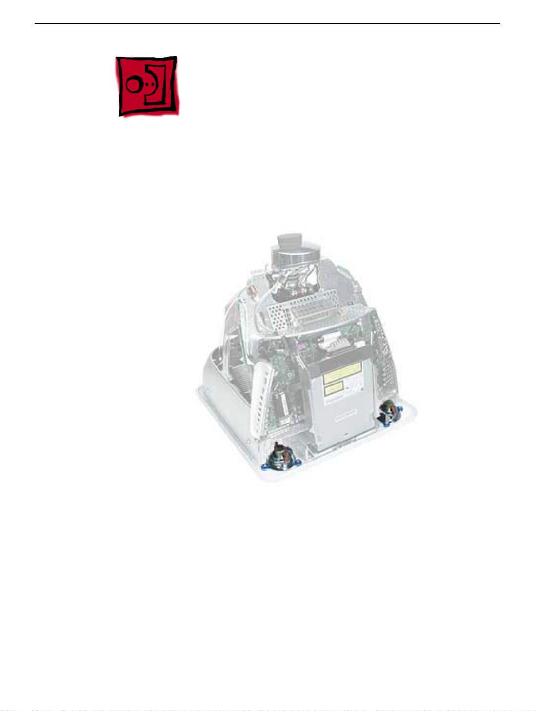
CRT Neck/Display/Analog Assembly Handling Information
Handling
Important:
when working with the display/analog assembly.
Do NOT lift, handle, bump, or manipulate the CRT neck/neck board (see arrows below) on
the Display/Analog assembly. Modules damaged by mishandling are NOT covered by
Apple Warranty. Apple Authorized Service Providers can be liable for broken CRT necks
due to improper handling.
Caution
handling the assembly. Lift the assembly from the metal chassis; never lift the assembly
from the neck. I
It is imperative that proper handling and packaging guidelines be followed
: The metal chassis has sharp edges, you may want to wear gloves when
Packing a Defective Display/Analog Assembly
The packing procedure is included with the replacement display/analog assembly.
Incorrect packaging can result in damaged eMac (ATI Graphics) displays. Please read and
follow the directions enclosed in the shipping box of the new display prior to packaging the
defective assembly. AASPs can be liable for broken CRT necks due to improper packing
and handling.
2 -
eMac (ATI Graphics) and eMac (USB 2.0) Take Apart
CRT Neck/Display/Analog Assembly Handling Infor-
Page 10
Rear Housing
Tools
• 2.5 mm hex (for the rear housing)
• Phillips #2 screwdriver
Part Location
Rear Housing
Preliminary Steps
Before you begin, do the following:
• Place the computer face down on an ESD mat.
eMac (ATI Graphics) and eMac (USB 2.0) Take Apart -
3
Page 11
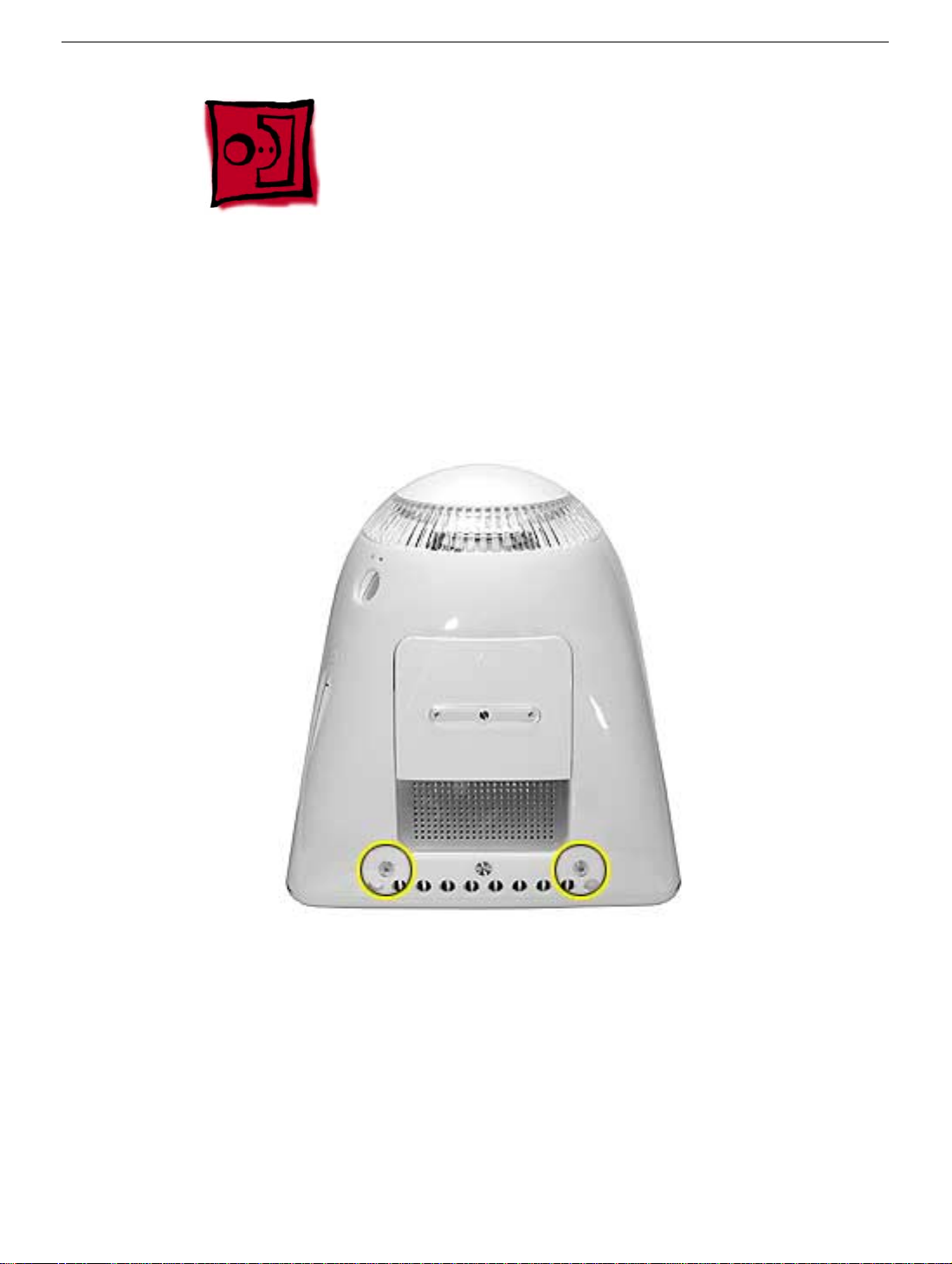
Procedure
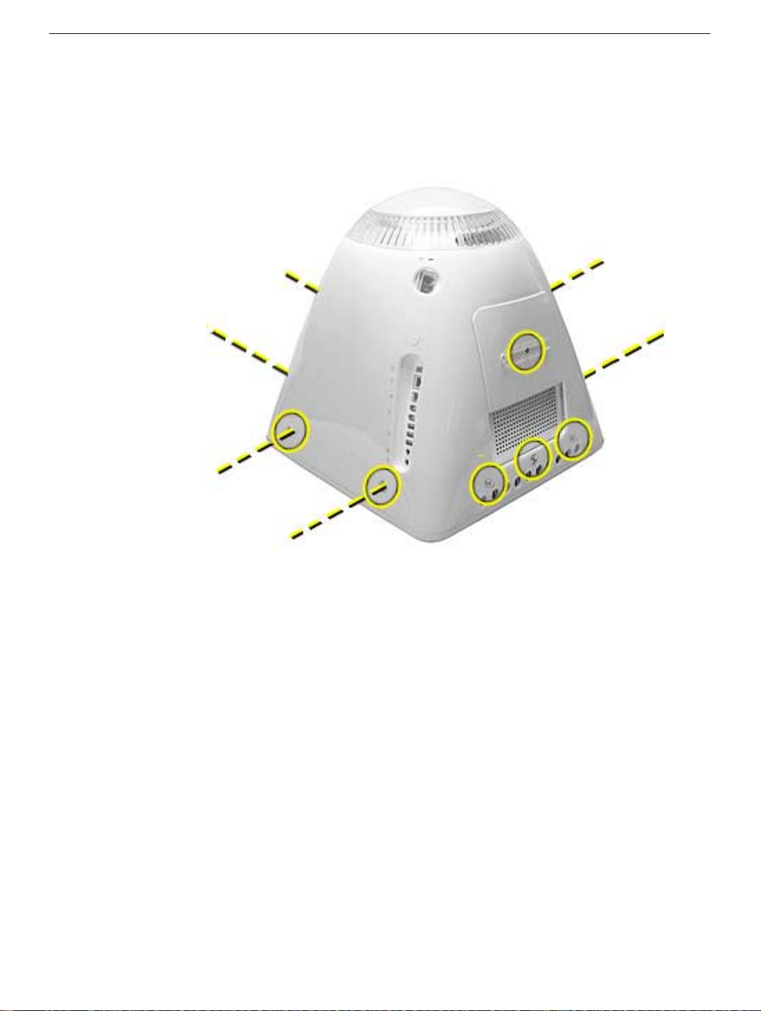
1. Remove seven hex screws around the perimeter of the rear housing.
2. Remove the three Phillips screws; one used for the user access door, and two used for
the feet.
Note:
Newer models have a captive screws.
4 -
eMac (ATI Graphics) and eMac (USB 2.0) Take Apart
Rear Housing
Page 12
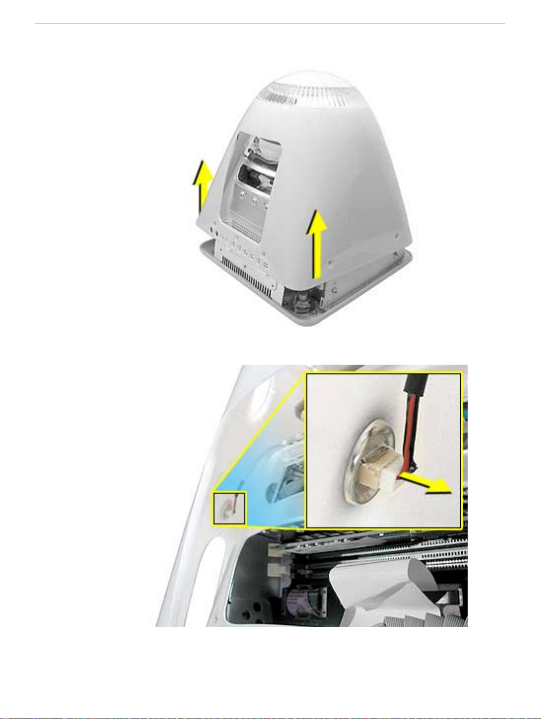
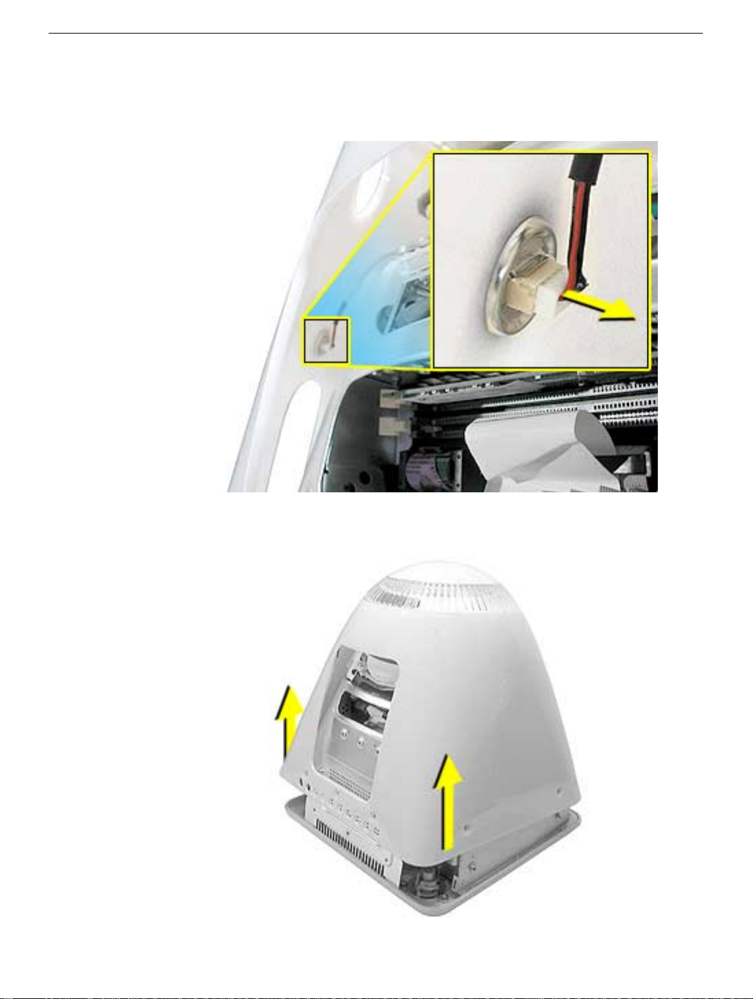
3. Gently lift the rear housing up about four inches.
4. Disconnect the power button cable located on the inside the rear housing.
Rear Housing
5. Lift the rear housing off the computer.
eMac (ATI Graphics) and eMac (USB 2.0) Take Apart -
5
Page 13
User Access Door
Tools
This procedure requires the following tools:
• Phillips #2 screwdriver
Part Location
Preliminary Steps
Before you begin, do the following:
• Place the computer face down on an ESD mat.
6 -
eMac (ATI Graphics) and eMac (USB 2.0) Take Apart
User Access Door
Page 14
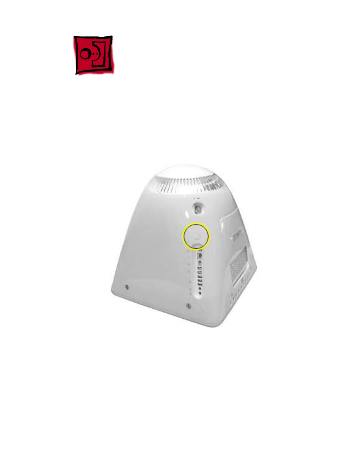
Procedure
1. Remove the screw on the user access door (shown below).
a captive screw.
2. Gently remove the access door.
Note:
Newer models have
User Access Door
eMac (ATI Graphics) and eMac (USB 2.0) Take Apart -
7
Page 15
Feet
Tools
This procedure requires the following tools:
• Phillips #2 screwdriver
Part Location
Preliminary Steps
Before you begin, do the following:
• Place the computer face down on an ESD mat.
8 -
eMac (ATI Graphics) and eMac (USB 2.0) Take Apart
Feet
Page 16
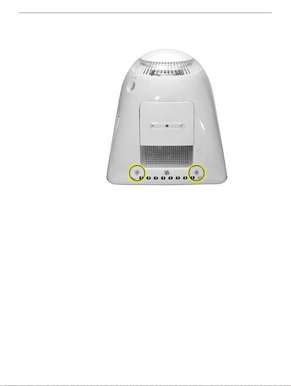
Procedure
1. Remove the two foot screws.
Note:
Newer models use captive screws.
Feet
eMac (ATI Graphics) and eMac (USB 2.0) Take Apart -
9
Page 17
Power Button
Tools
• Needlenose pliers
Note:
Follow the Replacement Note procedure (step 2) only if you are replacing a
defective power button.
Part Location
Preliminary Steps
Before you begin, do the following:
• Place the computer face down on an ESD mat.
• Remove the user access panel.
• Remove the feet.
• Remove the rear housing.
10 -
eMac (ATI Graphics) and eMac (USB 2.0) Take Apart
Power Button
Page 18
Procedure
1. Disconnect the power button cable from the power button located inside the rear
housing.
2. Lift the rear housing off the bezel.
page, “Power Button Cable Check” before replacing the rear housing.
Replacement Note:
Refer to the topic on the next
Power Button
eMac (ATI Graphics) and eMac (USB 2.0) Take Apart -
11
Page 19
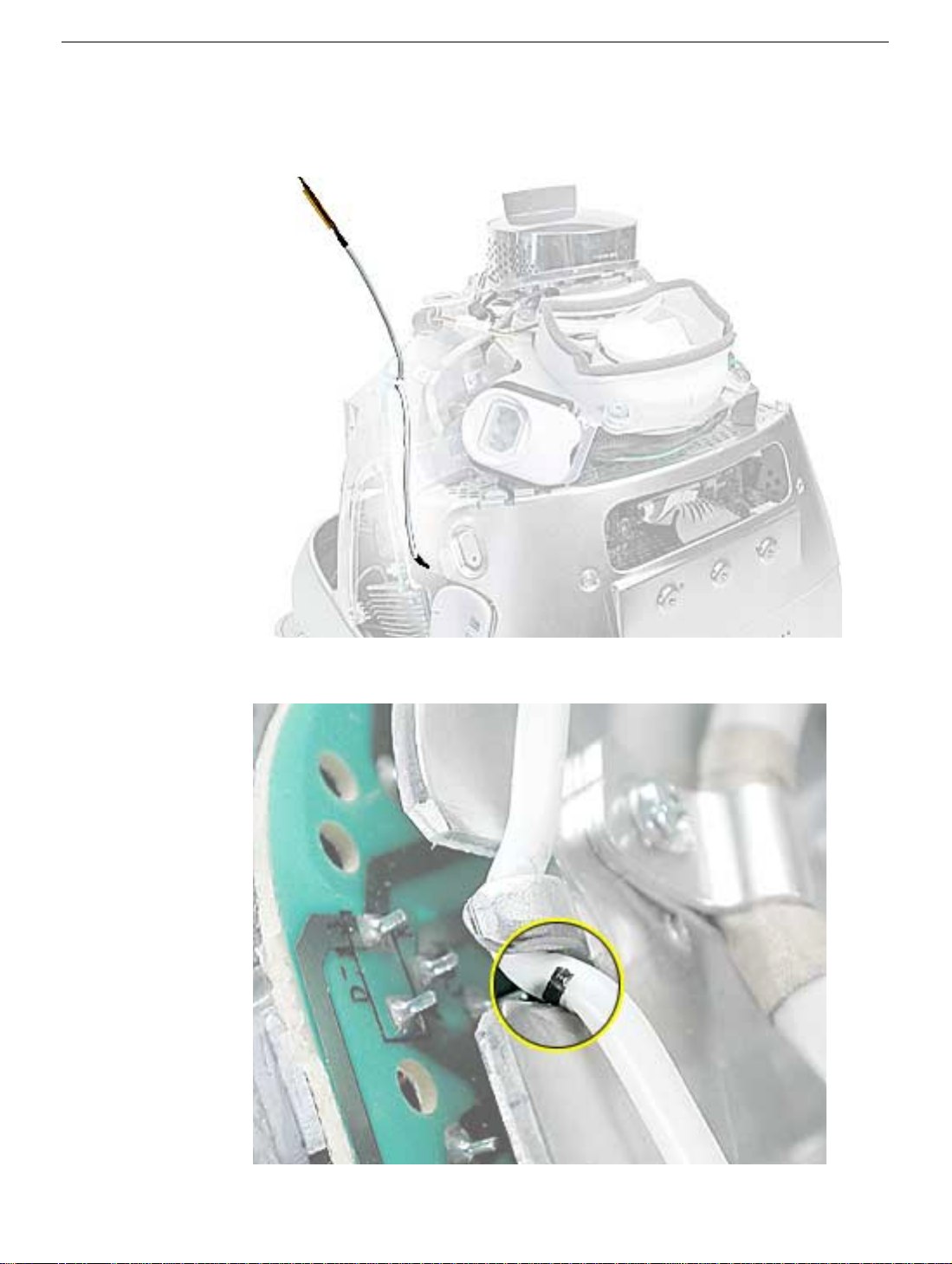
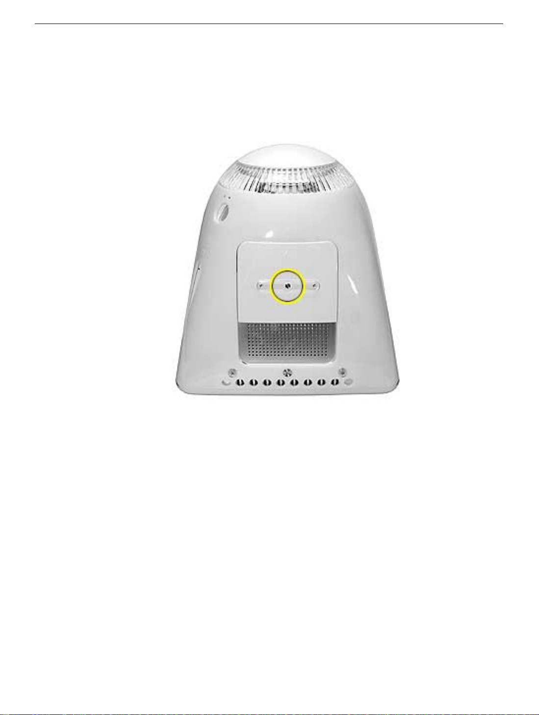
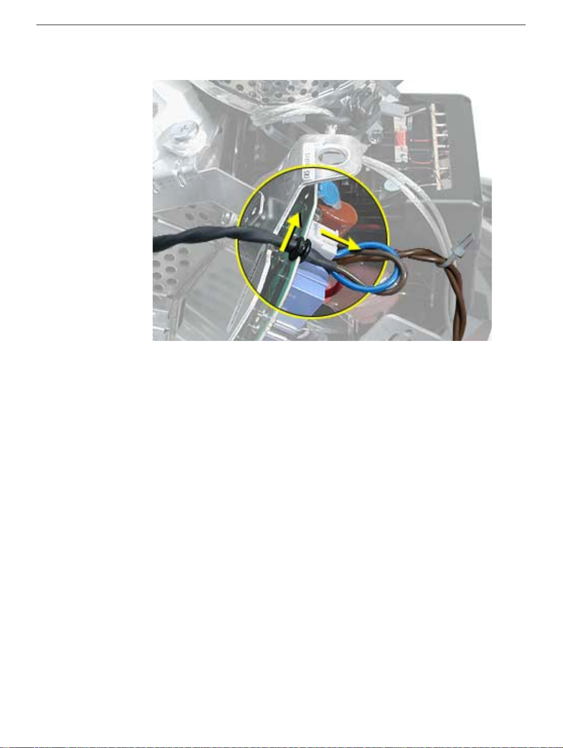
Power Button Cable Check
1. Check that the power button cable in drawn tight before you attach the other end of the
cable to the power button (located inside the rear housing).
2. Also, check that the cable is tucked under the chassis tab (as shown) and that the
black mark on the cable lines up with the chassis (circled below).
12 -
eMac (ATI Graphics) and eMac (USB 2.0) Take Apart
Power Button
Page 20
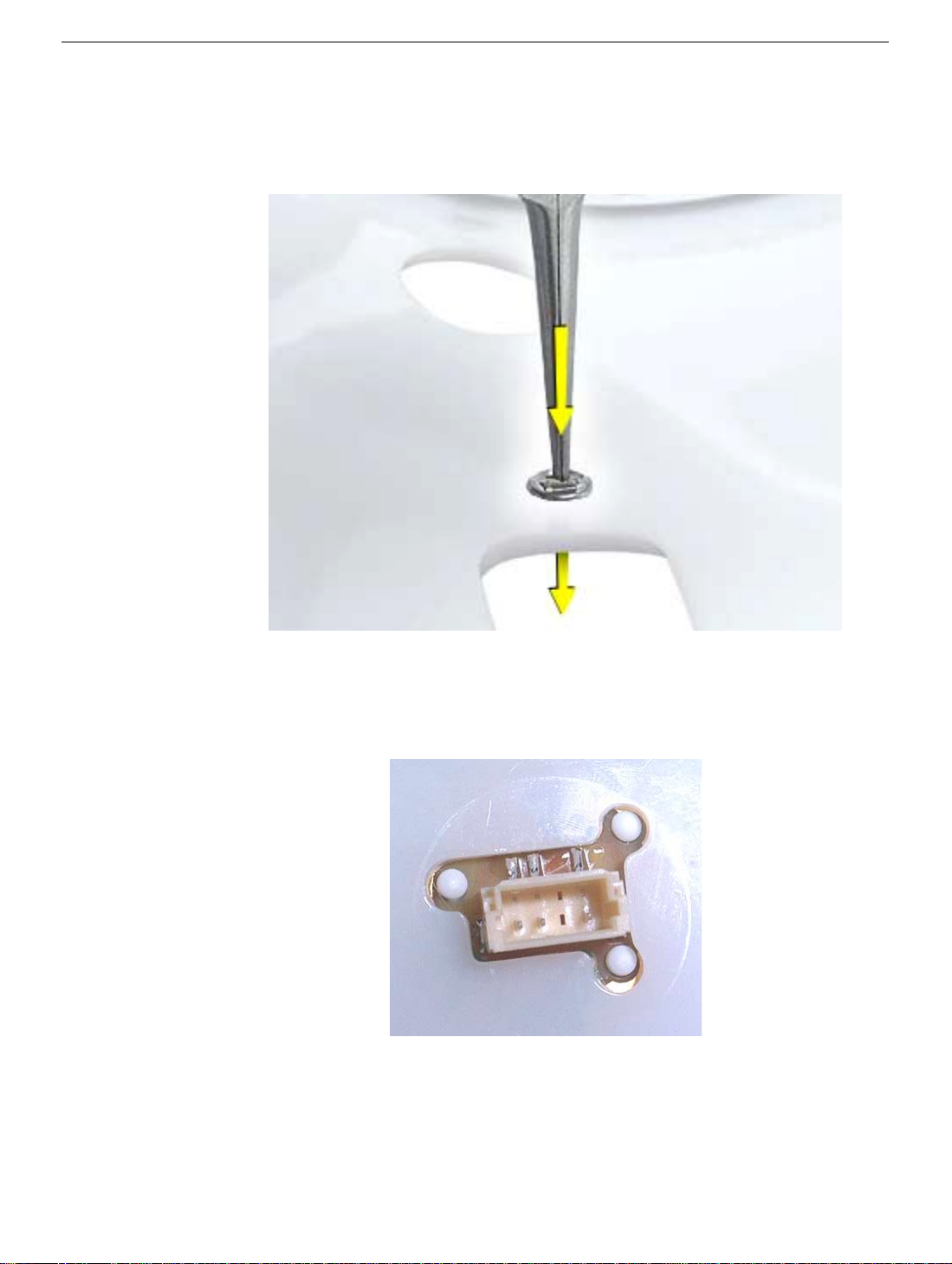
Power Button Replacement
1. Continue with this procedure only if you are replacing a defective power button. With a
needlenose pliers, push the power button through the retaining ring. The power button
will pop off rear housing and the retaining ring may get stuck on the pliers.
2. Obtain the new power button and peel the sticky backing off the power button. Position
the power button into the hole on the rear housing (as shown below).
picture below is looking at the power button from the inside of the rear housing.
3. Place the retaining ring over the power button connector and press down firmly.
Note:
The
Power Button
eMac (ATI Graphics) and eMac (USB 2.0) Take Apart -
13
Page 21
CRT Discharge
Warning:
injury, always review the Service Foundations: CRT Displays course for safety information.
It can be found at: http://service.info.apple.com/service_training/training.html. Click on
Desktop Certification Courses and select the Service Foundations: CRT Displays link.
Warning:
an ongoing ground connection.
This product contains high voltage and a high-vacuum picture tube. To prevent
Never use a grounding wriststrap until after discharging the CRT and setting up
Safety Guidelines:
Whenever the rear housing of the computer is removed and before replacing a module,
you must
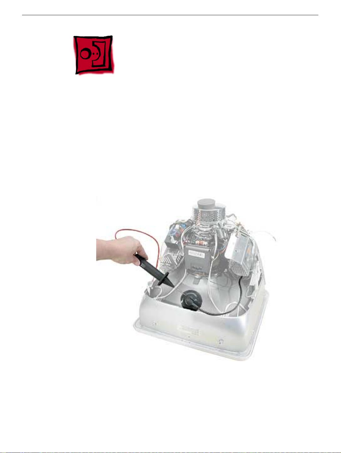
1. Discharge the CRT (shown below) and remove the anode cap.
2. Establish an ongoing ground by using a cable with alligator clips at both ends.
Connect one end to the anode aperture, and connect the other end to the metal CRT
frame (as shown below).
3. With the CRT discharged and the ongoing ground in place wear a grounding
wriststrap to prevent equipment damage from static electricity.
14 -
eMac (ATI Graphics) and eMac (USB 2.0) Take Apart
CRT Discharge
Page 22
Speakers
Tools
This procedure requires the following tools:
• Phillips #2 screwdriver
Part Location
Speakers
Preliminary Steps
Before you begin, do the following:
• Place the computer face down on an ESD mat.
• Remove the user access door.
• Remove the feet.
• Remove the rear housing.
• Discharge the CRT.
eMac (ATI Graphics) and eMac (USB 2.0) Take Apart -
15
Page 23
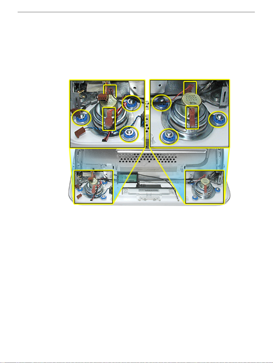
Procedure
1. Remove the left and right speaker screws (circled in the top photos). There are three
screws per speaker.
2. Disconnect the two spade connectors (see rectangles in the top photos) on each
speaker.
3. Lift the speakers out of the front bezel.
16 -
eMac (ATI Graphics) and eMac (USB 2.0) Take Apart
Speakers
Page 24
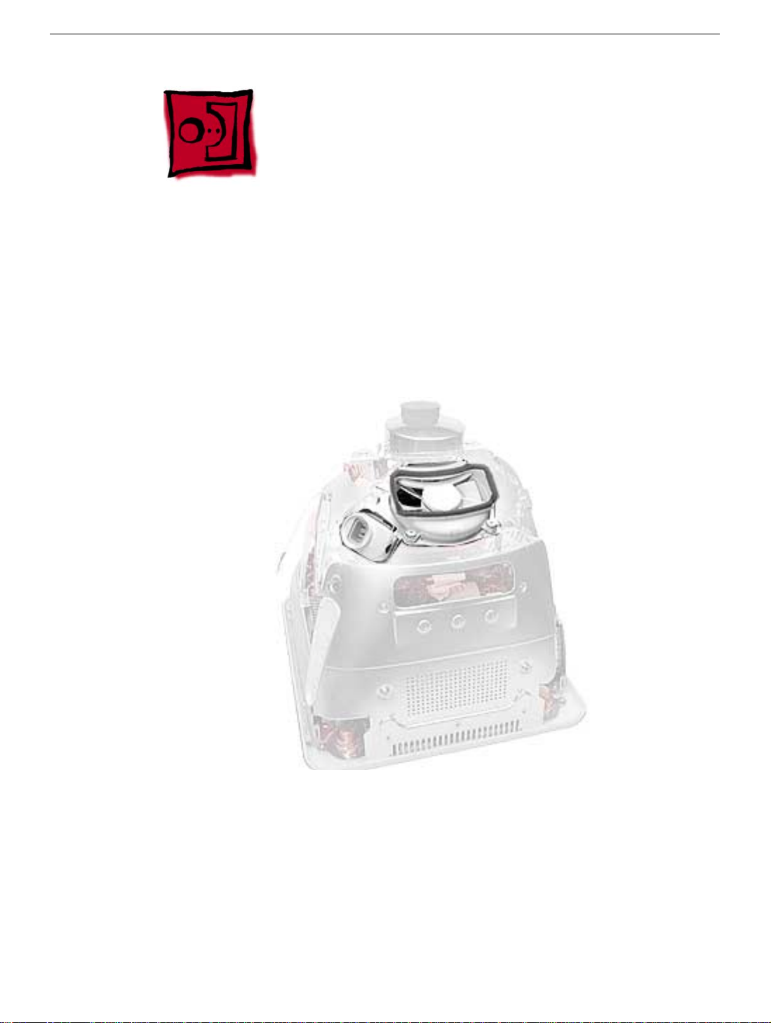
Fan
Tools
This procedure requires the following tools:
• Phillips #2
Part Location
Fan
Preliminary Steps
Before you begin, do the following:
• Place the computer face down on an ESD mat.
• Remove the user access door.
• Remove the feet.
• Remove the rear housing.
• Discharge the CRT.
eMac (ATI Graphics) and eMac (USB 2.0) Take Apart -
17
Page 25
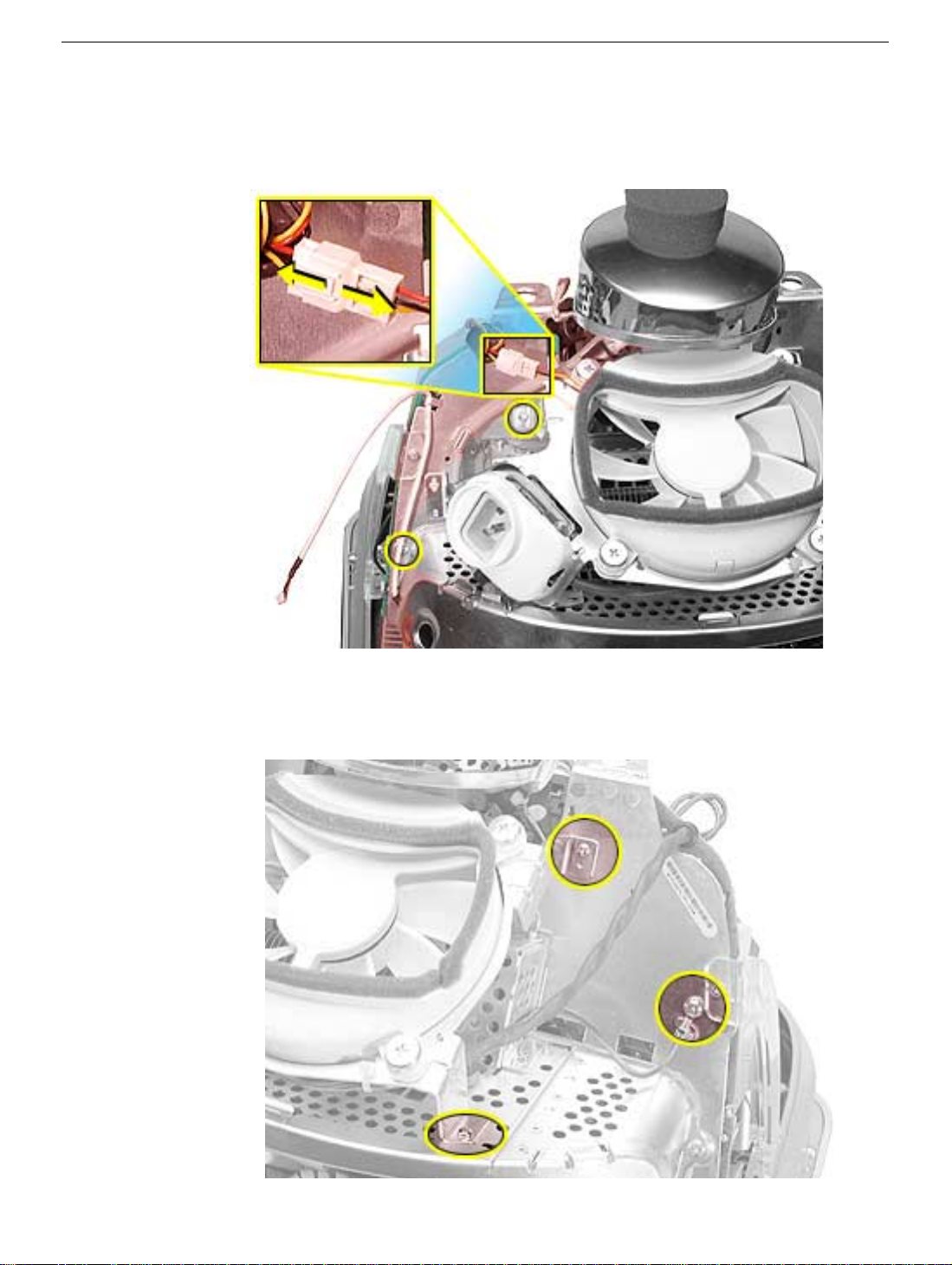
Procedure
1. On the left side of the fan, disconnect the fan cable and remove the two screws
(circled).
2. On the right side of the fan, remove three screws (the green cable goes to the ground
screw).
and the screw on the bottom left is a fine thread screw.
Replacement Note:
The screw circled on the top left is a self-tapping screw,
18 -
eMac (ATI Graphics) and eMac (USB 2.0) Take Apart
Fan
Page 26
3. Wiggle the fan cable up and out of the groove in the chassis and then disconnect the
fan connector from the board.
4. To remove the fan, turn the computer so the fan is facing you. Grab onto the fan near
the AC plug and the bottom right corner of the fan. Gently pull the fan toward you and
away from the chassis. Be very careful of the CRT neck.
Fan
eMac (ATI Graphics) and eMac (USB 2.0) Take Apart -
19
Page 27
Faraday Plate
Tools
This procedure requires the following tools:
• Phillips #2
Part Location
Preliminary Steps
• Place the computer face down on an ESD mat.
• Remove the user access door.
• Remove the feet.
• Remove the rear housing.
• Discharge the CRT.
20 -
eMac (ATI Graphics) and eMac (USB 2.0) Take Apart
Faraday Plate
Page 28
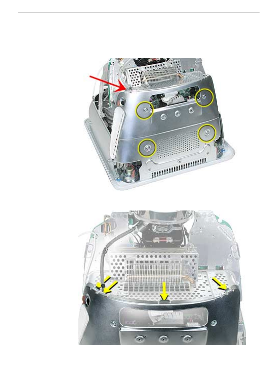
Procedure
1. Remove the four screws on the Faraday plate. Replacement Note: Note the position
of the gray cable (see red arrow) on the top left side of the Faraday plate. Be careful
the cable doesn’t get pinched when the Faraday plate is replaced.
2. Gently pry the top half of the Faraday plate away from the chassis in the direction of
the arrows. Note: The gray cable (on left) rests in a groove under the Faraday plate.
Faraday Plate
eMac (ATI Graphics) and eMac (USB 2.0) Take Apart - 21
Page 29
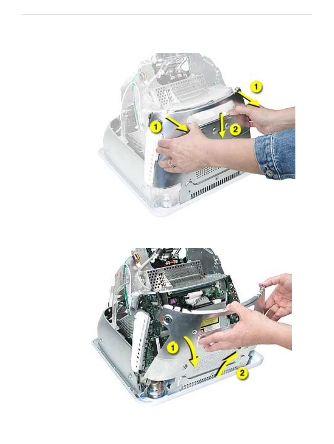
3. Pull the Faraday plate back (#1) and then push it down (#2) to unhook the metal tabs
on the Faraday plate from the cutouts (see graphic on the next page) in the chassis.
4. Continue to pull the Faraday plate back (#1) to unhook the tabs from the chassis. Pull
the Faraday plate up (#2) to remove it from the chassis.
22 - eMac (ATI Graphics) and eMac (USB 2.0) Take Apart
Faraday Plate
Page 30
Faraday Replacement
1. Looking from the top down, line up the metal tabs with the cutouts in the chassis
(circled on the right and left) and the slots on the Faraday plate with the white plastic
guides on the bezel (circled on the right and left sides of the optical drive).
2. Raise the Faraday plate up and attach it to the frame on the digital assembly. Be
careful that the gray cable (shown in step 2 on the previous page) does not get
pinched in the Faraday plate.
Faraday Plate
eMac (ATI Graphics) and eMac (USB 2.0) Take Apart - 23
Page 31

Optical Drive
Tools
This procedure requires the following tools:
• Phillips #2 screwdriver
Part Location
Preliminary Steps
Before you begin, do the following:
• Place the computer face down on an ESD mat.
• Remove the user access door.
• Remove the feet.
• Remove the rear housing.
• Discharge the CRT.
• Remove the Faraday plate.
24 - eMac (ATI Graphics) and eMac (USB 2.0) Take Apart
Optical Drive
Page 32

Procedure
1. Disconnect the data cable and the power cable at the top of the optical drive.
2. Remove the four screws connecting the optical drive to the chassis.
3. Holding the optical drive by the top or bottom end, tilt the optical drive out of the
chassis. Replacement Note: Remove the EMI shield off the end of the defective
optical drive. Place the EMI shield on the replacement drive.
Optical Drive
eMac (ATI Graphics) and eMac (USB 2.0) Take Apart - 25
Page 33

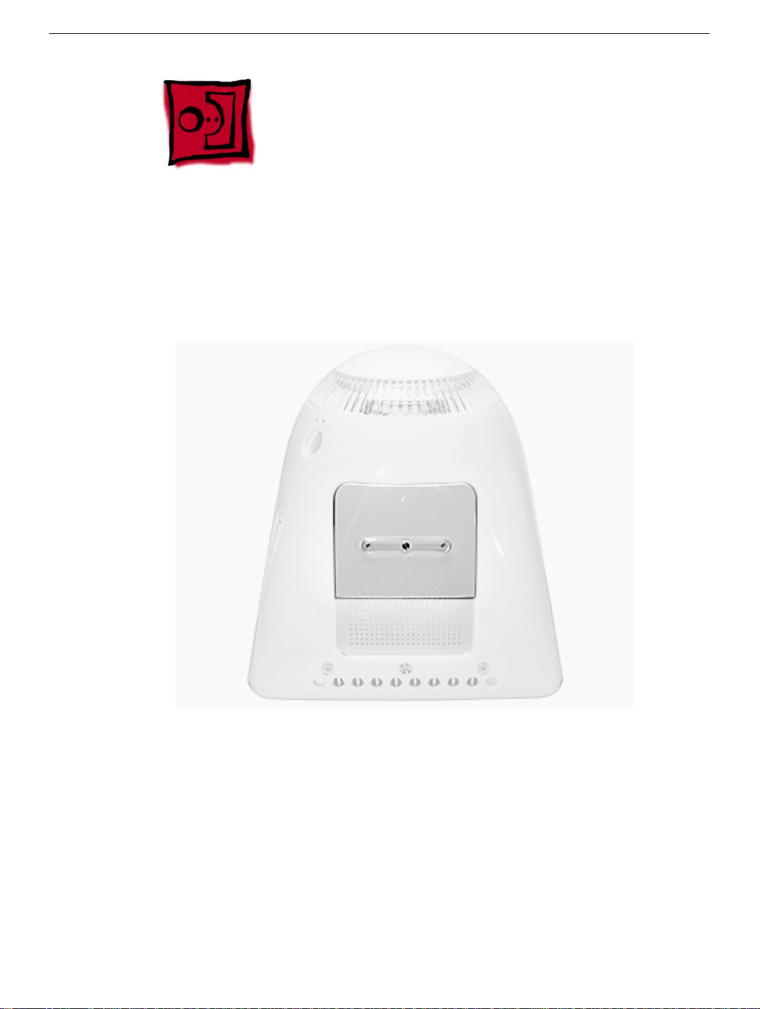
No Optical Configuration
Note: There is new configuration on the eMac (USB 2.0) that is sold without an optical
drive (shown below).
If you decide to add an optical drive at a later date, order the parts mentioned in the
Upgrades chapter under the topic “Optical Drive Installation.”
26 - eMac (ATI Graphics) and eMac (USB 2.0) Take Apart
Optical Drive
Page 34

Bluetooth
Tools
This procedure requires the following tools:
• Phillips #2
Part Location
Bluetooth
Preliminary Steps
Before you begin, do the following:
• Place the computer face down on an ESD mat
• Remove the user access door
• Remove the feet
• Remove the rear housing
• Discharge the CRT
• Remove the fan
• Remove the Faraday plate
eMac (ATI Graphics) and eMac (USB 2.0) Take Apart - 27
Page 35

Procedure
1. Remove the two screws on the Bluetooth board.
2. With two fingers, gently wiggle the Bluetooth board off the connector on the logic
board.
28 - eMac (ATI Graphics) and eMac (USB 2.0) Take Apart
Bluetooth
Page 36

3. Turn the Bluetooth board over and carefully disconnect the Bluetooth antenna cable
from the board.
4. To remove the Bluetooth antenna cable, pull the cable through the hole in the chassis.
Bluetooth
eMac (ATI Graphics) and eMac (USB 2.0) Take Apart - 29
Page 37

5. WIth the nylon tool (922-5065), pry the antenna fixture off the front bezel. The antenna
is attached to the front bezel with double-stick tape.
30 - eMac (ATI Graphics) and eMac (USB 2.0) Take Apart
Bluetooth
Page 38

Digital Assembly
Tools
This procedure requires the following tools:
• Phillips #2
Part Location
Digital Assembly
eMac (ATI Graphics) and eMac (USB 2.0) Take Apart - 31
Page 39

Part Location (without optical drive)
Note: There is new configuration on the eMac (USB 2.0) that is sold without an optical
drive (shown below). The take apart for the digital assembly is the same.
Preliminary Steps
Before you begin, do the following:
• Place the computer face down on an ESD mat
• Remove the user access door
• Remove the feet
• Remove the rear housing
• Discharge the CRT
• Remove the fan
• Remove the Faraday plate
• Remove the AirPort Extreme Card (if present)
• Remove the Bluetooth board (if present)
32 - eMac (ATI Graphics) and eMac (USB 2.0) Take Apart
Digital Assembly
Page 40

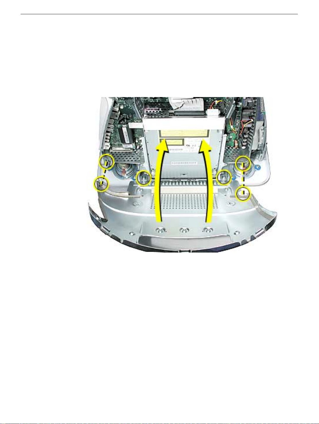
Procedure
1. With the back of the computer facing you, remove the three screws near the top of the
digital assembly.
2. On the top left side of the digital assembly, disconnect the power button cable and the
video cable Note: The power connector (the smaller connector) was on the other side
of the board on previous eMac models. This picture shows the most recent model.
Digital Assembly
eMac (ATI Graphics) and eMac (USB 2.0) Take Apart - 33
Page 41

3. Remove two screws; one on each side of the digital assembly.
4. On the bottom left side of the digital assembly, remove three screws.Note: The two
screws (towards the top of this photo) are the same type screw; the third screw is a
larger, self-tapping screw that attaches to the front bezel.
34 - eMac (ATI Graphics) and eMac (USB 2.0) Take Apart
Digital Assembly
Page 42

5. Disconnect the four cable connectors on the bottom left side of the assembly. From left
to right the connectors are: microphone, fan, LED, and speakers.
6. Remove the two screws on the bottom right side of the assembly. Note: The screw
that attaches to the plastic bezel is a larger, self-tapping screw.
Digital Assembly
eMac (ATI Graphics) and eMac (USB 2.0) Take Apart - 35
Page 43

7. Hold the digital assembly by the sides and pull the assembly straight back. The digital
assembly disconnects from the blind mate connector (circled) on the chassis. Set the
digital assembly aside.
36 - eMac (ATI Graphics) and eMac (USB 2.0) Take Apart
Digital Assembly
Page 44

Hard Drive
Tools
This procedure requires the following tools:
• Phillips #2
• Phillips #1
Part Location
Hard Drive
Preliminary Steps
Before you begin, do the following:
• Place the computer face down on an ESD mat.
• Remove the user access door.
• Remove the feet.
• Remove the rear housing.
• Discharge the CRT.
eMac (ATI Graphics) and eMac (USB 2.0) Take Apart - 37
Page 45

• Remove the fan.
• Remove the Faraday plate.
• Remove the digital assembly.
38 - eMac (ATI Graphics) and eMac (USB 2.0) Take Apart
Hard Drive
Page 46

Procedure
1. Remove the four screws along the back of the metal chassis. Note: The two outer
screws are fine thread screws.
2. Gently unhook (see circle) and lift the hard drive carrier up and off the chassis. Flip the
drive carrier over to access the data and power cables.
Hard Drive
eMac (ATI Graphics) and eMac (USB 2.0) Take Apart - 39
Page 47

3. With the drive carrier flipped over (#1), disconnect the data cable (#2) and the power
cable (#3) from the hard drive.
4. To remove the hard drive from the carrier, remove two screws on the side of the
carrier.
40 - eMac (ATI Graphics) and eMac (USB 2.0) Take Apart
Hard Drive
Page 48

5. Tilt the drive to access the cable. Disconnect the cable from the hard drive. Note: If
you are replacing the drive carrier, review the procedure “Thermal Pad and EMI
Replacement” below.
Thermal Pad and EMI Replacement
1. If you are replacing the hard drive carrier, attach the thermal pad, and two rubber
bumpers to the top side of the carrier. Note: These pieces come with the replacement
carrier. Then, go on to the next step.
Hard Drive
eMac (ATI Graphics) and eMac (USB 2.0) Take Apart - 41
Page 49

2. Attach two the EMI pads to the bottom side of the carrier.
42 - eMac (ATI Graphics) and eMac (USB 2.0) Take Apart
Hard Drive
Page 50

Logic Board Heatsink
Tools
This procedure requires the following tools:
• Screwdriver to pry the heatsink clip
Part Location
Preliminary Steps
Before you begin, do the following:
• Place the computer face down on an ESD mat.
• Remove the user access door.
• Remove the feet.
• Remove the rear housing.
• Discharge the CRT.
• Remove the fan.
• Remove the Faraday plate.
• Remove the digital assembly.
• Remove the hard drive carrier.
Logic Board Heatsink
eMac (ATI Graphics) and eMac (USB 2.0) Take Apart - 43
Page 51

Procedure
1. Remove the one screw attaching to the chassis (on the top left side). Next, with a
nylon probe tool (922-5065), push the heatsink clip through the hole in the logic board.
The clip will come loose on the top side of the logic board.
2. Unclip the other end of the heatsink clip on the top side of the logic board.
44 - eMac (ATI Graphics) and eMac (USB 2.0) Take Apart
Logic Board Heatsink
Page 52

3. Lift the heatsink from the logic board. Warning: The the CPU heatsink should have
minimum handling of the fins. Be very careful when handling this part.
Replacement Note: Whenever the heatsink is removed, the bottom side of the
heatsink and the top of the microprocessor must be cleaned and new thermal paste
must be applied to the microprocessor. If the mating surfaces are not cleaned and
thermal paste is not applied, the CPU may overheat and become damaged. Refer to
the next topic, “Thermal Paste Application”.
Logic Board Heatsink
eMac (ATI Graphics) and eMac (USB 2.0) Take Apart - 45
Page 53

Thermal Paste Application
The microprocessor uses a heatsink/thermal pipe to transfer heat away. Whenever the
heatsink is removed, the bottom side of the heatsink and the top of the microprocessor
must be cleaned and thermal paste must be applied. If the mating surfaces are not
cleaned and thermal paste is not applied, the CPU may overheat and become damaged.
Tools
This procedure requires the following tools:
• Plastic stylus or nylon probe tool (922-5065) to remove the old thermal paste
• Thermal paste (922-4757), each tube contains 4-5 applications
Procedure
1. Thoroughly clean the thermal film from the heatsink surface with a plastic stylus or the
nylon probe tool. Do not use an abrasive material or liquid cleaner. Important: Be
extremely careful not to bend the fins on the heatsink.
46 - eMac (ATI Graphics) and eMac (USB 2.0) Take Apart
Thermal Paste Application
Page 54

2. Carefully remove the old thermal paste from the surface of the microprocessor. Gently
remove the paste with a plastic stylus or nylon probe tool.
3. Squeeze a drop of thermal paste onto the middle of the microprocessor as
shown.
Thermal Paste Application
eMac (ATI Graphics) and eMac (USB 2.0) Take Apart - 47
Page 55

4. Spread the paste evenly over the processor. Important: On this product, it is critical
to spread the paste over the processor, or the chip could overheat.
5. Reinstall the heatsink and the heatsink clip.
48 - eMac (ATI Graphics) and eMac (USB 2.0) Take Apart
Thermal Paste Application
Page 56

Logic Board
Tools
This procedure requires the following tools:
• Phillips #2 screwdriver
Part Location
Logic Board
Preliminary Steps
Before you begin, do the following:
• Place the computer face down on an ESD mat.
• Remove the user access door.
• Remove the feet.
• Remove the rear housing.
• Discharge the CRT.
• Remove the fan.
• Remove the Faraday plate.
eMac (ATI Graphics) and eMac (USB 2.0) Take Apart - 49
Page 57

• Remove the digital assembly.
• Remove the hard drive carrier
• Remove the AirPort Extreme Card (if present)
50 - eMac (ATI Graphics) and eMac (USB 2.0) Take Apart
Logic Board
Page 58

Procedure
1. Disconnect the optical data cable, the optical power cable and release the heatsink
clip. Note: On education models the optical cables are not present because there
isn’t an optical drive.
2. Remove the down converter screw that attaches to the chassis frame.
Logic Board
eMac (ATI Graphics) and eMac (USB 2.0) Take Apart - 51
Page 59

3. On the left side, disconnect the power button cable and the modem cable. Note: On
newer models the power button connector is in the same general location, but on the
other side of the logic board.
4. Turn the assembly so the logic board is facing up. Remove the heatsink.
52 - eMac (ATI Graphics) and eMac (USB 2.0) Take Apart
Logic Board
Page 60

5. Remove the four screws on the logic board.
6. To remove the logic board from the chassis frame, unhook the chassis clips under the
I/O panel and on the top right side of the chassis frame.
Logic Board
eMac (ATI Graphics) and eMac (USB 2.0) Take Apart - 53
Page 61

7. Hold the board by the down converter (#1) and gently pull the chassis frame (#2)
forward, away from the board. Remove the logic board (#3) from the chassis frame.
Carefully maneuver the board out of the frame.
Important: The microprocessor uses a heatsink/thermal pipe to transfer heat away.
Whenever the heatsink is removed, the bottom side of the heatsink and the top of the
microprocessor must be cleaned and thermal paste must be applied to the
microprocessor. If the mating surfaces are not cleaned and thermal paste is not
applied, the CPU may overheat and become damaged. Refer to “Thermal Paste
Application” in this chapter.
54 - eMac (ATI Graphics) and eMac (USB 2.0) Take Apart
Logic Board
Page 62

Logic Board Identification:
There is one 800 MHZ board, three 1 GHz logic boards, and one 1.25 GHz board for this
product. The boards need to be exchanged like-for-like. Use the EEE codes to identify the
boards. The graphic below shows the general location of the barcode label for the logic
boards.
• 661-2853, 800 MHz: EEE code PLB
• 661-2854, 1 GHz: EEE code, NMA
• 661-3014, 1 GHz, Ver. 2: EEE code, Q11, which will either be a sticker above the
barcode (shown below), or Q11 will be embedded in the barcode.
• 661-3279 1 GHz board, USB 2.0: EEE code QDJ or QHL.
• 661-3280 1.25 GHz board, USB 2.0: EEE code QDK or QHM
Logic Board
eMac (ATI Graphics) 1 GHz logic board 661-3014
eMac (ATI Graphics) and eMac (USB 2.0) Take Apart - 55
Page 63

eMac (USB 2.0) 1.25 GHz logic board, 661-3280
Replacement Note: Before returning the logic board to Apple, remove the following items:
• I/O panel frame
• RJ-11 connector (if present)
• Modem board
• Memory
• Heatsink
• Down converter
• AirPort Extreme Card (if present)
• Bluetooth board (if present)
56 - eMac (ATI Graphics) and eMac (USB 2.0) Take Apart
Logic Board
Page 64

Down Converter
Tools
This procedure requires the following tools:
• Phillips #2
Part Location
Down Converter
Preliminary Steps
Before you begin, do the following:
• Place the computer face down on an ESD mat.
• Remove the user access door.
• Remove the feet.
• Remove the rear housing.
• Discharge the CRT.
• Remove the fan.
• Remove the Faraday plate.
• Remove the digital assembly.
eMac (ATI Graphics) and eMac (USB 2.0) Take Apart - 57
Page 65

Procedure
1. Remove the screw attaching the down converter to the chassis frame.
2. Turn the logic board right side up. Hold the board by the down converter (#1) and
gently pull the chassis frame (#2) away from the board. Remove the logic board (#3)
out of the chassis frame. Carefully maneuver the logic board out of the frame.
58 - eMac (ATI Graphics) and eMac (USB 2.0) Take Apart
Down Converter
Page 66

3. Important: The down converter board is fragile. Be careful not to flex the board too
much when removing or inserting a replacement down converter.
4. Turn the logic board over so you can see the logic board-to-down converter connector.
Pull the down converter in the direction of the arrow to disconnect the board from the
logic board.
Down Converter
eMac (ATI Graphics) and eMac (USB 2.0) Take Apart - 59
Page 67

5. Slide the down converter off the logic board in the direction of the arrow. Important:
For replacement instructions, refer to the next topic.
60 - eMac (ATI Graphics) and eMac (USB 2.0) Take Apart
Down Converter
Page 68

Replacing the Down Converter
1. Important: Be careful when installing the down converter; the board is fragile. Hold
the down converter by the top of the board (as shown below). Carefully slide the down
converter onto the logic board in the direction of the arrow.
2. With the down converter in place, squeeze the pins (circled below) and the connector
together for a solid connection.
Down Converter
eMac (ATI Graphics) and eMac (USB 2.0) Take Apart - 61
Page 69

I/O Panel
Tools
This procedure requires the following tools:
• Phillips #2 screwdriver
Part Location
Preliminary Steps
Before you begin, do the following:
• Place the computer face down on an ESD mat.
• Remove the user access door.
• Remove the feet.
• Remove the rear housing.
• Discharge the CRT.
• Remove the fan.
• Remove the Faraday plate.
62 - eMac (ATI Graphics) and eMac (USB 2.0) Take Apart
I/O Panel
Page 70

• Remove the digital assembly.
• Remove the logic board.
I/O Panel
eMac (ATI Graphics) and eMac (USB 2.0) Take Apart - 63
Page 71

Procedure
1. Remove the logic board from the chassis frame to access the I/O panel.
2. Remove the two I/O panel screws.
64 - eMac (ATI Graphics) and eMac (USB 2.0) Take Apart
I/O Panel
Page 72

3. First, pull the I/O panel away from the ports (#1) on the logic board. Next, carefully pull
the I/O fence away from the connectors on the end of the board (#2).
I/O Panel
eMac (ATI Graphics) and eMac (USB 2.0) Take Apart - 65
Page 73

RJ-11 Cable
Tools
• Nylon probe tool (922-5065)
Part Location
Preliminary Steps
Before you begin, do the following:
• Place the computer face down on an ESD mat.
• Remove the user access door.
• Remove the feet.
• Remove the rear housing.
• Discharge the CRT.
• Remove the fan.
• Remove the Faraday plate.
• Remove the digital assembly.
• Remove the logic board
• Remove the I/O panel
66 - eMac (ATI Graphics) and eMac (USB 2.0) Take Apart
RJ-11 Cable
Page 74

Procedure
1. Disconnect the RJ-11 cable from the modem.
2. Turn over the logic board. There is a small pry slot on the board for a screwdriver blade
to get behind the connector. See the next step.
RJ-11 Cable
eMac (ATI Graphics) and eMac (USB 2.0) Take Apart - 67
Page 75

3. Carefully push the RJ-11 port connector off the logic board with a nylon probe tool or
screwdriver.
68 - eMac (ATI Graphics) and eMac (USB 2.0) Take Apart
RJ-11 Cable
Page 76

AirPort Extreme Card
Tools
This procedure requires the following tools:
• Phillips #2
Part Location
Preliminary Steps
Before you begin, do the following:
• Place the computer so that the front of the computer faces you.
AirPort Extreme Card
eMac (ATI Graphics) and eMac (USB 2.0) Take Apart - 69
Page 77

Procedure
1. Press the optical door in on one side and pull the door open on the other side to
access the AirPort access panel.
70 - eMac (ATI Graphics) and eMac (USB 2.0) Take Apart
AirPort Extreme Card
Page 78

2. Loosen the two captive screws on the access panel. Remove the access panel. Note:
On entry level models you won’t see the optical tray when you remove the access
panel. The access panel is a”blank” piece of plastic that covers the hole where an
optical drive would be present (see next graphic).
3. The picture below shows the entry level eMac model Airport access door . Notice the
absence of the optical drive.
AirPort Extreme Card
eMac (ATI Graphics) and eMac (USB 2.0) Take Apart - 71
Page 79

4. Remove the access panel.
5. Untuck the clear tab attached to the AirPort Extreme Card.
72 - eMac (ATI Graphics) and eMac (USB 2.0) Take Apart
AirPort Extreme Card
Page 80

6. Pull the AirPort Extreme Card out of the slot a little bit to access the antenna
connected to the card.
7. Disconnect the antenna cable from the AirPort Extreme card.
8. Pull the tab to remove the AirPort Extreme card from the slot. Refer to the next page to
AirPort Extreme Card
see the internal difference of the entry level eMac.
eMac (ATI Graphics) and eMac (USB 2.0) Take Apart - 73
Page 81

9. This picture shows removing the AirPort card from the entry level eMac model. Notice
the metal optical plate covering the location where the optical drive would be present.
74 - eMac (ATI Graphics) and eMac (USB 2.0) Take Apart
AirPort Extreme Card
Page 82

LED
Tools
This procedure requires the following tools:
• Phillips #2
Part Location
LED
Preliminary Steps
Before you begin, do the following:
• Place the computer face down on an ESD mat.
• Remove the user access door.
• Remove the feet.
• Remove the rear housing.
• Discharge the CRT.
eMac (ATI Graphics) and eMac (USB 2.0) Take Apart - 75
Page 83

• Remove the fan.
• Remove the Faraday plate.
76 - eMac (ATI Graphics) and eMac (USB 2.0) Take Apart
LED
Page 84

Procedure
1. Remove one screw and disconnect the LED cable. Important: The connector is very
fragile, remove it gently. Lift the LED board off the front bezel.
LED
eMac (ATI Graphics) and eMac (USB 2.0) Take Apart - 77
Page 85

Front Bezel
Tools
This procedure requires the following tools:
• Phillips #2
Part Location
Preliminary Steps
Before you begin, do the following:
• Place the computer face down on an ESD mat.
• Remove the user access door.
• Remove the feet.
• Remove the rear housing.
• Discharge the CRT.
• Remove the fan.
78 - eMac (ATI Graphics) and eMac (USB 2.0) Take Apart
Front Bezel
Page 86

• Remove the Faraday plate.
• Remove the digital assembly
• Remove the display/analog assembly
Front Bezel
eMac (ATI Graphics) and eMac (USB 2.0) Take Apart - 79
Page 87

Procedure
1. Remove the eight bezel screws. There are three on each side and two at the top of the
bezel.
Important: DO NOT remove the two larger screws circled below, or the two screws
shown in the next photo. If they are removed, the CRT will be out of alignment and
the entire display/analog assembly will need to be replaced.
2. Important: On this side of the computer, do NOT remove the CRT screws located
under the red circles. The CRT will be out of alignment if these screws are removed.
80 - eMac (ATI Graphics) and eMac (USB 2.0) Take Apart
Front Bezel
Page 88

3. Carefully lift the display/analog assembly off the bezel.
4. Remove the microphone, speakers, and LED from the bezel.
5. Note: Remove the antenna board from the display/analog assembly before returning
the display/analog assembly to Apple. Refer to the next procedure, “Antenna Board”
for details.
Front Bezel
eMac (ATI Graphics) and eMac (USB 2.0) Take Apart - 81
Page 89

Antenna Board (eMac ATI Graphics)
Tools
This procedure requires the following tools:
• Phillips #2 screwdriver
• Needlenose pliers or flat blade screwdriver
Part Location
Preliminary Steps
Before you begin, do the following:
• Remove the AirPort Extreme card
• Place the computer face down on an ESD mat.
• Remove the user access door.
• Remove the feet.
• Remove the rear housing.
• Discharge the CRT.
• Remove the fan.
82 - eMac (ATI Graphics) and eMac (USB 2.0) Take Apart
Antenna Board (eMac ATI Graphics)
Page 90

• Remove the Faraday plate.
• Remove the digital assembly.
• Remove the displayl/analog assembly.
Antenna Board (eMac ATI Graphics)
eMac (ATI Graphics) and eMac (USB 2.0) Take Apart - 83
Page 91

Procedure
1. Remove one screw on the antenna board.
Next, peel back the masking tape and pull the unused end of the antenna through the
hole in the digital/analog chassis.
2. Carefully position the computer so that the CRT faces you.
Locate the metal antenna bracket at the top of the CRT. Remove the screw on the
bracket, then pry the antenna cable from the two clips on the side of the CRT.
84 - eMac (ATI Graphics) and eMac (USB 2.0) Take Apart
Antenna Board (eMac ATI Graphics)
Page 92

Antenna Board (eMac USB 2.0)
Tools
This procedure requires the following tools:
• Phillips #2 screwdriver
• Needlenose pliers or flat blade screwdriver
Part Location
Preliminary Steps
Before you begin, do the following:
• Remove the AirPort Extreme card
• Place the computer face down on an ESD mat.
• Remove the user access door.
• Remove the feet.
• Remove the rear housing.
• Discharge the CRT.
• Remove the fan.
Antenna Board (eMac USB 2.0)
eMac (ATI Graphics) and eMac (USB 2.0) Take Apart - 85
Page 93

• Remove the Faraday plate.
• Remove the digital assembly.
• Remove the digital/analog assembly.
86 - eMac (ATI Graphics) and eMac (USB 2.0) Take Apart
Antenna Board (eMac USB 2.0)
Page 94

Procedure
1. Remove the cable from the black clip, remove one screw, and pry the AirPort antenna
from the AirPort access door plate. This is shown with the display/analog assembly
still attached to the front bezel, in a repair situation it would have to be removed.
2. Carefully position the computer so that the CRT faces you.
Locate the metal antenna bracket at the top of the CRT. Remove the screw on the
bracket, then pry the antenna cable from the clip on the side of the CRT.
Antenna Board (eMac USB 2.0)
eMac (ATI Graphics) and eMac (USB 2.0) Take Apart - 87
Page 95

Microphone
Tools
This procedure requires the following tools:
• Phillips #2
Part Location
Preliminary Steps
Before you begin, do the following:
• Place the computer face down on an ESD mat.
• Remove the user access door.
• Remove the feet.
• Remove the rear housing.
• Discharge the CRT.
• Remove the fan.
88 - eMac (ATI Graphics) and eMac (USB 2.0) Take Apart
Microphone
Page 96

• Remove the Faraday plate.
• Remove the digital assembly.
• Remove the display/analog assembly.
Procedure
1. Carefully lift the display/analog assembly from the bezel to access the microphone.
2. Remove the microphone cable from the bezel.
Microphone
eMac (ATI Graphics) and eMac (USB 2.0) Take Apart - 89
Page 97

Door Assembly
Tools
This procedure requires the following tools:
• Phillips #2
Part Location
Preliminary Steps
Before you begin, do the following:
• Place the computer face down on an ESD mat.
• Remove the user access door.
• Remove the feet.
• Remove the rear housing.
• Discharge the CRT.
• Remove the fan.
90 - eMac (ATI Graphics) and eMac (USB 2.0) Take Apart
Door Assembly
Page 98

• Remove the Faraday plate.
• Remove the digital assembly.
Procedure
1. Remove the two screws connecting the door to the front bezel. Remove the door from
the front bezel.
2. Replacement Note: Transfer the serial number label on the inside of the door to the
replacement door.
Door Assembly
eMac (ATI Graphics) and eMac (USB 2.0) Take Apart - 91
Page 99

Memory
Tools
• No tools are required for this procedure
Part Location
Preliminary Steps
Before you begin, do the following:
• Place the computer face down on an ESD mat.
• Unplug all cables except the power cord, from the computer.
• Remove the user access door.
92 - eMac (ATI Graphics) and eMac (USB 2.0) Take Apart
Memory
Page 100

Procedure
1. Touch a metal surface inside the computer. Then unplug the computer.
Important: Always ground yourself before you touch any parts, or remove/install any
components inside the computer. To avoid generating static electricity, do not walk
around until you have finished removing or installing the memory and closed the
computer.
Memory
eMac (ATI Graphics) and eMac (USB 2.0) Take Apart - 93
 Loading...