


Operation
Smart-UPS® VT
10-40 kVA – 400 V
10-30 kVA – 208 V
10-30 kVA – 200 V

About this Manual
IMPORTANT SAFETY INSTRUCTIONS
SAVE THESE INSTRUCTIONS
This manual is intended for the user of the Smart-UPS® VT.
It refers to important safety warnings and instructions, gives an introduction to the display interface, and provides information on operation, load connection, parts replacement, troubleshooting, total power off and restart.
Only graphics of Smart-UPS® VT with built-in batteries are shown in this manual, but the manual is intended for the users of one or more units within the Smart-UPS® VT family range.
Note
:
Companion manuals
For additional information about:
Smart-UPS® VT 400 V:
•Safety – 990-2822
•Receiving and Unpacking – 990-2284
•Receiving and Unpacking (with batteries) – 990-1747
•Installation – 990-2283
•Installation (with batteries) – 990-1598
•Installation (in parallel) – 990-3045
•Installation (MBP CAN I/O Board) – 990-2873 Smart-UPS® VT 208 V:
•Safety – 990-2822
•Receiving and Unpacking (with batteries) – 990-1747
•Installation – 990-2869
•Installation (in parallel) – 990-3045
•Installation (MBP CAN I/O Board) – 990-2873A Smart-UPS® VT 200 V:
•Safety – 990-2822
•Receiving and Unpacking – 990-2358
•Installation – 990-2360
•Installation (in parallel) – 990-3045
•Installation (MBP - CAN I/O Board) – 990-2873
1 |
Smart-UPS® VT 10-40 kVA, 400 V, 208 V, 200 V - Operation |
990-2282A-001 |
About this Manual
How to find updates to this manual
You can check for updates to this manual on the APC Web site (www.apc.com).
2 |
Smart-UPS® VT 10-40 kVA, 400 V, 208 V, 200 V - Operation |
990-2282A-001 |

Contents
Safety................................................................................ |
1 |
Overview........................................................................... |
2 |
User Interface. . . . . . . . . . . . . . . . . . . . . . . . . . . . . . . . . . . . |
. . . . . . . . .2 |
Interface area . . . . . . . . . . . . . . . . . . . . . . . . . . . . . . . . . . |
2 |
Display interface . . . . . . . . . . . . . . . . . . . . . . . . . . . . . . . . |
2 |
Menu tree . . . . . . . . . . . . . . . . . . . . . . . . . . . . . . . . . . . . . |
4 |
Operation.......................................................................... |
6 |
Operation Modes . . . . . . . . . . . . . . . . . . . . . . . . . . . . . . . . . |
. . . . . . . . .6 |
Normal operation . . . . . . . . . . . . . . . . . . . . . . . . . . . . . . . . |
6 |
Battery operation . . . . . . . . . . . . . . . . . . . . . . . . . . . . . . . . |
6 |
Internal bypass operation . . . . . . . . . . . . . . . . . . . . . . . . . . |
6 |
External maintenance bypass operation . . . . . . . . . . . . . . . . . |
6 |
Optional parallel operation . . . . . . . . . . . . . . . . . . . . . . . . . |
6 |
Operation Procedures. . . . . . . . . . . . . . . . . . . . . . . . . . . . . . . . . . . . . .7
How to turn into bypass . . . . . . . . . . . . . . . . . . . . . . . . . . . 7
How to turn into normal operation . . . . . . . . . . . . . . . . . . . 10
How to turn load OFF/ON via the display interface . . . . . . . . . 12
How to view the Status screens . . . . . . . . . . . . . . . . . . . . . 12
How to view Logging and Statistics . . . . . . . . . . . . . . . . . . . 14
How to use the Diags screen . . . . . . . . . . . . . . . . . . . . . . . 15
How to perform a total power off . . . . . . . . . . . . . . . . . . . . . 16
How to perform a restart . . . . . . . . . . . . . . . . . . . . . . . . . . 19
Configuration ................................................................. |
22 |
Settings . . . . . . . . . . . . . . . . . . . . . . . . . . . . . . . . . . . . . . . . . . . . . . . .22
How to change the Clock and the Alarms in the Setting menu . 22
How to change the Beeper setup, the Contrast, and the
Language in the Display menu . . . . . . . . . . . . . . . . . . . . . . 23
990-2282A-001 |
Smart-UPS® VT 10-40 kVA, 400 V, 208 V, 200 V – Operation |
i |
Maintenance................................................................... |
25 |
Parts Replacement . . . . . . . . . . . . . . . . . . . . . . . . . . . . . . . |
. . . . . . . . 25 |
How to determine if you need a replacement part . . . . . . . . . |
25 |
How to return parts to APC . . . . . . . . . . . . . . . . . . . . . . . . |
25 |
How to store the battery modules . . . . . . . . . . . . . . . . . . . . |
26 |
How to replace a Network Management Card . . . . . . . . . . . . |
28 |
How to replace and install a battery module . . . . . . . . . . . . . |
28 |
Troubleshooting ............................................................ |
33 |
Status and Alarm Messages . . . . . . . . . . . . . . . . . . . . . . . |
. . . . . . . . 33 |
Display messages . . . . . . . . . . . . . . . . . . . . . . . . . . . . . . |
33 |
ii |
Smart-UPS® VT 10-40 kVA, 400 V, 208 V, 200 V – Operation |
990-2282A-001 |

Safety
All safety instructions in the Safety Sheet (990-2822) shall be read, understood, and followed prior to handling/using the system. Failure to do so could result in
Warning equipment damage, serious injury, or death.
For safety reasons, the trained user is only allowed to operate the display and replace the following components:
•Network Management Card with temperature sensor (training necessary)
•Battery Module (training necessary)
990-2282A-001 |
Smart-UPS® VT 10-40 kVA 400V, 208V, 200V – Operation |
1 |

Overview
User Interface
Interface area
The four LEDs to the left of the display indicate the operational status of the UPS. The five navigation keys to the right are used to select and open menu items, to access information, change system parameters, and to get context-sensitive help.
|
LOAD ON
ON BATT
BYPASS
FAULT
Chrg 100%  Load 000%
  230Vin 000Vout 50Hz Run-time: 00hr 30m


|
|
LOAD ON |
When the green LED is lit, the UPS provides power to the load equipment. |
|
|
|
|
ON BATT |
When the yellow LED is lit, power flows from the batteries to the load. |
|
|
|
|
BYPASS |
When the yellow LED is lit, power to the load is supplied through bypass. |
|
|
|
|
FAULT |
When the red LED is lit, a fault condition exists. |
|
|
|
|
LCD SCREEN |
Displays alarms, status data, instructional help, and configuration items. |
|
|
|
|
UP AND DOWN |
Used to scroll through and select menu items. |
|
NAVIGATION KEYS |
|
|
|
|
|
HELP KEY |
Opens context-sensitive help. |
|
|
|
|
ENTER KEY |
Opens menu items and confirms changes to system parameters. |
|
|
|
|
ESC KEY |
Returns to previous screen displayed. |
|
|
|
Display interface
Overview Screen (LCD screen). The Overview Screen is the main entrance to the user functions of the display interface.
Overview Screen
Chrg 100%
Load 000%
230Vin 000Vout 50Hz Runtime: 0hr 0m
The ENTER key takes you from the Overview Screen to the Main Menu Screen.
2 |
Smart-UPS® VT 10-40 kVA 400V, 208V, 200V – Operation |
990-2282A-001 |

Overview – User Interface
Main Menu Screen. From the Main Menu Screen it is possible to command, configure, and monitor the system through the sub menu screens: Control, Status, Setup, Logging, Display, Diags, and Help (see the section Menu tree).
The selector arrow is controlled by the UP/DOWN keys. The arrow marks the item you may open by pressing ENTER.
Main Menu Screen
|
|
|
|
|
|
|
|
Control |
Logging |
|
|
|
||
|
|
|
Status |
Display |
|
|
|
Setup |
Diags |
|
|
|
|
Help |
|
|
|
|
|
|
|
|
|
|
990-2282A-001 |
Smart-UPS® VT 10-40 kVA 400V, 208V, 200V – Operation |
3 |

Overview – User Interface
Menu tree
The menu tree provides a quick overview of the functions and views you can access.
Overview
Screen
Chrg xxx% Load xxx% xxxVin Runtime
Control Display
Status Diags
Setup Help
Logging
Main Menu
Screen
Control
Status
Setup
Logging
Display
Diags
Help
Turn load off/on
UPS into/out of bypass
Vin Vbyp Vout
Clock
Iin lbyp Iout
|
|
|
|
|
|
|
|
|
|
|
|
|
|
|
|
|
|
|
|
|
kVA & kW |
|
|
|
|
|
|
|
|
Alarms |
|
|
|||||||
|
|
|
|
|
|
|
|
|
|
|
|
|
|
|
|
|
|
|
|
|
|
Frequencies |
|
|
|
|
|
|
|
|
|
|
|
|
|||||
|
|
|
|
|
|
|
|
|
|
|
|
|
|
||||||
|
|
|
|
|
|
|
|
|
|
|
|
|
|
||||||
|
|
|
|
|
|
|
|
|
Shutdown |
|
|
||||||||
|
|
|
Load & Bat & |
|
|
|
|
|
|
|
|
|
|||||||
|
|
|
|
|
|
|
|
|
|
|
|
||||||||
|
|
|
|
|
|
|
|
|
|
|
|
|
|
|
|||||
|
|
|
|
|
|
|
|
|
|
|
|
|
|
|
|||||
|
|
|
|
Temp |
|
|
|
|
|
|
|
|
|
|
|
|
|||
|
|
|
|
|
|
|
|
|
|
|
|
|
|
|
|
||||
|
|
|
|
|
|
|
|
|
|
|
|
|
|
|
|
|
|
|
|
|
|
|
|
Batteries |
|
|
|
|
|
|
|
Default |
|
|
|||||
|
|
|
|
|
|
|
|
|
|
|
|
|
|||||||
|
|
|
|
|
Alarm |
|
|
|
|
|
|
|
|
|
|
|
|
||
|
|
|
|
|
|
|
|
|
|
|
|
|
|
|
|
|
|||
|
|
|
|
|
thresholds |
|
|
|
|
|
|
|
|
|
|
|
|
||
|
|
|
|
|
|
|
|
|
|
|
|
System |
|
|
|||||
|
|
|
|
|
|
|
|
|
|
|
|
|
|
|
|
|
|||
|
|
|
|
|
Parallel status |
|
|
||||||||||||
|
|
|
|
|
|
|
|
|
|
|
|
||||||||
|
|
|
|
|
|
|
|
|
|
|
|
|
|
|
|
|
|
|
|
|
|
|
|
|
|
|
|
|
|
|
|
|
|
|
|
|
|
|
|
|
|
|
|
|
|
|
|
|
|
|
|
|
|
|
Other |
|
|
||
|
Settings |
|
|
|
|
|
|
|
|
|
|
|
|
|
|||||
|
|
|
|
|
|
|
|
|
|
|
|
|
|||||||
|
|
|
|
|
|
|
|
|
|
|
|
|
|
|
|
|
|||
|
|
|
|
|
|
|
|
View log |
|
|
|
|
|
||||||
|
|
|
|
|
|
|
|
|
|
|
|
|
|||||||
|
Logging |
|
|
|
|
|
|
|
|
|
|
|
|
|
|
||||
|
|
|
|
|
|
|
|
|
|
|
|
|
|
|
|||||
|
|
|
|
|
|
|
|
View statistics |
|
|
|
|
|
||||||
|
|
|
|
|
|
|
|
|
|
|
|
|
|||||||
|
|
|
|
|
|
|
|
|
|
|
|
|
|
|
|
|
|||
|
|
|
|
|
|
|
|
|
|
|
|
|
|
|
|
|
|||
|
|
|
|
|
|
|
|
Beeper setup |
|
|
|
|
|
||||||
|
|
|
|
|
|
|
|
|
|
|
|
||||||||
|
|
|
|
|
|
|
|
|
|
|
|
|
|
|
|
|
|
|
|
|
|
|
|
Contrast |
|
|
|
|
|||||||||||
|
Display setup |
|
|
|
|
Faults and |
|||||||||||||
|
|
|
|
|
|||||||||||||||
|
|
|
|
|
|
|
|
|
|
|
|
|
|
|
|
|
Diagnostics |
||
|
|
|
|
|
|
|
|
|
|
|
|
|
|
|
|
||||
|
|
|
|
|
|
|
|
Language |
|
|
|
|
|||||||
|
|
|
|
|
|
|
|
|
|
System |
|||||||||
|
|
|
|
|
|
|
|
||||||||||||
|
Diagnostics |
|
|
|
|
|
|
|
|
|
|
Information |
|||||||
|
|
|
|
|
|
|
|
|
|
|
|
||||||||
|
|
|
|
|
|
|
|
|
|
|
|
|
|
|
|
|
|
|
|
|
|
|
|
|
|
|
|
|
|
|
|
|
|
|
|
|
|
|
|
|
|
|
|
|
|
|
|
|
|
|
|
|
|
|
|
|
Switch |
||
|
|
|
|
|
|
|
|
|
|
|
|
|
|
|
|||||
|
on any screen |
|
|
|
|
|
|
|
|
|
Status |
||||||||
|
|
|
|
|
|
|
|
|
|
|
|
|
|||||||
|
& any line, press? |
|
|
|
|
|
|
|
|
|
|
|
|
||||||
|
|
|
|
|
|
|
|
|
|
|
|
|
|||||||
|
for context |
|
|
|
|
|
|
|
|
|
Raw Status |
||||||||
|
sensitive help |
|
|
|
|
|
|
|
|
|
Data |
||||||||
|
|
|
|
|
|
|
|
|
|
|
|
|
|
|
|
|
|
|
|
Load
Runtime
Par. redundancy
Int. mech
Byp SW
Q3 External
Byp SW
Status from
MBP
4 |
Smart-UPS® VT 10-40 kVA 400V, 208V, 200V – Operation |
990-2282A-001 |
Overview – User Interface
|
The display provides access to more functions than described in this manual. Those functions |
|
should not be accessed without the assistance of APC Customer Support in order to avoid |
Caution |
unwanted load impacts. For APC World-Wide Customer Support, refer to the back cover of |
|
|
|
this manual. If you by accident get beyond the functions described, press ESC to return to |
|
previous screens. |
990-2282A-001 |
Smart-UPS® VT 10-40 kVA 400V, 208V, 200V – Operation |
5 |

Operation
Operation Modes
The UPS has different operation modes. If the installation includes a Maintenance Bypass Panel (MBP), an external maintenance bypass operation mode will also be available.
Normal operation
The UPS converts utility/mains power to conditioned power for the connected load.
Battery operation
The UPS provides power to the connected load from its internal and (if available) external batteries for a finite period. The UPS transfers to battery operation if the supply of utility/mains power fails, or is outside the pre-defined limits.
Internal bypass operation
Internal bypass keeps the load supplied with utility/mains power during maintenance of the UPS power sections. In internal bypass operation, utility/mains power is sent directly to the connected load bypassing all internal UPS functions and filters. Battery back-up is not available in internal bypass operation even though the batteries are in place.
External maintenance bypass operation
The UPS can be connected to an optional external MBP. When activated, this panel bypasses the entire UPS enclosure, feeding utility/mains power directly to the load. An activated external MBP completely isolates the UPS and allows maintenance to be performed. An external MBP is mandatory if the UPS is running in parallel.
Optional parallel operation
The connected load is powered by multiple UPS units to increase system redundancy or to increase power. The internal mechanical bypass lever is not available.
6 |
Smart-UPS® VT 10-40 kVA 400V, 208V, 200V – Operation |
990-2282A-001 |
Operation Procedures
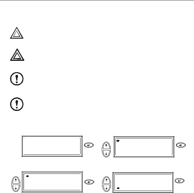
How to turn into bypass
Single System – turning into internal bypass.
The load is not protected by the UPS and the power is not conditioned when the internal mechanical bypass lever is activated.
Caution
In bypass operation the batteries are still charged. If a total power off is required, the batteries must be pulled out to the red disconnect line, see the section How to perform a total power off.
Warning
This procedure is not applicable to parallel systems as the internal mechanical bypass lever is unavailable.
Note
If the UPS is running and controllable through the display, carry out steps 1 through 5. If not, go directly to step 6.
Note
|
|
|
Press |
Use |
Press |
Chrg 100% |
Control |
Logging |
Load 000% |
Status |
Display |
xxxVin 000Vout x0Hz |
Setup |
Diags |
Runtime: 0hr 0m |
|
Help |
|
|
|
|
Use |
Press |
Use |
Press |
UPS into Bypass |
|
Confirm: |
|
Do Self Test |
|
UPS into |
Bypass |
Simulate Power Fail |
|
NO, ABORT |
|
Start Runtime Cal |
|
YES, UPS |
into Bypass |
Check that the UPS is in bypass. The green |
Remove the Front Panel from the UPS (see |
(LOAD ON) and the yellow (BYPASS) LEDs |
the Receiving and Unpacking sheet referred |
are lit. |
to under the section Companion manuals). |
990-2282A-001 |
Smart-UPS® VT 10-40 kVA 400V, 208V, 200V – Operation |
7 |

Operation – Operation Procedures
Turn the internal mechanical bypass lever upwards to activate it. The load
will now be supported directly by
utility/mains power.
Reinstall the Front Panel.
Single System – turning into external bypass.
In bypass operation the batteries are still powered. If a total power off is required the batteries must be pulled out to the red disconnect line, see the section How to perform a total power off.
Warning
|
|
|
Press |
Use |
Press |
Chrg 100% |
Control |
Logging |
Load 000% |
Status |
Display |
xxxVin 000Vout x0Hz |
Setup |
Diags |
Runtime: 0hr 0m |
|
Help |
|
|
|
|
|
Use |
UPS into Bypass |
Press |
Use |
Press |
|
|
Confirm: |
|
|
|
Do Self Test |
|
UPS into |
Bypass |
|
Simulate Power Fail |
|
NO, ABORT |
|
|
Start Runtime Cal |
|
YES, UPS |
into Bypass |
From the external MBP: Turn the bypass |
From the external MBP: Turn the output |
|||
|
switch (Q003) to position “1” (ON). |
|
switch (Q002) to position “0” (OFF). |
|
If the UPS has to be completely isolated/ removed, see the section How to perform a total power off.
8 |
Smart-UPS® VT 10-40 kVA 400V, 208V, 200V – Operation |
990-2282A-001 |
 Loading...