


MGETM GalaxyTM 6000
50, 60 Hz 250 - 600 kVA
"GTC link" communication interface
User manual
6739389EN/FB - Page 1
Page 2 - 6739389EN/FB

Contents
Presentation ...................................................................................................... |
4 |
Introduction ................................................................................................................ |
4 |
"GTCZ" and "GT2Z" boards features ......................................................................... |
4 |
Communication settings ........................................................................... |
5 |
JBUS protocol .................................................................................................. |
6 |
Introduction ................................................................................................................ |
6 |
Principle ..................................................................................................................... |
7 |
Synchronizing data exchanges .................................................................................. |
7 |
Description of request and response frames ............................................................. |
7 |
Checking received messages on the slave-side ........................................................ |
8 |
Functions .................................................................................................................... |
9 |
CRC 16 algorithm .................................................................................................... |
14 |
UPS theory of operation .......................................................................... |
18 |
Unitary UPS ............................................................................................................. |
18 |
Parallel connected UPS with "Static Switch" cubicle ............................................... |
19 |
UPS without Mains 2 ................................................................................................ |
19 |
Unitary UPS ..................................................................................................... |
21 |
Block diagram .......................................................................................................... |
21 |
Measured quantities ................................................................................................. |
21 |
Main status bits ........................................................................................................ |
22 |
Operating modes ..................................................................................................... |
22 |
Parallel connected UPS ........................................................................... |
24 |
Block diagram .......................................................................................................... |
24 |
Measured quantities ................................................................................................. |
24 |
Main status bits of system operations ...................................................................... |
25 |
Operating modes ..................................................................................................... |
25 |
Static switch cubicle .................................................................................. |
26 |
Block diagram .......................................................................................................... |
26 |
Measured quantities ................................................................................................. |
26 |
Main status bits of system operations ...................................................................... |
27 |
Operating modes ..................................................................................................... |
27 |
System information .................................................................................... |
28 |
Message format ....................................................................................................... |
28 |
Example of read data ............................................................................................... |
28 |
Sample commands .................................................................................................. |
28 |
List of variable fields ................................................................................................ |
28 |
General definitions ................................................................................................... |
29 |
Signaling field ........................................................................................................... |
29 |
Tables measured data .............................................................................................. |
29 |
Tables of binary data ................................................................................................ |
31 |
Table of control devices ........................................................................................... |
33 |
Telemonitoring information ....................................................................................... |
33 |
Glossary of information descriptors ......................................................................... |
34 |
Glossary of telemonitoring information descriptors .................................................. |
37 |
All MGETM GalaxyTM 6000 products are protected by patents. They implement original APC by Schneider Electric technology not available to other manufacturers.
This document may be copied only with the written consent of APC by Schneider Electric.
Authorized copies must be marked "APC by Schneider Electric GTC link communication interface user manual No. 6739389EN".
6739389EN/FB - Page 3
Presentation
Introduction
The "GTC link" communication interface is designed to transmit
MGETM GalaxyTM 6000 UPS operating information and remote "on/off" commands (if available) to an external computer.
The JBUS hexadecimal communication protocol is used (the JBUS ASCII mode is not used in this application).
The "GTC link" features two symmetrical communication channels, both with a simplified V24 (RXD and TXD only) and an RS485 interface.
It consists of a "GTCZ" communication board (central unit) and a "RAUZ 1" (communication network management and interconnection board).
In option, two additional communication ports can be added: "GT2Z" board (central unit) and "RAUZ 2" board (communication network management and interconnection board).
Refer to the "communication options connection manual" of
MGETM GalaxyTM 6000 nr 6739388XU, for all informations about connections.
"GTCZ" and "GT2Z" boards features
The "GTCZ" and "GT2Z" boards are functionally divided into two main modules:
The ACQ module
performs data acquisition;
monitors the status bus of the monitor/control boards;
computes physical quantities and battery backup time;
processes alarms;
sends commands to monitor/ control boards;
stores configurable parameters and communicates with the "Soft Tunor" software, used by APC by Schneider Electric after-sales service;
transfers data using the on-board communication channels.
The COM module
The COM communication module is designed for external devices (e.g. "AMUZ" type board of a "Monitor" or "Tele-Monitor") to:
retrieve information and parameters processed by the ACQ;
send commands to monitor/ control boards;
be integrated into other systems (remote indications and supervision).
Each "GTCZ" or "GT2Z" board is equipped with two symmetrical communication ports, COM1 and COM2:
on the "GTCZ" board:
COM1 for a "display devices" network consisting of "AMUZ" boards in a unitary or parallel connected UPS configurations,
COM2 for a supervisory system;
on the "GT2Z" board:
COM1 and COM2 for a supervisory system.
The "GTCZ" and "GT2Z" boards are configured with the APC by Schneider Electric after-sales customization software called "Soft Tunor".
The computer link is via the test connector located on the front panel of the cubicles and performs:
configuration, calibration and control of the ACQ module;
configuration of COM1 and COM2 ports.
Page 4 - 6739389EN/FB
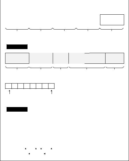
Communication settings
The COM1 and COM2 communication ports can be configured as follows:
data rate: 1200, 2400, 4800, 9600 Baud;
data bits: 8 (always);
parity: none, odd, even;
stop bits: 1 or 2;
|
slave address: 20H to F8H in |
|
command masks; |
|
increments of 8H; |
|
other parameters (modem type, |
||
|
interface: |
telephone number, handshaking, |
||
|
0 |
= RS232 simplified, |
modem protocol, password) |
|
|
1 |
= RS232 complete |
reserved for later use. |
|
(not implemented), |
|
|
||
|
2 |
= RS485; |
|
|
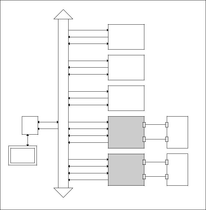
Location of the "GTCZ" and "GT2Z" boards in the cubicle electronics
|
|
Acquisition |
|
|
|
|
Status |
CRIZ |
(only in rectifier-inverter cubicle) |
|
|
|
||
|
|
Test channel |
|
|
|
|
Acquisition |
|
|
|
INTERNAL BUS |
Status |
CROZ |
(only in rectifier-inverter cubicle) |
|
|
|||
|
|
Test channel |
|
|
|
|
Acquisition |
|
|
|
|
Status |
AROZ |
(in all cubicles) |
|
|
|
||
|
|
Test channel |
|
|
|
Test channel |
Acquisition |
|
COM1 |
SRIZ |
|
|
|
|
Status |
Status |
|
|
|
|
|
|
||
|
|
Test channel |
GTCZ |
RAUZ 1 |
|
|
|
|
COM2 |
|
|
Commands |
|
|
Soft Tunor |
|
Acquisition |
|
|
|
|
|
COM1 |
|
|
|
|
|
|
|
|
Status |
|
|
|
|
Test channel |
GT2Z |
RAUZ 2 |
|
|
|
|
COM2 |
|
|
Commands |
|
|
|
|
|
|
6739389EN/FB - Page 5 |
JBUS protocol
Introduction
JBUS protocol can be used to read or write one or more bits or words. In the interest of simplicity, this document describes only the procedures necessary for operation and monitoring of the APC by Schneider Electric unit.
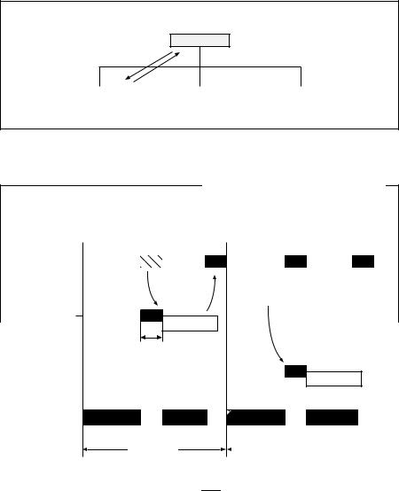
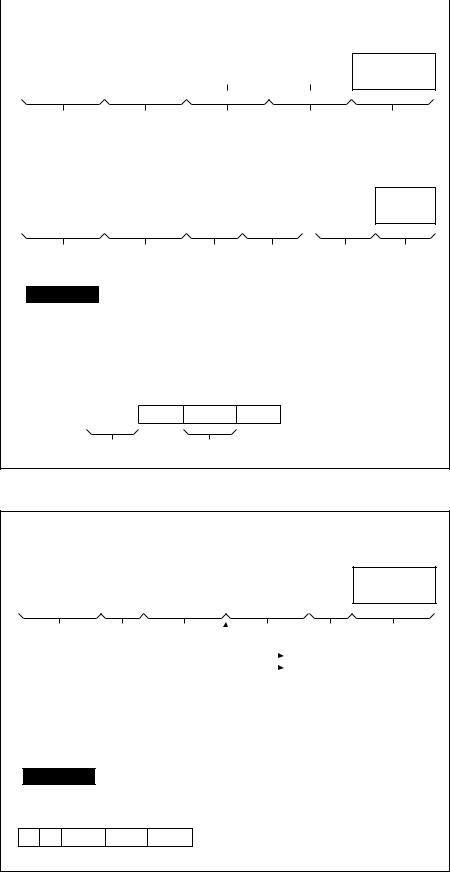
Communications are initiated by the master and include a request from the master and a response from the slave.
Master requests must be addressed to one specific slave (identified by its address in the first byte of the request frame) as shown in the diagram opposite:
Master
request
response
Slave |
|
Slave |
|
Slave |
|
|
|
|
Response |
analysis |
||
|
|
|
|
and preparation |
|||
|
|
|
|
of next exchange |
|||
|
|
|
Wait |
|
|
Wait |
|
MASTER |
|
|
|
|
|
|
|
|
|
request |
|
|
|
request |
|
|
|
|
|
|
|
|
|
|
|
to slave 1 |
|
|
to slave N |
||
SLAVE 1
response
request processing
SLAVE N
response
PHYSICAL
MEDIA
Exchange i |
Exchange i+1 |
Page 6 - 6739389EN/FB
JBUS protocol (continued)
Principle
A full understanding of the protocol is only required if the master is a computer that must be programmed.
All communications include 2 messages: a request from the master and a response from the slave.
Each message or frame containes 4 types of information:
slave address (1 byte)
The slave address specifies the destination station (see address list):
unitary rectifier-inverter cubicle,
parallel rectifier-inverter cubicle,
Static Switch cubicle.
If zero, the request addresses all slaves and there is no response message (in which case it is a broadcast message, a function not used in this application);
function code (1 byte) Selects a command (e.g. read or write a bit or a word) and checks that the response is correct.
The JBUS protocol comprises 10 functions of which 3 may be used in this application: function 3 (read n output or internal words), or function 4 (read n input words), or function 16 (write n words);
information field (n bytes)
The information field contains the parameters related to the functions: bit address, word address, bit value, word value, number of bits, number of words;
check word (2 bytes)
A word used to detect transmission errors.
Synchronizing data exchanges
Any character received after 3 or more character lengths of silence is interpreted as the start of a frame. Therefore, a minimum silence of 3 character lengths between frames must be respected.
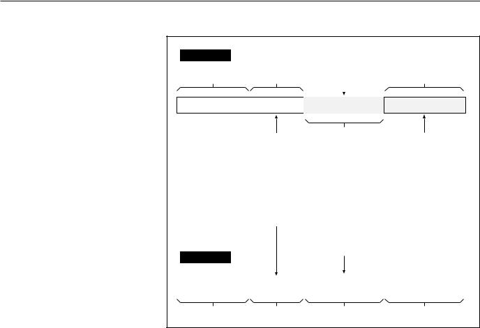
Description of request and response frames
request
information requested: bit/word address, bit/word value, bit/word number.
1 byte |
1 byte |
|
|
|
|
|
|||
|
|
|
|
|
|
|
|
|
|
slave adress |
function |
information |
||
(1 à FF) |
code |
|||
|
|
|||
|
|
|
|
|
n bytes
This function code selects one of 10 possible commands:
-Function 1 : read n output or internal bits
-Function 2 : read n input bits
-Function 3 : read n output or internal words
-Function 4 : read n input words
-Function 5 : write one bit
-Function 6 : write one word
-Function 8 : data exchange diagnostics
-Function 11 : read event counter
-Function 15 : write n bits
-Function 16 : write n words
2 bytes
check word
When the message is received, the slave reads the check word and accepts or refuses the message
values of bits or words read values of bits or words written
number of bits or words
response
slave adress |
function |
data |
CRC |
|
(1 à FF) |
code |
check word |
||
|
||||
1 byte |
1 byte |
bytes |
2 bytes |
6739389EN/FB - Page 7
JBUS protocol (continued)
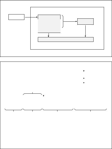
Checking received messages on the slave side
After the master sends a request containing the slave address, the function code and data, it computes the CRC and sends it as the check word (CRC 16).
When the slave receives the request, it stores the message in memory and calculates the CRC 16 to compare it to the received CRC 16.
|
slave |
|
master |
slave address |
|
|
function |
CRC 16 |
|
computation |
|
|
|
|
|
data |
|
|
CRC 16 |
|
|
CRC 16 comparison |
|
If the message is incorrect (unequal CRC 16 values), the slave does not respond.
If the message received is correct but the slave is unable to process it (incorrect address, incorrect data, etc.), the slave returns an error message with the following contents (see opposite):
|
|
|
|
|
Error codes: |
|
|
|
|
|
|
|
response |
|
|
|
|
|
|
|
|
||
|
|
|
|
1. |
Unknown function code |
|
|
|
|
|
|
|
|
|
|
|
|
|
|
|
|||
|
|
|
|
|
2. |
Incorrect address |
|
|
|
|
|
|
|
|
|
|
3. |
Incorrect data |
|
|
|
|
errors handled |
|
|
|
|
|
4. |
Station not ready |
|
|
|
|
|
|
|
|
|
|
|
|
|
|
by the |
||
|
|
|
|
|
|
|
|
|
|||
|
|
|
|
|
8. |
Write error |
|
|
|
|
|
|
|
|
|
|
|
|
|
|
communication |
||
|
|
|
|
|
9. |
Field overlap |
|
|
|
|
|
|
|
function code |
|
|
|
|
|
port |
|||
|
|
|
|
|
|
|
|||||
|
|
|
|
|
|
|
|
|
|||
|
|
|
|
|
|
|
|
|
|
||
|
|
received and |
|
|
|
|
|
|
|
|
|
|
|
MS bit = 1 |
|
|
|
|
|
|
|
|
|
|
|
|
|
|
|
|
|
|
|
|
|
|
|
|
|
|
|
|
|
|
|
|
|
|
slave |
1 |
|
|
|
|
|
|
|
|
CRC 16 |
|
address |
|
|
|
|
|
|
|
|
||
|
(1 à FF) |
|
|
|
|
|
|
|
|
|
|
|
|
|
|
|
|
|
|
|
|
|
|
1 byte |
|
|
|
1 byte |
1 byte |
2 bytes |
|||||
|
|
|
|
|
|
|
|
|
|
|
|
example |
|
|
|
|
|
|
|
|
|
||
|
|
|
|
|
|
|
|
|
|
|
|
|
01 |
09 H |
|
00 |
|
00 |
00 |
00 |
DD CB |
request |
|
|
|
|
|
|
|
|
|
|
|
response |
|
|
|
|
|
|
|
|
|
|
|
||
|
01 |
89 H |
|
01 |
|
86 50 |
|
|
|
||
|
|
|
|
|
|
|
|
|
|
|
|
Page 8 - 6739389EN/FB
JBUS protocol (continued)
Functions |
|
|
|
|
|
|
|
|
|
|
|
||
Function 1 and 2: read N bits |
|
|
|
|
|
|
|
|
|
|
|
||
function 1: read output or internal |
|
|
|
|
|
|
|
|
|
|
|
|
|
|
|
|
|
|
|
|
|
|
|
|
|
||
bits; |
|
|
|
|
|
|
|
|
|
|
|
||
request |
|
|
|
|
|
|
|
|
|
|
|||
function 4: read input bits. |
|
|
|
|
|
|
|
|
|
|
|||
|
|
|
|
|
|
|
|
|
|
|
|||
The number of bits must be less |
|
|
|
|
|
|
|
|
|
|
|
|
|
|
slave address |
|
|
1 or 2 |
|
address of |
number of bits |
CRC 16 |
|
||||
than or equal to the bit field size |
|
|
|
|
|
||||||||
|
|
|
|
first bit |
|
||||||||
|
|
|
|
to read |
|
||||||||
(see memory board). |
|
|
|
|
|
|
MSB LSB |
|
|
||||
|
|
|
|
|
|
|
|
|
|
||||
|
|
|
1 byte |
|
|
|
|
|
|
|
|
|
|
|
|
|
|
|
|
|
|
|
|
|
|
|
|
|
|
|
|
|
1 byte |
|
2 bytes |
2 bytes |
2 bytes |
|
|||
response |
|
|
|
|
|
slave address |
1 or 2 |
number of |
first |
last |
CRC 16 |
bytes |
byte |
byte |
|||
|
|
read |
read |
read |
|
1 byte |
1 byte |
1 byte |
|
bytes |
2 bytes |
byte detail: |
|
|
|
|
|
last bit transmitted |
first bit transmitted |
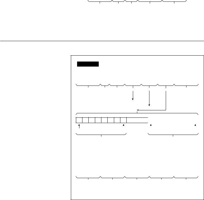
Unused bits are set to zero
example
Reading bits at location 404 to 411 of slave at address 20H (charger signals)
request: |
|
|
|
|
|
|
|
|
|
|
|
|
|
|
||
20 |
01 |
|
0404 |
0E |
|
66 FE |
|
|
|
|
|
|||||
|
|
|
|
|
|
|
|
|
|
|
|
|
|
|
|
|
response: |
|
|
|
|
|
|
|
|
|
|
|
|
|
|
||
|
|
|
|
|
|
|
|
|
|
|
|
|
|
|
||
20 |
01 |
|
02 |
10101001 |
|
00101110 |
FB B7 |
|
||||||||
|
|
|
|
|
|
|
|
|
|
|
|
|
|
|
|
|
|
|
|
|
|
|
|
|
|
|
|
|
|
(binary values) |
|||
|
|
|
|
|
|
|
|
|
|
|
|
|
|
|||
|
|
|
40B |
|
404 411 |
|
40C |
|||||||||
|
|
|
|
|
||||||||||||
6739389EN/FB - Page 9
JBUS protocol (continued)
Function 3 and 4: read N words |
|
|
|
|
|
|
|
|
|
|
|
|
|
|
|
|
|
|
|
|
|
||
|
|
|
|
|
|
|
|
|
|
|
|
|
|
|
|
|
|
|
|
|
|
||
The number of words must be less |
|
|
|
|
|
|
|
|
|
|
|
|
|
|
|
|
|
|
|
|
|
|
|
than or equal to the word field size |
|
|
|
|
|
|
|
|
|
|
|
|
|
|
|
|
|
|
|
|
|
||
request |
|
|
|
|
|
|
|
|
|
|
|
|
|
|
|
|
|
|
|
|
|||
(see memory board). |
|
|
|
|
|
|
|
|
|
|
|
|
|
|
|
|
|
|
|
|
|||
|
|
|
|
|
|
|
|
|
|
|
|
|
|
|
|
|
|
|
|
|
|||
function 3: read output or internal |
|
|
|
|
|
|
|
|
|
|
|
|
|
|
|
|
|
|
|
|
|
|
|
|
slave address |
|
|
3 or 4 |
|
adress of |
|
|
|
|
number of |
|
|
CRC 16 |
|
||||||||
words; |
|
|
|
|
|
|
|
|
|
|
|
||||||||||||
|
|
|
|
first bit |
|
|
|
|
words |
|
|
|
|
|
|
|
|
||||||
function 4: read input words. |
|
|
|
|
|
|
MSB |
LSB |
|
MSB |
|
LSB |
|
|
|
|
|
||||||
|
|
|
1 byte |
|
|
1 byte |
|
2 bytes |
|
|
|
|
|
|
|
|
|
|
|
|
|
|
|
|
|
|
|
|
|
|
|
|
|
|
|
|
|
|
|
|
|
|
|
||||
|
|
|
|
|
|
|
|
|
2 bytes |
2 bytes |
|
||||||||||||
|
|
|
|
|
|
|
|
|
|
|
|
|
|
|
|
|
|
|
|
|
|
|
|
|
|
|
response |
|
|
|
|
|
|
|
|
|
|
|
|
|
|
|
|
|
|
|
|
|
|
|
|
|
|
|
|
|
|
|
|
|
|
|
|
|
|
|
|
|
|
||
|
|
|
slave address |
|
|
3 or 4 |
|
number of |
|
|
first word |
|
last word |
|
|
CRC 16 |
|
||||||
|
|
|
|
|
|
bytes read |
|
|
|
|
|
|
|
|
|
|
|
|
|
|
|||
|
|
|
|
|
|
|
|
|
|
PF |
|
pf |
|
PF |
|
pf |
|
|
|
|
|||
|
|
|
|
|
|
|
|
|
|
|
|
|
|
|
|
|
|
||||||
|
|
|
1 byte |
|
|
1 byte |
|
1 byte |
|
|
2 bytes |
|
2 bytes |
|
|
2 bytes |
|
||||||
|
|
|
|
|
|
|
|
|
|
|
|
||||||||||||
|
|
|
|
|
|
|
|
|
|
|
|
||||||||||||
example
Reading words at location 146 to 14B of slave at address 28H (voltage fields)
request: |
|
|
|
|
|
|
|
|
||
28 |
03 |
|
0146 |
|
06 |
|
A7 E0 |
|
|
|
|
|
|
|
|
|
|
|
|
|
|
response: |
|
|
|
|
|
|
|
|
||
|
|
|
|
|
|
|
|
|
|
|
28 |
03 |
|
0C |
|
XXXX |
|
YYYY |
CRC 16 |
||
|
|
|
|
|
|
|
|
|
||
|
|
|
|
word 0146 |
|
word 014B |
|
|||
Function 5: writing a bit
|
request |
|
|
|
|
|
|
|
|
|
|
|
|
|
|
|
|
|
|
|
|
|
|
|
|
|
|
|
|
|
|
|
slave address |
|
5 |
|
bit address |
bit value |
|
0 |
CRC 16 |
||||||
|
|
|
|
|
|
|
|
|
|
|
|
|
|
|
|
|
|
|
|
|
|
|
|
|
|
|
|
|
|
|
|
|
|
|
|
|
|
|
|
|
|
|
|
|
|
|
|
|
1 byte |
|
1 byte |
|
2 bytes |
|
1 byte |
|
1 byte |
2 bytes |
|||||
|
|
|
|
|
|||||||||||
|
|
|
|
|
|
|
|
|
|
|
write 0 |
|
|||
|
|
|
|
|
|
bit set to 0 |
|
|
|
||||||
|
|
|
|
|
|
|
|
||||||||
|
|
|
|
|
|
bit set to 1 |
|
|
write FF |
|
|||||
|
|
|
|
|
|
|
|
||||||||
|
response |
|
|
|
|
|
|
|
|
|
|
|
|
|
|
|
|
|
|
|
|
|
|
|
|
|
|||||
|
slave address |
|
5 |
|
bit address |
bit value |
|
0 |
CRC 16 |
||||||
|
|
|
|
|
|
|
|
|
|
|
|
|
|
|
|
In function 5 the response and request frames are identical.
example
Setting bit location C05 to 1 of slave at address 40H (inverter on)
request:
40 05 0C05 FF  00 90 7A
Page 10 - 6739389EN/FB
JBUS protocol (continued)
Function 6: writing a word
|
request |
|
|
|
|
|
|
|
|
|
|
|
|
|
|
|
|
|
|
|
|
|
slave address |
|
6 |
|
word address |
word |
CRC 16 |
|||
|
|
|
|
|
|
|
|
|
|
|
|
|
|
|
|
|
|
|
|
|
|
|
|
|
|
|
|
|
|
|
|
|
|
|
|
|
|
|
|
|
|
|
|
|
1 byte |
|
|
1 byte |
|
2 bytes |
2 bytes |
2 bytes |
||
|
|
|
|
|
|
|
|
|
|
|
|
response |
|
|
|
|
|
|
|
|
|
|
|
|
|
|
|
|
||||
|
slave address |
|
6 |
|
word address |
word |
CRC 16 |
|||
|
|
|
|
|
|
|
|
|
|
|
|
|
|
|
|
|
|
|
|
|
|
The response is echoed acknowledging that the word sent has been received.
example
Writing the value 1000 into the word location 810H of slave at address 50H
50 |
06 |
08 10 |
10 00 |
8A 2E |
|
|
|
|
|
Function 8: reading error diagnosis counters
Each slave manages a set of nine 16 bit counters for error diagnosis (see opposite):
- request / response:
slave address |
8 |
|
sub-function |
data |
|
CRC 16 |
|
|
code |
|
|||||
|
|
|
|
|
|
|
|
|
|
|
|
|
|
|
|
|
|
|
|
|
|
|
|
|
|
|
|
|
|
|
|
1 byte |
1 byte |
2 bytes |
-the slave must echo the request
-reset error diagnosis counter
-read the total number of:
received frames with CRC error (CNT 1)
received frames with CRC error (CNT 2)
number of exception responses (CNT 3)
frames addressed to the station (CNT 4) (not including broadcast)
broadcast requests received (CNT 5)
number of NACK responses (CNT 6) unit not ready responses (CNT 7)
illegal characters (CNT 8)
|
|
2 bytes |
2 bytes |
||
|
|
|
|
|
|
|
|
|
|
|
|
00 |
XYZT |
X, Y, Z, T are user |
|||
|
|
|
|
defined (transmission |
|
|
|
|
|
parameters) |
|
0A |
0000 |
|
|||
0B |
XXXX |
|
|||
0C |
XXXX |
|
|||
0D |
XXXX |
requests: |
|||
|
|
|
|
||
0E |
XXXX |
XXXX equals 0000 |
|||
response: |
|||||
|
|
|
|
||
0F |
XXXX |
XXXX is the counter |
|||
value |
|||||
|
|
|
|
||
10XXXX
11XXXX
12XXXX
6739389EN/FB - Page 11
JBUS protocol (continued)
Function 11: reading event counters
The master and each slave have one event counter.
This counter is incremented each time a frame is received and interpreted correctly by the slave (except for function 11 itself).
A correctly transmitted message increments the counter. If the slave sends an exception response, the counter is not incremented.
The master can read the counter to determine whether or not the slave correctly interpreted the command (incremented the counter or not).
These functions can be used to diagnose the data exchange taking place between master and slaves.
|
|
|
|
|
|
|
|
|
|
|
|
|
|
|
|
request |
|
|
|
|
|
|
|
|
|
|
|
|
|
|
|
|
|
|
|
|
|
|
||||||
|
slave address |
|
|
0B |
|
CRC 16 |
|
|
|
|||||
|
|
|
|
|
|
|
|
|
|
|
|
|
|
|
|
|
|
|
|
|
|
|
|
|
|
|
|
|
|
|
response |
|
|
|
|
|
|
|
|
|
|
|
|
|
|
|
|
|
|
|
|
|
|
|
|
|
|
|
|
|
slave address |
|
|
0B |
|
|
0 |
|
slave |
|
CRC 16 |
|
||
|
|
|
|
|
counter word |
|
|
|
||||||
|
|
|
|
|
|
|
|
|
|
|
|
|||
|
|
|
|
|
|
|
|
|
|
|
|
|
|
|
|
|
|
|
|
|
|
|
|
|
|
|
|
|
|
|
|
|
|
|
|
|
|
|
|
|
|
|
|
|
|
1 byte |
|
|
1 byte |
2 bytes |
|
2 bytes |
2 bytes |
||||||
|
|
|
|
|
|
|
|
|
|
|
|
|
|
|
If the master counter equals the |
|
|
If the master counter is one higher |
|||||||||||
slave counter, the slave executed |
|
than the slave counter, the slave |
||||||||||||
the command sent by the master. |
|
did not execute the command sent |
||||||||||||
|
|
|
|
|
|
|
|
|
by the master. |
|
|
|||
Function 15: writing n consecutive bits
request
|
slave adress |
|
0F |
|
address of |
|
|
|
number |
|
|
number |
|
|
bit data |
|
|
CRC 16 |
|
||||||||||||||||
|
|
|
the first bit |
|
|
|
of bits |
|
|
of bytes |
|
|
|
|
|
||||||||||||||||||||
|
|
|
|
|
|
|
|
|
|
|
|
|
|
|
|
|
|
|
|
|
|
|
|||||||||||||
|
|
|
|
|
|
|
|
|
|
|
|
|
|
|
|
|
|
|
|
|
|
|
|
|
|
|
|
|
|
|
|
|
|
|
|
|
|
|
|
|
|
|
|
|
|
|
|
|
|
|
|
|
|
|
|
|
|
|
|
|
|
|
|
|
|
|
|
|
|
||
|
|
|
|
|
|
|
|
|
|
|
|
|
|
|
|
|
|
|
|
|
|
|
|
|
|
|
|
|
|
|
|
|
|
|
|
|
|
|
|
|
|
|
|
|
|
||||||||||||||||||||||||||
|
1 byte |
1 byte 2 bytes |
|
2 bytes |
|
1 byte |
|
|
|
2 bytes |
|||||||||||||||||||||||||
|
|
|
|
|
|
|
|
n bytes |
|||||||||||||||||||||||||||
|
|
|
|
|
|
|
|
|
|
|
|
|
|
|
|
|
|
|
|
|
|
|
|
|
|
|
|
|
|
|
|
|
|
|
|
|
réponse |
|
|
|
|
|
|
|
|
2 X 1968 |
|
|
|
|
|
|
|
|
|
|
|
|
|
|
|
|
|
|
|
|
|||||
|
|
|
|
|
|
|
|
|
|
|
|
|
|
|
|
|
|
|
|
|
|
|
|
|
|
|
|
|
|||||||
|
|
|
|
|
|
|
|
|
|
|
|
|
|
|
|
|
|
|
|
|
|
|
|
|
|
|
|
|
|
|
|
|
|
||
|
|
|
|
|
|
|
|
|
|
|
|
|
|
|
1 N 246 |
|
|
|
|
|
|
|
|
|
|
||||||||||
|
|
|
|
|
|
|
|
|
|
|
|
|
|
|
|
|
|
|
|
|
|
|
|
|
|
|
|
|
|
|
|
|
|||
|
|
|
|
|
|
|
first bit |
|
|
|
|
|
|
|
|
|
|
|
|
|
|
|
|
|
|
|
|
|
|
|
|
|
|
|
|
|
last bit of |
|
|
|
|
|
|
|
|
|
|
|
|
|
|
|
|
|
last bit of |
|
|
|
|
|
|||||||||||
|
|
|
|
|
|
|
|
|
|
|
|
|
|
|
|
|
|
||||||||||||||||||
|
|
|
|
of |
|
|
|
|
|
|
|
|
first bit of |
||||||||||||||||||||||
|
first byte |
|
|
|
|
first byte |
|
|
|
|
|
|
|
byte N |
|
|
|
|
|
byte N |
|||||||||||||||
|
first byte |
|
|
|
|
|
|
|
|
|
|
|
|
|
|
|
|
N bytes |
|
|
|
|
|
||||||||||||
|
|
|
|
|
|
|
|
|
|
|
|
|
|
|
|
|
|
|
|
|
|
|
|
|
|
|
|
|
|
|
|
|
|
|
|
|
response |
|
|
|
|
|
|
|
|
|
|
|
|
|
|
|
|
|
|
|
|
|
|
|
|
|
|
|
|
|
|
|
|
|
|
|
|
|
|
|
|
|
|
|
|
|
|
|
|
|
|
|
|
|
|
|
|
|
|
|
|
|
|
|
|
|
|
|
|||
|
slave address |
|
|
|
|
0F |
|
|
address of |
|
|
|
|
|
number of bits |
|
CRC 16 |
|
|||||||||||||||||
|
|
|
|
|
|
|
|
|
|
|
|
the first bit |
|
|
|
|
|
|
|
|
|
|
|
|
|
|
|
|
|
|
|
|
|||
|
|
|
|
|
|
|
|
|
|
|
|
|
|
|
|
|
|
|
|
|
|
|
|
|
|
|
|
|
|
|
|
|
|||
|
|
|
|
|
|
|
|
|
|
|
|
|
|
|
|
|
|
|
|
|
|
|
|
||||||||||||
|
|
|
|
|
|
|
|
|
|
|
|
|
|
|
|
|
|
|
|
|
|
|
|
|
|
||||||||||
|
1 byte |
|
|
1 byte |
|
2 bytes |
|
|
|
|
|
|
|
2 bytes |
2 bytes |
||||||||||||||||||||
|
|
|
|
|
|
|
|
|
|
|
|
|
|
|
|
|
|
|
|
|
|
1 X |
1968 |
|
|
|
|
|
|
|
|
||||
Note: if the slave address is 0, all units execute the write command without sending a response.
Page 12 - 6739389EN/FB
 Loading...