


®
Back-UPS® ES 350/550
www.apc.com |
User Guide |
|
Connect Battery
1For safety, the Back-UPS ES is shipped with one battery wire disconnected. The Back-UPS ES will not operate until the wire is connected to the touch safe battery terminal. NOTE: Small sparks may occur during battery connection. This is normal.
1 |
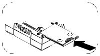
TURN the Back-UPS ES over and |
slide the battery compartment |
cover off of the battery housing.
2 |
LIFT the battery out of the compartment and connect the black wire to the negative (-) battery |
terminal. Ensure the batteries are installed as shown below. |
Slide the battery compartment cover 3 completely onto the Back-UPS ES.
Back-UPS ES 350 |
Back-UPS ES 550 |


 2
2
Battery Backup  Surge Protection
These outlets are powered whenever the Back-UPS ES is switched ON. During a power outage or other utility problems
Connect Equipment
Place the Back-UPS ES to avoid:
- Direct sunlight - Excessive heat - Excessive humidity or contact with fluids
Plug the Back-UPS ES power cord directly into a wall outlet; not a surge protector or power strip.
(brownouts, over-voltages), these outlets will be powered for a limited time by the Back-UPS ES. Plug your computer, monitor, and two other data-sensitive devices (external disk or tape drive) into these outlets.
® |
|
|
|
|
|
|
|
|
|
|
|
|
|
|
|
|
|
|
|
|
|
|
|
w w w.apc.com |
|
|
|
|
|
|
|
|
AC LINE |
||||||||||||||
|
|
|
|
|
|
|
|
|
|
|
|
|
|
|
|
|
|
|
|
|
CORD |
||
|
|
|
|
|
Battery Backup |
Surge Protection |
|
|
|
|
|
|
|||||||||||
|
|
|
|
|
|
|
|
|
|
|
|
|
|
|
|
|
|
|
|
|
|
|
|
|
|
|
|
|
|
|
|
|
|
|
|
|
|
|
|
|
|
|
|
|
|
|
|
|
|
|
|
|
|
|
|
|
|
|
|
|
|
|
|
|
|
|
|
|
|
|
|
Connect FAX/Modem/Phone
Back-UPS ES protects a single line (2-wire) fax, modem or phone from surges when it is connected through the Back-UPS ES as shown.
Connect Computer Cable
The supplied cable and software provide automatic file saving and shutdown of the operating system in the case of a sustained power outage.
Connect the cable to the Data Port of the Back-UPS ES. Connect the other end of the cable to the USB port on your computer. The software will automatically find the USB Port of your computer.
|
Surge Protection Only |
|
|
|
POWER ON/ |
Back-UPS ES |
BUILDING WIRING |
|
|
5 5 0 |
|
|
||
|
|
|
|
|
REPLACE BATTERY |
|
FAULT INDICATOR |
Wiring |
CAUTION - Refer to bottom |
INDICATOR |
Replace Battery |
|
||
|
Power On |
|
Building |
|
|
|
FROM WALL JACK |
Fault |
of unit for safety markings. |
|
|
Wall |
||
|
|
Push to Reset |
||
|
|
|
|
Circut Breaker |
|
|
|
Outlet |
|
|
|
DATALINE OUTPUT TO |
Phone/Fax |
|
|
|
DSL MODEM or PHONE |
Modem/ |
|
|
|
|
|
|
|
|
|
Data Port |
|
Surge Protection Only |
TO COMPUTER |
CIRCUIT BREAKER |
||
These outlets provide full-time protection from surges even if |
USB PORT |
PUSH TO RESET |
||
|
|
|
||
the Back-UPS ES is switched OFF. Plug your printer, fax |
|
|
|
|
machine, scanner, or other peripherals that do not need |
|
|
|
|
battery power into these outlets. |
|
|
|
|
3Power On and
Install Software
Press the ON/OFF switch to power the unit ON.
A single short beep and the green “Power On” indicator confirms that Back-UPS ES is on and ready to provide protection.
The Back-UPS ES should charge for at least 16 hours to ensure sufficient runtime. The unit is being charged whenever it is connected to utility power, whether the unit is turned ON or OFF.
If the red Building Wiring Fault indicator (located on the end near the power cord) is lit, your building wiring presents a shock hazard that should be corrected by a qualified electrician.
Install the PowerChute Personal® Edition software
Place the PowerChute Personal Edition CDROM into your computer and follow the installation instructions on the screen.
Status |
Visual Indications |
Audible Indication |
Alarm Terminates |
|
|
(Power On - Green) |
|
When |
|
|
(Replace Battery - Red) |
|
|
|
|
|
|
|
|
Power On - UPS is supplying conditioned |
Power On LED - ON |
None |
Not applicable. |
|
utility power to the load. |
|
|
|
|
|
|
|
|
|
On Battery - UPS is supplying battery |
Power On LED |
- ON (off |
Beeping 4 times every |
UPS transfers back to |
power to the load connected to the Battery |
during beep) |
|
30 seconds |
Power On operation, or |
outlets. |
|
|
|
when UPS is turned off. |
|
|
|
|
|
Low Battery Warning - UPS is supplying |
Power on LED |
- flashing |
Rapid beeping (every |
UPS transfers back to |
battery power to the load connected to the |
|
|
1/2 second) |
normal operation, or |
Battery outlets and the battery is near |
|
|
|
when UPS is turned off. |
exhaustion. |
|
|
|
|
|
|
|
|
|
Replace Battery - The battery is |
Replace Battery LED - |
Constant tone |
UPS turned off with the |
|
disconnected. |
flashing |
|
|
power switch. |
The battery is in need of charging or is at |
Power On and Replace |
Constant tone |
|
|
the end of its usual life and must be |
Battery LEDs- |
Flashing |
|
|
replaced. |
(alternating) |
|
|
|
|
|
|
|
|
Overload Shutdown - During On Battery |
None |
|
Constant tone |
UPS turned off with the |
operation a battery power supplied outlet |
|
|
|
power switch. |
overload was detected. |
|
|
|
|
|
|
|
|
|
Sleep Mode - During On Battery operation |
None |
|
Beeping once every 4 |
Utility power is restored, |
the battery power has been completely |
|
|
seconds |
or if utility power is not |
exhausted and the UPS is waiting for utility |
|
|
|
restored within 32 |
power to return to normal. |
|
|
|
seconds, or the UPS is |
|
|
|
|
turned off. |
|
|
|
|
|
Building Wiring Fault - Your building |
Building Wiring Fault LED |
None |
UPS is unplugged, or is |
|
wiring presents a shock hazard that should |
(red) - ON |
|
|
plugged into a properly |
be corrected by a licensed electrician. |
|
|
|
wired outlet. |
|
|
|
|
|
See the Troubleshooting section for additional assistance.
990-4993A Copyright 2006 American Power Conversion Corporation |
APC, the APC logo, Back-UPS and PowerChute are registered trademarks of American Power Conversion Corp. |
|
All other trademarks are property of their respective owners. |
 Loading...