


GPVT 40
A.O. Smith GPVT 40, GPVT 50, GPVL-40, GPVT-40 LP, GPVL-50 LP Technical Documents
...
Service Handbook
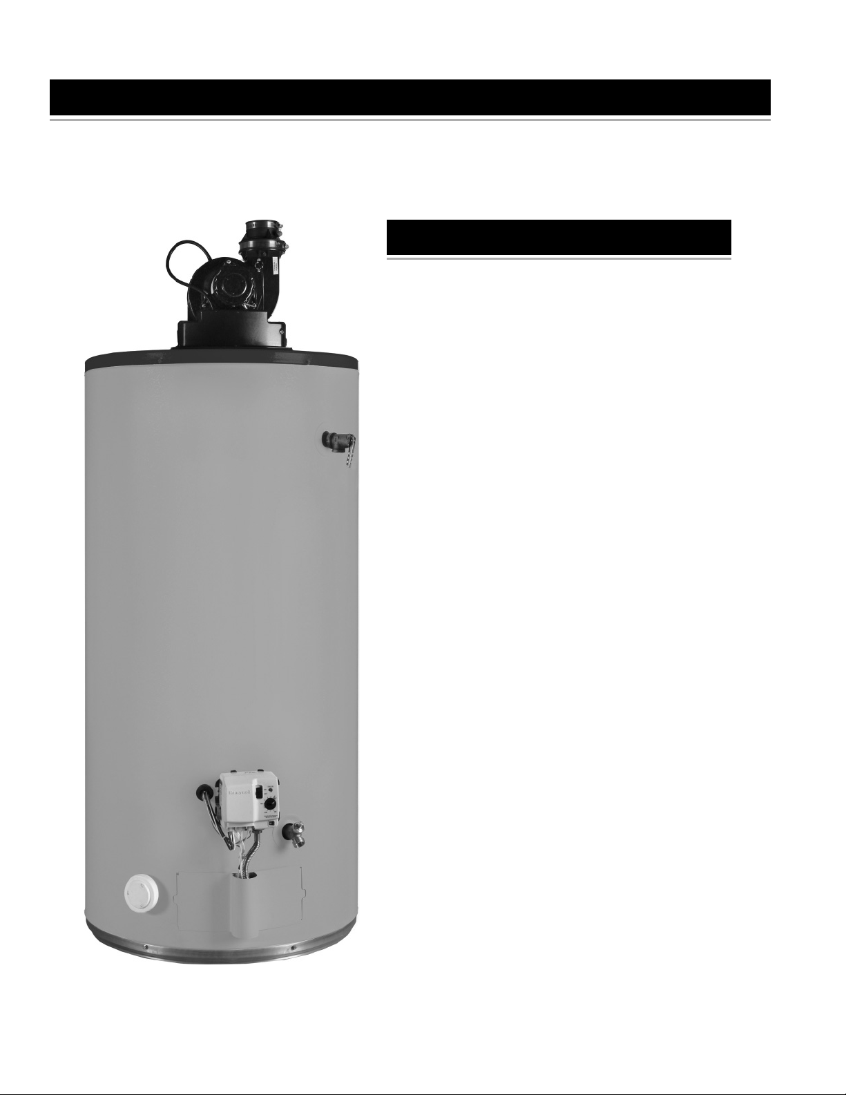
RESIDENTIAL GAS WATER HEATERS
POWER VENTED GAS MODELS
WITH HOT SURFACE IGNITION
NOT FOR USE IN MANUFACTURED (MOBILE) HOMES
TABLE OF CONTENTS
GENERAL INFORMATION 2
CHECKING THE GAS SUPPLY PRESSURE 3
LEAKAGE CHECKPOINTS 4
TEMPERATURE ADJUSTMENT 5
ANODE ROD REMOVAL/REPLACEMENT 6
DIP TUBE REMOVAL/REPLACEMENT 7
DOOR-BURNER ASSEMBLY REMOVAL/
REPLACEMENT 8
FLAME SENSOR AND IGNITER REMOVAL/
REPLACEMENT 10
BURNER AND ORIFICE REMOVAL/
REPLACEMENT 12
DOOR GASKET REPLACEMENT 16
CONTROL MODULE REMOVAL/REPLACEMENT 18
VALVE MODULE REMOVAL/REPLACEMENT 20
TEMPERATURE SENSOR AND CABLE REMOVAL/
REPLACEMENT 21
GAS VALVE REMOVAL/REPLACEMENT 22
BLOWER REMOVAL/REPLACEMENT 24
ROTATING THE BLOWER 25
PRESSURE SWITCH REMOVAL/REPLACEMENT 26
FV SENSOR 27
CLEANING THE COMBUSTION CHAMBER 28
CLEANING THE BLOWER 29
TECHNICAL BULLETINS 30
TROUBLESHOTING CHART 36
Note: References to the Manual refer to the “Installation
and Operating Manual”.
1206 322153-000 Rev. 00

GENERAL INFORMATION
Draw effi ciency is the quantity of hot water available to the
consumer before the outlet water temperature decreases
by 25F° (14C°). A 40 gallon water heater will typically
provide 70% (28 gallons) of this “usable” hot water (60%
is the minimum). The burner or elements are allowed to
operate during this test. Incoming, cold water mixes the
remaining stored water below this 25F° (14C°) limitation.
Energy Factor is an indicator of the combined thermal
effi ciency and standby effi ciency of a water heater. The
higher the energy factor, the more effi cient the water
heater will be.
Minerals and gases will separate from water as
temperature increases.
“R” Value is a measure of the resistance of a substance
to heat fl ow.
Recovery rate is the amount of water that is heated to a
set temperature, per hour.
Standby effi ciency is the water heater’s ability to contain
heat in the tank. A minimum of tank water heat loss per
hour is desired. e.g. temperature change/“R” value = Btu/h
loss/square foot of tank surface
Temperature rise is the increase in the temperature from
its coldest “inlet” water temperature to the desired hot
(outlet) setting. Typically it is assumed that the entering
water be 40°F (5°C), stored water desired to be 120°F
(49°C) resulting in a “temperature rise” of 80F° (44C°).
Thermal efficiency is approximately the amount of
generated BTU (British Thermal Units), which enters the
water. A percentage of the total BTU passes out through
the vent piping.
Water cannot (for all practical purposes) be
compressed.
Water expands when it is heated.
Formulas and Conversions:
BTU (British Thermal Unit) is the heat required to raise 1
pound of water 1F°
1 BTU = 252 cal = 0.252 kcal
1 cal = 4.187 Joules
BTU X 1.055 = Kilo Joules
BTU divided by 3,413 = Kilowatts
To convert from Fahrenheit to Centigrade: (°F – 32) times
5/9, or .556, equals degrees C.
One gallon of (120°F, 49°C) water weighs approximately
8.25 pounds.
Pounds X .45359 = Kilogram
Gallons X 3.7854 = Liters
% of Hot = (Mixed Temp. – Cold) divided by (Hot Temp.
– Cold)
% Thermal Effi ciency = (GPH X 8.25 X Temp. Rise X 1.0)
divided by BTU/H Input
BTU Output = GPH X 8.25 X Temp. Rise X 1.0
GPH = (BTU/H Input X % Eff.) divided by (Temp. Rise X
8.25)
One cubic foot of Natural Gas contains about 1000 BTU
of heat.
One “therm” is equal to 100,000 BTU
One cubic foot of Propane Gas contains about 2500 BTU
of heat.
One gallon of Propane gas contains about 91,250 BTU
of heat.
One pound of Propane gas contains about 21,600 BTU
of heat.
One pound of gas pressure is equal to 27.7 inches water
column pressure
Inches of Water Column X .036091 = PSI
Inches of Water Column X .073483 = Inches of Mercury
(Hg.)
Centimeters = Inches X 2.54
mm (millimeters) = Inches X 25.4
Meters = Inches X .0254
Doubling the diameter of a pipe will increase its fl ow
capacity (approximately) 5.3 times.
Construction: Tank is constructed of steel. The inside of the
tank is constructed of a glass lining bonded to the steel.
This prevents water to metal contact and rusting of the
tank. An anode rod will be installed within the tank. The
hex-head plug end of the anode is visible on the top of the
water heater. This metal rod offers secondary protection of
the tank against corrosion where the application of glass
is not possible (threaded tank openings). These areas will
have small areas of water to metal contact.
All water heaters will contain at least one thermostat (to
operate the heater) and one high limit (to prevent water
from overheating).
2
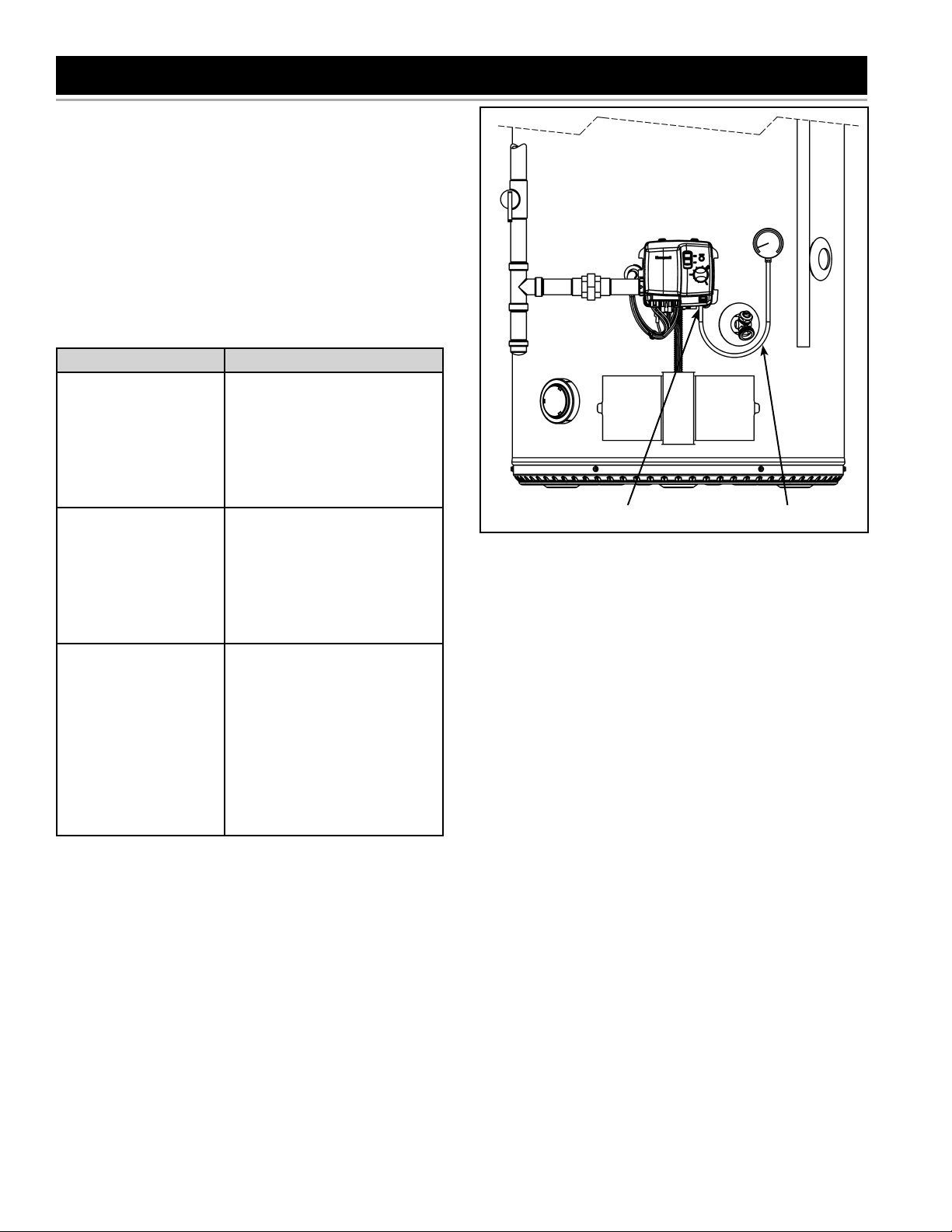
CHECKING THE GAS SUPPLY PRESSURE
Gas pressure checks are done with fl owing gas using a
gas pressure manometer capable of reading pressure in
inches of water column.
Supply gas pressure checks are measured before the gas
control valve and as close to the water heater as possible.
Manifold (main burner) gas pressure is measured at the
pressure tap on the bottom of the gas control valve (see
Figure 1). Use an allen wrench to remove the plug, then
attach the gas gauge.
Note: Desired gas pressures will be noted on the gas valve
label located on the gas control valve and rating plate.
IF THEN
Supply gas pressure
is under desired
pressure requirement
Supply gas pressure
is over desired
pressure
Manifold gas pressure
is more than +/- .4
inch W.C. from values
indicated on gas valve
or rating plate
Increase supply gas
•
pressure regulator setting.
Call the gas utility company
•
to readjust gas pressure on
main supply. Technicians
can not adjust main gas
supply pressure.
Add gas pressure
•
regulator.
Call the gas utility company
•
to readjust gas pressure on
main supply. Technicians
can not adjust main gas
supply pressure.
Ensure there is adequate
•
supply gas pressure.
Ensure the main burner
•
orifice is the correct size
for the water heater model
being tested.
If the above tests have been
•
performed and the results
were correct replace the
gas control valve.
MANIFOLD (MAIN BURNER GAS PRESSURE
TAP). RE-INSTALL PLUG AFTER USE.
Figure 1
PRESSURE
MANOMETER
Important: After checking the manifold gas pressure,
detach the gas gauge, reinstall the plug using insulation
tape and tighten with allen wrench. Check for leaks and
repair as required.
3
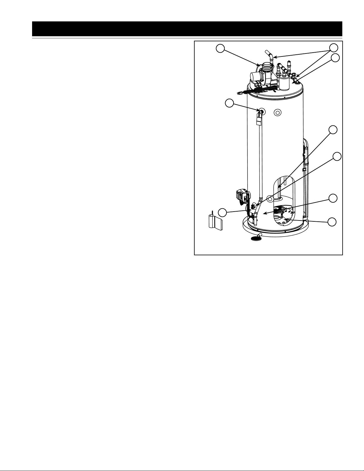
LEAKAGE CHECKPOINTS
A. Water at the blower assembly is water vapor which
has condensed out of the combustion products. This
is caused by a problem in the vent or blockage in the
drain coupling.
B. Condensation may be seen on pipes in humid weather
or pipe connections may be leaking.
C. The anode rod fi tting may be leaking.
D. Small amounts of water from temperature-pressure
relief valve may be due to thermal expansion or high
water pressure in your area.
E. *The temperature-pressure relief valve may be leaking
at the tank fi tting.
F. Water from a drain valve may be due to the valve being
slightly opened.
G. The drain valve may be leaking at the tank fi tting.
H. Combustion products contain water vapor which can
condense on the cooler surfaces of the tank. Droplets
form and drip onto the burner. This is common at the
time of start-up after installation and when incoming
water is cold.
I. Water in the water heater bottom or on the fl oor may be
from condensation. DO NOT replace the water heater
until a full inspection of all possible water sources is
made and necessary corrective steps taken.
J. Leakage from other appliances, water lines, or ground
seepage should also be checked.
A
B
C
E
H
G
D
F
I
* To check where threaded portion enters tank, insert
cotton swab between jacket opening and fi tting. If cotton
is wet, follow draining instructions in the “Draining
and Flushing” section in the Manual and then remove
fi tting. Put pipe dope or Tefl on® tape on the threads
and replace. When you are fi nished, follow the steps
in “Filling the Water Heater” section in the Manual.
Figure 2
4
TEMPERATURE ADJUSTMENT
Safety
Due to the nature of the typical gas water heater, the
water temperature in certain situations may vary up to
30F° (16C°) higher or lower at the point of use such as
bathtubs, showers, sink, etc.
HOT WATER CAN SCALD: Water heaters are intended to
produce hot water. Water heated to a temperature which
will satisfy space heating, clothes washing, dish washing,
and other sanitizing needs can scald and permanently
injure you upon contact. Some people are more likely to
be permanently injured by hot water than others. These
include the elderly, children, the infi rm, or physically/
mentally handicapped. If anyone using hot water in your
home fi ts into one of these groups or if there is a local code
or state law requiring certain temperature water at the hot
water tap, then you must take special precautions.
In addition of using the lowest possible temperature setting
that satisfi es your hot water needs, a means such as a
mixing valve should be used at the hot water taps used
by these people or at the water heater. Mixing valves are
available at plumbing supply or hardware stores. Follow
manufacturer’s instructions for installation of the valves.
Using the lowest hot water temperature that meets your
needs will also provide the most energy effi cient operation
of the water heater.
Never allow small children to use a hot water tap, or to draw
their own bath water. Never leave a child or handicapped
person unattended in a bathtub or shower.
Note: A water temperature range of 120°F-140°F
(49°C-60°C) is recommended by most dishwasher
manufacturers.
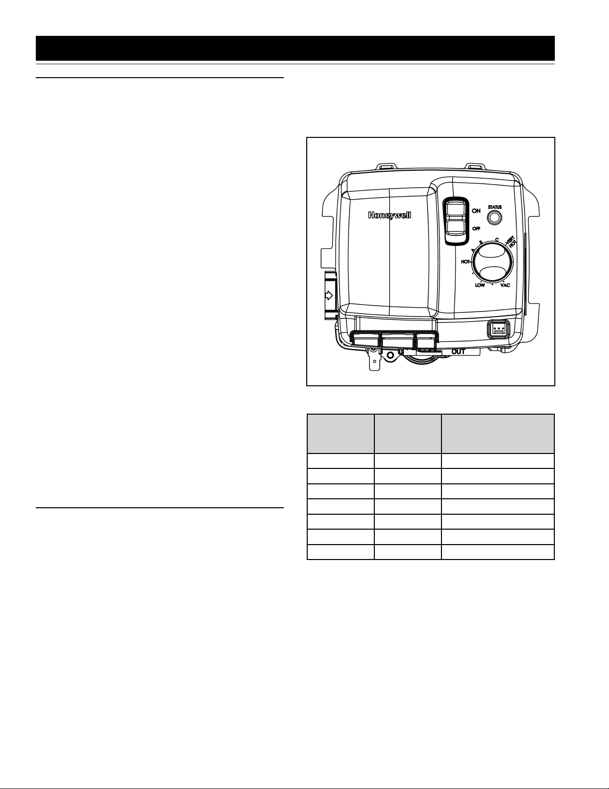
Settings
Temperature range on residential gas water heater is from
110°F ±10° to 155°F ±10° and a 70°F vacation setting. The
T&P valve will open at 195°F ± 10°.
The water heater temperature adjusting dial (see Figure
3) was factory set at the lowest temperature; all the way
counter-clockwise to the mechanical stop, unless specifi ed
differently by provincial or state regulations. It is adjustable
and must be reset to the desired temperature setting to
reduce the risk of scald injury. Turning the dial clockwise
will increase the temperature and counter-clockwise
will reduce the temperature. The HOT marking on the
Honeywell gas valve is indicative of approximately 120°F
(49°C) and is the preferred starting point. Some states
have a requirement for a lower setting. Should overheating
occur or the gas supply fails to shut off, turn “OFF” the
manual gas control valve to the water heater.
temperatures at the point of use to exceed the thermostat
setting by up to 30F° (16C°). If you experience this type of
use, you should consider using lower temperature settings
to reduce scald hazards. Listed below is time-to-burn
relationship for normal adult skin.
Figure 3
Temperature
Setting
VERY HOT 155 (68) Less than 1 second
C 150 (65) About 1.5 seconds
B 140 (60) Less than 5 seconds
A 130 (54) More than 30 seconds
HOT 120 (49) More than 5 minutes
LOW 110 (43) Normal shower temp
VAC 70 (21) N/A
Approximate
Temperature
°F (°C)
Table 1
Time to reduce a 2nd
and 3rd Degree burn
to adult skin
The following table lists the approximate water temperatures
produced by various dial settings. Short repeated heating
cycles caused by small hot water uses can cause
5
ANODE ROD REMOVAL/REPLACEMENT
ANODE ROD
Important: Use only factory authorized replacement parts.
If you lack the necessary skills to properly perform the
installation, you should not proceed, but get help from a
qualifi ed service technician.
Tools required:
•
Ratchet with 1-1/16” Socket
•
Pliers
®
•
Te fl on
Tape or an approved pipe sealant
Removing Anode Rod:
Set the gas control valve/thermostat to its lowest
1.
setting by turning the knob counter-clockwise to the
VAC point (see Figure 3).
Turn gas control switch to the “OFF” position and turn
2.
“OFF” the gas supply to the unit (see Figure 3).
Disconnect the electrical power to the water heater
3.
from the wall outlet.
Shut off the incoming water supply to the water heater
4.
and open a nearby hot-water faucet to depressurize
the water tank.
Connect a hose to the drain valve and terminate it to
5.
adequate drain or to the exterior of the building. Open
the drain valve and allow at least 5 gallons of water to
drain from the tank. Close drain and remove hose.
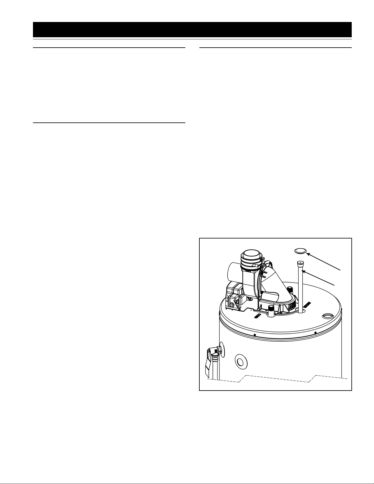
Remove and retain the anode cap on top of the heater
6.
and remove and retain just enough insulation so you
can access to the anode head (see Figure 4). Keep in
a safe place for reinstallation later.
Remove the anode rod by using a ratchet and a 1-1/16”
7.
socket turning counter-clockwise (see Figure 4).
Installing Anode Rod:
1.
Use Tefl on
®
tape or an approved pipe sealant on
threads of the new anode rod.
2.
Place the anode rod in the spud (top of the tank) and
turn clockwise until the threads are hand tight. Using a
ratchet and 1-1/16” socket tighten down water tight.
3.
Turn the main water supply back on.
4.
Open a nearby hot-water faucet to purge air from the
water line. Fill water heater tank completely (Note: To
assure the water heater tank is full, keep the hot-water
faucet open for 3 minutes after a constant fl ow of water
is obtained).
5.
After turning off the hot-water faucet, check for water
leaks around anode rod and immediately correct any
if found.
6.
Reinstall the insulation and anode cap which were
removed in step 6 above.
7.
Reconnect the electrical power to the water heater in
the wall outlet and turn the main gas supply back “ON”
to the gas control valve/thermostat.
8.
Turn the gas control switch to the “ON” position (see
Figure 3).
9.
To restart the water heater, follow the directions on
the “Lighting and Operating Instructions” label located
on the front of the water heater near the gas control
valve/thermostat.
CAP
* THE ANODE ROD IS COVERED
BY URETHANE FOAM LOCATED
UNDER THE CAP. CHIP AWAY
THE FOAM TO EXPOSE THE
TOP OF THE ANODE ROD
Figure 4
ANODE ROD *
6
DIP TUBE REMOVAL/REPLACEMENT
DIP TUBE
Important: Use only factory authorized replacement parts.
If you lack the necessary skills to properly perform the
installation, you should not proceed, but get help from a
qualifi ed service technician.
Tools required:
•
18” Pipe wrench
•
Piping and soldering equipment
®
•
Te fl on
Removing Dip Tube:
1.
2.
3.
4.
5.
6.
7.
Tape or an approved pipe sealant
Set the gas control valve/thermostat to its lowest
setting by turning the knob counter-clockwise to the
VAC point (see Figure 3).
Turn gas control switch to the “OFF” position and turn
“OFF” the gas supply to the unit (see Figure 3).
Disconnect the electrical power to the water heater
from the wall outlet.
Shut off the incoming water supply to the water heater
and open a nearby hot-water faucet to depressurize
the water tank. Remove pipe insulation from cold inlet
piping.
Connect a hose to the drain valve and terminate it to
adequate drain or to the exterior of the building. Open
the drain valve and allow at least 5 gallons of water to
drain from the tank. Close drain and remove hose.
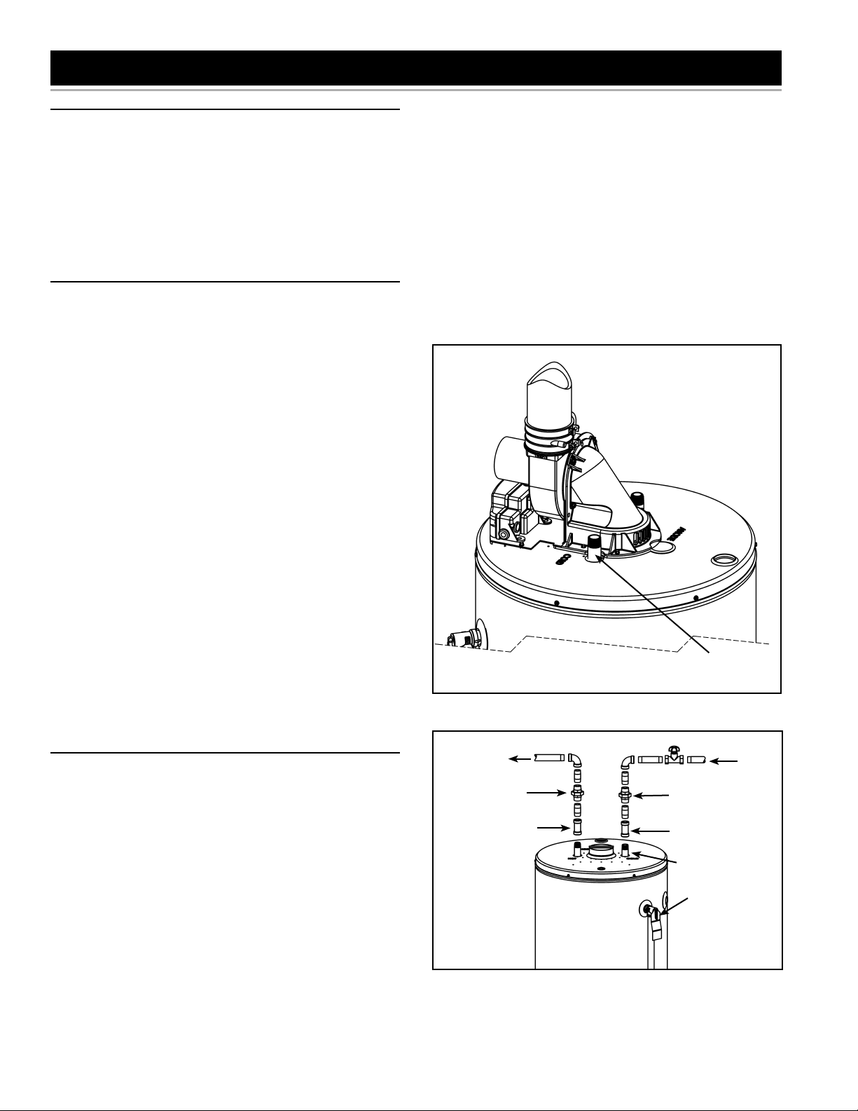
Remove the inlet water piping connected to the cold
inlet of the water heater (see Figures 5 & 6). Some
installations will have a union connection, others will
have the supply piping soldered to an adapter that
connects to the nipple on the water heater. Using the
pipe wrench remove the piping from the top of the
tank.
With the piping removed, use the pipe wrench on the
exposed nipple directly to remove it from the heater.
Note: Sometimes the dip tube will come out with the
piping in one piece. Separate accordingly.
6.
After turning off the hot-water faucet, check for water
leaks around dip tube and immediately correct any if
found.
7.
Reinstall the pipe insulation removed in step 4 removal
process.
8.
Reconnect the electrical power to the water heater in
the wall outlet and turn the gas supply back “ON” to
the gas control valve/thermostat.
9.
Turn the gas control switch to the “ON” position (see
Figure 3).
10.
To restart the water heater, follow the directions on
the “Lighting and Operating Instructions” label located
on the front of the water heater near the gas control
valve/thermostat.
NIPPLE/DIP
TUBE
Figure 5
Installing Dip Tube:
Use Tefl on® tape or an approved pipe sealant on
1.
threads of the new dip tube.
Place the dip tube into the spud on top of the tank
2.
HOT-WATER
OUTLET
UNION
SHUT-OFF VALVE
UNION
COLD-
WATER
INLET
and turn clockwise until tight. Using the pipe wrench
continue to tighten until the joint is water tight. Note:
Do not clamp the pipe wrench jaws on the threaded
portion of the nipple and do not over tighten. This can
cause the threads to distort and can result in a leak.
Apply Tefl on® tape or pipe sealant on the top threads
3.
and reconnect the water piping (see Figure 6).
Turn the main water supply back on.
4.
Open a nearby hot-water faucet to purge air from the
5.
water line. Fill water heater tank completely (Note: To
assure the water heater tank is full, keep the hot-water
3/4” SWEAT
FITTING
BLOWER
ASSEMBLY
COMPONENTS
NOT SHOWN
FOR CLARITY.
3/4” SWEAT
FITTING
NIPPLE/DIP
TUBE
TEMPERATUREPRESSURE
RELIEF VALVE
Figure 6
faucet open for 3 minutes after a constant fl ow of water
is obtained).
7
DOOR-BURNER ASSEMBLY REMOVAL/REPLACEMENT
INNER DOOR/MANIFOLD/BURNER ASSEMBLY
Important: Use only factory authorized replacement parts.
If you lack the necessary skills to properly perform the
installation, you should not proceed, but get help from a
qualifi ed service technician.
Tools required:
•
3/4” Open-End Wrench
•
Phillips Head Screwdriver
•
Ratchet with 1/4” socket or 1/4” nutdriver
•
Flashlight
Removing Inner Door/Manifold/Burner Assembly
1.
Set the gas control valve/thermostat to its lowest
setting by turning the knob counter-clockwise to the
VAC point (see Figure 3).
2.
Turn gas control switch to the “OFF” position and turn
“OFF” the gas supply to the unit (see Figure 3).
3.
Disconnect the electrical power to the water heater
from the wall outlet.
4.
Remove the outer door from the unit.
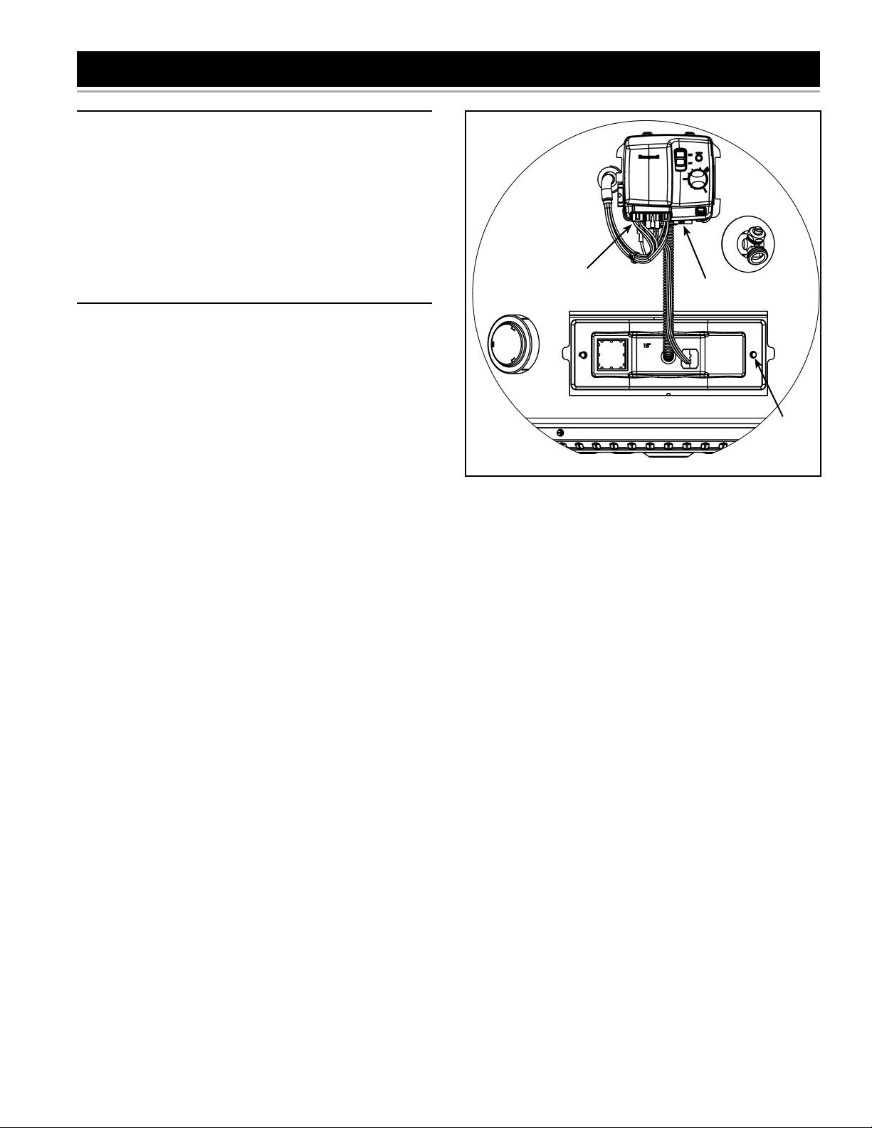
5.
Unplug all the electrical connections from the bottom
of the gas control valve/thermostat (see Figure 7).
6.
Using a 3/4” open end wrench remove the manifold
tube from the gas control valve/thermostat (turning
counter-clockwise for natural gas, clockwise for L.P.).
Grasp the manifold tube and push down slightly to
free the manifold tube from the gas control valve/
thermostat (see Figure 7).
7.
Remove the insulation pad on the inner door by cutting
it if necessary. Keep the insulation in a safe place for
reusing it later.
8.
Use a 1/4” nutdriver or 1/4” socket & ratchet to loosen
the 2 hex head screws on the inner door so the inner
door/manifold/burner assembly can be removed (see
Figure 7).
9.
Remove inner door/manifold/burner assembly by
grasping the manifold and pull back slowly. Rotating
it to the left to clear the igniter and fl ame sensor. Care
should be taken when inner door and burner assembly
passes through jacket opening that it does not damage
any of the electrical wiring (see Figure 9).
NOTE: OUTER DOOR AND INSULATION NOT SHOWN FOR CLARITY.
ELECTRICAL
CONNECTIONS
MANIFOLD
TUBE NUT
Figure 7
HEX HEAD
SCREWS
Caution Must Be Taken
Prior to installing the new inner door/manifold/burner, look
inside the burner chamber to fully understand the correct
positioning of the burner assembly and burner manifold
tab. It is necessary to use a fl ashlight to ensure correct
placement. Care must be taken so as to not damage any
electrical wiring or components as you are installing the
new inner door/manifold/burner assembly.
Extra caution should be taken to ensure that electrical
wiring, fi berglass insulation or any other object is not
between door gasket and combustion chamber shield.
Note: If the burner door gasket (see Figure 9) is worn
or damaged it needs to be replaced. See section “Door
Gasket Replacement”.
8
Re-installing Inner Door/Manifold/Burner Assembly
Insert the manifold/burner assembly in the
1.
burner chamber compartment, making sure
that the tip of burner manifold tab engages in
the proper slot of the bracket (see Figure 8).
Important:
• The tip end of the burner manifold MUST be placed
in the upper slotted portion for models with input rate
of 40,000 to 50,000 Btu/hr to obtain proper installation.
• The tip end of the burner manifold MUST be
placed in the lower slotted portion for models with
input rate of 60,000 to 75,000 Btu/hr to obtain proper
installation.
After confi rming no materials of any type are between
2.
door gasket and combustion chamber shield, align
the screws on the inner door with the screw holes
on the combustion chamber and tighten with 1/4”
nutdriver or 1/4” socket & ratchet (see Figure 7). After
tightening the inner door screws, visually inspect
area around door gasket and skirt for spaces or
gaps. The door gasket MUST be sealed completely
in order for the water heater to perform properly.
DO NOT OPERATE THE WATER HEATER IF THE
DOOR GASKET DOES NOT CREATE A SEAL
BETWEEN MANIFOLD DOOR AND COMBUSTION
CHAMBER.
Reconnect the manifold tube to the gas control valve/
3.
thermostat (Note: Do Not apply any thread sealant
at this connection). To prevent any cross threading
the manifold tube should be started by hand (turn
clockwise for natural gas, counter-clockwise for L.P.).
Upon tightening with the fi ngers and confi rming it has
not been cross threaded, tighten nut with a 3/4” open
end wrench (see Figure 7).
Reinstall the insulation pad which was removed in
4.
step 7 above.
Reconnect all the electrical connections to the bottom
5.
of the gas control valve/thermostat, gently pushing
each connector up until it snaps into place (see Figures
7 & 10).
Reconnect the electrical power to the water heater in
6.
the wall outlet and turn the main gas supply back “ON”
to the gas control valve/thermostat.
Restart the water heater by following the directions on
7.
the “Lighting and Operating Instructions” label located
on the front of the water heater. Test gas connections
by brushing on an approved non-corrosive leak
detection solution. (Note: Do not splash the solution
on control. If a leak is detected, shut the water heater
down by following the directions on the “Lighting and
Operating Instructions”. Repair the leak(s) and repeat
this step.
Upon verifying proper operation of the water heater,
8.
replace the insulation and outer door.
BURNER SUPPORT
BRACKET -
LOCATED IN THE
CENTRE OF THE
CHAMBER.
OUTER DOOR
ELECTRICAL
CONNECTIONS
STRAIGHT SLOT
FOR 40-50K
BURNERS WITH
STRAIGHT
MANIFOLD TUBES
Figure 8
INSULATION
PAD
Figure 9
CURVED SLOT FOR
60-75K BURNERS
MANIFOLD TUBES
GASKET ON
REAR OF DOOR
MOUNTING CLIP
(1 EACH SIDE)
WITH OFFSET
COMBUSTION
CHAMBER
OPENING
Figure 10
9

FLAME SENSOR AND IGNITER REMOVAL/REPLACEMENT
Remove and discard the old fl ame sensor and/or hot
FLAME SENSOR AND/OR HOT SURFACE IGNITER
Important: Use only factory authorized replacement parts.
If you lack the necessary skills to properly perform the
installation, you should not proceed, but get help from a
qualifi ed service technician.
Tools required:
•
3/4” Open-End Wrench
•
Phillips Head Screwdriver
•
Ratchet with 1/4” socket or 1/4” nutdriver
•
Flashlight
•
Flat Blade screwdriver
Removing Inner Door/Manifold/Burner Assembly:
1.
Set the gas control valve/thermostat to its lowest
setting by turning the knob counter-clockwise to the
VAC point (see Figure 3).
2.
Turn gas control switch to the “OFF” position and turn
“OFF” the gas supply to the unit (see Figure 3).
3.
Disconnect the electrical power to the water heater
from the wall outlet.
4.
Remove the outer door from the unit.
5.
Unplug all the electrical connections from the bottom
of the gas control valve/thermostat (see Figure 11).
6.
Using a 3/4” open end wrench remove the manifold
tube from the gas control valve/thermostat (turning
counter-clockwise for natural gas, clockwise for L.P.).
Grasp the manifold tube and push down slightly to
free the manifold tube from the gas control valve/
thermostat (see Figure 11).
7.
Remove the insulation pad on the inner door by cutting
it if necessary. Keep the insulation in a safe place for
reusing it later.
8.
Use a 1/4” nutdriver or 1/4” socket & ratchet to loosen
the 2 hex head screws on the inner door so the inner
door/manifold/burner assembly can be removed (see
Figure 11).
9.
Remove inner door/manifold/burner assembly by
grasping the manifold, rotating it to the left to clear the
igniter and fl ame sensor and pulling back. Care should
be taken when inner door and burner assembly passes
through jacket opening that it does not damage any
of the electrical wiring (see Figure 13).
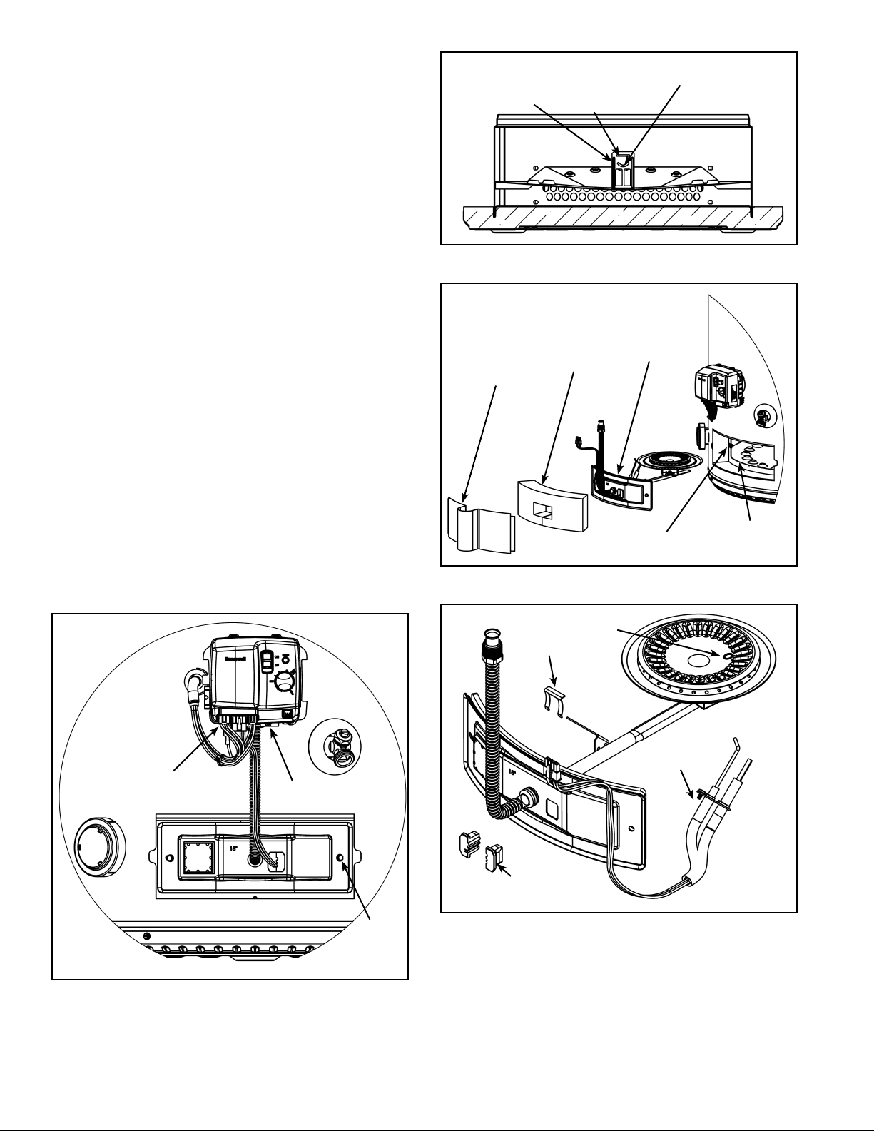
Removing Flame Sensor And/Or Hot Surface Igniter:
Note: The confi guration of the fl ame sensor and igniter
allows you to replace them separately. It is recommended
to clean the fl ame sensor when you replace the igniter.
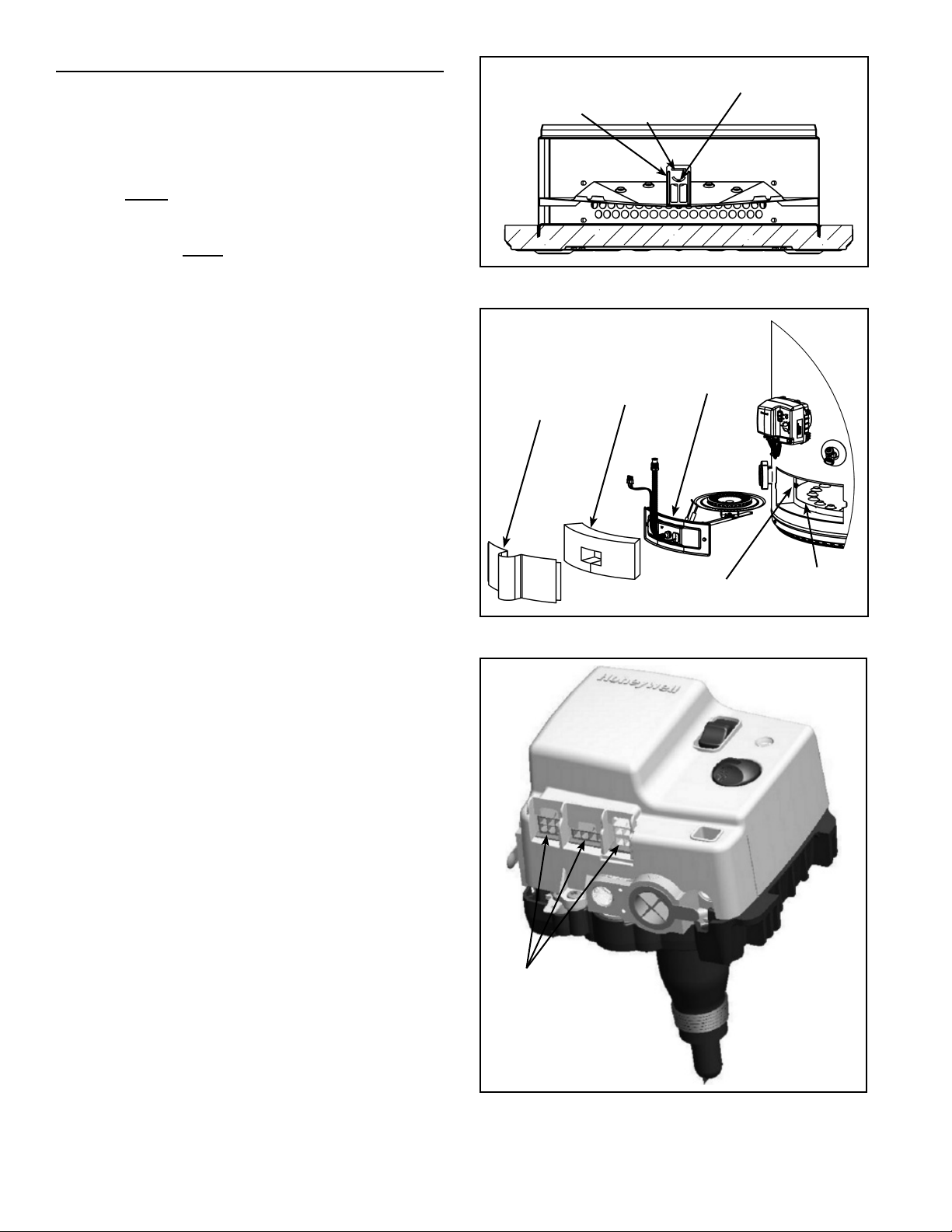
1.
Lift the retainer clip straight up from the back of
the manifold component block (using a fl at-blade
screwdriver), then remove the manifold component
block from the manifold door (see Figure 14).
2.
Disconnect the wiring connection between the fl ame
sensor/igniter and valve.
3.
Remove and retain the screw(s) securing the fl ame sensor
and/or hot surface igniter assembly (see Figure 14).
4.
surface igniter assembly.
Install the new Flame Sensor and/or Hot Surface
5.
Igniter.
Route the new fl ame sensor and/or hot surface igniter
6.
connector wire through manifold/burner door opening.
Secure the assembly to the bracket using screw(s)
removed in step 3 above.
Reconnect the wiring connection between the fl ame
7.
sensor/igniter and the valve.
Reposition the manifold component block in the
8.
manifold door opening and secure it with the retainer
clip.
Caution Must Be Taken
Prior to installing the new inner door/manifold/ burner
assembly, look inside the burner chamber to fully
understand the correct positioning of the burner assembly
and burner manifold tab. It may be necessary to use a
fl ashlight to ensure correct placement. Care must be taken
so as to not damage any electrical wiring or components
as you are installing the new inner door/manifold/burner
assembly.
Extra caution should be taken to ensure that electrical
wiring, fi berglass insulation or any other object is not
caught between door gasket and combustion chamber
shield.
Note: If the burner door gasket (see Figure 9) is worn
or damaged it needs to be replaced. See section “Door
Gasket Replacement”.
Re-installing Inner Door/Manifold/Burner Assembly
Insert the manifold/burner assembly in the burner
1.
chamber compartment, making sure that the tip of burner
manifold tab engages in the proper slot of the bracket
(see Figure 12). The tip end of the burner manifold MUST
be placed in the slotted portion under the condensation
pan to obtain proper installation (see Figure 12).
Important:
• The tip end of the burner manifold MUST be placed
in the upper slotted portion for models with input rate
of 40,000 to 50,000 Btu/hr to obtain proper installation.
• The tip end of the burner manifold MUST be
placed in the lower slotted portion for models with
input rate of 60,000 to 75,000 Btu/hr to obtain proper
installation.
After confi rming no materials of any type are between
2.
door gasket and combustion chamber shield, align
the screws on the inner door with the screw holes
on the combustion chamber and tighten with 1/4”
nutdriver or 1/4” socket & ratchet (see Figure 11).
After tightening the inner door screws, visually inspect
area around door gasket and skirt for spaces or
gaps. The door gasket MUST be sealed completely
in order for the water heater to perform properly.
DO NOT OPERATE THE WATER HEATER IF THE DOOR
GASKET DOES NOT CREATE A SEAL BETWEEN
MANIFOLD DOOR AND COMBUSTION CHAMBER.
10
Reconnect the manifold tube to the gas control valve/
thermostat (Note: Do Not apply any thread sealant
at this connection). To prevent any cross threading
the manifold tube should be started by hand (turn
clockwise for natural gas, counter-clockwise for L.P.).
Upon tightening with the fi ngers and confi rming it has
not been cross threaded, tighten nut with an 3/4” open
end wrench (see Figure 11).
3.
Reconnect all the electrical connections to the bottom
of the gas control valve/thermostat, gently pushing
each connector up until it snaps into place (see Figures
10 & 11).
4.
Reconnect the electrical power to the water heater in
the wall outlet and turn the main gas supply back “ON”
to the gas control valve/thermostat.
5.
Restart the water heater by following the directions on
the “Lighting and Operating Instructions” label located
on the front of the water heater.
6.
As the burner is heating (view flames through
viewport), test the manifold tube connection at
the gas control valve/thermostat by brushing on
an approved noncorrosive leak detection solution
(Important: Do Not splash the solution onto any
electrical connections. If a leak is detected, shut the
water heater down by following the directions on the
“Lighting and Operating Instructions”. Repair the
leak(s) and repeat step 6 above).
7.
Upon verifying proper operation of the water heater,
reinstall the insulation and the outer door.
Note: The structure of fl ame sensor/hot surface
igniter allows you to remove and replace them
separately.
BURNER SUPPORT
BRACKET -
LOCATED IN THE
CENTRE OF THE
CHAMBER.
OUTER DOOR
STRIGHT SLOT FOR
40-50K BURNERS
WITH STRAIGHT
MANIFOLD TUBES
Figure 12
INSULATION
PAD
GASKET ON
REAR OF DOOR
MOUNTING CLIP
(1 EACH SIDE)
Figure 13
CURVED SLOT FOR
60-75K BURNERS
WITH OFFSET
MANIFOLD TUBES
COMBUSTION
CHAMBER
OPENING
ELECTRICAL
CONNECTIONS
NOTE: OUTER DOOR AND INSULATION NOT SHOWN FOR CLARITY.
MANIFOLD
TUBE NUT
HEX HEAD
SCREWS
Figure 11
RETAINER
CLIP
COMPONENT
BLOCK
DRAIN
HOLE
IGNITER/
SENSOR
ASSEMBLY
Figure 14
11

BURNER AND ORIFICE REMOVAL/REPLACEMENT
BURNER
Important: Use only factory authorized replacement parts.
If you lack the necessary skills to properly perform the
installation, you should not proceed, but get help from a
qualifi ed service technician.
Tools required:
•
3/4” Open-End Wrench
•
Phillips Head Screwdriver
•
Ratchet with 1/4” socket or 1/4” nutdriver.
Removing Inner Door/Manifold/Burner Assembly:
1.
Set the gas control valve/thermostat to its lowest
setting by turning the knob counter-clockwise to the
VAC point (see Figure 3).
2.
Turn gas control switch to the “OFF” position and turn
“OFF” the gas supply to the unit (see Figure 3).
3.
Disconnect the electrical power to the water heater
from the wall outlet.
4.
Remove the outer door from the unit.
5.
Unplug all the electrical connections from the bottom
of the gas control valve/thermostat (see Figure 15).
6.
Using a 3/4” open end wrench remove the manifold
tube from the gas control valve/thermostat (turning
counter-clockwise for natural gas, clockwise for L.P.).
Grasp the manifold tube and push down slightly to
free the manifold tube from the gas control valve/
thermostat (see Figure 15).
7.
Remove the insulation pad on the inner door by cutting
it if necessary. Keep the insulation in a safe place for
reusing it later.
8.
Use a 1/4” nutdriver or 1/4” socket & ratchet to loosen
the 2 hex head screws on the inner door so the inner
door/manifold/burner assembly can be removed (see
Figure 15).
9.
Remove inner door/manifold/burner assembly by
grasping the manifold, rotating it to the left to clear the
igniter and fl ame sensor and pulling back. Care should
be taken when inner door and burner assembly passes
through jacket opening that it does not damage any
of the electrical wiring (see Figure 17).
Removing Burner:
1.
Burner may be hot. Wait until burner has cooled
off. After noting the position of the condensation
drain hole on the top of the burner, turn the inner
door/manifold/burner assembly upsidedown. Using
a Phillips head screwdriver, remove and retain the 2
screws attaching the burner to the manifold pipe (see
Figure 18 & 19).
Installing Burner:
Care MUST be taken to ensure the burner is installed
correctly on the inner door/manifold assembly. Position
the new burner upside down with the orientation of the
burner’s condensation drain as shown in illustration (see
Figure 18 & 19).
Align the screw holes on the inner door/manifold
1.
assembly. Using the two screws removed in step 1
of Removing Burner, install the new burner to the
inner door/ manifold assembly (rotate the assembly to
visually check the top portion of the burner assembly
and confi rm the orientation of the condensation drain
hole (see Figure 19 and note).
Caution Must Be Taken
Prior to installing the new inner door/manifold/burner
assembly, look inside the burner chamber to fully
understand the correct positioning of the burner assembly
and burner manifold tab. It may be necessary to use a
fl ashlight to ensure correct placement. Care must be taken
so as to not damage any electrical wiring, or components
as you are installing the new inner door/manifold/burner
assembly. Extra caution should be taken to ensure that
electrical wiring, fi berglass insulation or any other object
is not between door gasket and combustion chamber
shield. Note: If the burner door gasket (see Figure 9) is
worn or damaged it needs to be replaced. See section
“Door Gasket Replacement”.
Reinstalling Inner Door/Manifold/Burner Assembly
Insert the manifold/burner assembly in the burner
1.
chamber compartment, making sure that the tip of
burner manifold tab engages in the proper slot of the
bracket. The tip end of the burner manifold MUST be
placed in the slotted portion under the condensation
pan to obtain proper installation (see Figure 16).
Important:
• The tip end of the burner manifold MUST be placed
in the upper slotted portion for models with input rate
of 40,000 to 50,000 Btu/hr to obtain proper installation.
• The tip end of the burner manifold MUST be
placed in the lower slotted portion for models with
input rate of 60,000 to 75,000 Btu/hr to obtain proper
installation.
After confi rming no materials of any type are between
2.
door gasket and combustion chamber shield, align
the screws on the inner door with the screw holes
on the combustion chamber and tighten with 1/4”
nutdriver or 1/4” socket & ratchet (see Figure 15).
After tightening the inner door screws, visually inspect
area around door gasket and skirt for spaces or
gaps. The door gasket MUST be sealed completely
in order for the water heater to perform properly.
DO NOT OPERATE THE WATER HEATER IF THE
DOOR GASKET DOES NOT CREATE A SEAL
BETWEEN MANIFOLD DOOR AND COMBUSTION
CHAMBER.
Reconnect the manifold tube to the gas control valve/
3.
thermostat (Note: Do Not apply any thread sealant
at this connection). To prevent any cross threading
the manifold tube should be started by hand (turn
clockwise for natural gas, counter-clockwise for L.P.).
Upon tightening with the fi ngers and confi rming it has
not been cross threaded, tighten nut with a 3/4” open
end wrench (see Figure 15).
12
 Loading...