


Installation and Operating Manual
RESIDENTIAL GAS WATER HEATERS
POWER VENTED GAS MODELS
WITH HOT SURFACE IGNITION
NOT FOR USE IN MANUFACTURED (MOBILE) HOMES
• For Your Safety •
AN ODORANT IS ADDED TO THE GAS USED
BY THIS WATER HEATER.
ALL TECHNICAL AND WARRANTY QUESTIONS: SHOULD BE DIRECTED TO THE LOCAL DEALER FROM WHOM THE WATER HEATER WAS PURCHASED. IF YOU ARE UNSUCCESSFUL, PLEASE CONTACT THE COMPANY LISTED ON THE RATING PLATE ON THE WATER HEATER.
|
KEEP THIS MANUAL IN THE POCKET ON HEATER FOR FUTURE REFERENCE |
|
WHENEVER MAINTENANCE ADJUSTMENT OR SERVICE IS REQUIRED. |
1306 |
322151-003 |

TABLE OF CONTENTS
TABLE OF CONTENTS |
2 |
High Ambient Temperature Installations . . . . . . . . . |
28 |
|
SAFE INSTALLATION, USE AND SERVICE |
3 |
Polypropylene Vent Systems . . . . . . . . . . . . . . . . . |
29 |
|
GENERAL SAFETY |
4 |
Condensate. . . . . . . . . . . . . . . . . . . . . . . . . . . . . . . |
29 |
|
INTRODUCTION |
6 |
Exhaust Venting . . . . . . . . . . . . . . . . . . . . . . . . . . . |
30 |
|
Qualified Installer Or Service Agency . . . . . . . . . . . |
. 6 |
Important Notes and Warnings |
|
|
Preparing For The Installation. . . . . . . . . . . . . . . . . |
. 6 |
Venting terminations and sizing |
|
|
INSTALLATION REQUIREMENTS FOR THE |
|
Vent screen installation |
|
|
COMMONWEALTH OF MASSACHUSETTS |
7 |
Calculating Equivalent Feet |
|
|
TYPICAL INSTALLATION |
9 |
Venting instructions |
|
|
Get To Know Your Water Heater - Gas Models (List |
|
Vent pipe connection to blower |
|
|
Referencing Figures 1-7) . . . . . . . . . . . . . . . . . . . . |
. 9 |
Different coupling installations according to vent sizes |
||
Replacement Parts And Deliming Products . . . . . . |
10 |
Blower Exhaust Direction . . . . . . . . . . . . . . . . . . . . |
35 |
|
Combo Heating Inlet And Outlet Side Taps. . . . . . . |
10 |
Vent Pipe Preparation . . . . . . . . . . . . . . . . . . . . . . . |
35 |
|
Water Piping - Mixing Valve Usage . . . . . . . . . . . . . . |
11 |
Installation Checklist . . . . . . . . . . . . . . . . . . . . . . . . |
38 |
|
Mixing Valves |
|
LIGHTING INSTRUCTIONS |
39 |
|
Water Heater Operation . . . . . . . . . . . . . . . . . . . . . |
12 |
OPERATING THE TEMPERATURE |
|
|
Electrical Requirements & Wiring Diagram . . . . . . . |
13 |
CONTROL SYSTEM |
40 |
|
SAFETY LOCKOUTS |
14 |
Gas Control Valve/Thermostat . . . . . . . . . . . . . . . . |
41 |
|
High Limit Controls (Energy Cut Off). . . . . . . . . . . . |
14 |
FOR YOUR INFORMATION |
42 |
|
Thermostat/Water Temperature |
|
Start Up Conditions . . . . . . . . . . . . . . . . . . . . . . . . . |
42 |
|
Blower High Limit Switch |
|
Condensate |
|
|
Blower Air Pressure Switch . . . . . . . . . . . . . . . . . . . |
14 |
Thermal expansion |
|
|
Flammable Vapor Sensor . . . . . . . . . . . . . . . . . . . . |
14 |
Closed water systems |
|
|
LOCATING THE NEW WATER HEATER |
15 |
Smoke/odor |
|
|
Strange sounds |
|
|||
Facts To Consider About The Location |
15 |
|
||
Operational Conditions |
42 |
|||
Storage Of Flammable Liquids |
15 |
|||
Smelly water |
|
|||
Clearances to combustibles |
|
|
||
|
“Air” In Hot-Water Faucets |
43 |
||
Floors with carpeting |
|
|||
|
PERIODIC MAINTENANCE |
44 |
||
Clearance for servicing |
|
|||
|
General Upkeep |
44 |
||
Insulation Blankets |
17 |
|||
Venting System Inspection |
44 |
|||
Air Requirements |
17 |
|||
Blower Maintenance |
44 |
|||
Unconfined Space |
17 |
|||
Cleaning The Blower |
44 |
|||
Unusually Tight Construction |
17 |
|||
Burner Operation And Inspection |
45 |
|||
Confined Space |
17 |
|||
Combustion Chamber And Burner Cleaning |
46 |
|||
Direct Vent Appliances |
18 |
|||
Housekeeping |
46 |
|||
Exhaust Fans |
18 |
|||
Anode Rod Inspection |
46 |
|||
Fresh Air Openings For Confined Spaces |
18 |
|||
Anode Rod |
46 |
|||
Chemical Vapor Corrosion |
19 |
|||
Removing Anode Rod: |
|
|||
INSTALLING THE NEW WATER HEATER |
20 |
|
||
Installing Anode Rod: |
|
|||
Water Piping |
20 |
|
||
Temperature-Pressure Relief Valve Test |
47 |
|||
Space Heating And Potable Water Systems |
20 |
|||
Draining And Flushing |
48 |
|||
Combo Heating |
21 |
|||
To drain the water heater storage tank: |
|
|||
System Requirements |
|
|
||
|
To flush the water heater storage tank: |
|
||
Installation |
|
|
||
|
LEAKAGE CHECKPOINTS |
49 |
||
Closed Water Systems |
22 |
|||
Service |
49 |
|||
Thermal Expansion |
22 |
|||
REFERENCE PARTS LISTING |
50 |
|||
Temperature-Pressure Relief Valve |
23 |
|||
TROUBLESHOOTING GUIDELINES |
52 |
|||
T&P valve discharge pipe requirements: |
|
Resetting The Heater Control |
54 |
|
Temperature-Pressure Relief Valve and |
|
|||
|
Lockouts |
54 |
||
Pipe Insulation |
|
|||
|
Soft Lockout |
|
||
High Altitude Installation |
24 |
|
||
Hard Lockout |
|
|||
Gas Piping |
24 |
|
||
Ignition State And Timing |
55 |
|||
Sediment Traps/Dirt Leg |
25 |
|||
System Status And Error Codes |
55 |
|||
Filling The Water Heater |
26 |
|||
LIMITED WARRANTY |
58 |
|||
Venting |
26 |
|||
|
|
|||
Termination Clearances Sidewall Power Vent. . . . . |
27 |
|
|
|
Blower Assembly Installation. . . . . . . . . . . . . . . . . . |
28 |
|
|
|
Installation Of Vent System . . . . . . . . . . . . . . . . . . . |
28 |
|
|
|
Planning The Vent System . . . . . . . . . . . . . . . . . . . |
28 |
|
|
|
2 |
www.hotwater.com |
SAFE INSTALLATION, USE AND SERVICE
Your safety and the safety of others is extremely important in the installation, use and servicing of this water heater. Many safety-related messages and instructions have been provided in this manual and on your own water heater to warn you and others of a potential injury hazard. Read and obey all safety messages and instructions throughout this manual. It is very important that the meaning of each safety message is understood by you and others who install, use or service this water heater.
This is the safety alert symbol. It is used to alert you to potential personal injury hazards. Obey all safety messages that follow this symbol to avoid possible injury or death.
DANGER indicates an imminently DANGER hazardous situation which, if not avoided,
will result in death or injury.
WARNING indicates a potentially WARNING hazardous situation which, if not avoided,
could result in death or injury.
CAUTIONindicatesapotentiallyhazardous CAUTION situation which, if not avoided, could
result in minor or moderate injury.
CAUTION used without the safety alert CAUTION symbol indicates a potentially hazardous situation which, if not avoided, could
result in property damage
All safety messages will generally tell you about the type of hazard, what can happen if you do not follow the safety message and how to avoid the risk of injury.
The California Safe Drinking Water and Toxic Enforcement Act requires the Governor of California to publish a list of substances known to the State of California to cause cancer, birth defects or other reproductive harm and requires businesses to warn of potential exposure to such substances.
This product contains a chemical known to the State of California to cause cancer, birth defects or other reproductive harm. This appliance can cause low level exposure to some of the substances listed in the Act.
IMPORTANT DEFINITIONS
Qualified Installer: A qualified installer must have ability equivalent to a licensed tradesman in the fields of plumbing, air supply, venting and gas supply, including a thorough understanding of the requirements of the National Fuel Gas Code as it relates to the installation of gas fired water heaters. The qualified installer must also be familiar with the design features and use of flammable vapor ignition resistant water heaters and have a thorough understanding of this Installation and Operating manual.
Service Agency: A service agency also must have ability equivalent to a licensed tradesman in the fields of plumbing, air supply, venting and gas supply, including a thorough understanding of the requirements of the National Fuel Gas Code as it relates to the installation of gas fired water heaters. The service agency must also have a thorough understanding of this Installation and Operating manual, and be able to perform repairs strictly in accordance with the service guidelines provided by the manufacturer.
Gas Supplier: The Natural Gas or Propane Utility or service who supplies gas for utilization by the gas burning appliances within this application. The gas supplier typically has responsibility for the inspection and code approval of gas piping up to and including the Natural Gas meter or Propane storage tank of a building. Many gas suppliers also offer service and inspection of appliances within the building.
www.hotwater.com |
3 |

GENERAL SAFETY
4 |
www.hotwater.com |
GENERAL SAFETY
|
|
|
|
|
DANGER |
WARNING |
|
|
|
|
|
Breathing Hazard - Carbon Monoxide Gas
• Install vent system in accordance with codes.
• Do not operate water heater if flood damaged.
• For operation above 10,100’, a high altitude |
|
|
orifice must be installed. |
|
|
• Do not operate if soot buildup is present. |
|
|
• Do not obstruct water heater air intake with |
FLAMMBLE |
Flammable Vapors |
insulating jacket. |
• Do not obstruct blower air intake. |
|
Vapors from flammable |
Water heater has a main |
||
• Do not place chemical vapor emitting products |
|
||||
near water heater. |
liquids may explode and |
burner and hot surface igniter. |
|||
• Gas and carbon monoxide detectors are |
catch fire causing death or |
The hot surface igniter: |
|||
available. |
severe burns. |
1. |
can be triggered at any |
||
• No vent damper installation is compatible with |
Do not use or store |
2. |
time and |
||
this power vented water heater. |
the hot surface will ignite |
||||
|
|
flammable products such as |
|
flammable vapors. |
|
Breathing carbon monoxide can cause brain damage or death. |
|
||||
gasoline, solvents or adhe- |
Vapors: |
||||
Always read and understand instruction manual. |
sives in the same room or |
||||
|
|
area near the water heater. |
1. |
cannot be seen, |
|
|
|
Keep flammable products: |
2. |
are heavier than air, |
|
|
|
3. |
go a long way on the floor |
||
|
|
1. |
far away from heater, |
4. |
and |
|
|
2. |
in approved containers, |
can be carried from other |
|
|
|
3. |
tightly closed and |
|
rooms to the the |
|
|
4. |
out of children's reach. |
|
electodes by air currents. |
|
|
|
|||
|
|
Installation: Do not install the water heater where flammable |
|||
|
|
products will be stored or used. |
|
|
|
www.hotwater.com |
5 |

INTRODUCTION
Thank You for purchasing this water heater. Properly installed and maintained, it should give you years of trouble free service.
Abbreviations found in this Installation and Operating manual:
•CSA - Canadian Standards Association
•ANSI - American National Standards Institute
•NFPA - National Fire Protection Association
•ASME - American Society of Mechanical Engineers
•UL - Underwriters Laboratories Inc.
•AHRI - Air Conditioning, Heating and Refrigeration Institute.
This gas-fired water heater is design certified by CSA International, under Water Heater Standard ANSI Z21.10.1 • CSA 4.1 (current edition).
QUALIFIED INSTALLER OR SERVICE AGENCY
Installation and service of this water heater requires ability equivalent to that of a Qualified Agency (as defined by ANSI below) in the field involved. Installation skills such as plumbing, air supply, venting, gas supply and electrical supply are required in addition to electrical testing skills when performing service.
ANSI Z223.1 2006 Sec. 3.3.83: “Qualified Agency” - “Any individual, firm, corporation or company that either in person or through a representative is engaged in and is responsible for (a) the installation, testing or replacement of gas piping or (b) the connection, installation, testing, repair or servicing of appliances and equipment; that is experienced in such work; that is familiar with all precautions required and that has complied with all the requirements of the authority having jurisdiction.”
If you are not qualified (as defined by ANSI above) and licensed or certified as required by authority having jurisdiction to perform a given task, do not attempt to perform any of the procedures described in this manual. If you do not understand the instructions given in this manual do not attempt to perform any procedures outlined in this manual.
PREPARING FOR THE INSTALLATION
1.Read the “General Safety Information” section of this manual first and then entire manual carefully. If you don’t follow safety rules, the water heater will not operate properly. It could cause DEATH, SERIOUS BODILY INJURY AND/OR PROPERTY DAMAGE. This manual contains instructions for installation, operation, and maintenance of the gas-fired water heater. It also contains warnings throughout the manual that you must read and be aware of. All warnings and instructions are essential to proper operation of the water heater and your safety. Since we cannot put everything on the first few pages,
READ ENTIRE MANUAL BEFORE ATTEMPTING TO INSTALL OR OPERATE THE WATER HEATER.
2.The installation must conform with these instructions and local code authority having jurisdiction. In absence of local codes, installation must comply with current editions of the National Fuel Gas Code, ANSI Z223.1/ NFPA 54 and National Electrical Code, NFPA 70. All documents are available from:
CSA International,
8501 East Pleasant Valley Road, Cleveland, Ohio, United States 44131-5575.
NFPA documents are also available from: National Fire Protection Association,
1 Batterymarch Park, Quincy, MA 02269.
3.The water heater, when installed, must be electrically grounded in accordance with the local codes or in the absence of local codes: the National Electrical Code (NFPA 70).
4.If after reading this manual you have any questions or do not understand any portion of the instructions, call the local gas utility or the manufacturer whose name appears on the rating plate.
5.Carefully plan the place where you are going to put the water heater. Correct combustion, vent action, and vent pipe installation are very important in preventing death from possible carbon monoxide poisoning and fires (see Figure 14 & Figure 15). Examine the location to ensure the water heater complies with the “Locating the New Water Heater” section in this manual.
6.For installation in California, this water heater must be braced, anchored, or strapped to avoid falling or moving during an earthquake. See instructions for correct installation procedures. Instructions may be obtained from:
California Office of the State Architect, 400 P Street,
Sacramento, CA 95814.
7.Massachusetts Code requires this water heater to be installed In accordance with Massachusetts 248-CMR 2.00: State Plumbing Code and 248-CMR 5.00.
8.Complies with California Health and Safety code 116875 (known as AB-1953) and with weighted average maximum of 0.25% lead.
6 |
www.hotwater.com |

INSTALLATION REQUIREMENTS FOR THE COMMONWEALTH OF MASSACHUSETTS
COMMONWEALTH OF MASSACHUSETTS
For all side wall terminated, horizontally vented power vent, direct vent and power direct vent gas fueled water heaters installed in every dwelling, building or structure used in whole or in part for residential purposes, including those owned or operated by the Commonwealth and where the side wall exhaust vent termination is less than seven (7) feet above finished grade in the area of the venting, including but not limited to decks and porches, the following requirements shall be satisfied:
INSTALLATION OF CARBON MONOXIDE DETECTORS
At the time of installation of the side wall horizontal vented gas fueled equipment, the installing plumber or gasfitter shall observe that a hard wired carbon monoxide detector with an alarm and battery back-up is installed on the floor level where the gas equipment is to be installed. In addition, the installing plumber or gasfitter shall observe that a battery operated or hard wired carbon monoxide detector with an alarm is installed on each additional level of the dwelling, building or structure served by the sidewall horizontal vented gas fueled equipment. It shall be the responsibility of the property owner to secure the services of qualified licensed professionals for the installation of hard wired carbon monoxide detectors. In the event that the side wall horizontally vented gas fueled equipment is installed in a crawl space or an attic, the hard wired carbon monoxide detector with alarm and battery back-up may be installed on the next adjacent floor level.
In the event that the requirements of this subdivision can not be met at the time of completion of installation, the owner shall have a period of thirty (30) days to comply with the above requirements provided that during said thirty (30) day period, a battery operated carbon monoxide detector with an alarm shall be installed.
APPROVED CARBON MONOXIDE DETECTORS
Each carbon monoxide detector as required in accordance with the above provisions shall comply with NFPA 720 and be ANSI/ UL 2034 listed and CSA certified.
SIGNAGE
A metal or plastic identification plate shall be permanently mounted to the exterior of the building at a minimum height of eight (8) feet above grade directly in line with the exhaust vent terminal for the horizontally vented gas fueled heating appliance or equipment. The sign shall read, in print size no less than onehalf (1/2) inch in size, “GAS VENT DIRECTLY BELOW. KEEP CLEAR OF ALL OBSTRUCTIONS.”
INSPECTION
The state or local gas inspector of the side wall horizontally vented gas fueled equipment shall not approve the installation unless, upon inspection, the inspector observes carbon monoxide detectors and signage installed in accordance with the provisions of 248 CMR 5.08(2)(a) 1 through 4.
EXEMPTIONS
The following equipment is exempt from 248 CMR 5.08(2) (a) 1 through 4:
1.The equipment listed in Chapter 10 entitled “Equipment Not Required To Be Vented” in the most current edition of NFPA 54 as adopted by the Board; and
2.Product Approved side wall horizontally vented gas fueled equipment installed in a room or structure separate from the dwelling, building, or structure used in whole or in part for residential purposes.
MANUFACTURER REQUIREMENTS - GAS EQUIPMENT VENTING SYSTEM PROVIDED
When the manufacturer of Product Approved side wall horizontally vented gas equipment provides a venting system design or venting system components with the equipment, the instructions provided by the manufacturer for installation of the equipment and the venting system shall include:
1.Detailed instructions for the installation of the venting system design or the venting system components; and
2.A complete parts list for the venting system design or venting system.
MANUFACTURER REQUIREMENTS - GAS EQUIPMENT VENTING SYSTEM NOT PROVIDED
When the manufacturer of Product Approved side wall horizontally vented gas fueled equipment does not provide the parts for venting the flue gases, but identifies “special venting systems,” the following requirements shall be satisfied by the manufacturer:
1.The referenced “special venting system” instructions shall be included with the appliance or equipment installation instructions; and
2.The “special venting systems” shall be Product Approved by the Board, and the instructions for that system shall include a parts list and detailed installation instructions.
A copy of all installation instructions for all Product Approved side wall horizontally vented gas fueled equipment, all venting instructions, all parts lists for venting instructions, and/or all venting design instructions shall remain with the appliance or equipment at the completion of the installation.
www.hotwater.com |
7 |
INSTALLATION GRAPHIC: GAS-FIRED POTABLE WATER HEATING/SPACE HEATING SYSTEM
•If your water heater will be installed in the Commonwealth of Massachusetts, refer to the following graphic during installation and during modifications to the water supply system.
TYPICAL MIXING VALVE INSTALLATION
COMBINATION SPACE HEATING / POTABLE WATER HEATING SYSTEM
|
|
|
|
|
EXPANSION TANK |
|
|
COLD WATER INLET |
|||||
|
|
|
|
|
|
|
|
|
|
CHECK VALVE † |
SHUT-OFF |
||
TEMPERED WATER |
CHECK |
VACUUM |
|
|
|
|
|
(1/8” HOLE |
VALVE |
||||
|
|
|
|
DRILLED IN CLAPPER) |
|
||||||||
TO FIXTURES |
VALVE † |
RELIEF |
|
|
|
|
|
||||||
|
|
|
|
|
|
|
|
|
|||||
(MUST MEET TEMPS LISTED |
|
|
|
VALVE |
|
|
|
|
|
|
|
|
|
|
|
|
|
|
|
|
|
|
|
|
|
||
|
|
|
|
|
|
|
|
|
|
|
|
|
|
IN MASS. CODE 248 CMR † ) |
|
|
|
|
|
|
|
|
|
|
|
|
|
|
|
|
|
|
|
|
|
|
|
|
|
|
|
|
|
|
|
|
|
|
|
|
|
|
|
|
|
UNION
MUST BE VERTICAL TO
REMOVE AIR BUBBLES
|
|
HOT |
||
|
|
|||
|
|
WATER |
||
MIXING VALVE |
|
OUT |
||
|
|
|
|
|
(MUST BE INSTALLED BELOW TOP OF WATER HEATER
AS PER MANUFACTURER’S RECOMMENDATIONS)
WATER HEATER ACCEPTED
BY THE BOARD FOR
INSTALLATION IN
MASSACHUSETTS. †
*MASSACHUSETTS INSTALLATION REQUIREMENTS:
FLOW CONTROL
VALVE
UNION |
PUMP * |
|
TEMP/ |
OUT |
|
PRESSURE |
IN |
|
RELIEF |
|
|
VALVE |
|
|
TO |
COIL |
|
AIR |
|
|
HANDLER |
|
|
SEE |
|
|
NOTE ‡ |
AIR |
|
SHUT-OFF |
HANDLER |
|
|
|
|
VALVE * |
|
|
100’-0” MAXIMUM DISTANCE |
|
|
FROM WATER HEATER TO FAN |
|
|
COIL AND BACK. (DEVELOPED |
|
|
LENGTH) NOT INCLUDING COIL |
|
|
IN HEATING UNIT † |
|
|
1.) CONNECT ELECTRONICALLY-CONTROLLED TIMER TO AN ALL-BRONZE PUMP. PUMP MUST ACTIVATE EVERY 6 HOURS FOR 60 SECONDS. TURN PUMP TIMER OFF BEFORE CLOSING PIPING LOOP SHUT-OFF VALVE.
2.) ALL WATER PIPING MUST BE INSTALLED AND INSULATED IN ACCORDANCE WITH MASSACHUSETTS CODE (248 CMR & 780 CMR).
3.) PIPING LOOP BETWEEN WATER HEATER AND AIR HANDLER MUST BE INSTALLED IN COMPLIANCE WITH 248 CMR.
†REQUIRED FOR MASSACHUSETTS.
‡PIPING FROM THE TOP OF THE WATER HEATER WITH TEES IS ACCEPTABLE.
|
|
|
8 |
www.hotwater.com |
|
TYPICAL INSTALLATION
GET TO KNOW YOUR WATER HEATER - GAS MODELS (list referencing Figures 1-7)
1.Vent Termination Elbow with Rodent Screen
2.*Vent Pipe
3.*Vent Pipe Coupling (if required)
4.*Vent Pipe Elbow (long radius)
5.Blower High Limit Switch (see Figure 6)
6.T&P Valve
7.Cold-Water Inlet Nipple/Diptube
8.Baffle Assembly
9.* Discharge Pipe
10.Gas Control Valve/Thermostat (Honeywell)
11.Gas Valve Electronic Control Module And Cover (Honeywell)
12.Drain Valve
13.Outer Gas Door
14.Manifold Door Assembly (behind outer door) (see Figure 3 & Figure 4)
15.*Floor Drain
16.*Metal Drain Pan
17.Flammable Vapor Sensor (under cover) (see Figure 5)
1 |
2 |
3 |
4 |
26
21
21
48 

8
43
44
45
46
32 
17
16 |
Front View |
|
Figure 1. |
18.**Combo Heating System Return Inlet (Optional)
19.Air Inlet Snorkel
20.**Combo Heating System Supply Outlet (Optional)
21.Blower with Power Cord (see also Figure 6)
22.Air Switch (inside box) (see Figure 6)
23.Junction Box (see Figure 6)
24.Junction Box Cover (see Figure 6)
25.Air Tubing (see Figure 6)
26.Rubber Coupling (see also Figure 6)
27.Gear Clamp (see also Figure 6)
28.Flue Collector
29.Hot-Water Outlet Nipple
30.Anode (under cap)
31.***Control Harness
32.Flexible Manifold Tube (see Figure 3 & Figure 4)
33.Viewport (see Figure 3 & Figure 4)
34.Flame Sensor Rod (see Figure 3 & Figure 4)
27
42
35.Gas Orifice (see Figure 3 & Figure 4)
36.Sheet Metal Burner (see Figure 3 & Figure 4)
37.Gas Manifold (see Figure 3 & Figure 4)
38.Hot-Surface Igniter (see Figure 3 & Figure 4)
39.Manifold Door Gasket (see Figure 3 & Figure 4)
40.Manifold Door (see Figure 3 & Figure 4)
41.Two Piece Grommet With Clip (see Figure 3 & Figure 4)
42.*Inlet Water Shut-off Valve
43.*Gas Supply*
44.*Main Manual Gas Shut-off Valve
45.*Ground Joint Union (gas connection)
46.*Sediment Trap/Dirt Leg
47.*Union (water connection)
48.Rating Plate
49.*Thermal Expansion Tank (required for all closed systems)
*, **, ***, **** see notes on following page
 27
27
6 |
49 |
47 |
47 |
|
|||
|
|
|
|
20 |
|
28 |
29 |
|
|
||
|
|
30 |
|
7 |
|
7 |
|
|
|
Blower
9 Dilution Air
Inlets
10 11
Combustion
Air Inlets
18
19
31
12
13 14
15
Figure 2.
www.hotwater.com |
9 |

Natural gas and Propane main burner with igniter assembly for 40k to 50k Btu/hr models
34
32 |
35 |
33
41
Figure 3.
Natural gas and Propane main burner with igniter assembly for 60k to 75k Btu/hr models
32 |
34 35 |
33
41
Figure 4.
17
Figure 5.
36
37
38
39
40
36
37
38
39
40
22 |
25 |
26 |
23
27
24
5
21
Figure 6.
Vacuum relief valve install per local codes (not supplied with heater).
Figure 7.
Notes:
*Items not supplied with the water heater.
**The side recirculation loop connections may not be used as the primary water inlet and outlet connections. See “Combo Heating Inlet And Outlet Side Taps” below.
***Caution harness has 120 VAC In operation.
****See “Planning The Vent System”, “Condensate” and “Blower Assembly Installation” for more information.
REPLACEMENT PARTS AND DELIMING PRODUCTS
Replacement parts and recommended delimer may be ordered through authorized servicers or distributors. When ordering parts, provide complete model and serial numbers (see rating plate), quantity and name of part desired. Standard hardware items may be purchased locally.
COMBO HEATING INLET AND OUTLET SIDE TAPS
Models equipped with Combo Heating capabilities are shipped with the two side plumbing taps OPEN (items 18 and 20 in Figure 1 and see also Figure 8 & Figure 25). If the heater is to be operated without using the side taps, these openings must be closed with the two pipe plugs supplied with the heaters.
10 |
www.hotwater.com |
WATER PIPING - MIXING VALVE USAGE
Mixing Valves
DANGER Water temperature over 125°F can cause severe
burns instantly resulting in severe injury or death.
|
|
|
|
Children, the elderly and the |
|
|
|
|
disabled and are at highest |
|
|
|
|
risk of scald injury. |
|
|
|
|
Feel water before bathing or |
|
|
|
|
showering. |
|
|
|
|
Temperature limiting devices |
HOT |
such as mixing must be |
|||
installed when required by |
||||
|
|
|
|
codes and to ensure safe |
|
|
|
|
|
|
BURN |
temperatures at fixtures. |
||
|
|
|||
Water heated to a temperature which satisfies space heating, clothes washing, dish washing, and other sanitizing needs can scald and cause permanent injury upon contact. Short repeated heating cycles caused by small hot-water uses can cause a temperature increase of the hot water by 20F° higher than the heater’s temperature settings.
SUGGESTED PIPING |
TEMPERED |
SHUT-OFF |
ARRANGEMENT FOR |
POTABLE WATER |
VALVE |
TOP CONNECTIONS |
|
COLD-WATER |
MIXING VALVE |
|
|
|
INLET |
|
TEMPERATURE- |
|
CERTAIN |
PRESSURE |
|
MODELS ARE |
RELIEF VALVE |
|
EQUIPPED WITH |
* NOTE: THE |
|
SIDE PLUMBING |
|
CONNECTIONS |
|
T&P VALVE |
|
|
|
FOR SPACE |
|
DISCHARGE |
|
|
|
HEATING. THE HOT |
|
PIPE MUST |
|
|
|
AND COLD FITTING |
|
BE PIPED |
|
|
|
ASSEMBLIES |
|
DIRECTLY TO |
|
|
|
(PART #9001262) |
|
THE DRAIN |
|
|
|
CAN BE ORDERED |
|
OR EXTERNAL |
|
|
|
THROUGH THE |
|
TO THE |
|
|
|
MANUFACTURER |
|
BUILDING |
|
|
|
|
DISCHARGE
PIPE (DO NOT
CAP OR PLUG) METAL DRAIN PAN 1.75”
MAX. DEPTH.
AT LEAST 2”
GREATER THAN
THE DIAMETER
OF THE WATER
HEATER.
GAS
SUPPLY
6” MAX.
AIR GAP* DRAIN VALVE
MASSACHUSETTS: INSTALL A VACUUM RELIEF IN COLD WATER LINE PER SECTION 19 MGL 142.
Figure 8.
his appliance has been design certified as complying with American National Standard/CSA Standard for water heaters and certain models with side plumbing connections are considered suitable for Water (Potable) Heating and Space Heating. Note: Do not use in space heating only applications.
The water supply pressure should not exceed 80 psi. If this occurs, a pressure reducing valve with a bypass should be installed in the cold water inlet line. This should be placed on the supply to the entire house in order to maintain equal hot and cold water pressures.
SUGGESTED PIPING |
TEMPERED |
ARRANGEMENT FOR |
POTABLE WATER |
TOP CONNECTIONS |
|
NON-TEMPERED |
|
WATER SUPPLY |
|
MIXING VALVE |
|
MASSACHUSETTS: INSTALL A VACUUM RELIEF IN COLD WATER LINE PER SECTION 19 MGL 142.
GAS
SUPPLY 
DRAIN
VALVE
METAL DRAIN PAN 1.75” MAX.
DEPTH. AT
LEAST
2” GREATER
THAN THE
DIAMETER OF THE WATER HEATER.
SHUT-OFF  VALVE
VALVE
COLD-WATER  INLET
INLET
NON-TEMPERED WATER RETURN
TEMPERATUREPRESSURE  RELIEF VALVE
DISCHARGE
PIPE (DO NOT
CAP OR PLUG)
* NOTE: THE
T&P VALVE
DISCHARGE PIPE MUST BE PIPED DIRECTLY TO THE DRAIN OR EXTERNAL TO THE BUILDING
6” MAX. AIR GAP*
Figure 9.
www.hotwater.com |
11 |
Some people are more likely to be permanently injured by hot water than others. These include the elderly, children, the infirm and the physically/mentally disabled. Table 1 (published by U.S. Government Memorandum, 1978) shows the approximate time-to-burn relationship for normal adult skin. If anyone using hot water provided by the water heater being installed fits into one of these groups or if there is a local code or state law requiring a certain water temperature at the point of use, then special precautions must be taken.
Water |
Time for 1st |
Time for Permanent |
|
Burns 2nd & 3rd |
|||
Temperature |
Degree Burns |
||
Degree (Most |
|||
°F |
(Less Severe Burns) |
||
Severe Burns) |
|||
|
|
||
110 |
(normal shower temp.) |
|
|
|
|
|
|
116 |
(pain threshold) |
|
|
116 |
35 minutes |
45 minutes |
|
|
|
|
|
122 |
1 minute |
5 minutes |
|
131 |
5 seconds |
25 seconds |
|
140 |
2 seconds |
5 seconds |
|
149 |
1 second |
2 seconds |
|
154 |
instantaneous |
1 seconds |
(U.S. Government Memorandum, C.P.S.C., Peter L. Armstrong,
Sept. 15,1978)
Table 1.
In addition to using lowest possible temperature setting that satisfies demand of application, a mixing valve should be installed at water heater (see Figure 8 & Figure 9) or at hot-water taps to further reduce system water temperature. Mixing valves are available at plumbing supply stores. Consult a Qualified Installer or Service Agency. Follow mixing valve manufacturer’s instructions for installation of the valves. Before changing the factory setting on the thermostat, read the “Operating The Temperature Control System” section in this manual.
WATER HEATER OPERATION
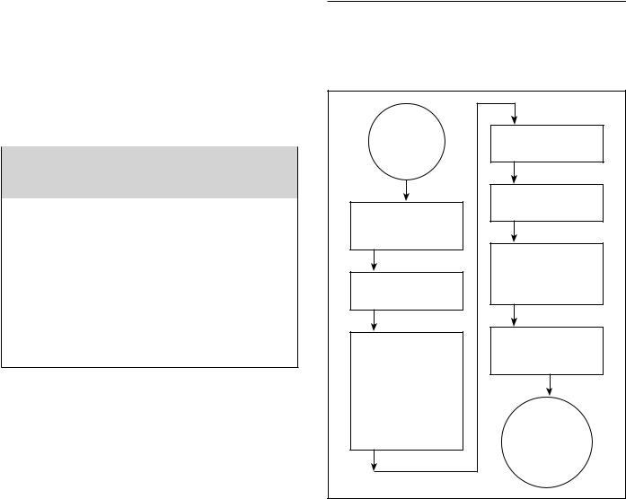
Figure 10 shows the water heater’s sequence of operation when a call for heat is initiated. The ignition control module will attempt to light the burner three times. If the ignition control does not detect ignition it will enter lockout mode and flash the corresponding error code.
HEATER
THERMOSTAT
CALLS FOR
HEAT
HEATER CONTROL CHECKS TO ENSURE BLOWER PRESSURE SWITCH IS OPEN
BLOWER IS
ENERGIZED
CONTROL CHECKS TO ENSURE PRESSURE SWITCH CLOSES INDICATING BLOWER IS OPERATING AND THERE ARE NO VENTING BLOCKAGES (INLET OR OUTLET)
IGNITER IS ENERGIZED AND MAIN GAS VALVE IS OPENED
MAIN BURNER COMES ON AND THE FLAME IS SENSED BY CONTROL
MAIN BURNER CONTINUES TILL THE WATER IN THE TANK REACHES THERMOSTAT SETTING
MAIN BURNER SHUTS
OFF. BLOWER
CONTINUES FOR A POST PURGE TIME
HEATER
REMAINS ON
STANDBY UNTIL
NEXT CALL FOR
HEAT
Figure 10.
12 |
www.hotwater.com |
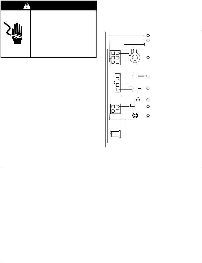
ELECTRICAL REQUIREMENTS & WIRING DIAGRAM
Before plugging in the water heater, always make sure:
•The voltage and frequency correspond to that specified on the water heater wiring diagram.
•The electrical outlet has the proper overload fuse or breaker protection.
1.The unit must be connected to a dedicated power supply.
2.The unit must be connected to a 120VAC power supply.
3.The water heater must be properly grounded.
4.This water heater is a polarity sensitive appliance and will not operate if the power supply polarity is reversed.
Note: Always reference the wiring diagram for the correct electrical connections.
After making all electrical connections, completely fill the tank with water and check all connections for leaks. Open the nearest hot-water faucet and let it run for 3 minutes to purge the water lines of air and sediment and to ensure complete filling of the tank. The electrical power may then be turned on. Verify proper operation after servicing. See also “Installation Checklist”.
CAUTION
LABELALL WIRES PRIOR TO DISCONNECTION WHEN SERVICING CONTROLS. WIRING ERRORS CAN CAUSE IMPROPER AND DANGEROUS OPERATION. VERIFY PROPER OPERATION AFTER SERVICING.
POWER VENT WIRING SCHEMATIC.
NOTE: REFER TO THE “INSTALLATION CHECKLIST” BEFORE OPERATING THIS HEATER.
|
|
|
1 |
N |
|
|
|
1 |
L1 |
|
|
|
|
EARTH GND |
|
|
|
|
CAPACITOR |
6 |
3 |
|
|
|
5 |
2 |
P1 |
4 |
BLOWER |
4 |
1 |
|
|
|
|
4 |
|
7 |
FLAME SENSOR |
|
3 |
P2 |
|
|
|
2 |
|
|
|
|
|
|
|
|
|
1 |
|
6 |
HOT SURFACE IGNITER |
|
|
|
|
|
|
5 |
PRESSURE SWITCH |
4 |
2 |
3 |
HIGH LIMIT SWITCH |
3 |
1 |
P3 |
|
|
|
||
|
|
2 |
FLAMMABLE VAPOUR SENSOR |
P4 |
Circled numbers indicate |
|
sequence of operation. |
Figure 11.
Figure 12.
www.hotwater.com |
13 |
SAFETY LOCKOUTS
This water heater has several lockout features designed to prevent the heater from operating in unsafe conditions.
HIGH LIMIT CONTROLS (Energy Cut Off)
Thermostat/Water Temperature
This feature is a part of the gas control valve/thermostat (see Figure 1, item 10) and limits the maximum water temperature. In the event of the water overheating, this safety feature shuts off the fuel supply to the burner.
Blower High Limit Switch
This device is located on the blower (see Figure 6, item 5) and limits the maximum temperature of the blower. If the blower temperature rises above the temperature setting, the switch opens causing the heater to shut down. The switch will auto reset once the temperature drops sufficiently.
BLOWER AIR PRESSURE SWITCH
This device, located in the junction box, monitors the air pressure produced by the blower. In the event that the exhaust venting becomes blocked or sufficiently restricted, the switch will shut the heater down (see Figure 6, item 22).
FLAMMABLE VAPOR SENSOR
When using a gas fired water heater there is a risk of flammable vapors entering the combustion chamber, being ignited by the burner flame and causing a flashback. In order to detect such flammable vapors before they enter the combustion chamber, this water heater is equipped with a flammable vapor sensor (FVS). It is a chemicalabsorption based sensor that is connected to the gas control/thermostat (see Figure 13). When exposed to flammable vapors it will trigger the control to stop the flow of gas and enter the FVS lockout state. While in the FVS lockout state the LED on the control will flash the gas lockout code. (Refer to the “System Status And Error Codes” section of this manual for an explanation of the codes applicable to the control installed on your water heater.) If this error occurs, check around the water heater for sources of chemical contamination such as: flammable vapors including gas vapors, solvents, paint and thinners as well as sources of water and detergents.
Note: Resetting the heater will reset the FVIR circuit if all sources of contamination have been removed and the sensor clears. If all sources of contamination have been removed and the system will not reset, the sensor will need to be replaced (see “Resetting the Heater Control”).
If there is a problem with the wiring of the flammable vapor sensor or the flammable vapor interface, the LED will flash the failure status code (see “System Status And Error Codes”).
* ROTATE LEFT (CCW) TO REMOVE
COVER*
MOUNTING
BRACKET
FLAMMABLE
VAPOR SENSOR (PULL TO REMOVE)
Figure 13.
14 |
www.hotwater.com |

LOCATING THE NEW WATER HEATER
FACTS TO CONSIDER ABOUT THE LOCATION
Carefully choose an indoor location for the new water heater because the placement is a very important consideration for the safety of the occupants in the building and for the most economical use of the appliance. This water heater is not for use in manufactured (mobile) homes or outdoor installation.
Whether replacing an old water heater or putting the water heater in a new location, the following critical points must be observed:
1.Select a location indoors as close as practical to the vent termination or location to which the water heater vent piping is going to be connected, and as centralized with the water piping system as possible.
2.Selected location must provide adequate clearances for servicing and proper operation of the water heater.
3.Ensure the area has a continuous supply of air for combustion, dilution and ventilation.
4.Avoid locations that could cause the water heater to freeze from outside air.
5.Selected location must provide access to a properly grounded electrical branch circuit. A dedicated circuit is preferred. Do not use a GFI outlet.
6.Avoid locations that expose the water heater to direct sunlight.
7.Keep combustibles such as boxes, magazines, clothes, etc., away from the water heater area.
Important: Do not use an extension cord to connect the water heater to an electrical outlet.
Important: this heater has special venting requirements when installed in areas where the ambient temperatures exceed 110°F (see “High Ambient Temperature Installations”).
CAUTION
Property Damage Hazard
•All water heaters eventually leak.
•Do not install without adequate drainage.
Installation of the water heater must be accomplished in such a manner that if the tank or any connections should leak, the flow of water will not cause damage to the structure. For this reason it is not advisable to install the water heater in an attic or upper floor. In all cases, a metal drain pan should be installed under the water heater. Metal drain pans are available at your local hardware store. Such a metal drain pan must have a clearance of at least 1” greater than any point on the water heater’s outer jacket and must be piped to an adequate drain. The pan must have a maximum depth of 1.75”.
Water heater life depends upon water quality, water pressure and the environment in which the water heater is installed. Water heaters are sometimes installed in locations where leakage may result in property damage, even with the use of a metal drain pan piped to a drain. However, unanticipated damage can be reduced or
prevented by a leak detector or water shut-off device used in conjunction with a piped metal drain pan. These devices are available from some plumbing supply wholesalers and retailers, and detect and react to leakage in various ways:
•Sensors mounted in the metal drain pan that trigger an alarm or turn off the incoming water to the water heater when leakage is detected.
•Sensors mounted in the metal drain pan that turn off the water supply to the entire building when water is detected in the metal drain pan.
•Water supply shut-off devices that activate based on the water pressure differential between the cold-water and hot-water pipes connected to the water heater.
•Devices that will turn off the gas supply to a gas water heater while at the same time shutting off its water supply.
STORAGE OF FLAMMABLE LIQUIDS
Flammable liquids (such as gasoline, solvents, propane (LP or butane, etc.) and other substances (such as adhesives, paints, etc.) emit flammable vapors which can be ignited by a gas water heater’s hot surface igniter (HSI) or main burner. The resulting flashback and fire can cause death or serious burns to anyone in the area.
This water heater is equipped with a FV (Flammable Vapor) sensor for detecting the presence of flammable vapors. When the sensor detects those vapors, the unit will shut down and not operate. Should this happen, please refer to the “Troubleshooting Guidelines” section of this manual. Even though this water heater is a flammable vapors ignition resistant (FVIR) water heater and is designed to reduce the chances of flammable vapors being ignited, gasoline and other flammable substances should never be stored or used in the same vicinity or area containing a gas water heater or other open flame or spark producing appliance. Examples of such locations are garages, storage and utility areas.
The water heater must be located and/or protected so it is not subject to physical damage by a moving vehicle.
www.hotwater.com |
15 |
 WARNING
Fire or Explosion Hazard
•Do not store or use gasoline or other flammable vapors and liquids in the vicinity of this or any other appliance.
•Avoid all ignition sources if you smell gas.
•Do not expose water heater control to excessive gas pressure.
•Use only gas shown on rating plate.
•Maintain required clearances to combustibles.
•Keep ignition sources away from faucets after extended period of non-use.
Read instruction manual before installing, using or servicing water heater.
 WARNING
Fire Hazard
For continued protection against risk of fire:
•Do not install water heater on carpeted floor.
•Do not operate water heater if flood damaged.
Clearances to combustibles
Minimum clearances between water heater and combustibles are 0” at the sides and rear, 5.5” from the front and 12” from top (standard clearance.) If clearances stated on the heater differ from standard clearances, install water heater according to clearances stated on the heater (see Figure 14).
Floors with carpeting
This water heater must not be installed directly on carpeting. Carpeting must be protected by a metal or wood panel beneath the appliance extending beyond the full width and depth of the appliance by at least 3” in every direction, or if the appliance is installed in an alcove or closet, the entire floor must be covered by the panel. Failure to heed this warning may result in a fire hazard.
Clearance for servicing
Adequate clearance of 24” for servicing this appliance should be considered before installation, such as changing the anodes, etc.
A minimum clearance of 5.5” must be allowed for access to replaceable parts such as thermostats, drain valve and relief valve.
When installing the heater, consideration must be given to proper location. Location selected should be as close to the wall as practicable and as centralized with the water piping system as possible.
TOP VIEW |
TOP VIEW OF |
OF CLOSET |
CLOSET WITH |
WITHOUT DOOR AIR INTAKE* |
DOOR |
0” MIN. |
0” MIN. |
5.5” MIN.
0” MIN.

* DO NOT BLOCK THE AIR INTAKES AT THE BACK OF THE WATER HEATER.
Figure 14.
A gas water heater cannot operate properly without the correct amount of air for combustion and ventilation. Do not install in a confined area such as a closet unless you provide air as shown below and described in the “Air Requirements” section (see Figure 15). Never obstruct the flow of ventilation air for dilution and combustion. If you have any doubts or questions at all, call your gas supplier. Failure to provide the proper amount of combustion air can result in a fire or explosion and cause death, serious bodily injury, or property damage.
 WARNING
Breathing Hazard - Carbon Monoxide Gas
•Install water heater in accordance with the instruction manual and NFPA54.
•To avoid injury, combustion and ventilation air must be taken from outdoors.
•Do not place chemical vapor emitting products near water heater.
Breathing carbon monoxide can cause brain damage or death. Always read and understand instruction manual.
Figure 15.
16 |
www.hotwater.com |

If this water heater will be used in beauty shops, barber shops, cleaning establishments, or self-service laundries with dry cleaning equipment, it is imperative that the water heater or water heaters be installed so that combustion and ventilation air be taken from outside these areas.
Propellants of aerosol sprays and volatile compounds, (cleaners, chlorine based chemicals, refrigerants, etc.) in addition to being highly flammable in many cases, will also react to form corrosive hydrochloric acid when exposed to the combustion products of the water heater. The results can be hazardous, and also cause product failure.
INSULATION BLANKETS
Insulation blankets are available to the general public for external use on gas water heaters but are not necessary with these products. The purpose of an insulation blanket is to reduce standby heat loss encountered with storage tank heaters. Your water heater meets or exceeds the current standards with respect to insulation and standby loss requirements, making an insulation blanket unnecessary. Should you choose to apply an insulation blanket to this heater, you should follow these instructions (For identification of components mentioned below, see Figure 1 thru Figure 7). Failure to follow these instructions will restrict the air flow required for proper combustion and dilution, potentially resulting in fire, asphyxiation, serious personal injury or death.
•Do not apply insulation to the top of the water heater, as this will interfere with safe operation of the blower assembly.
•Do not cover the outer door, thermostat or T&P relief valve, FV sensor, or Air Intake Snorkel.
•Do not cover the “Installation And Operating manual”. Keep it on the side of the water heater or nearby for future reference.
•Do obtain new warning and instruction labels from the manufacturer for placement on the blanket directly over the existing labels.
•Do inspect the insulation blanket frequently to make certain it does not sag, thereby obstructing combustion air flow.
 WARNING
Breathing Hazard - Carbon Monoxide Gas
•Do not obstruct water heater air intake(s) with insulating jacket.
•Gas and carbcn monoxide detectors are available.
•Install water heater in accordance with the instruction manual and NFPA54.
Breathing carbon monoxide can cause brain damage or death. Always read and understand instruction manual.
AIR REQUIREMENTS
For safe operation an adequate supply of fresh, uncontaminated air for combustion, dilution and ventilation must be provided.
Note: Contaminated or dusty air may cause build-up on the blower wheel resulting in nuisance shut downs.
An insufficient supply of air can cause recirculation of combustion products resulting in contamination that may be hazardous to life. Such a condition often will result in a yellow, luminous burner flame, causing sooting of the combustion chamber, burners and flue tubes and creates a risk of asphyxiation.
Do not install the water heater in a confined space unless an adequate supply of air for combustion, dilution and ventilation is brought into that space using the methods described in the “Confined Space” section that follows.
Never obstruct the flow of dilution/ventilation air. If you have any doubts or questions at all, call your gas supplier. Failure to provide the proper amounts of air can result in a fire or explosion and cause property damage, serious bodily injury or death. The combustion and dilution air inlets are shown in Figure 2.
Important: Power Vented water heaters require air for combustion and dilution air for the blower.
UNCONFINED SPACE
An Unconfined Space is one whose volume is not less than 50 cubic feet per 1,000 Btu/hr of the total input rating of all appliances installed in the space. Rooms communicating directly with the space in which the appliances are installed, through openings not furnished with doors, are considered a part of the unconfined space.
Makeup air requirements for the operation of exhaust fans, kitchen ventilation systems, clothes dryers and fireplaces should also be considered in determining the adequacy of a space to provide combustion, ventilation and dilution air.
UNUSUALLY TIGHT CONSTRUCTION
In unconfined spaces in buildings, infiltration may be adequate to provide air for combustion, ventilation and dilution of flue gases. However, in buildings of unusually tight construction (e.g., weather stripping, heavily insulated, caulked, vapor barrier, etc.) additional air must be provided using the methods described in the “Confined Space” section that follows.
CONFINED SPACE
A Confined Space is one whose volume is less than 50 cubic feet per 1,000 Btu/hr of the total input rating of all appliances installed in the space.
Openings must be installed to provide fresh air for combustion, ventilation and dilution in confined spaces. The required size for the openings is dependent on the method used to provide fresh air to the confined space
www.hotwater.com |
17 |

and the total Btu/hr input rating of all appliances installed in the space.
DIRECT VENT APPLIANCES
Other appliances installed in a Direct Vent configuration that derive all air for combustion from the outdoor atmosphere through sealed intake air piping are not factored in the total appliance input Btu/hr calculations used to determine the size of openings providing fresh air into confined spaces.
EXHAUST FANS
Where exhaust fans are installed, additional air should be provided to replace the exhausted air. When an exhaust fan is installed in the same space with a water heater, sufficient openings to provide fresh air must be provided that accommodate the requirements for all appliances in the room and the exhaust fan. Undersized openings will cause air to be drawn into the room through the water heater’s vent system causing poor combustion. Sooting, serious damage to the water heater and the risk of fire or explosion may result. It can also create a risk of asphyxiation.
FRESH AIR OPENINGS FOR CONFINED SPACES
The following instructions should be used to calculate the size, number and placement of openings providing fresh air for combustion, ventilation and dilution in confined spaces. The illustrations shown in this section of the manual are a reference for the openings that provide fresh air into confined spaces only. Do not refer to these illustrations for the purpose of vent installation. See “Installation of Vent System” section for complete venting installation instructions.
Chemical vapor corrosion of the flue, blower assembly and vent system may occur if the air supply contains certain chemical vapors. Spray can propellants, cleaning solvents, refrigerator and air conditioner refrigerants, swimming pool chemicals, calcium and sodium chloride (water softener salt), waxes, bleach and process chemicals are typical compounds which are potentially corrosive.
A.ALL AIR FROM INSIDE BUILDINGS: (See Figure 16) The confined space shall be provided with two permanent openings communicating directly with an additional room(s) of sufficient volume so that the combined volume of all spaces meets the criteria for an unconfined space. The total input of all gas utilization equipment installed in the combined space shall be considered in making this determination. Each opening shall have a minimum free area of one square inch per 1,000 Btu/hr of the total input rating of all gas utilization equipment in the confined space, but not less than 100 square inches. One opening shall commence within 12” of the top and one commencing within 12” of the bottom of the enclosures.
Figure 16.
B.ALL AIR FROM OUTDOORS: (See Figure 17 thru Figure 19)
The confined space shall be provided with two permanent openings, one commencing within 12” of the top and one commencing within 12“ from the bottom of the enclosure. The openings shall communicate directly, or by ducts, with the outdoors or spaces (crawl or attic) that freely communicate with the outdoors.
1.When directly communicating with the outdoors, each opening shall have a minimum free area of 1 square inch per 4,000 Btu/hr of total input rating of all equipment in the enclosure (see Figure 17).
Figure 17.
2.When communicating with the outdoors through vertical ducts, each opening shall have a minimum free area of 1 square inch per 4,000 Btu/hr of total input rating of all equipment in the enclosure (see Figure 18).
3.When communicating with the outdoors through horizontal ducts, each opening shall have a minimum free area of 1 square inch per 2,000 Btu/hr of total input rating of all equipment in the enclosure (see Figure 19).
18 |
www.hotwater.com |
 Loading...