


A. O. SMITH WATER PRODUCTS COMPANY
VF BOILER SERVICE MANUAL
Technical Literature Department ©2008
CONTENTS
Introduction |
2 |
|
Troubleshooting - Error Messages |
41 |
|
||||
Qualifications.................................................................... |
2 |
|
Display Is Blank................................................................ |
42 |
Service Warning................................................................ |
2 |
|
Error Message “Display Fail”.......................................... |
43 |
Tools Required.................................................................. |
3 |
|
Error Message “No Config Key”...................................... |
43 |
EMC 5000 Modulation Control System........................... |
4 |
|
Error Message “Config Key CRC”................................... |
44 |
UIM - User Interface Module - Overview.......................... |
4 |
|
Error Message “Config Key Part”.................................... |
44 |
UIM - Status Lights........................................................... |
6 |
|
Error Message “Low AC Voltage”................................... |
45 |
UIM - Input Buttons........................................................... |
7 |
|
Error Message “Low 24 VAC”.......................................... |
45 |
UIM - Changing Settings.................................................. |
8 |
|
Error Message “Low Water”............................................ |
45 |
UIM - Menu Screens.......................................................... |
9 |
|
Error Message “Low Gas”............................................... |
45 |
Principles of Operation.................................................... |
11 |
|
Error Message “No Flow”................................................ |
46 |
VFD and Blower Operation.............................................. |
11 |
|
Error Message “Sequence Err”....................................... |
48 |
Venturi Operation - Gas Train.......................................... |
12 |
|
Error Message “Ignition Speed”...................................... |
48 |
Blower Speed Verification - Hall Effect Sensor.............. |
13 |
|
Error Message “Mtr Spd < Min Spd”............................... |
48 |
Config Key - Blower Speed Programming...................... |
14 |
|
Error Message “Blower Prov Stg1”................................. |
49 |
Sequence Of Operation.................................................... |
15 |
|
Error Message “Blocked Flue”........................................ |
56 |
START UP PROCEDURE.................................................. |
17 |
|
Error Message “Flame Stg1............................................. |
57 |
Adjusting Manifold Gas.................................................... |
19 |
|
Error Message “Igniter Stg1............................................ |
60 |
Poor Combustion - Ignition Problems............................ |
20 |
|
Boiler Controls Information............................................. |
61 |
Manifold Gas Pressure Check......................................... |
23 |
|
Operating Temperatures.................................................. |
67 |
Control Panel Layout........................................................ |
24 |
|
Bypass Lines..................................................................... |
67 |
MCB - Modulation Control Board.................................... |
25 |
|
Technical Specifications.................................................. |
68 |
PDB - Power Distribution Board...................................... |
35 |
|
Glossary............................................................................ |
71 |
|
|
|
|
|

VF BOILER SERVICE MANUAL
INTRODUCTION
This Service Manual is designed to aid in servicing and troubleshooting A. O. Smith VF boilers. Models VW/VB 500 - 1000 - series 100/101 boilers are covered in this manual.
The instructions and illustrations contained in this service manual will provide you with troubleshooting procedures to verify proper operation and diagnose and repair common service problems.
Important Service Reminder
When performing any troubleshooting step outlined in this service manual always consider the wiring and connectors between components. Perform a close visual inspection of all wiring and connectors to and from a given component before replacement. Ensure wires were stripped before being crimped in a wire connector, ensure wires are crimped tightly in their connectors, ensure connection pins in sockets and plugs are not damaged or worn, ensure plugs and sockets are mating properly and providing good contact.
Failure to perform this critical step or failing to perform this step thoroughly often results in needless down time, unnecessary parts replacement, and customer dissatisfaction.
Instruction Manual
Have a copy of the Instruction Manual that came with the boiler on hand for the model and series number before servicing.
Installation information given in this service manual is not a complete installation instruction. Installation information covered in this service manual has a limited focus as it applies to servicing the boiler. This Service Manual does not replace or supersede the Instruction
Manual that came with the boiler. Always refer to the Instruction Manual that came with the boiler for complete installation instructions.
Qualifications
Service of A. O. Smith VF boilers requires ability equivalent to that of a Qualified Service Agent (defined by ANSI below) in the field involved. Installation skills such as plumbing, air supply, venting, gas supply, electrical supply are required in addition to electrical testing skills. Start up and servicing of VF boilers requires combustion analysis test equipment.
ANSI Z223.1 2006 Sec. 3.3.83: “Qualified Agency” - “Any individual, firm, corporation or company that either in person or through a representative is engaged in and is responsible for (a) the installation, testing or replacement of gas piping or (b) the connection, installation, testing, repair or servicing of appliances and equipment; that is experienced in such work; that is familiar with all precautions required; and that has complied with all the requirements of the authority having jurisdiction.”
Service Warning
If you are not licensed or certified to perform a given task do not attempt to perform any of the service or installation procedures outlined in this manual. If you do not understand the instructions given in this manual or do not feel confident in your abilities to perform a given task do not attempt to perform any procedures outlined in this manual.
AOS WPC - Technical Literature Dept |
2 of 72 |
Ashland City, TN © 2008 |
Servicing should only be performed by a Qualified Service Agent |
|
|

VF BOILER SERVICE MANUAL
Tools Required
•Instruction Manual that came with the boiler.
•Hand tools common to installation and service of commercial water heaters and boilers.
•TORX® T40 or 5mm hex wrench - for setting gas mixture at gas valve.
•3mm or 7/64in hex (allen) wrench - for setting gas mixture at gas valve.
•One - U tube manometer for measuring supply gas pressure.
•One (optionally two) digital Manometers range -15.00 to +15.00" W.C., resolution 0.01"
W.C. Recommend UEI model EM200, TPI model 620 or equivalent. Used to measure manifold gas pressures and to test performance of air pressure switches. Optional second digital manometer can be used in place of U tube manometer for measuring supply gas pressure.
•True RMS Digital Multi Meter DMM, recommend UEI model DL289 or Fluke equivalent. Capable of measuring:
AC/DC Voltage
VAC Frequency (Hz)
Ohms
DC micro amps µA
•AC amp meterrecommend UEI model DL289 or equivalent.
•Combustion analyzer Capable of measuring:
CO2
CO
Draft Pressure
Exhaust Temperature
Efficiency
AOS WPC - Technical Literature Dept |
3 of 72 |
Ashland City, TN © 2008 |
Servicing should only be performed by a Qualified Service Agent |
|
|

VF BOILER SERVICE MANUAL
EMC 5000 MODULATION CONTROL SYSTEM
This portion of the service manual will cover the EMC 5000 Modulation Control system
(EMC - Energy Management Control). The EMC 5000 control system includes several components: a UIM (User Interface Module), a MCB (Modulation Control Board), and a PDB
(Power Distribution Board). The EMC 5000 Control System can control single stage, multiple stage, and modulating boilers and water heaters. This service manual should be used as a reference for A. O. Smith VW/VB 500-1000 Series 100-101 boilers only.
Features Include:
•EMI / RFI filtering - built into all circuit boards. (EMI = Electro Magnetic Interference, RFI = Radio Frequency Interference) Helps prevent or eliminate erratic operation caused by
EMI/RFI.
•Help screens - text based operational information to help the user understand how to change settings and navigate the menu screens.
•Self diagnostics - text based diagnostic information (error and fault messages) on board to help service technicians quickly and accurately service the boiler.
•Error message log - will retain a 9 event history (plus the current event) of error messages with a time stamp. This will help diagnose load and/or environmental conditions that may be contributing to a problem with operation or a lock-out.
•Short cycling protection - if any stage logs more than 30 cycles in one hour the control enters a short cycle prevention condition. The boiler will continue to operate in this mode.
The UIM will display and log a “Short Cycle Cond” error message with the yellow Standby system status LED flashing. The MCB will add a 180 second delay before activating any stage’s call for heat after the last call for heat during this operating mode.
The short cycle protection mode can be ended (reset) by touching the Select button on the
UIM while the error message is displayed.
•Temperature probe filtering - The inlet, outlet, and remote Tank/Loop temperature probes are read twice per second by the MCB and are filtered for 4 seconds. This filtering will help prevent rapid short cycling caused by momentary fluctuations in temperature.
•Pressure/flow switch filtering - input switches such as air pressure switches are read every second by the MCB and are filtered (de-bounced) for 6 seconds. This desensitizes the input signal and will help prevent nuisance error/fault conditions due to momentary fluctuations caused by wind gusts or blower speed changes. The flow switch is filtered for
4 seconds.
•Network capability - multiple boilers can be networked together (daisy chained) with standard Category 5/6 network cable and given individual network addresses.
•Access/monitoring with future A. O. Smith EMS (Energy Management System) controller.
AOS WPC - Technical Literature Dept |
4 of 72 |
Ashland City, TN © 2008 |
Servicing should only be performed by a Qualified Service Agent |
|
|
VF BOILER SERVICE MANUAL
UIM - USER INTERFACE MODULE - OVERVIEW
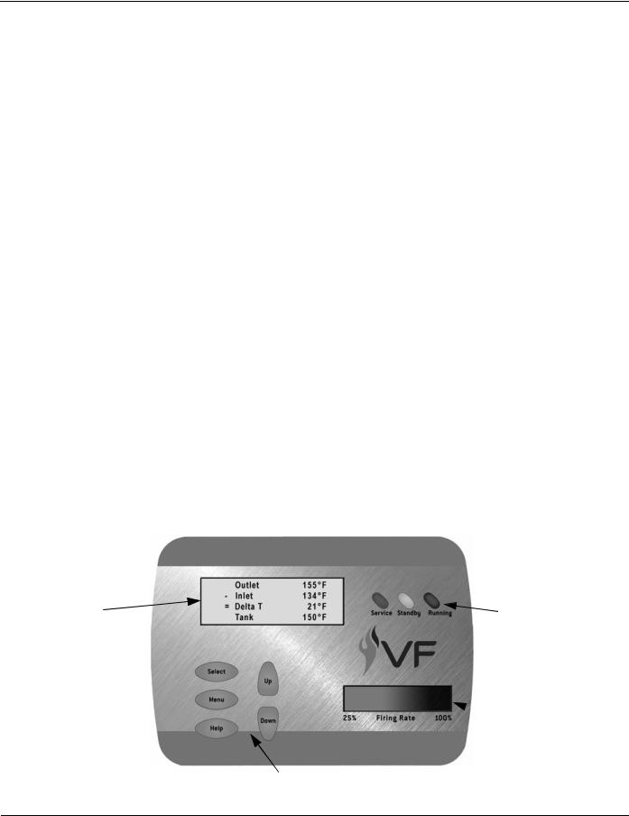
The UIM is an assembly that consists of several electronic components. The main circuit board in the assembly is the UIB (User Interface Board) which houses the communications port. The UIB relays user input and data to and from the MCB, controls the LCD, and activates the LEDs. Mounted to the UIB is a TSB (Touch Sensor Board) containing the touch sensor pads that are the user input buttons. There is a LCD module mounted to the UIB that displays operational information and diagnostic messages in plain English.
LEDs |
• Three “System Status” LED lights: Service, Standby, Running. |
(Light Emitting Diode) |
Located to the right of the LCD. |
|
• Firing Rate Status indicator - located in the lower right portion of |
|
the UIM. Four LED lights behind a green (gradient) translucent |
|
cover. This display indicates the approximate firing rate |
|
between 25% and 100%. |
|
|
LCD |
• LCD display - 4 lines, up to 20 characters per line. |
(Liquid Crystal Display) |
• 10 different screens - Menus, Temperatures, System Status, |
|
Control States, User Settings, Configuration Settings, Log & |
|
System Information, Current Error, Error History, and Reload |
|
Defaults (see page 9). |
|
• Text based operational and diagnostic information. |
|
|
User Input Buttons |
• Select - Menu - Help - Up - Down. |
|
• 5 touch sensitive buttons for user input. Located on the lower |
|
left portion of the UIM. |
|
• No moving parts - no pressure is required; these buttons |
|
activate on finger presence. |
|
|
Settings / Memory |
• Non volatile memory; once new settings are confirmed |
|
(touching the Select button) they remain in memory. |
|
|
LCD display |
System Status |
4 line x 20 character |
LEDs |
 Firing Rate Status
5 Touch Sensitive
User Input Buttons
AOS WPC - Technical Literature Dept |
5 of 72 |
Ashland City, TN © 2008 |
Servicing should only be performed by a Qualified Service Agent |
|
|

VF BOILER SERVICE MANUAL
UIM - USER INTERFACE MODULE - STATUS LIGHTS
 System Status
LEDs
LCD display
 4 line x 20 character
 Firing Rate
Status
5 Touch Sensitive
User Input Buttons
System Status LED Lights
The three “System Status” LED lights on the upper right portion of the UIM convey current operational and diagnostic information.
The red Service LED will be continuously illuminated for soft lock-outs and flashing on and off for hard lockouts.
Soft lock-outs will automatically reset after the condition that caused the error has been corrected or a factory programmed time period of one hour. Soft lock-outs can also be reset by touching the Select button while the error screen is displayed.
Hard lock-outs can only be reset by touching the Select button while the error screen is displayed. Power interruptions or cycling the power on and off will not reset hard or soft lock-outs.
The yellow Standby LED is illuminated whenever the system set point has been satisfied. The green Running LED is illuminated continuously whenever a call for heat is active.
Firing Rate Status
The Firing Rate Status indicator shows the current firing rate of the boiler between; 25 and 100%.
The Firing Rate Status indicator will not illuminate unless flame is proven by one of the two flame sensors; high fire sensor/low fire sensor.
AOS WPC - Technical Literature Dept |
6 of 72 |
Ashland City, TN © 2008 |
Servicing should only be performed by a Qualified Service Agent |
|
|

VF BOILER SERVICE MANUAL
UIM - USER INTERFACE MODULE - USER INPUT BUTTONS
 System Status
LEDs
LCD display

4 line x 20 character
 Firing Rate
Status
5 Touch Sensitive
User Input Buttons
Select Button is used to:
•Enter menu screens.
•Activate adjustment mode for various settings. The [ > ] will be flashing slowly to the left of the menu item when the adjustment mode is active.
•Confirm and store new values and settings in memory.
•Reset the control when in a lock-out condition.
Menu Button is used to:
•Display a list of available menu screens.
•Abort or cancel new values and settings, returning to last saved value.
Help Button is used to:
•Touch once to display helpful information about the current menu screen.
Touch a second time to return to previous screen.
•Touched from the main menu screen and the UIM displays general information on how to use the EMC 5000 user interface.
Up and Down Buttons are used to:
•Scroll or navigate up and down lists of menu screens and menu items. When the current menu contains more than four lines of text, Up and Down arrows will appear on the right side of the LCD screen indicating more information is available off screen.
•Change values for user settings when adjustment mode has been activated by pressing the Select button. (Select button must be touched once more to confirm and store the new value in memory)
AOS WPC - Technical Literature Dept |
7 of 72 |
Ashland City, TN © 2008 |
Servicing should only be performed by a Qualified Service Agent |
|
|
VF BOILER SERVICE MANUAL
UIM - USER INTERFACE MODULE - CHANGING SETTINGS
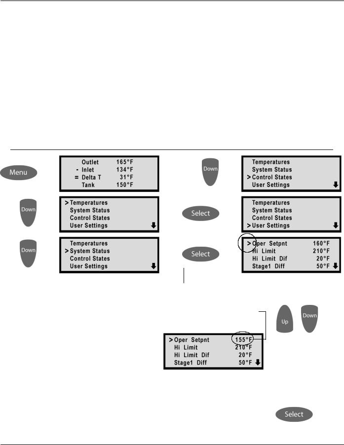
The sequence of UIM screen displays below is an example of how to navigate the menus to change the Operating Set Point.
Screen Display 1: shows the temperatures screen. This is the default display screen the UIM comes to rest at after approximately 60 seconds without any user input. The Menu button is touched once to enter the Menus screen containing 9 different sub menus.
Screen Displays 2 - 4: show the first four lines of the Menus screen. The Down button is touched several times to navigate to the User Settings menu on line four. The [ > ] sign on the left moves down one line each time the down button is touched. Also notice the down arrow that appears on the lower right corner, this indicates there are more menu items below the four lines currently being displayed. Up arrows appear on the top right corner when there are more menu items above.
Screen Display 5: the Select button is touched once to enter the User Settings menu.
Screen Display 6: shows the first four lines of the User Settings menu. Touching the Select button while the [ > ] sign is lined up with the “Oper Setpnt” menu item activates the adjustment mode for this menu item. (Oper Setpnt = Operating Set Point)
1 |
|
4 |
2 |
|
5 |
3 |
|
|
|
6 |
|
|
|
|
The Operating Set Point can now be changed. The [ > ] sign begins to flash on and off slowly indicating the adjustment mode is active for this setting. Touching the Up button once at this point would change the Operating Set Point 1 degree higher. Touching the Down
button once would lower the setting by 1 degree. Touch the Up or Down button continuously and the setting will start to ramp up or down rapidly.
Release the Up or Down button when the desired setting is reached.
Touch the Select button once to confirm and store the new value in memory.
AOS WPC - Technical Literature Dept |
8 of 72 |
Ashland City, TN © 2008 |
Servicing should only be performed by a Qualified Service Agent |
|
|

VF BOILER SERVICE MANUAL
UIM - USER INTERFACE MODULE - MENU SCREENS
At the top center of the UIM panel is the display LCD. This LCD is used to provide information to the user through menu activated screens. Within each of the screens, helpful context sensitive information can be displayed at any time by touching the “Help” button.
Touching the help button once more returns the user to the previous screen.
The 10 available screens are:
Menu Screen:
Displayed when the “Menu” button is touched. This screen is the selection point for the other menu screens.
Temperatures Screen (Default Screen):
Displays the temperatures sensed from the Outlet, Inlet, and optional remote Tank/Loop temperature probes. This screen also displays the calculated temperature rise (Outlet minus Inlet) through the boiler, sometimes referred to as the Delta T ( T). Shorted and disconnected probes will have “Short” and “----” displayed to the right. The Temperatures Screen is the default screen the boiler will come to rest at without any user input for approximately 60 seconds.
There are no adjustable user inputs available from this screen.
System Status Screen:
This screen is used to view the status of switch inputs and output states. An asterisk (*) is displayed next to the label when the status is “True” (the description is fulfilled). For example; if water is flowing, as detected by the flow switch, an asterisk (*) will appear in front of the Flow label (IE: *Flow).
There are no adjustable user inputs available from this screen.
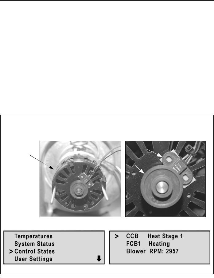
Control States Screen:
The CCB/FCB operating states of the boiler are displayed in this menu screen along with the actual blower motor rpm as relayed from a Hall Effect sensor (page 13) located inside the end cap of the blower motor. Blower rpm are displayed in real time. CCB and MCB are the same component on VF Boilers. See explanation for this and the FCB term on page 25.
There are no adjustable user inputs available from this screen.
User Settings Screen:
This screen is used to enter values for various user settings such as; the operating set point abbreviated Oper Setpnt, the Hi Limit (automatic high limit), pump post circulate time etc.
The Select button must be touched once to activate the adjustment mode for a user setting and again to confirm and store the new setting into memory.
Configuration Settings Screen
Displays the status of the SW1 and SW2 dip switches (pages 30 and 33) on the MCB.
There are no adjustable user inputs available from this screen.
AOS WPC - Technical Literature Dept |
9 of 72 |
Ashland City, TN © 2008 |
Servicing should only be performed by a Qualified Service Agent |
|
|
VF BOILER SERVICE MANUAL
UIM - USER INTERFACE MODULE - MENUS
Log & System Info Screen:
This screen displays the following:
•Elapsed hours of operation (Total time system has been powered up).
•Number of running minutes (Number of minutes system has been in the run mode).
•Number of heating cycles.
•kBtu rating of the boiler.
•Software revision of the CCB (MCB), FCB, and Config Key (see explanation on page 25).
There are no adjustable user inputs available from this screen.
Current Error Screen:
Displays the current error the system has detected, plus a timestamp of when the error occurred. (The timestamp is based on the elapsed hours value at the time the error occurred. It is displayed in hours and minutes). This error remains displayed as long as it is still valid. When cleared it is moved to the Error History Screen. The system will automatically jump to this screen when an error is detected. It will also go to this screen upon power-up if an error was still valid when power was turned off.
Errors are cleared (control system is reset) from this screen by touching the Select button.
There are no adjustable user inputs available from this screen.
Error History Screen:
This screen displays a list of the last 9 errors (with timestamps) that have occurred. The last error to occur is displayed first. The actual date and time of the event can be calculated by subtracting the error time stamp from the elapsed hours of operation in the Log & System Info Screen. This can be helpful when determining if the error is related to environmental or load conditions.
There are no adjustable user inputs available from this screen.
Reload Defaults Screen:
From this screen the user can restore the factory default values for screen adjustable configurations by touching the Select button. See page 70 for default values.
AOS WPC - Technical Literature Dept |
10 of 72 |
Ashland City, TN © 2008 |
Servicing should only be performed by a Qualified Service Agent |
|
|

VF BOILER SERVICE MANUAL
PRINCIPLES OF OPERATION
VF boilers do not have a gas orifice. The blower “pulls” gas from the gas valve into a Venturi attached to the suction (inlet) side of the blower (page 12). As the speed of the blower is increased the vacuum in the Venturi is also increased and more fuel gas and combustion air is supplied to the burner. This is the basic principle of how a VF boiler modulates firing rate.
VFD and Blower Operation
VF boilers have a small circuit board (Daughter Board) attached to the MCB circuit board
(page 25). The MCB controls a VFD (variable frequency drive) through the J24 socket connections on the Daughter Board (page 34). The VFD in turn powers the blower motor directly. The VFD controls blower speed precisely by modulating the frequency (Hz) of the power supplied to the blower motor. VFD output to the blower is a 3 Phase power supply.
Three conditions must be met before the VFD will start the blower:
1.120 VAC is supplied to the VFD 120 VAC input.
2.The MCB closes an enable/disable circuit that enables VFD operation.
3.The MCB sends a 1-10 VDC instruction to modulate blower speed.
The DC voltage instruction sent by the MCB is directly proportional to blower speed - higher
DC voltage = higher (faster) blower speed.
The blower power frequency (Hz) is also directly proportional to blower speed - higher frequency = higher (faster) blower speed. The output frequency is displayed on the VFD.
Ground |
Hot |
Neutral |
|
120 VAC input |
|
|
|
|
|
|
|
Output Frequency |
VFD |
|
|
||
|
R/L1 |
N |
Display |
|
|
|||
|
|
|
|
|
|
|
||
Blower Motor Wires |
3 Phase Power |
|
|
|
|
|||
Black |
White |
Red |
Variable Frequency |
|
|
|
|
|
|
|
|
Output To Blower |
|
|
|
|
|
U/T1 |
V/T2 W/T3 |
|
|
Low Voltage Terminal Strip |
||||
|
|
1-10 VDC Instruction |
||||||
|
|
|
|
|
|
Enable/Disable |
||
|
RC |
RA |
0V |
AI1 +5V DO |
LI1 |
LI2 |
LI3 |
LI4 +15 |
|
|
|
|
|
|
|
|
V |
|
|
1-10 VDC Speed Instruction |
Enable/Disable Circuit |
|||||
|
|
See the important service notes on page 34 |
||||||
AOS WPC - Technical Literature Dept |
11 of 72 |
Ashland City, TN © 2008 |
Servicing should only be performed by a Qualified Service Agent |
|
|

VF BOILER SERVICE MANUAL
PRINCIPLE OF OPERATION (CONT)
Venturi Operation - Gas Train
A Venturi is connected to the inlet side of the combustion blower on VF Boilers. The gas line from the outlet of the gas valve connects to the Venturi. The Venturi contains a cone shaped restrictor that constricts the air passage to the blower. As air enters the constriction point it’s velocity increases. A pressure drop occurs at this point and creates a negative (vacuum) pressure in the cavity between the cone shaped restrictor and the Venturi housing. This negative pressure “pulls” gas from the outlet of the gas valve into the blower where it is mixed with combustion air and then supplied to the burner.
As the blower speed is increased by the MCB (page 25) working in conjunction with the VFD
(page 11) the velocity of air flowing through the Venturi is also increased. This further increases the vacuum created by the Venturi and more fuel gas is pulled from the gas valve. This increases the firing rate (input Btu/hr) of the VF boiler. As the blower speed is decreased less fuel gas is supplied and the firing rate is reduced.
The MCB controls blower speed according to temperature demand. When system temperature sensed at the Controlling Probe (pages 62 and 63) is well below the VF Boiler’s Operating Set Point (pages 8 and 63) the MCB will run the blower at maximum speed =
100% firing rate. As system temperature approaches the VF Boiler’s Operating Set Point the
MCB will modulate the blower at slower speeds which subsequently reduces the firing rate. VF boilers are designed to modulate between 25% and 100%; a 4 to 1 turn down rate. See the illustration below.
Venturi Blower
Negative Pressure Area
Burner
Velocity Increases
Combustion Air At Constriction Point Blower Inlet
Pressure Drops
Negative Pressure Area
Fuel Gas
Gas Valve
VF Boiler Gas Train
Combustion |
Venturi |
Air Inlet |
|
Blower
Gas Valve
Burner Flange
Blower Outlet
AOS WPC - Technical Literature Dept |
12 of 72 |
Ashland City, TN © 2008 |
Servicing should only be performed by a Qualified Service Agent |
|
|
VF BOILER SERVICE MANUAL
PRINCIPLE OF OPERATION (CONT)
Blower Speed Verification - Hall Effect Sensor
The MCB (page 25) initiates blower operation by closing the VFD enable/disable circuit AND sending a 1-10 VDC speed instruction to the VFD (page 11) to energize the blower and to modulate blower speed.
The MCB monitors actual blower speed (rpm) to verify the speed dictated by the instruction has been achieved and to change the instruction as necessary. Actual blower speed information is relayed to the MCB by a “Hall Effect” sensor built into the end cap of the blower motor. Three wires connect between the J24 socket on the MCB Daughter Board (page 34) and the Hall Effect sensor to sense blower speed. See the images below.
Example: If the MCB has sent an 4.3 VDC instruction to the VFD to run the blower at 2500 rpm and the actual rpm relayed back from the Hall Effect sensor indicates the blower is running at 2400 rpm, the MCB will adjust (increase) the DC volt instruction slightly until the actual rpm information matches the instruction sent by the MCB. See VFD and Blower Speed operation on page 11.
The actual blower speed can be viewed in the Control States menu in real time through the UIM see pages 4 - 8 and 9 for instructions on how to navigate to this menu.
A round magnet is attached to the end of the blower shaft. The Hall Effect sensor is located in the magnetic field. The rotation of the magnet generates a signal in the sensor that is sent to the MCB. The MCB interprets this signal as blower speed (rpm) information.
Blower Motor |
|
|
Hall Effect Sensor |
With End Cap |
|
|
|
|
|
|
|
Removed |
|
|
Magnet |
|
|
|
Press Menu |
|
Navigate to Control States |
|
Press Select |
Control States Menu |
See the important service notes on page 34
AOS WPC - Technical Literature Dept |
13 of 72 |
Ashland City, TN © 2008 |
Servicing should only be performed by a Qualified Service Agent |
|
|
VF BOILER SERVICE MANUAL
PRINCIPLE OF OPERATION (CONT)
Config Key - Blower Speed Programming
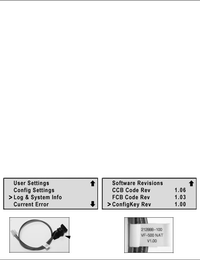
The Config Key is an 18” long cable with a plug on one end and an EEPROM memory chip sealed at the other. The Config Key plugs into the J23 socket on the MCB Daughter Board
(see pages 25 and 34). The memory chip contains blower speed programming data specific to the input Btu/hr and fuel type for each VF boiler. VF boilers are available in natural and propane gas and in three input Btu/hr sizes; 500,000 - 750,000 - 1,000,000. There are 6 different Config Keys. High altitude Config keys may be produced in the future.
Current production Config Keys (VF boilers) are certified up to 7700 foot elevation.
Each time the boiler is powered up the MCB reads and then stores the blower speed programming data from the Config Key into it’s own internal memory. The MCB then uses the data to modulate blower speed by sending 1-10 VDC instructions to the VFD (page 11). Modulating blower speed also modulates the firing rate on VF boilers (page 12).
There is a label at the end of the Config Key cable near the memory chip. This end of the cable is threaded into the wiring chase during production. The quickest way to verify the correct Config Key is installed is to navigate to the Log & System Info menu in the UIM pages 4 - 9) and compare the software revision number to the table below.
Current Config Key Software Revisions
Config Key |
VW/VB 500 |
VW/VB 750 |
VW/VB 1000 |
||||
Software |
|
|
|
|
|
|
|
Natural Gas |
Propane Gas |
Natural Gas |
Propane Gas |
Natural Gas |
Propane Gas |
||
Revisions |
|||||||
|
|
|
|
|
|
|
|
Rev # |
1.00 |
1.01 |
1.10 |
1.11 |
1.20 |
1.21 |
|
Even revision numbers are for natural gas models, odd numbers are for propane.
1.00 - 1.09 range for VW/VB 500 models
1.10 - 1.19 range for VW/VB 750 models
1.20 - 1.29 range for VW/VB 1000 models
Press Menu |
Log & System Info menu |
Navigate to Log & System Info |
|
Press Select |
Navigate to ConfigKey Rev |
Config Key |
Config Key Label |
 Memory Chip
AOS WPC - Technical Literature Dept |
14 of 72 |
Ashland City, TN © 2008 |
Servicing should only be performed by a Qualified Service Agent |
|
|
VF BOILER SERVICE MANUAL
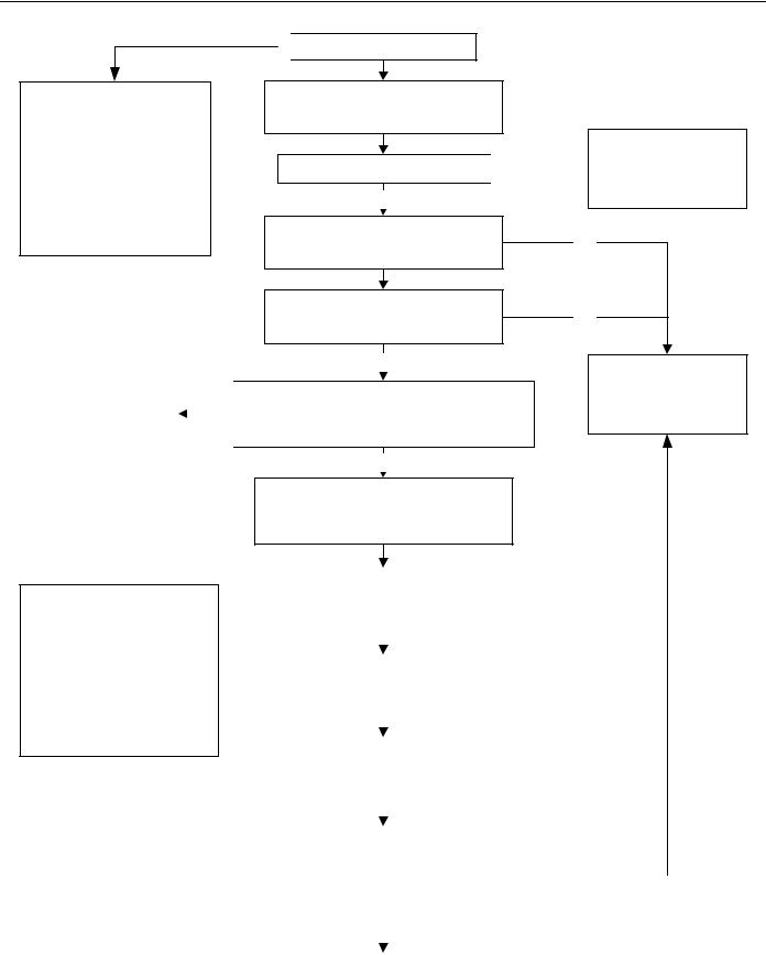
SEQUENCE OF OPERATION
 Call For Heat is Activated
EMC 5000 Control System compares the temperature read from controlling probe (Inlet or remote Tank/Loop) to the Operating Set Point.
If the temperature read is less than the Operating Set Point minus Stage 1 Differential AND the Enable/Disable (thermostat) circuit is closed a call for heat is activated
Boiler enters Service Mode |
|
|
|
|
|
|
|
|
|
and locks out. UIM displays |
|
|
|
|
|
|
NO |
|
|
Sequence Err |
|
|
|
|
|
|
|||
|
|
|
|
|
Error message |
|
|
|
|
|
|
|
|
|
MCB board applies power to pump relay
Pump Is Energized
Flow Switch Closes Contacts  NO
NO
YES
Low Blower Prover Switch
Contacts Verified Open
High Blower Prover Switch
Contacts Verified Open
YES
MCB Board
Closes VFD Enable/Disable Circuit Sends 1-10 VDC Speed Instruction to VFD
YES
Blower Is Energized By VFD Pre Purge State (approx 5000 rpm)
10-30 Seconds
Boiler enters Service Mode and locks out. UIM displays
No Flow
Error message
NO
NO
Boiler enters Service Mode and locks out. UIM displays
Blower Prov Stg1
Error message
NOTE
The events shown in this flow chart are in sequential order. The EMC 5000 is a multi-task control that performs some functions simultaneously. Only key events are shown in order to provide a general understanding of how the control operates. Event timings can vary depending on actual conditions.
|
Low Blower Prover Switch |
|
|
|
|
|||
|
|
|
NO |
|
||||
|
Contacts Verified Closed |
|
|
|
||||
|
|
|
|
|
||||
|
|
|
|
|
|
|
|
|
|
|
|
|
|
|
|
|
|
|
|
YES |
|
|
|
|
|
|
|
|
|
|
|
|
|
|
|
|
High Blower Prover Switch |
|
|
|
|
|||
|
|
|
NO |
|
||||
|
Contacts Verified Closed |
|
|
|
||||
|
|
|
|
|
||||
|
|
|
|
|
|
|
|
|
|
|
|
|
|
|
|
|
|
|
|
YES |
|
|
|
|
|
|
|
|
|
|
|
|
|
|
|
|
MCB Instructs VFD (1-10 VDC) |
|
|
|
|
|||
|
To Reduce Blower Speed |
|
|
|
|
|||
|
Ignition State (approx 2100 rpm) |
|
|
|
|
|||
|
|
|
|
|
|
|
|
|
|
|
|
|
|
|
|
|
|
|
High Blower Prover Switch |
|
|
|
|
|||
|
Contacts Verified Open |
|
|
|
|
|||
|
AND |
|
NO |
|
|
|||
|
|
|
||||||
|
Low Blower Prover Switch |
|
|
|
|
|||
|
|
|
|
|
||||
|
Contacts Remain Closed |
|
|
|
|
|||
|
|
|
|
|
|
|
|
|
|
|
|
|
|
|
|
|
|
|
|
YES |
|
|
|
|
|
|
|
|
|
|
|
|
|||
|
Next Page |
|
|
|
|
|||
|
|
|
|
|
|
|
|
|
AOS WPC - Technical Literature Dept |
15 of 72 |
|
|
Ashland City, TN © 2008 |
||||
Servicing should only be performed by a Qualified Service Agent
VF BOILER SERVICE MANUAL
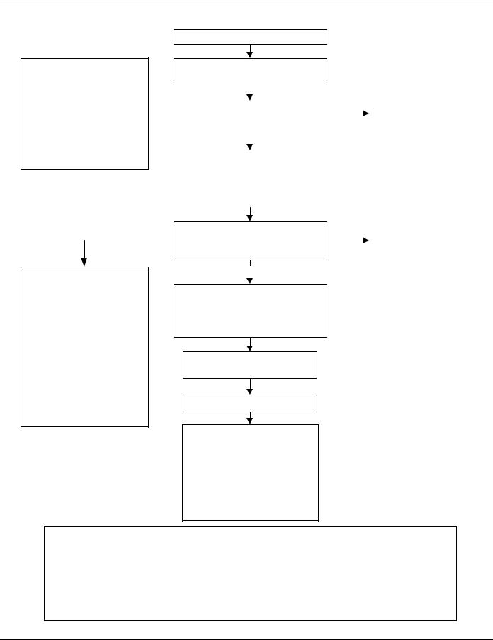
SEQUENCE OF OPERATION (CONT)
NOTE
The events shown in this flow chart are in sequential order. The EMC 5000 is a multi-task control that performs some functions simultaneously. Only key events are shown in order to provide a general understanding of how the control operates. Event timings can vary depending on actual conditions.
Previous Page
MCB Energizes Ignitor
Ignition State – 18 Seconds
|
|
|
|
|
|
|
|
|
|
|
|
|
|
|
|
|
|
|
|
|
Boiler enters Service Mode |
|
|
|
|
|
|
|
|
|
|
|
|
MCB Senses Minimum |
|
|
|
|
|
and locks out. UIM displays |
|||
|
|
|
NO |
|
|
|||||
|
2.7 AC Amps Through Ignitor |
|
|
|
|
Igniter Stg1 |
||||
|
|
|
|
|||||||
|
|
|
|
|
|
|||||
|
|
|
|
|
|
|
|
|
|
Error message |
|
|
|
|
|
|
|
|
|
|
|
|
|
YES |
|
|
|
|
|
|
|
|
|
|
|
|
|
|
|
||||
|
|
|
|
|
|
|
|
|
|
|
|
Gas Valve Is Energized |
|
|
|
|
|
|
|||
|
Fuel Gas Is Drawn Into |
|
|
|
|
|
|
|||
|
Blower Inlet By Venturi Assembly |
|
|
|
|
|
|
|||
|
Mixed With Combustion Air |
|
|
|
|
|
|
|||
Minimum Flame Sensing Current  2.5 µA (DC micro amps)
Detected From Flame Sensors
SERVICE NOTE
VF boilers utilize two flame sensors. One is positioned closer to the buner than the second to enable flame detection during low and high fire conditions.
The wiring from the two flame sensors is joined and connects to a single connection point on the MCB circuit board.
When the “Flame Stg1” error message is displayed remove, inspect, and clean both flame sensors.
YES
MCB Instructs VFD (1-10 VDC)
To Modulate Blower Speed
According To Load Conditions
Throughout Heating Cycle
Water Is Heated To
Operating Set Point
Gas Valve Is De-Energized
Blower Runs 25 Seconds
Post Purge State – Shuts Off.
Pump Runs Continuous Or
Programmed Post Circulate
Period Shuts Off.
Boiler Goes Into Standby
|
|
|
After 1 or 3 trials |
|
|
|
(SW1 dip switch 2 setting) |
NO |
|
|
Control enters Service Mode |
|
|
and locks out. UIM displays |
|
|
|
|
Flame Stg1 |
|
|
|
Error message |
|
|
|
|
SERVICE NOTE:
In standby and running modes the system constantly monitors the signals and the internal operation for faults.
Any detected fault will halt the heating sequence and shift the system to the service mode where the detected fault will be displayed.
AOS WPC - Technical Literature Dept |
16 of 72 |
Ashland City, TN © 2008 |
Servicing should only be performed by a Qualified Service Agent |
|
|

VF BOILER SERVICE MANUAL
START UP PROCEDURE
Prior To Start Up
In addition to normal supplies and hand tools necessary for installing and servicing water heaters and boilers the following tools and test equipment should be on hand. See the tool requirements page 3.
•A combustion analyzer capable of measuring draft pressure, CO, and CO2 or O2.
•True RMS Digital Multi Meter DMM capable of reading AC volts, DC volts, ohms,
DC micro amps µA, and frequency Hz.
•AC amp meter.
•TORX® T40 or 5mm hex wrench - for setting gas mixture at gas valve.
•3mm or 7/64in hex (allen) wrench - for setting gas mixture at gas valve.
•2 digital manometers for measuring supply and manifold gas pressures.
Firing Modes - Min/Max/Mod
When performing a Start Up on a VF boiler, the boiler’s firing mode must be set to the Min Mode (minimum firing - 25%) and the Max Mode (maximum firing - 100%). While the boiler is firing press the Menu button on the UIM (page 7). Using the Up and Down buttons scroll down until the > cursor to the left of the display is lined up with the User Settings menu and press the Select button. Scroll down to Mod Mode menu item and press the Select button again. The > cursor starts flashing on and off slowly indicating adjustment of this menu item is now possible. Use the up and down buttons to select between these three options:
•Min (forced minimum firing rate - 25%)
•Max (forced maximum firing rate - 100%)
•Mod (MCB automatic controlled firing rate - modulation mode)
Press the Select button for the desired option to confirm. The > cursor stops flashing and the boiler enters the firing mode selected.
The Min Mode and Max Mode are used for checking combustion during start up. Return the boiler to the Mod Mode after checking combustion. The boiler will automatically return to the Mod Mode after 10 minutes. Review the UIM and Menus information on pages 4 - 10.
Turning The Boiler Off
NEVER TURN THE BOILER OFF BY SECURING POWER WHILE IT IS FIRING. Repeated sudden stops while firing can damage the boiler. To shut down the boiler safely do one of the following so the boiler can go through a normal shut down sequence with post purge cycles:
•Lower the Operating Set Point to it’s lowest setting.
•Lower the set point of any external control in use to it’s lowest setting.
•Open the boiler’s 24 VAC Enable/Disable circuit manually (wires in the junction box on the back of the boiler). Be careful not to let the bare wire ends touch any grounded surface.
AOS WPC - Technical Literature Dept |
17 of 72 |
Ashland City, TN © 2008 |
Servicing should only be performed by a Qualified Service Agent |
|
|

VF BOILER SERVICE MANUAL
START UP PROCEDURE (CONT)
Start Up Procedure
1.Before starting the boiler, please review the boilers Instruction Manual supplied with the boiler. Ensure the water piping, gas line, controls, and venting have been installed per the instruction manual. Further information on water piping and controls is on pages 61 - 67 in this service manual.
2.Ensure the gas train shut off valve (see the image on page 23) in the boiler’s gas train is open.
3.Purge all air from the gas line to the boiler and ensure there are no gas leaks. Ensure the main supply gas valve is open.
4.Be certain that the system is full of water, that all air has been purged from the boiler, storage tank (s), and the water lines. Open both the supply and return water valves to the boiler. Ensure there are no water leaks.
5.Ensure the power supply meets the minimum requirements on page 68 in this manual. Ensure all control wiring (remote Tank/Loop probe - external Enable/Disable control) is run in a dedicated conduit per requirements on page 68.
6.Perform the power supply test outlined on page 40; correct any problems detected.
7.Prior to turning on the gas, proper sequence of most of the system can be verified. Close the manifold gas shut off valve (page 23), start the system and allow it to run through a heating cycle. It should stop when it checks for the flame and declare a fault.
This will verify that the pump, flow switch, igniter, VFD (variable frequency drive), gas valve, blower and low/ high blower prover switches are all functioning.
8.Drill a 7/16” hole in the side of the boot tee approximately 8" from back panel to insert the gas analyzer probe. The hole must be sealed upon completion of the start-up.
9.Open the main supply gas valve to the boiler.
10.Turn the boiler’s on/off switch on. Ensure the Operating Set Point is set high enough to activate a call for heat (page 8). If an external control is using the boiler’s Enable/Disable circuit (Aquastat, Boiler Sequencing Controller, EMS) ensure the external controls contacts are closed (page 65). If there is no external control using the boiler’s Enable/
Disable circuit ensure the two wires provided for this circuit are wire nutted together in the junction box on the back of the boiler. Review the controls section beginning on page
61 and refer to the wiring diagram on the boiler.
11.Allow the unit to run for at least 15 minutes before proceeding with the combustion analysis. Take a combustion sample and record CO and CO2 or O2 readings.
12.Attach a U tube manometer to supply gas pressure source at the boiler. Measure the supply gas pressure with a U tube manometer with the boiler firing in Max Mode. Set the boiler to Max Mode (Firing Modes - page 17). Ensure a minimum supply gas pressure of
4.0 " W.C. for natural gas or 11.0 " W.C. for propane is present with the boiler firing at
100%. Maximum supply gas pressures are 11.0 " W.C. natural gas and 13.8 " W.C. propane gas. Adjust supply gas pressure at the supply gas regulator as needed to maintain these supply gas pressure requirements.
AOS WPC - Technical Literature Dept |
18 of 72 |
Ashland City, TN © 2008 |
Servicing should only be performed by a Qualified Service Agent |
|
|

VF BOILER SERVICE MANUAL
START UP PROCEDURE (CONT)
Adjusting Manifold Gas
13.Set the boiler to Max Mode (Firing Modes - page 17). Check combustion readings using combustion analyzer. Compare CO2 readings taken to the Max Mode CO2 table below.
If CO2 readings are not within this range adjust as follows:
Remove the flat, round, blue plastic cap from the top of the boiler’s 24 VAC gas valve.
Using a 3mm (7/64”) hex wrench, turn the high fire adjustment screw under the cap counterclockwise to increase or clockwise to decrease gas flow and achieve the desired CO2 level. Reinstall blue cap when adjustments are complete. CO readings should be less than 200 ppm when firing in Max Mode.
14.Set the boiler to Min Mode (Firing Modes - page 17). Check combustion readings using combustion analyzer. Compare CO2 readings taken to the Min Mode CO2 table below. If
CO2 readings are not within this range adjust as follows:
Remove the small metal slotted cap near the outlet of the boiler’s 24 VAC gas valve. Using a TORX® T40 or a 5mm hex wrench turn the low fire adjustment screw under the cap clockwise to increase or counterclockwise to decrease gas flow and achieve the desired CO2 level. Reinstall the slotted cap when adjustments are complete. CO readings should be less than 100 ppm when firing in Min Mode.
Start Up Note: Adjust the settings in small increments (no more than 1/16 turn) and allow the combustion readings to stabilize for at least 3 minutes before readjusting. If required CO2 levels on start up form differ from levels in this manual adjust to levels shown on start up form.
Max Mode CO2 Levels
|
NATURAL GAS |
8.0 |
- 9.5% CO2 (CO < 200 PPM) |
|
|
|
|
|
PROPANE GAS |
9.5 |
- 10.5% CO2 (CO < 200 PPM) |
|
|
|
|
Min Mode CO2 Levels |
|
|
|
|
|
|
|
|
NATURAL GAS |
6.5 |
- 7.5% CO2 (CO < 100 PPM) |
|
|
|
|
|
PROPANE GAS |
7.5 |
- 8.5% CO2 (CO < 100 PPM) |
|
|
|
|
15.When start up procedure is complete return to the User Settings Menu and place the boiler back into Mod Mode firing mode (Firing Modes - page 17). Adjust the Operating Set Point in the User Settings Menu (page 8) to desired system temperature. Remove all test instruments and replace all plugs and caps.
16.Review page 67. The boiler must have a throttling valve on the outlet line. The boiler should have a bypass line with a throttling valve. Adjust the outlet valve to achieve a 20 - 40°F temperature rise through the boiler and the bypass valve to achieve a 120°F minimum inlet water temperature. Make these adjustments at 100% firing rate.
AOS WPC - Technical Literature Dept |
19 of 72 |
Ashland City, TN © 2008 |
Servicing should only be performed by a Qualified Service Agent |
|
|
VF BOILER SERVICE MANUAL
POOR COMBUSTION - IGNITION PROBLEMS
If the high and/or low fire CO2 combustion readings are not in accordance with the tables shown on page 19, the CO readings are high, or if the boiler is experiencing ignition failure or rough starting perform the following procedures:
Adequate Combustion - Proper Venting
1.Ensure there is an adequate supply of fresh air for combustion and the boiler is vented properly. DO NOT OVERLOOK THIS STEP. Lack of combustion air and improper venting is often the root cause for poor combustion.
Direct Vent Installations: If the boiler is direct vented ensure the intake air or the vent pipe is not restricted and neither has exceeded the maximum 70 equivalent feet. Ensure the vent and intake air terminations are positioned correctly so that vent gases are not recirculating to the intake air termination. Installation note: each 90° elbow is equivalent to 10 linear feet of pipe on VF boilers. If the boiler is in an equipment room with a door to the outdoors, temporarily disconnect the intake air pipe and prop open the equipment room door. Take combustion readings again to see if this corrects the problem.
Conventional Vent Installations: If the boiler is using room air for combustion ensure the vent pipe has not exceeded the 100’ maximum equivalent feet. Installation note: each 90° elbow is equivalent to 10 linear feet of pipe on VF boilers. Ensure the fresh air openings in the equipment room are adequately sized for the combined input Btu/hr rating of all conventionally vented gas fired appliances in the room. If the boiler is in an equipment room with a door to the outdoors - prop open the equipment room door. Take combustion readings again to see if this corrects the problem.
General venting guidelines are shown here. Refer to the Instruction Manual that came with the boiler for complete combustion air and vent installation information.
Direct Vent
Configurations
Installation Note:
VF Boilers are classified as Category IV appliances. AL29-4C vent material must be used for the exhaust vent on all installations.
Conventional Vent
Configurations
AOS WPC - Technical Literature Dept |
20 of 72 |
Ashland City, TN © 2008 |
Servicing should only be performed by a Qualified Service Agent |
|
|

VF BOILER SERVICE MANUAL
POOR COMBUSTION - IGNITION PROBLEMS (CONT)
Burner Inspection
2.Remove the burner and inspect the burner for any signs of damage or debris inside. If the burner is damaged or contaminated with debris - replace the burner. Check all gaskets in the burner/blower assembly for wear or damage. Replace any worn or damaged gaskets.
Firing Rate - Modulation Performance
3.The firing rate on VF boilers is modulated or controlled by blower speed (see pages 11 through 14). Ensure the correct Config Key (page 14) is installed for the input Btu/hr rating and fuel type of the boiler you are working on.
4.Verify the blower speed is acceptable during the following three operating states:
•Igniter warm up period - (AC amps can be detected through the igniter).
•Min Mode (Firing Modes - page 17).
•Max Mode (Firing Modes - page 17).
Start the boiler and check the three parameters listed below during the three operating states given above.
•DC voltage sent by the MCB at the VFD (page 11).
•Actual blower rpm as sensed by the Hall Effect sensor (page 13).
•Actual power frequency (Hz) on the VFD display (page 11).
Procedure
•Measure the DC volt instruction from the MCB at the VFD to ensure all wiring and connections between the J24 socket on the MCB Daughter Board and the VFD are intact (page 11).
•Check the actual blower rpm from the Control States Menu via the UIM display (page 13),
•Check the displayed Hz on the VFD (page 11).
Compare these values to those shown in the tables on page 22.
The actual blower rpm displayed by the UIM should be within 20% of the values given in the tables on page 22. The frequency should be within 5% of the values given in the tables page 22. The DC volt instruction should be within 1.0 VDC of the values given in the tables on page 22. If the actual values differ greatly from the values given in the tables on page 22 call our technical information center for further assistance at 800 527-
1953.
AOS WPC - Technical Literature Dept |
21 of 72 |
Ashland City, TN © 2008 |
Servicing should only be performed by a Qualified Service Agent |
|
|

VF BOILER SERVICE MANUAL
POOR COMBUSTION - IGNITION PROBLEMS (CONT)
VFD Operating Parameters
Approximate MCB/VFD operating parameters for natural gas models are shown in the first table below. Parameters for propane models are shown in the second table.
When combustion is poor, the firing rate of the boiler or blower speed is in question, or the boiler is experiencing rough starts or ignition failure compare the values given here to actual readings taken during the various operating states shown. Actual readings will vary somewhat but should be relatively close to what is shown here when the MCB and the VFD are operating properly.
Approximate Values Natural Gas |
VW/VB |
VW/VB |
VW/VB |
Blower Speed Control VFD |
500 |
750 |
1000 |
MCB Instruction Pre/Post Purge Mode Approx - VDC |
8.6 |
8.6 |
8.9 |
MCB Instruction Ignitor Warm Up Period Approx - VDC |
3.7 |
3.7 |
3.7 |
MCB Instruction Min Mode 25% Approx - VDC |
1.3 |
2.1 |
2.1 |
MCB Instruction Max Mode 100% Approx - VDC |
4.3 |
7.2 |
7.7 |
|
|
|
|
Blower Speed Pre/Post Purge Mode - Approx RPM |
5000 |
5000 |
5000 |
Blower Speed Ignitor Warm Up Period - Approx RPM |
2200 |
2200 |
2200 |
Blower Speed Min Mode 25% - Approx RPM |
800 |
1200 |
1250 |
Blower Speed Max Mode 100% - Approx RPM |
2500 |
4100 |
4500 |
|
|
|
|
Blower Power Freq Pre/Post Purge Mode - Approx Hz |
172 Hz |
172 Hz |
179 Hz |
Blower Power Frequency Ignitor Warm Up Period - Approx Hz |
75 Hz |
75 Hz |
75 Hz |
Blower Power Frequency Min Mode 25% - Approx Hz |
26 Hz |
41 Hz |
43 Hz |
Blower Power Frequency Max Mode 100% - Approx Hz |
85 Hz |
144 Hz |
155 Hz |
Approximate Values Propane Gas |
VW/VB |
VW/VB |
VW/VB |
Blower Speed Control VFD |
500 |
750 |
1000 |
MCB Instruction Pre/Post Purge Mode Approx - VDC |
8.6 |
8.6 |
8.9 |
MCB Instruction Ignitor Warm Up Period Approx - VDC |
3.7 |
3.7 |
3.7 |
MCB Instruction Min Mode 25% Approx - VDC |
1.4 |
2.1 |
2.4 |
MCB Instruction Max Mode 100% Approx - VDC |
4.3 |
7.7 |
7.7 |
|
|
|
|
Blower Speed Pre/Post Purge Mode - Approx RPM |
5000 |
5000 |
5000 |
Blower Speed Ignitor Warm Up Period - Approx RPM |
2200 |
2200 |
2200 |
Blower Speed Min Mode 25% - Approx RPM |
1000 |
1300 |
1400 |
Blower Speed Max Mode 100% - Approx RPM |
2500 |
4500 |
4500 |
|
|
|
|
Blower Power Freq Pre/Post Purge Mode - Approx Hz |
172 Hz |
171 Hz |
179 Hz |
Blower Power Frequency Ignitor Warm Up Period - Approx Hz |
74 Hz |
75 Hz |
75 Hz |
Blower Power Frequency Min Mode 25% - Approx Hz |
27 Hz |
43 Hz |
47 Hz |
Blower Power Frequency Max Mode 100% - Approx Hz |
85 Hz |
155 Hz |
155 Hz |
AOS WPC - Technical Literature Dept |
22 of 72 |
Ashland City, TN © 2008 |
Servicing should only be performed by a Qualified Service Agent |
|
|
 Loading...