


GNS-I-S Rev B
Installation & Service Manual
Models: 400 - 2100
WARNING: If the information in these instructions is not followed exactly, a fire or explosion may result causing property damage, personal injury or death.
--Do not store or use gasoline or other flammable vapors and liquids in the vicinity of this or any other appliance.
--WHAT TO DO IF YOU SMELL GAS
•Do not try to light any appliance.
•Do not touch any electrical switch; do not use any phone in your building.
•Immediately call your gas supplier from a near by phone. Follow the gas supplier’s instructions.
•If you cannot reach your gas supplier, call the fire department. -- Installation and service must be performed by a qualified
installer, service agency, or the gas supplier.
WARNING:
This manual supplies information for the installation, operation, and servicing of the appliance. It is strongly recommended that this manual and the Genesis Service Manual be reviewed completely before proceeding with an installation. Perform steps in the order given. Failure to comply could result in severe personal injury, death, or substantial property damage.
Save this manual for future reference.

Contents
HAZARD DEFINITIONS .................................................... |
2 |
PLEASE READ BEFORE PROCEEDING ........................ |
3 |
SAFETY INFORMATION................................................... |
4 |
THE GENESIS -- HOW IT WORKS................................ |
5-7 |
RATINGS ........................................................................... |
8 |
1. DETERMINE UNIT LOCATION |
|
Location of Unit .................................................................. |
9 |
Recommended Service Clearances.................................. |
9 |
Non-Combustible / Combustible Flooring ........................ |
10 |
Combustion Air Options .............................................. |
10-13 |
2. VENTING |
|
Before You Begin ............................................................. |
14 |
Vent System Options ....................................................... |
15 |
General Venting Information ............................................ |
16 |
Conventional Negative Draft Venting.......................... |
17-19 |
Vertical Vent/Ducted Air .............................................. |
20-22 |
Sidewall/Power Venting .............................................. |
23-25 |
Sidewall/Power Venting/Ducted Air.................................. |
26 |
Direct Vent/Sealed Combustion .................................. |
27-30 |
Outdoor Installation .......................................................... |
31 |
3. GAS CONNECTIONS |
|
Connecting to Gas Supply ............................................... |
32 |
Gas Pressure Test ........................................................... |
32 |
Checking Manifold Gas Pressure .................................... |
32 |
Combination Gas Valves.................................................. |
33 |
Checking Gas Supply Pressure ....................................... |
34 |
4. WATER CONNECTIONS |
|
Inlet & Outlet Connections ............................................... |
35 |
Relief Valve ...................................................................... |
35 |
Heating Unit Installations ............................................ |
36-37 |
5. ELECTRICAL CONNECTIONS |
|
Water Heater Operating Control Module ......................... |
38 |
Line Voltage Connections ................................................ |
39 |
Low Voltage Connections ................................................ |
39 |
External EMS Connection to Terminal Strip .................... |
39 |
Terminal Strip Connection Options ............................. |
39-40 |
Remote Mounting of Sensor......................................... |
40 |
6. STARTUP |
|
|
Check for Gas Leaks ....................................................... |
|
41 |
Check Thermostat Circuit(s) ............................................ |
|
41 |
Check Vent and Air Piping ............................................... |
|
41 |
Placing the Water Heater in Operation ............................ |
|
41 |
Start the Water Heater ..................................................... |
|
42 |
If Water Heater Does Not Start Correctly ........................ |
|
42 |
Set Water Heater Temperature........................................ |
|
42 |
Lighting Instructions ......................................................... |
|
43 |
7. OPERATING INFORMATION |
|
|
General............................................................................. |
|
44 |
User Interface................................................................... |
|
45 |
Powering Up the Control.................................................. |
|
46 |
View Menus................................................................. |
|
47-48 |
Errors and Warnings ................................................... |
|
47-49 |
LED Diagnostic Codes ..................................................... |
|
50 |
Hot Surface Ignition System ............................................ |
|
51 |
8. DOMESTIC WATER HEATERS |
|
|
Initial Setup of Maximum Water Flow .............................. |
|
52 |
Water Chemistry............................................................... |
|
53 |
Typical Water Heater Piping w/Storage Tank(s)......... |
|
54-55 |
Multiple Water Heater Piping w/Storage Tank(s) |
........ |
56-57 |
Pump Operation ............................................................... |
|
58 |
Minimum Water Temperatures (domestic hot water)....... |
59 |
|
9. MAINTENANCE..................................................... |
|
61-67 |
10. CONNECTION DIAGRAM.................................... |
|
68-69 |
11. LADDER DIAGRAM ............................................. |
|
70-71 |
12. WARRANTY ............................................................... |
|
75 |
Revision Notes .................................................. |
Back Cover |
|
Hazard definitions
The following defined terms are used throughout this manual to bring attention to the presence of hazards of various risk levels or to important information concerning the life of the product.
DANGER
WARNING
CAUTION CAUTION NOTICE
DANGER indicates an imminently hazardous situation which, if not avoided, will result in death or serious injury.
WARNING indicates a potentially hazardous situation which, if not avoided, could result in death or serious injury.
CAUTION indicates a potentially hazardous situation which, if not avoided, may result in minor or moderate injury.
CAUTION used without the safety alert symbol indicates a potentially hazardous situation which, if not avoided, may result in property damage.
NOTICE indicates special instructions on installation, operation, or maintenance that are important but not related to personal injury or property damage.
2
Installation & Service Manual
Please read before proceeding
Special instructions
NOTICE |
This is a gas appliance and should be installed |
|
by a licensed electrician and/or certified gas |
||
|
||
|
supplier. Service must be performed by a |
|
|
qualified service installer, service agency or |
|
|
the gas supplier. |
WARNING
WARNING
If the information in these instructions is not followed exactly, a fire or explosion may result causing property damage, personal injury, or death.
This appliance MUST NOT be installed in any location where gasoline or flammable vapors are likely to be present, unless the installation is such to eliminate the probable ignition of gasoline or flammable vapors.
Improper installation, adjustment, alteration, service or maintenance can cause injury or property damage. Refer to this manual for assistance or additional information, consult a qualified installer, service agency or the gas supplier.
Checking equipment –
Upon receiving equipment, check for signs of shipping damage. Pay particular attention to parts accompanying the appliances which may show signs of being hit or otherwise being mishandled. Verify total number of pieces shown on packing slip with those actually received. In case there is damage or a shortage, immediately notify the carrier.
WARNING Do not use this appliance if any part has been under water. The possible damage
to a flooded appliance can be extensive and present numerous safety hazards. Any appliance that has been under water must be replaced.
NOTICE |
The ceramic fiber material used in this |
|
appliance is an irritant; when handling or |
||
|
||
|
replacing the ceramic materials it is advisable |
|
|
that the installer follow these safety guides. |
REMOVAL OF COMBUSTION CHAMBER LINING OR BASE PANELS:
Avoid |
breathing |
dust |
and |
contact |
with |
skin |
||||
and eyes. |
|
|
|
|
|
|
|
|
|
|
• Use |
NIOSH |
certified |
dust |
respirator |
(N95). |
|||||
This type of respirator is based on the OSHA |
||||||||||
requirements for cristobalite at the time this |
||||||||||
document |
was |
written. |
|
Other |
types |
of |
||||
respirators |
may |
be |
needed |
depending |
on |
the |
job |
|||
site conditions. Current NIOSH recommendations |
||||||||||
can |
be |
found |
on |
the |
NIOSH |
website |
at |
|||
h t t p : / / w w w . c d c . g o v / n i o s h / h o m e p a g e . h t m l . |
||||||||||
NIOSH approved respirators, manufacturers, and |
||||||||||
phone numbers are also listed on this website. |
|
|
||||||||
• Wear |
long-sleeved, |
loose |
fitting clothing, |
gloves, |
||||||
and eye protection.
Apply enough water to the combustion chamber lining to prevent airborne dust.
Remove the combustion chamber lining from the appliance and place it in a plastic bag for disposal.
• NIOSH stated First Aid: Eye: Irrigate immediately. Breathing: Fresh air.
WARNING The combustion chamber insulation in this appliance contains ceramic fiber material. Ceramic fibers can be converted to cristobalite in very high temperature applications. The International Agency for Research on Cancer (IARC) has concluded, “Crystalline silica in the form of quartz or cristobalite from occupational sources is carcinogenic to humans (Group 1).” Normal operating temperatures in this appliance are below the level to convert ceramic fibers to cristobalite. Abnormal operating conditions would have to be created to convert the ceramic fibers in this appliance to cristobalite.
The ceramic fiber material used in this appliance is an irritant; when handling or replacing the ceramic materials it is advisable that the installer follow these safety guidelines.
Warranty –
Factory warranty (in this manual) does not apply to units improperly installed or improperly operated.
Experience has shown that improper installation or system design, rather than faulty equipment, is the cause of most operating problems.
1.Excessive water hardness causing a lime/scale build-up in the copper tube is not the fault of the equipment and is not covered under the manufacturer’s warranty (see Water Treatment and Water Chemistry).
2.Excessive pitting and erosion on the inside of the copper tube may be caused by too much water velocity through the tubes and is not covered by the manufacturer’s warranty (see Water Heater Flow Rates and Temperature
Rise for flow requirements).
3
Installation & Service Manual
Please read before proceeding
Safety information
Owner warning –
WARNING |
To minimize the possibility of serious |
|
personal injury, fire or damage to your |
||
|
The information contained in this manual is intended for use by qualified professional installers, service technicians, or gas suppliers.
NOTICE |
Consult and follow all local Building and |
|
Fire Regulations and other Safety Codes that |
||
|
||
|
apply to this installation. Consult local gas |
|
|
utility company to authorize and inspect all |
|
|
gas and flue connections. |
A gas appliance that draws combustion air from the equipment room where it is installed must have a supply of fresh air circulating around it during burner operation for proper gas combustion and proper venting.
unit, never violate the following safety rules.
1.This unit is only for use with the type of gas indicated on the rating plate.
2.If you smell gas
•shut off gas supply
•do not try to light any appliance
•do not touch any electrical switch; do not use any phone in your building
•immediately call your gas supplier from a neighbor’s phone. Follow the gas supplier’s instructions
•if you cannot reach your gas supplier, call the fire department
WARNING Should overheating occur or the gas supply fail to shut off, do not turn off or disconnect
the electrical supply to the pump. Instead, shut off the gas supply at a location external to the appliance.
Prevention of freezing –
Heat exchangers and headers damaged by freezing are not covered by warranty.
See Section 7, Operating Information - Freeze Protection for more information.
Codes –
The equipment shall be installed in accordance with those installation regulations in force in the local area where the installation is to be made. These shall be carefully followed in all cases. Authorities having jurisdiction shall be consulted before installations are made. In the absence of such requirements, the installation shall conform to the latest edition of the National Fuel Gas Code, ANSI Z223.1. Where required by the authority having jurisdiction, the installation must conform to American Society of Mechanical Engineers Safety Code for Controls and Safety Devices for Automatically Fired Boilers, ASME CSD-1. All boilers conform to the latest edition of the ASME Boiler and Pressure Vessel Code, Section IV. Where required by the authority having jurisdiction, the installation must comply with the Canadian Gas Association Code, CAN/CGA-B149.1 and/ or B149.2 and/or local codes. This appliance meets the safe lighting performance criteria with the gas manifold and control assembly provided, as specified in the ANSI standards for gas water heaters, ANSI Z21.10.3.
3.Water heaters are heat producing appliances. To avoid damage or injury, do not store materials against the appliance or the vent-air intake system. Use proper care to avoid unnecessary contact (especially children) with the appliance and vent-air intake components.
4.Never cover your unit, lean anything against it, store trash or debris near it, stand on it or in any way block the flow of fresh air to your unit.
5.UNDER NO CIRCUMSTANCES MUST FLAMMABLE MATERIALS SUCH AS GASOLINE OR PAINT THINNER BE USED OR STORED IN THE VICINITY OF THIS APPLIANCE, VENT-AIR INTAKE SYSTEM OR ANY LOCATION FROM WHICH FUMES COULD REACH THE APPLIANCE OR VENT-AIR INTAKE SYSTEM.
6.Appliance surfaces become hot during operation. Be careful not to touch hot surfaces. Keep all adults, children, and animals away from operation of the hot unit. Severe burns can occur.
7.You must take adequate care to prevent scald injury when storing water at elevated temperatures for domestic use.
8.This unit must have an adequate supply of fresh air during operation for proper gas combustion and venting.
9.Make sure all exhaust venting is properly installed and maintained. Improper venting of this unit could lead to increased levels of carbon monoxide.
10.Do not use this water heater if any part has been under water. Immediately call a qualified service technician to replace the appliance. The possible damage to a flooded water heater can be extensive and present numerous safety hazards. Any appliance that has been under water must be replaced.
11.Do not alter this unit in any way. Any change to this unit or its controls can be dangerous.
4

Installation & Service Manual
The Genesis - How it works...
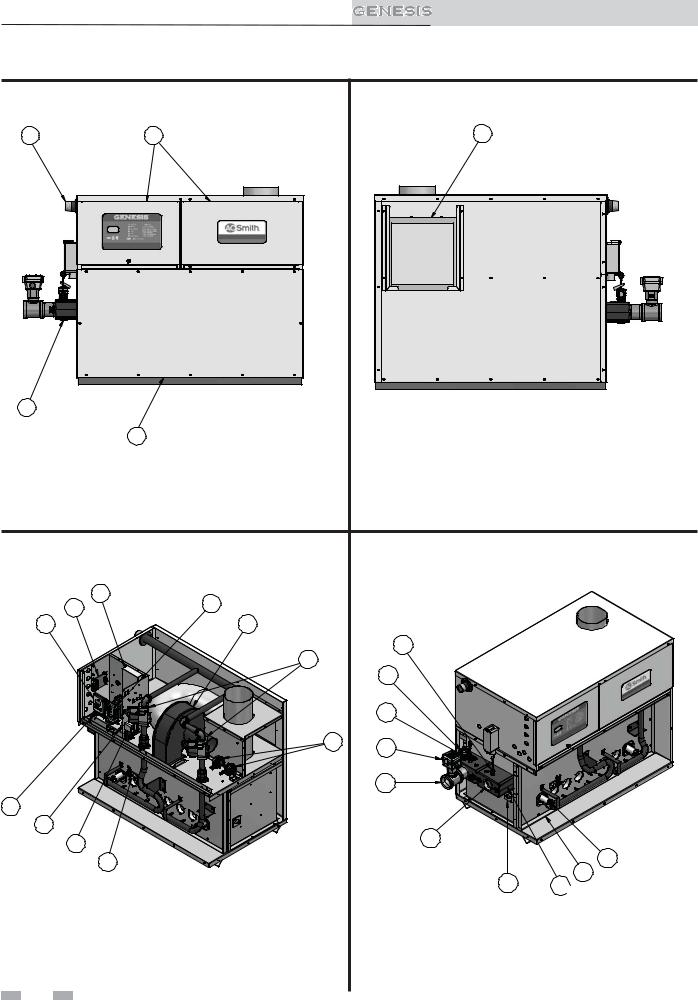
1.Heat exchanger
The heat exchanger allows system water to flow through specially designed tubes for maximum heat transfer. The glass lined headers and copper fined tubing are encased in a jacket that contains the combustion process.
2.Heat exchanger access cover
The heat exchanger access cover is a galvanized steel door which allows access for service, maintenance, and removal of the heat exchanger from inside the combustion chamber.
3.Blower
The blower pulls in and injects air into the individual burners along with gas from the gas manifold where the mix is burned inside the combustion chamber.
4.Gas valve
The gas valves (reference) have a dual purpose; changing the gas supply pressure to manifold pressure, and the reference side of the gas valve is designed to allow chamber pressure to change the volume of gas through the valve and measured as net manifold pressure. This is not a design to compensate for gas supply pressure issues.
5.Tank temperature sensor (not shown)
When connected, this sensor monitors tank temperature.
6.Outlet sensor
This sensor monitors the outlet water temperature.
7.Inlet temperature sensor
This sensor monitors inlet water temperature. If selected as the controlling sensor and a tank sensor is not connected, the appliance will maintain setpoint by adjusting the firing rate of the unit according to this sensor.
8.2-Stage electronic temperature control
The 2-stage electronic temperature control consists of a Liquid Crystal Display (LCD) for interactive prompting during programming and display of both sensed and assigned values. Programming is accomplished through the use of the three (3) programming buttons -- select, (+), and (-). This 2-stage electronic temperature control also controls the pump.
9.LED display board
The LED display board displays the status of the unit. LED’s are provided for prepurge, trial for ignition, Stage 1, Stage 2, ignition module status and alarm along with a RESET button
for resetting the ignition module.
10.Burner
Theburnerisaportedstainlesssteelconstructionwhichusesagas air mix to operate at a fixed input. Banks of burners turn on or off to vary the firing rate.
11.Water outlet (system supply)
The water outlet is a 2 or 2 1/2" (depending on model) pipe connection that supplies water to the tank with connections for a flow switch (see #25), a relief valve (see #22).
12.Water inlet (system return)
The water inlet is a 2 or 2 1/2" (depending on model) pipe connection that receives water from the tank and delivers it to the heat exchanger.
13.Gas supply pipe
The gas supply pipe on this appliance is 1 1/4 or 2" (depending on model) diameter NPT. Please reference the National Fuel Gas Code charts for connection details.
14.Hot surface ignition module
15.Air intake
Fresh air for combustion is drawn through a filter provided at the air intake, located at either the rear or right side of the appliance.
16.Line voltage terminal strip
The line voltage terminal strip provides a location to connect all of the line voltage (120 VAC) contact points to the unit.
17.Low voltage connection board(s)
The low voltage connection board provides a location to connect all of the low voltage devices to the appliance. This is where most of the external safety controls are connected.
18.Front doors - upper and lower
The front doors provide access to the gas train as well as the blower, burners and other key components for service and maintenance.
19.Hot surface igniter (HSI)
The hot surface igniter is a device that is used to ignite the air/gas mixture as well as monitor the performance of the flame during operation. This device acts as a flame sense electrode.
20.Flame inspection window (sight glass)
The flame inspection windows, located on either side of the appliance, allow for visual inspection of the burners and flame during operation.
21.Manual reset high limit sensor
This device monitors the outlet water temperature to ensure safe operation. If the temperature exceeds its setting (field adjustable), it will break the control circuit, shutting the appliance down.
22.Relief valve
The relief valve is a safety device that ensures the maximum pressure of the appliance is not exceeded. Water heaters operate on temperature and pressure and are shipped standard as 125 PSI and 210°F (98.9°C).
23.Power switch
The power switch is used to engage and disengage power to the appliance on the 120 VAC circuit.
24.Air pressure switch
The air pressure switch is a safety device which ensures proper blower operation. The air pressure switch is wired in series with the low voltage control circuit in such a way that if the fan does not engage or shuts down prematurely the device will break the control circuit and the unit will shut down.
25.Flow switch
The flow switch is a safety device that ensures flow through the heat exchanger during operation. This appliance is low mass and should never be operated without flow. The flow switch makes contact when flow is detected and allows the unit to operate. If flow is discontinued during operation for any reason the flow switch will break the control circuit and the unit will shut down.
26.Drain port(s)
The drain port(s) are located underneath the front header.
27.Manual shutoff valve (not shown)
Manual valve used to isolate the unit from the gas supply.
The hot surface ignition module controls the blower(s), hot surface igniter and gas valves. A status LED is also provided for flash codes used for the purpose of troubleshooting the unit.
5
Installation & Service Manual
The Genesis - How it works...
13 |
18 |
|
15 |
|
|
IMG00570 |
IMG00571 |
26 |
|
|
|
|
|
|
|
|
18 |
|
|
Models 400 - 750 Front View |
Models 400 - 750 Rear View |
|
14 |
9 |
|
|
17 |
|
||
8 |
3 |
|
|
|
4 |
7 |
|
|
22 |
||
|
|
||
|
|
6 |
|
|
24 |
25 |
|
|
|
||
|
|
11 |
|
16 |
|
IMG00573 |
|
|
|
||
23 |
|
12 |
|
21 |
IMG00572 |
||
10 |
|||
19 |
|||
|
2
20 1
Models 400 - 750 Right Side (inside unit)
Models 400 - 750 Left Side (inside unit)
6

Installation & Service Manual
The Genesis - How it works... (continued)
13 |
18 |
|
15 |
|
|
|
25 |
|
|
IMG00574 |
IMG00575 |
|
|
|
|
26 |
|
|
|
|
18 |
|
|
Models 1000 - 2100 Front View |
Models 1000 - 2100 Rear View |
|
14 |
24 |
3 |
|
|
|
|
||
|
|
|
|
|
17 |
9 |
|
4 |
7 |
|
|
|||
8 |
|
|
|
6 |
|
|
|
|
22
 11
11
16
IMG00577
23
21 |
IMG00576 |
12 |
|
|
|
||
19 |
|
1 |
10 |
|
20 |
||
|
|
2 |
|
|
|
|
Models 1000 - 2100 Right Side (inside unit)
Models 1000 - 2100 Left Side (inside unit)
7
Installation & Service Manual
Ratings
Genesis
AHRI Rating
Model Number |
Input |
|
|
Gross |
Net |
|
|
|
Output |
AHRI |
|||
|
MBH |
|
|
MBH |
Ratings |
|
|
(Note 3) |
|
|
|
Water, |
|
|
|
|
|
MBH |
||
Note: N = Natural, P = |
|
|
|
|
|
|
|
|
|
|
|
|
|
Propane |
Min |
|
Max |
|
(Note 1) |
|
|
|
|
|
|||
|
|
|
|
|
|
|
|
|
|
|
|
|
|
GWH0400(N,P) |
250 |
|
399 |
339 |
295 |
|
|
|
|
|
|
|
|
GWH0500(N,P) |
250 |
|
500 |
425 |
370 |
|
GWH0650(N,P) |
350 |
|
650 |
553 |
481 |
|
GWH0750(N,P) |
400 |
|
750 |
638 |
555 |
|
GWH1000(N,P) |
360 |
|
990 |
842 |
732 |
|
GWH1250(N,P) |
720 |
|
1260 |
1071 |
931 |
|
GWH1450(N,P) |
720 |
|
1440 |
1224 |
1064 |
|
GWH1800(N,P) |
720 |
|
1800 |
1530 |
1330 |
|
GWH2100(N,P) |
990 |
|
2070 |
1760 |
1530 |
|
HLW |
LOW LEAD CONTENT |
Other Specifications
Appliance |
|
|
Air / Vent |
Water |
Water |
Gas |
Sizes |
Content |
Connections |
Connections |
|
Gallons |
|
|
(Note 2) |
|
|
|
|
|
|
|
|
1.6 |
2" |
1-1/4" |
6" |
1.7 |
2" |
1-1/4" |
6" |
2.0 |
2" |
1-1/4" |
8" |
2.1 |
2" |
1-1/4" |
8" |
2.2 |
2-1/2" |
2" |
10" |
2.6 |
2-1/2" |
2" |
12" |
2.9 |
2-1/2" |
2" |
12" |
3.3 |
2-1/2" |
2" |
12"/14" |
3.6 |
2-1/2" |
2" |
12"/14" |
NOTICE Maximum allowed working pressure is located on the rating plate.
Notes:
1.The ratings are based on standard test procedures prescribed by the United States Department of Energy.
2.Genesis models require special gas venting. Use only the vent materials and methods specified in the Genesis Installation and Operation Manual.
3.The Genesis water heater is orificed for operation up to 2000 feet altitude, and including up to 4,500 feet, with no field adjustments. The appliance will de-rate by 4% for each 1000 feet above sea level up to 4,500 feet. Consult the factory for installations above 4,500 feet elevation.
8
1 Determine unit location
Location of unit
This unit meets the safe lighting performance criteria with the gas manifold and control assembly provided, as specified in the ANSI standards for gas-fired units and ANSI Z21.10.3/ CSA 4.3 - latest edition.
1.Maintain all clearances from combustible construction when locating appliance. See Clearances from Combustible Construction, this page.
2.Locate the appliance so that if water connections should leak, water damage will not occur. When such locations cannot be avoided, it is recommended that a suitable drain pan, adequately drained, be installed under the unit. The pan must not restrict combustion airflow. Under no circumstances is the manufacturer to be held responsible for water damage in connection with this unit, or any of its components.
3.The appliance must be installed so that the ignition system components are protected from water (dripping, spraying, rain, etc.,) during appliance operation and service (circulator replacement, control replacement, etc.,).
4.Appliances located in a residential garage and in adjacent spaces that open to the garage and are not part of the living space of a dwelling unit must be installed so that all burners and burner ignition devices have a minimum clearance of not less than 18" (46 cm) above the floor. The appliance must be located or protected so that it is not subject to physical damage by a moving vehicle.
5.DO NOT install this appliance in any location where gasoline or flammable vapors are likely to be present.
6.The appliance must be installed on a level floor.
7.Combustible floor installation:
a.Models 400 - 750 require an approved floor kit for installation on combustible flooring (reference Table 1A).
b. Models 1000 - 2100 are approved for installation on combustible flooring without a floor kit. Note: Concrete block over wood flooring is not considered non-combustible.
8.DO NOT install this appliance directly on carpeting or other combustible material.
9.Maintain required clearances from combustible surfaces, reference the Indoor Clearances from Combustible Construction Section, this page.
10.For outdoor models, you must install an optional vent cap. Instructions for mounting the vent cap are included in the venting section of this manual. Do not install outdoor models directly on the ground. You must install the outdoor unit on a concrete, brick, block, or other
non-combustible pad. Outdoor models have additional special location and clearance requirements. See Outdoor Installation Venting, page 31. A wind proof cabinet
protects the unit from weather.
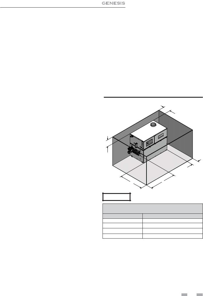
Indoor clearances from combustible construction
Maintain minimum specified clearances for adequate operation. Allow sufficient space for servicing pipe connections, pump and other auxiliary equipment, as well as the unit. See rating plate for specific service clearance requirements.
|
|
Installation & Service Manual |
|
|
|
Right Side |
3" |
(7.5 cm) |
Rear |
3" |
(7.5 cm) (3" min. from any surface)* |
Left Side |
6" (15 cm) (24" (0.61 m) suggested for |
|
|
service) |
|
Front |
Alcove* (30" (0.76m) suggested for service) |
|
Top |
3" |
(7.5 cm) |
Flue |
1" |
(25.4 mm) |
Hot Water Pipes 1" |
(25.4 mm) |
|
*An Alcove is a closet without a door. Thirty-six inches (36") to rear required for outdoor installation.
Note: No additional clearance is needed on the right side of the unit for the observation port. An observation port is located on both the right and left side of the unit.
Figure 1-1_Indoor clearances from combustible construction
3" MIN REAR
3" |
|
|
|
|
MIN |
|
|
|
|
TOP |
|
|
|
|
|
|
3" |
IMG00578 |
|
|
|
MIN |
|
|
|
|
RIGHT |
|
|
|
|
SIDE |
|
|
|
30" |
6" |
|
|
|
MIN |
|
||
|
MIN |
|
||
|
LEFT |
|
||
|
FRONT |
|
||
|
SIDE |
|
||
|
|
|
||
NOTICE |
Clearances |
from combustible construction |
||
are noted on the appliance rating plate. |
||||
|
||||
|
TABLE - 1A |
|
||
|
COMBUSTIBLE FLOOR KITS |
|
||
Model |
|
Kit Number |
|
|
400 |
|
9910107000 |
|
|
500 |
|
9910107001 |
|
|
650 |
|
9910107002 |
|
|
750 |
|
9910107003 |
|
|
Freeze protection
Although these units are CSA International design-certified for outdoor installations, such installations are not recommended in areas where the danger of freezing exists. You must provide proper freeze protection for outdoor installations, units installed in unheated mechanical rooms or where temperatures may drop to the freezing point or lower. If freeze protection is not provided for the system, a low ambient temperature alarm is recommended for the mechanical room. Damage to the unit by freezing is non-warrantable.
9
Installation & Service Manual
1 Determine unit location
Anytime the temperature of any sensor drops below 34°F, the control turns on the pump contact.
Location
Locate indoor water heaters in a room having a temperature safely above freezing [32°F (0°C)].
CAUTION |
A mechanical room operating under a negative |
|
draft pressure may experience a down draft in |
|
the flue of a water heater when it is not firing. |
|
The cold outside air pulled down the flue |
|
may freeze a heat exchanger. This condition |
|
must be corrected to provide adequate freeze |
|
protection. |
Outdoor installation
A snow screen should be installed to prevent snow and ice accumulation around the unit or its venting system.
Shut-down and draining
If for any reason, the unit is to be shut off, the following precautionary measures must be taken:
1.Shut off gas supply.
2.Shut off water supply.
3.Shut off electrical supply
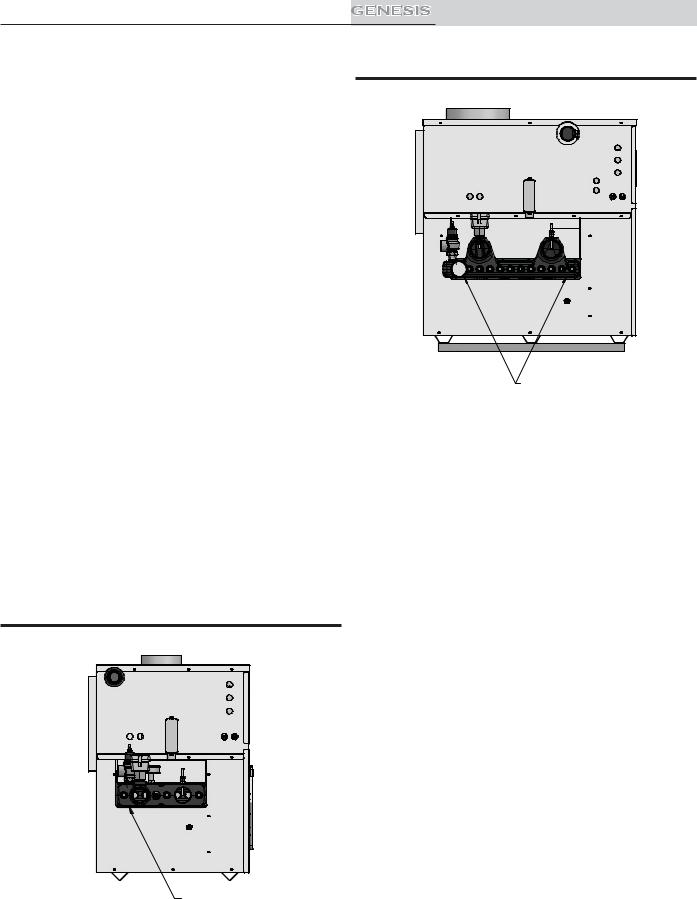
4.Drain the unit completely. Remove one threaded plug or bulbwell from the inlet side of the front header and one from the outlet side of the front header on the heat exchanger. Blow all water out of the heat exchanger (see FIG.'s 1-2A and 1-2B).
5.Drain pump and piping.
Figure 1-2A_Drain the unit_Models 400 -750
DRAIN PLUG
Figure 1-2B_Drain the unit_Models 1000 - 2100 |
DRAIN PLUG (2X)
Combustion and ventilation air
Provisions for combustion and ventilation air must be in accordance with Air for Combustion and Ventilation, of the latest edition of the National Fuel Gas Code, ANSI Z223.1, in Canada, the latest edition of CAN/CGA-B149 Installation Code for Gas Burning Appliances and Equipment, or applicable provisions of the local building codes.
Provide properly-sized openings to the equipment room to assure adequate combustion air and proper ventilation when the unit is installed with conventional venting or sidewall venting.
Combustion air options
CAUTION |
Under no circumstances should the |
||
equipment room ever be under a |
|||
|
|||
|
negative pressure. |
Particular care |
|
|
should be taken where exhaust fans, |
||
|
attic fans, clothes dryers, compressors, |
||
|
air handling units, etc., may take away |
||
|
air from the unit. |
|
|
This unit has four combustion air options.
1. Outside Combustion Air, No Ducts
You can direct outside combustion air to this unit using either one or two permanent openings (see FIG. 1-3).
One Opening
The opening must have a minimum free area of one square inch per 3000 Btu input (7 cm2 per kW). You must locate this opening within 12" (30 cm) of the top of the enclosure.
 10
10 
Installation & Service Manual
1 Determine unit location
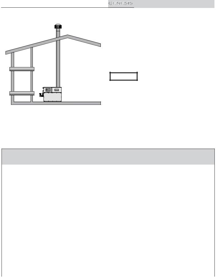
2. Outside Combustion Air, Using Ducts
You can direct outside combustion air to this unit using two air ducts to deliver the air to the equipment room (see FIG. 1-4).
Each of the two openings must have a minimum free area of one square inch per 2000 Btu input (11cm2 per kW).
3. Combustion Air from Interior Space
You can direct combustion air to this unit using air from an adjoining interior space. You must provide two openings from the equipment room to the adjoining room (see FIG. 1-5).
Each of the two openings must have a net free area of one square inch per 1000 Btu input (22cm2 per kW), but not less than 100 square inches (645cm2).
IMG00579
Figure 1-3_Outside Combustion Air - Single Opening
Two Openings
The combustion air opening must have a minimum free area of one square inch per 4000 Btu/hr input (5.5 cm2 per kW). You must locate this opening within 12" (30 cm) of the bottom of the enclosure (see FIG. 1-4).
The ventilation air opening must have a minimum free area of one square inch per 4000 Btu/hr input (5.5 cm2 per kW). You must locate this opening within 12" (30 cm) of the top of the enclosure.
IMG00581 |
Figure 1-5_Combustion Air from Interior Space
IMG00580
Figure 1-4_Outside Combustion Air - Two Openings
 11
11 
Installation & Service Manual
1 Determine unit location
IMG00582 |
Figure 1-6_Outside Combustion Air Through Ducts
4. Outside Combustion Air - Using Direct Venting
With this option, you can connect combustion air vent piping directly to the unit. See the information under Direct Venting starting on page 27 for specific information regarding this option.
All dimensions are based on net free area in square inches. Metal louvers or screens reduce the free area of a combustion air opening a minimum of approximately 25%. Check with louver manufacturers for exact net free area of louvers. Where two openings are provided, one must be within 12" (30 cm) of the ceiling and one must be within 12" (30 cm) of the floor of the equipment room. Each opening must have a minimum net free area as specified in TABLE 1B. Single openings shall be installed within 12" (30 cm) of the ceiling.
CAUTION The combustion air supply must be completely free of any flammable vapors
that may ignite or chemical fumes which may be corrosive to the appliance. Common corrosive chemical fumes which must be avoided are fluorocarbons and other halogenated compounds, most commonly present as refrigerants or solvents, such as Freon, trichlorethylene, perchlorethylene, chlorine, etc. These chemicals, when burned, form acids which quickly attack the heat exchanger finned tubes, headers, flue collectors, and the vent system. The result is improper combustion and a nonwarrantable, premature unit failure.
TABLE - 1B
MINIMUM RECOMMENDED COMBUSTION
AIR SUPPLY TO EQUIPMENT ROOM
|
*Outside Air from |
|
Inside Air from |
Inside Air from |
||||
Model |
2 Openings Directly from |
*Outside Air from |
2 Ducts Delivered from |
2 Ducts Delivered from Interior |
||||
Outdoors |
1 Opening Directly |
Outdoors |
Space |
|||||
Number |
||||||||
Top |
Bottom |
from Outdoors, in2 |
Top |
Bottom |
Top |
Bottom |
||
|
||||||||
|
Opening, in2 |
Opening, in2 |
|
Opening, in2 |
Opening, in2 |
Opening, in2 |
Opening, in2 |
|
400 |
100 |
100 |
133 |
200 |
200 |
400 |
400 |
|
(645 cm2) |
(645 cm2) |
(858 cm2) |
(1291 cm2) |
(1291 cm2) |
(2581 cm2) |
(2581 cm2) |
||
500 |
125 |
125 |
167 |
250 |
250 |
500 |
500 |
|
(806 cm2) |
(806 cm2) |
(1077 cm2) |
(1613 cm2) |
(1613 cm2) |
(3226 cm2) |
(3226 cm2) |
||
650 |
163 |
163 |
217 |
325 |
325 |
650 |
650 |
|
(1052 cm2) |
(1052 cm2) |
(1400 cm2) |
(2097 cm2) |
(2097 cm2) |
(4194 cm2) |
(4194 cm2) |
||
750 |
188 |
188 |
250 |
375 |
375 |
750 |
750 |
|
(1213 cm2) |
(1213 cm2) |
(1613 cm2) |
(2420 cm2) |
(2420 cm2) |
(4839 cm2) |
(4839 cm2) |
||
1000 |
248 |
248 |
330 |
495 |
495 |
990 |
990 |
|
(1600 cm2) |
(1600 cm2) |
(2129 cm2) |
(3194 cm2) |
(3194 cm2) |
(6388 cm2) |
(6388 cm2) |
||
1250 |
315 |
315 |
420 |
630 |
630 |
1260 |
1260 |
|
(2032cm2) |
(2032cm2) |
(2710 cm2) |
(4065 cm2) |
(4065 cm2) |
(8130 cm2) |
(8130 cm2) |
||
1450 |
360 |
360 |
480 |
720 |
720 |
1440 |
1440 |
|
(2323cm2) |
(2323cm2) |
(3097 cm2) |
(4646 cm2) |
(4646 cm2) |
(9291 cm2) |
(9291 cm2) |
||
1800 |
450 |
450 |
600 |
900 |
900 |
1800 |
1800 |
|
(2903cm2) |
(2903cm2) |
(3871 cm2) |
(5807 cm2) |
(5807 cm2) |
(11614 cm2) |
(11614 cm2) |
||
2100 |
518 |
518 |
690 |
1035 |
1035 |
2070 |
2070 |
|
(3342cm2) |
(3342cm2) |
(4452 cm2) |
(6678 cm2) |
(6678 cm2) |
(13356 cm2) |
(13356 cm2) |
||
*Outside air openings shall directly communicate with the outdoors. When combustion air is drawn from the outside through a duct, the net free area of each of the two openings must have twice (2 times) the free area required for Outside Air/2 Openings. The above requirements are for the water heater only; additional gas fired appliances in the equipment room will require an increase in the net free area to supply adequate combustion air for all appliances.
 12
12 

Installation & Service Manual
1 Determine unit location (continued)
Exhaust fans
Any fan or equipment which exhausts air from the equipment room may deplete the combustion air supply and/or cause a down draft in the venting system. Spillage of flue products from the venting system into an occupied living space can cause a very hazardous condition that must be immediately corrected. If a fan is used to supply combustion air to the equipment room, the installer must make sure that it does not cause drafts which could lead to nuisance operational problems with the unit.
Vertical Vent/Air, Horizontal Vent/Air, and Direct Vent venting systems have specific requirements for combustion air ducts from the outside which are directly connected to the unit. See the requirements for combustion air duct in the venting section.
NOTICE |
Use of filters having MERV (Minimum |
Efficiency Reporting Value) ratings higher than |
|
|
4 is not recommended. Higher efficiency |
|
low-micron filters can limit combustion |
|
air leading to either nuisance problems or |
|
potential component damage if used over |
|
prolonged periods of time. Filters having |
|
a MERV rating of 5 to 6 may be used |
|
on a limited basis during the construction |
|
phase of a project provided they are replaced |
|
once filter loading becomes apparent. After |
|
the construction phase is completed, it is |
|
recommended that the filter be changed to a |
|
4 or lower MERV disposable type filter. |
Combustion air filter
This unit has a standard air filter located at the combustion air inlet. This filter helps ensure clean air is used for the combustion process. Check this filter every month and replace when it becomes dirty. The filter size on Models 400 - 750 is 12" x 12" x 1" (30.5cm x 30.5cm x 2.5cm) and 16" x 16" x 1" (40.6cm x 40.6cm x 2.5 cm) on Models 1000 - 2100. You can find these commercially available filters at any home center or HVAC supply store.
For convenience and flexibility, you can direct the combustion air inlet from either the back or right side of the unit. To arrange the combustion air inlet for side entry, follow the steps below:
1.Remove the metal panel from the unit’s side wall (see FIG. 1-7).
2.Remove screws from the air filter/bracket assembly.
3.Move the filter/bracket assembly from the rear of unit to the side opening (see FIG. 1-8).
4.Attach filter/bracket assembly to the unit’s side using the pre-drilled screw holes.
5.Attach the metal panel to the rear combustion air opening to seal it off.
Figure 1-7_Metal Panel Covering Side Combustion |
Figure 1-8_Moving Air Filter / Bracket Assembly from |
Air Inlet |
Rear of Unit to Side |
|
|
NOTICE
CAUTION
During construction the air filter should be checked more frequently to ensure it does not become clogged with combustion dirt and debris.
Sustained operation of an appliance with a clogged filter may result in nuisance operational problems, bad combustion, and non-warrantable component failures.
 13
13 
Installation & Service Manual
2 Venting
BEFORE YOU BEGIN
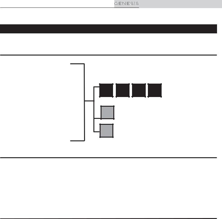
Identify your appliance’s vent system:
This manual covers venting requirements for CAT I models and CAT IV vent materials. Be sure to correctly identify the type of vent system your appliance requires before proceeding.
GWH0400(N,P) |
Venting options: |
|
||
GWH0500(N,P) |
|
|||
A |
B C D |
|
||
GWH0650(N,P) |
= B-Vent Material |
|||
GWH0750(N,P) |
||||
|
|
CAT I |
||
GWH1000(N,P) |
E |
|
|
|
GWH1250(N,P) |
= Direct Vent Options |
|||
GWH1450(N,P) |
||||
|
CAT IV |
|
||
GWH1800(N,P) |
F = Outdoor Vent Option |
|||
GWH2100(N,P) |
||||
DANGER |
Failure to use correct venting materials can result in loss of life from flue gas spillage into working or living |
|
space. |
|
Venting Category Definitions: (Reference National Fuel Gas Code ANSI Z223.1)
CAT I: Negative pressure non-condensing
An appliance that operates with a non-positive vent static pressure with a vent gas temperature that avoids excessive condensate production in the vent.
CAT IV: Positive pressure condensing
An appliance that operates with a positive vent static pressure with a vent gas temperature that may cause excessive condensate production in the vent.
CAT IV Flue pipe materials
The following manufacturers supply flue materials suitable for these models when installed as CAT IV. All materials are made with AL29-4C stainless steel.
Heat-Fab Inc., Saf-T CI Vent with AL29-4C stainless steel
Protech Systems Inc., Fas N Seal Vent with AL29-4C stainless steel
Metal-Fab Inc., Corr/Guard Vent with AL29-4C stainless steel
Or other listed Category IV vent systems suitable for a condensing, positive pressure, gas fired appliance.
A Category IV flue MUST have all vent joints and seams sealed gastight and have provisions for a drain to properly collect and dispose of condensate that may occur in the venting system.
 14
14 
Installation & Service Manual
2 Venting (continued)
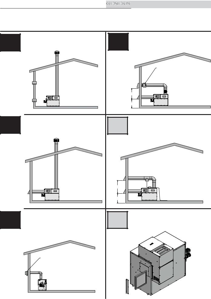
Vent system options: (Note: Installations shown below are representative, actual installations may vary from those shown.)
A |
This option uses a vertical rooftop flue termination |
D |
This option uses a powered vent assembly to |
with air supplied from the equipment room - see |
exhaust the flue products out a sidewall with air |
||
page 17. |
supplied by a pipe from the sidewall - see page 26. |
||
CONVENTIONAL NEGATIVE |
SIDEWALL/POWER VENTING/ |
||
DUCTED AIR |
|
||
DRAFT VENTING |
|
||
|
|
||
|
|
|
NOTE: CAT I B-VENT MATERIALS MAY BE USED WHEN THE |
|
|
|
POWERED VENT IS CONNECTED DIRECTLY TO THE OUTSIDE |
|
|
|
VENT CAP. IF THE POWERED VENT IS NOT CONNECTED |
|
|
|
DIRECTLY TO THE OUTSIDE VENT CAP, THEN CAT IV - AL29-4C |
|
|
|
VENT MATERIALS MUST BE USED FROM THE POWERED VENT |
|
|
|
TO THE OUTSIDE VENT CAP. |
3' MIN
12" MIN
IMG00580 |
IMG00584 |
B |
This option uses a vertical conventional vent for |
E |
This option uses a sealed AL29-4C flue and a |
flue products with air supplied by a pipe from the |
separate combustion air pipe to the outdoors. |
||
sidewall or rooftop - see page 20. |
This system terminates both the flue and |
||
|
|
|
combustion air inlet in the same pressure zone |
VERTICAL VENT/DUCTED AIR |
|
- see page 27. |
|
|
|
DIRECT VENT/SEALED |
|
|
|
COMBUSTION |
|
|
|
|
3' |
|
|
|
|
MIN |
|
|
|
|
12" |
|
|
|
|
MIN |
|
|
|
IMG00583 |
|
IMG00585 |
|
|
|
|
|
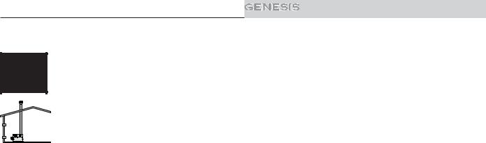
C |
This option uses a powered vent |
assembly |
F |
This option uses the installation of a special air |
to exhaust the flue products out a sidewall |
inlet / vent cap on top of the unit - see page 31. |
|||
vent termination with air supplied |
from the |
|
||
|
equipment room - see page 23. |
|
|
|
SIDEWALL/POWER VENTING |
OUTDOOR VENTING |
|
NOTE: CAT I B-VENT MATERIALS MAY BE USED WHEN THE
POWERED VENT IS CONNECTED DIRECTLY TO THE OUTSIDE
VENT CAP. IF THE POWERED VENT IS NOT CONNECTED
DIRECTLY TO THE OUTSIDE VENT CAP, THEN CAT IV - AL29-4C
VENT MATERIALS MUST BE USED FROM THE POWERED VENT
TO THE OUTSIDE VENT CAP.
 15
15 

Installation & Service Manual
2 Venting
General information
You must supply adequate combustion and ventilation air to this unit. You must provide minimum clearances for the vent terminal from adjacent buildings, windows that open, and building openings. Follow all requirements set forth in the latest edition of the National Fuel Gas Code, ANSI Z223.1, in Canada, the latest edition of CAN/CGA Standard B149 Installation Code for Gas Burning Appliances and Equipment or applicable local building codes. Vent installations for connection to gas vents or chimneys must be in accordance with “Venting of Equipment” of the above-mentioned standards.
NOTICE |
Examine the venting system at least once each year. Check all joints and vent pipe connections for tightness. Also |
|
check for corrosion or deterioration. If you find any problems, correct them at once. |
||
|
Venting support
Support horizontal portions of the venting system to prevent sagging. Provide an upward slope of at least 1/4 inch per foot (21mm/m) on all horizontal runs from the unit to the vertical flue run or to the vent terminal on sidewall venting installations.
Do not use an existing chimney as a raceway if another appliance or fireplace is vented through the chimney. The weight of the venting system must not rest on the unit. Provide adequate support of the venting system. Follow all local and applicable codes. Secure and seal all vent connections. Follow the installation instructions from the vent material manufacturer.
Barometric damper location
Any venting system option that requires a barometric damper must adhere to the following directions for optimum performance. The preferred location for the barometric damper is in a tee or collar installed in the vertical pipe rising from the unit’s flue outlet. The barometric damper MUST NOT be installed in a bull head tee installed on the unit’s flue outlet. The tee or collar containing the barometric damper should be approximately three feet vertically above the connection to the unit’s flue outlet. This location ensures that any positive velocity pressure from the unit’s internal combustion fan is dissipated and the flue products are rising due to buoyancy generated from the temperature of the flue products. Adjust the weights on the damper to ensure that draft is maintained within the specified range.
TABLE - 2A
FLUE AND AIR INLET PIPE SIZES
MODEL |
FLUE SIZE |
AIR INLET SIZE |
MODEL |
FLUE SIZE |
AIR INLET SIZE* |
|
|
|
|
|
|
400 |
6" |
6" |
1000 |
10" |
10" |
500 |
6" |
6" |
1250 |
12" |
12" |
650 |
8" |
8" |
1450 |
12" |
12" |
750 |
8" |
8" |
1800 |
14" |
12" |
-- |
-- |
-- |
2100 |
14" |
12" |
*Minimum diameter for air inlet pipe. Installer may increase diameter one pipe size for ease of installation, if needed.
 16
16 
Installation & Service Manual
2 Venting (continued)
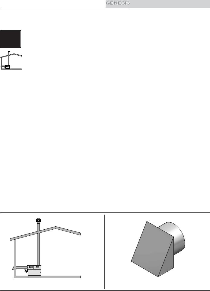
A |
Conventional negative draft venting - see page 15.
NOTICE |
Before installing a venting system, follow requirements found in the General Venting section. |
|
This option uses Type-B double-wall flue outlet piping. The blower brings in combustion air. The buoyancy of the heated flue products cause them to rise up through the flue pipe. The flue outlet terminates at the rooftop.
Negative draft
IMG00580 The negative draft in a conventional vent installation must be within the range of 0.02 to 0.08 inches w.c. to ensure proper operation. Make all draft readings while the unit is in stable operation (approximately 2 to 5 minutes).
Connect the flue vent directly to the flue outlet opening on the top of the unit. No additional draft diverter or barometric damper is needed on single unit installations with a dedicated stack and a negative draft within the specified range of 0.02 to 0.08 inches w.c. If the draft in a dedicated stack for a single unit installation exceeds the maximum specified draft, you must install a barometric damper to control draft. Multiple unit installations with combined venting or common venting with other Category I negative draft appliances require each water heater to have a barometric damper installed to regulate draft within the proper range.
Do not connect vent connectors serving appliances vented by natural draft (negative draft) to any portion of a mechanical draft system operating under positive pressure. Connecting to a positive pressure stack may cause flue products to be discharged into the living space causing serious health injury.
Flue outlet piping
With this venting option, you must use Type-B double-wall vent materials. Vent materials must be listed by a nationally-recognized test agency for use as vent materials. Make the connections from the unit vent to the outside stack as direct as possible with no reduction in diameter. Use the National Fuel Gas Code venting tables for doublewall vent to properly size all vent connectors and stacks. Follow the vent manufacturer’s instructions when installing Type-B vents and accessories, such as firestop spacers, vent connectors, thimbles, caps, etc.
Provide adequate clearance to combustibles for the vent connector and firestop.
When planning the venting system, avoid possible contact with plumbing or electrical wiring inside walls, ceilings, and floors. Locate the unit as close as possible to a chimney or gas vent.
Avoid long horizontal runs of the vent pipe, 90° elbows, reductions and restrictions.
No additional draft diverter or barometric damper is required on single unit installations with a dedicated stack and a negative draft maintained between 0.02 to 0.08 inches w.c.
Common Venting Systems
You can combine the flue with the vent from any other negative draft, Category I appliance. Using common venting for multiple negative draft appliances requires you to install a barometric damper with each unit. This will regulate draft within the proper range. You must size the common vent and connectors from multiple units per the venting tables for Type-B double-wall vents in the latest edition of the National Fuel Gas Code, ANSI Z223.1 and/or CAN/ CGA-B149 Installation Code.
Common venting systems may be too large when an existing unit is removed.
At the time of removal of an existing appliance, the following steps shall be followed with each appliance remaining connected to the common venting system placed in operation, while other appliances remaining connected to the common venting system are not in operation.
1.Seal any unused opening in the common venting system.
2.Visually inspect the venting system for proper size and horizontal pitch. Make sure there is no blockage or restriction, leakage, corrosion and other unsafe conditions.
3.If possible, close all building doors and windows. Close all doors between the space in which the appliances remaining connected to the common venting system are located and other building spaces.
 17
17 

Installation & Service Manual
2 Venting
4.Turn on clothes dryers and any other appliances not connected to the common venting system. Turn on any exhaust fans, such as range hoods and bathroom exhausts, so they will operate at maximum speed. Do not operate a summer exhaust fan.
5.Close fireplace dampers.
6.Place in operation the unit being inspected. Follow the lighting instructions. Adjust thermostat so unit will operate continuously.
7.Test for spillage at the draft hood/relief opening after 5 minutes of main burner operation. Use the flame of a match or candle, or smoke from a cigarette, cigar or pipe.
8.After making sure that each appliance remaining connected to the common venting system properly vents when tested as above, return doors, windows, exhaust fans, fireplace dampers and other gas burning appliances to their previous conditions of use.
9.Correct any improper operation of the common venting system so that the installation conforms to the latest edition of the National Fuel Gas Code, ANSI Z223.1, in Canada, the latest edition of CAN/CGA-B149 Installation Code for Gas Burning Appliances and Equipment. When resizing any portion of the common venting system, resize to approach the minimum size as determined using the appropriate tables of the latest edition of the National Fuel Gas Code, ANSI Z223.1, in Canada, the latest edition of CAN/CGA-B149 Installation Code for Gas Burning Appliances and Equipment.
Masonry chimney installations
A masonry chimney must be properly sized for the installation of a high efficiency gas-fired appliance. Venting of a high efficiency appliance into a cold or oversized masonry chimney can result in operational and safety problems. Exterior masonry chimneys, with one or more sides exposed to cold outdoor temperatures, are more likely to have venting problems. The temperature of the flue products from a high efficiency appliance may not be able to sufficiently heat the masonry structure of the chimney to generate proper draft. This will result in condensing of flue products, damage to the masonry flue/tile, insufficient draft and possible spillage of flue products into an occupied living space. Carefully inspect all chimney systems before installation.
WARNING |
Do not vent this unit into a masonry chimney without a sealed stainless steel liner system. Any breaks, leaks, |
|
|
or damage to the masonry flue/tile will allow the flue products to leak from the chimney and into occupied |
|
|
living spaces. This could cause serious injury or death due to carbon monoxide poisoning and other harmful |
|
|
flue products. |
|
|
Check with local code officials to determine code requirements or the advisability of using a masonry chimney |
|
NOTICE |
||
with a sealed corrosion-resistant liner system. |
||
Inspection of a masonry chimney |
||
A masonry chimney must be carefully inspected to determine its suitability for the venting of flue products. A clay-tile-lined chimney must be structurally sound, straight and free of misaligned tile, gaps between liner sections, missing sections of liner or any signs of condensate drainage at the breaching or clean out. If there is any doubt about the condition of a masonry chimney, it must be relined with a properly-sized and approved chimney liner system. An unlined masonry chimney must not be used to vent flue products from this high-efficiency unit. An unlined chimney must be relined with an approved chimney liner system when a new appliance is being attached to it. Metallic liner systems (Type-B double-wall or flexible or rigid metallic liners) are recommended. Consult with local code officials to determine code requirements or the advisability of using or relining a masonry chimney.
Vertical vent termination clearances and location
The vent terminal should be vertical and exhaust outside the building at least 2 feet (0.61m) above the highest point of the roof within a 10 foot (3.05m) radius of the termination.
The vertical termination must be a minimum of 3 feet (0.91m) above the point of exit.
A vertical termination less than 10 feet (3.05m) from a parapet wall must be a minimum of 2 feet (0.61m) higher than the parapet wall.
Keep the vent cap clear of snow, ice, leaves, and debris to avoid blocking the flue.
 18
18 

Installation & Service Manual
2 Venting (continued)
Figure 2-1_Vent Termination from Peaked Roof - 10 ft. or Less From Ridge
Figure 2-2_Vent Termination from Peaked Roof - 10 ft. or More From Ridge
NOTICE |
|
Vent terminations are not shown in FIG.’s 2-1 thru 2-4. Make sure all vertical vents are installed with vent |
|||||||||||||||||||||||||||||||||||||||||||||||||
|
terminations recommended by the vent manufacturer. |
||||||||||||||||||||||||||||||||||||||||||||||||||
|
|
|
|
|
|
|
|
|
|
|
|
||||||||||||||||||||||||||||||||||||||||
|
|
|
|
|
|
|
|
|
|
|
|
|
|
|
|
|
|
|
|
|
|
|
|
|
|
|
|
|
|
|
|
|
|
|
|
|
|
|
|
|
|
|
|
|
|
|
|
|
|
|
|
|
|
|
|
|
|
|
|
|
|
|
|
|
|
|
|
|
|
|
|
|
|
|
|
|
|
|
|
|
|
|
|
|
|
|
|
|
|
|
|
|
|
|
|
|
|
|
|
|
|
|
|
|
|
|
|
|
|
|
|
|
|
|
|
|
|
|
|
|
|
|
|
|
|
|
|
|
|
|
|
|
|
|
|
|
|
|
|
|
|
|
|
|
|
|
|
|
|
|
|
|
|
|
|
|
|
|
|
|
|
|
|
|
|
|
|
|
|
|
|
|
|
|
|
|
|
|
|
|
|
|
|
|
|
|
|
|
|
|
|
|
|
|
|
|
|
|
|
|
|
|
|
|
|
|
|
|
|
|
|
|
|
|
|
|
|
|
|
|
|
|
|
|
|
|
|
|
|
|
|
|
|
|
|
|
|
|
|
|
|
|
|
|
|
|
|
|
|
|
|
|
|
|
|
|
|
|
|
|
|
|
|
|
|
|
|
|
|
|
|
|
|
|
|
|
|
|
|
|
|
|
|
|
|
|
|
|
|
|
|
|
|
|
|
|
|
|
|
|
|
|
|
|
|
|
|
|
|
|
|
|
|
|
|
|
|
|
|
|
|
|
|
|
|
|
|
|
|
|
|
|
|
|
|
|
|
|
|
|
|
|
|
|
|
|
|
|
|
|
|
|
|
|
|
|
|
|
|
|
|
|
|
|
|
|
|
|
|
|
|
|
|
|
|
|
|
|
|
|
|
|
|
|
|
|
|
|
|
|
|
|
|
|
|
|
|
|
|
|
|
|
|
|
|
|
|
|
|
|
|
|
|
|
|
|
|
|
|
|
|
|
|
|
|
|
|
|
|
|
|
|
|
|
|
|
|
|
|
|
|
|
|
|
|
|
|
|
|
|
|
|
|
|
|
|
|
|
|
|
|
|
|
|
|
|
|
|
|
|
|
|
|
|
|
|
|
|
|
|
|
|
|
|
|
|
|
|
|
|
|
|
|
|
|
|
|
|
|
|
|
|
|
|
|
|
|
|
|
|
|
|
|
|
|
|
|
|
|
|
|
|
|
|
|
|
|
|
|
|
|
|
|
|
|
|
|
|
|
|
|
|
|
|
|
|
|
|
|
|
|
|
|
|
|
|
|
|
|
|
|
|
|
|
|
|
|
|
|
|
|
|
|
|
|
|
|
|
|
|
|
|
|
|
|
|
|
|
|
|
|
|
|
|
|
|
|
|
|
|
|
|
|
|
|
|
|
|
|
|
|
|
|
|
|
|
|
|
|
|
|
|
|
|
|
|
|
|
|
|
|
|
|
|
|
|
|
|
|
|
|
|
|
|
|
|
|
|
|
|
|
|
|
|
|
|
|
|
|
|
|
|
|
|
|
|
|
|
|
|
|
|
|
|
|
|
|
|
|
|
|
|
|
|
|
|
|
|
|
|
|
|
|
|
|
|
|
|
|
|
|
|
|
|
|
|
|
|
|
|
|
|
|
|
|
|
|
|
|
|
|
|
|
|
|
|
|
|
|
|
|
|
|
|
|
|
|
|
|
|
|
|
|
|
|
|
|
|
|
|
|
|
|
|
|
|
|
|
|
|
|
|
|
|
|
|
|
|
|
|
|
|
|
|
|
|
|
|
|
|
|
|
|
|
|
|
|
|
|
|
|
|
|
|
|
|
|
|
|
|
|
|
|
|
|
|
|
|
|
|
|
|
|
|
|
|
|
|
|
|
|
|
|
|
|
|
|
|
|
|
|
|
|
|
|
|
|
|
|
|
|
|
|
|
|
|
|
|
|
|
|
|
|
|
|
|
|
|
|
|
|
|
|
|
|
|
|
|
|
|
|
|
|
|
|
|
|
|
|
|
|
|
|
|
|
|
|
|
|
|
|
|
|
|
|
|
|
|
|
|
|
|
|
|
|
|
|
|
|
|
|
|
|
|
|
|
|
|
|
|
|
|
|
|
|
|
|
|
|
|
|
|
|
|
|
|
|
|
|
|
|
|
|
|
|
|
|
|
|
|
|
|
|
|
|
|
|
|
|
|
|
|
|
|
|
|
|
|
|
|
|
|
|
|
|
|
|
|
|
|
|
|
|
|
|
|
|
|
|
|
|
|
|
|
|
|
|
|
|
|
|
|
|
|
|
|
|
|
|
|
|
|
|
|
|
|
|
|
|
|
|
|
|
|
|
|
|
|
|
|
|
|
|
|
|
|
|
|
|
|
|
|
|
|
|
|
|
|
|
|
|
|
|
|
|
|
|
|
|
|
|
|
|
|
|
|
|
|
|
|
|
|
|
|
|
|
|
|
|
|
|
|
|
|
|
|
|
|
|
|
|
|
|
|
|
|
|
|
|
|
|
|
|
|
|
|
|
|
|
|
|
|
|
|
|
|
|
|
|
|
|
|
|
|
|
|
|
|
|
|
|
|
|
|
|
|
|
|
|
|
|
|
|
|
|
|
|
|
|
|
|
|
|
|
|
|
|
|
|
|
|
|
|
|
|
|
|
|
|
|
|
|
|
|
|
|
|
|
|
|
|
|
|
|
|
|
|
|
|
|
|
|
|
|
|
Figure 2-3_Vent Termination from Flat Roof - 10 ft. or Less From Parapet Wall
Figure 2-4_Vent Termination from Flat Roof - 10 ft. or More From Parapet Wall
 19
19 
Installation & Service Manual
2 Venting
Vertical Vent/Ducted Air - see page 15.
B |
NOTICE |
Before installing a venting system, follow requirements found in the General Venting section. |
|
The Vertical Vent/Ducted Air vent system is the same as the Conventional Negative Draft vent system, except it pulls combustion air from the outdoors through a separate air inlet pipe. Follow all requirements in the Conventional Negative Draft Venting section on page 17.
The Vertical Vent/Ducted Air vent system requires you to install two pipes directly to the unit; one vertical pipe IMG00583 with a rooftop termination for the flue products and one pipe for combustion air. For this venting option, you must purchase the DV box adapter from the appliance manufacturer. The DV box attaches to the air inlet of the unit. The pipe for combustion air attaches to the DV box (see FIG. 2-10 on page 29). Reference page 29 for a list of approved
air intake materials.
Combustion air inlet piping
WARNING |
Locate and install the combustion air inlet cap correctly. Failure to do so can allow the discharge of flue products |
|
to be drawn into the combustion process. This can result in incomplete combustion and potentially hazardous |
|
levels of carbon monoxide in the flue products. This will cause operational problems and the spillage of flue |
|
products. Spillage of flue products can cause personal injury or death due to carbon monoxide poisoning. |
The sidewall or vertical rooftop Vent/Ducted Air combustion air supply system has specific material and installation requirements. The air inlet pipe connects directly to the unit to supply combustion air. In most installations, the combustion air inlet pipe will be a dedicated system with one air inlet pipe per unit. You can combine multiple air inlets if the guidelines in Combined Air Inlet Points, page 21 are followed. The air inlet pipe will be connected to a combustion air inlet cap as specified in this section.
For normal installations, this system uses a single-wall pipe to supply combustion air from outdoors directly to the unit.
In cold climates, use a Type-B double-wall vent pipe or an insulated single-wall pipe for combustion air. This will help prevent moisture in the cool incoming air from condensing and leaking from the inlet pipe.
Length of air inlet pipe
The installed length of air inlet pipe from the unit to the outside air inlet cap must not exceed 50 equivalent feet (15.2m). Subtract 5 feet (1.5m) of equivalent length for each 90° elbow. Subtract 2.5 feet (0.7m) of equivalent length for each 45° elbow.
Do not exceed the limits for the combustion air inlet piping lengths.
Sidewall air inlet
The sidewall air inlet cap is supplied in the Sidewall Air Inlet Kit. Order the kit from the appliance manufacturer. This sidewall cap supplies combustion air for a single unit only. See Table 2B, page 22, for kit numbers.
Locate the unit as close as possible to the sidewall where you will install the combustion air supply system.
IMG00583 |
|
Figure 2-5_Sidewall Combustion Air Inlet |
Figure 2-6_Air Inlet Cap for Sidewall Termination |
 20
20 
Installation & Service Manual
2 Venting (continued)
To prevent recirculation of flue products from an adjacent vent cap into the combustion air inlet, follow all applicable clearance requirements in the latest edition of the National Fuel Gas Code and/or CAN/CGA-B149 Installation Code and instructions in the Installation and Operation Manual.
Clearances
You must install the combustion air inlet cap at least one foot (0.30m) above ground level and above normal snow levels.
The point of termination for the combustion air inlet cap must be at least 3 feet (0.91m) below the point of flue gas termination if it is located within 10 feet (3.05m) of the flue outlet. Make sure to properly install the air inlet cap assembly on the air inlet pipe.
Do not install the combustion air inlet cap closer than 10 feet (3.05m) from an inside corner of an L-shaped structure.
Vertical Rooftop Air Inlet
Use the vertical air inlet terminations available from the appliance manufacturer, recommended and/or supplied by the vent manufacturer, or use two 90° elbows as described on page 30.
3' |
MIN |
12" MIN
You must locate the air inlet termination elbow at least 12" (30cm) above the roof or above normal snow levels.
If the air inlet cap is within a 10-foot (3.05m) radius of the flue outlet, the point of termination for the combustion air inlet cap must be at least 3 feet (0.91m) below the point of flue gas termination (vent cap).
Do not install the combustion air inlet cap closer than 10 feet (3.05m) from an inside corner of an L-shaped structure.
|
Combined air inlet points |
|
The air inlet pipes from multiple units can be combined to a |
|
single common connection if the common air inlet pipe has a |
|
cross sectional area equal to or larger than the total area of all air |
|
inlet pipes connected to the common air inlet pipe. |
IMG00586 |
Example: Two 10" air inlet pipes (78.5 in2 area each) have a total |
Figure 2-7_Rooftop Combustion Air Inlet |
area of 157 in2 and will require a 15" (176.7 in2 area) common |
|
air inlet pipe. |
The air inlet point for multiple unit air inlets must be provided with an exterior opening which has a free area equal to or greater than the total area of all air inlet pipes connected to the common air inlet. This exterior opening for combustion air must connect directly to the outdoors. The total length of the combined air inlet pipe must not exceed a maximum of 50 (15.2m) equivalent feet.
Subtract 5 feet (1.5m) for each 90° elbow in the air inlet pipe. You must deduct the restriction in area provided by any screens, grills or louvers installed in the common air inlet point. These are common on the sidewall air inlet openings. Screens, grills or louvers installed in the common air inlet can reduce the free area of the opening from 25% to 75% based on the materials used.
You can terminate the combustion air pipe either horizontally with a sidewall air inlet or vertically with a rooftop air inlet. The installed length of air inlet pipe from the unit to the outside air inlet cap must not exceed 50 equivalent feet (15.2m).
 21
21 
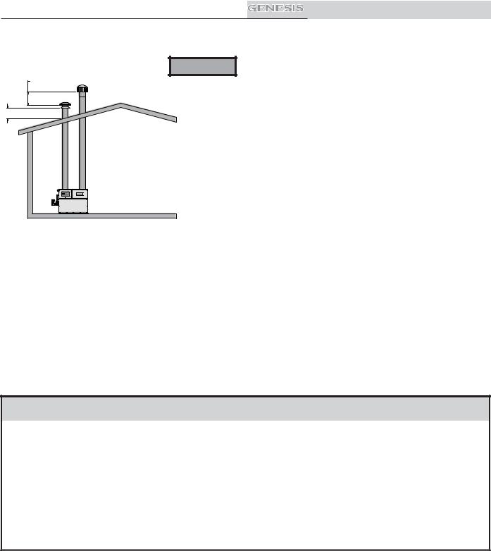
Installation & Service Manual
2 Venting
3' |
MIN |
12" MIN
WARNING Only use a sidewall air inlet cap supplied by the appliance manufacturer or a rooftop air inlet cap supplied by either the vent
or appliance manufacturer. Using any other air inlet cap for single unit installations or using a common air inlet cap for multiple units with insufficient free area and/or protections from wind and weather may result in operational problems and the spillage of flue products. Spillage of flue products can cause personal injury or death due to carbon monoxide poisoning.
For single unit installations with sidewall air inlet you must order the sidewall air inlet kit from the appliance manufacturer. The part number for each SVK kit is listed by unit size in Table 2B.
For single unit installations with rooftop air inlet (see FIG. 2-8), you must order the rooftop air inlet kit from the appliance manufacturer. The part number for IMG00586 each VDK kit is listed by unit size in Table 2B. Purchase the flue pipe, rooftop
flue termination, and air inlet pipe locally.
Figure 2-8_Vertical Vent/Ducted Air Installation w/Rooftop Combustion Air Inlet
There is no vent kit for combined air supply systems for multiple units. Make sure the air inlet cap is properly sized. You must purchase this cap locally.
Venting of flue products
For venting flue products vertically to the outdoors, follow all requirements in the installation instructions for conventional venting in this manual.
Follow all clearance requirements in Vertical Vent Termination Clearances and Location on page 18.
A barometric damper is not required in the flue on Vertical Vent/Air installations if the draft is within the negative 0.02 to 0.08 inches w.c. required for proper operation. If the draft exceeds this range, install a barometric damper.
TABLE - 2B
VERTICAL VENT/AIR KITS
MODEL |
HORIZONTAL KIT* |
VERTICAL KIT* |
400 |
9910113000 |
9910111000 |
500 |
9910113000 |
9910111000 |
650 |
9910113001 |
9910111001 |
750 |
9910113001 |
9910111001 |
1000 |
9910113002 |
9910111002 |
1250 |
9910113003 |
9910111003 |
1450 |
9910113003 |
9910111003 |
1800 |
9910113003 |
9910111003 |
2100 |
9910113003 |
9910111003 |
*The SVK kits include a DV box adapter and sidewall air inlet cap. The VDK kits include a DV box adapter and a rooftop air inlet cap.
 22
22 
Installation & Service Manual
2 Venting (continued)
Sidewall venting - see page 15.
C |
NOTICE |
Before installing a venting system, follow all requirements found in the General Venting |
section. |
This option uses a powered vent assembly which pulls the flue products out of the stack. This fan generates a negative draft at the unit. Combustion air is drawn from the equipment room (see Combustion and Ventilation Air on 10).
Sidewall with fan
The sidewall fan can be mounted on the inside/outside (depending upon model) with a sidewall vent hood installed on the exterior wall. The sidewall fan and accessories are included in a venting kit provided by the appliance manufacturer. See Table 2C on page 25 for kit numbers.
The venting kit includes the sidewall fan, vent hood, tapered vent adapter, barometric damper (1000 - 2100 Models), proving switch and all necessary relays to interlock with the heaters control system. The tapered vent adapter reduces the vent size at the inlet to the fan. There should be no reduction in vent diameter from the unit’s flue outlet to the sidewall fan. The barometric damper must be installed on the flue and adjusted to supply a negative draft within the range of 0.04 to 0.08 inches w.c. while unit is operating.
Flue outlet piping
With this venting option, you must use Type-B double-wall (or equivalent) vent materials. Vent materials must be listed by a nationally-recognized test agency for use as vent materials. Make the connections from the unit vent to the sidewall fan/cap as direct as possible with no reduction in diameter. Use the National Fuel Gas Code venting tables for double-wall vent to properly size all vent connectors and stacks. Follow the vent manufacturer’s instructions when installing Type-B vents and accessories, such as firestop spacers, vent connectors, thimbles, caps, etc.
When planning the venting system, avoid possible contact with plumbing or electrical wiring inside walls.
The maximum installed length of sidewall vent pipe with an induced draft fan must not exceed 100 feet (30.5m). Subtract 5 feet (1.5m) for each 90° elbow. Subtract 2.5 feet (0.7m) for each 45° elbow.
Sidewall venting termination
The sidewall vent cap must be installed on an exterior sidewall. The sidewall fan/powered sidewall vent cap and accessories are included in a venting kit which is furnished by the appliance manufacturer in accordance with CSA International requirements. This venting kit includes the powered sidewall fan/cap, proving switch and all necessary relays to interlock with the heaters control system.
The sidewall fan/powered vent cap must be interlocked with the units control system to start the fan on a call for heat and prove fan operation before the water heater fires. Plug-in and terminal strip connections are provided on the unit for easy connection of the factory supplied vent kit and control package for the sidewall vent fan. See the installation instructions provided with the vent kit.
Sidewall vent termination clearances and location
Locate the bottom of the vent terminal at least 12 inches (30cm) above grade and above normal snow levels. Locate the bottom of the vent terminal at least 7 feet (2.13m) above grade when located adjacent to public walkways. Do not terminate directly above a public walkway.
Do not terminate the venting system in a window well, stairwell, alcove, courtyard, or other recessed area. Do not terminate the venting system below grade.
Locate vent termination at least 3 feet (0.91m) from an inside corner of an L-shaped structure.
Provide a minimum clearance of 4 feet (1.2m) horizontally from electric meters, gas meters, regulators, and relief equipment. Never locate vent cap above or below electric meters, gas meters, regulators, and relief equipment unless a 4 foot (1.2m) horizontal clearance is maintained.
 23
23 
 Loading...