


A.O. Smith – Voltex™
Hybrid Electric
Heat Pump Water Heater
Installation
Instructions and
Use & Care Guide
To obtain technical, warranty or service assistance during or after
the installation of this water heater, call toll free
1-800-527-1953
When calling for assistance, please have the following information ready:
1.Model number
2.7 Digit product number
3.Serial number
4.Date of installation
5.Place of Purchase
Table of Contents |
Page |
Water Heater Safety ................................................................................ |
2 |
Installing Your Water Heater ................................................................. |
3-9 |
Consumer Information ................................................................. |
3 |
Consumer Responsibilities .......................................................... |
3 |
Unpacking Instructions ............................................................. |
3-4 |
Location Requirements ............................................................... |
4 |
Confined Space Installation....................................................... |
5-6 |
Water System Piping................................................................. |
7-8 |
Temperature & Pressure Relief Valve..................................... |
9-10 |
Electrical Requirements ....................................................... |
10-11 |
Installation Checklist .............................................................................. |
12 |
Operating Your Water Heater ............................................................ |
13-15 |
Before Using ............................................................................. |
13 |
Water Temperature Regulation ................................................. |
13 |
Adjusting the User Interface Module/ Operational Mode .......... |
14 |
Operational Conditions .............................................................. |
15 |
Maintenance of Your Water Heater ................................................... |
16-17 |
Temperature and Pressure Relief Valve..................................... |
16 |
Draining and Flushing................................................................ |
16 |
Heating Element Replacement............................................. |
16-17 |
Cleaning the Heat Pump............................................................ |
17 |
Diagnostic Codes ................................................................................... |
18 |
Troubleshooting Chart ............................................................................ |
19 |
Repair Parts Illustration .......................................................................... |
20 |
Notes... .............................................................................................. |
21-22 |
318257-002 April, 2012
1
WATER HEATER SAFETY
Your safety and the safety of others are very important.
We have provided many important safety messages in this manual and on your appliance. Always read and obey all safety messages.
This is the safety alert symbol.
This symbol alerts you to potential hazards that can kill or hurt you and others.
All safety messages will follow the safety alert symbol and either the word “DANGER” or “WARNING.” These words mean:
You can be killed or seriously injured if you don’t immediately follow instructions.
You can be killed or seriously injured if you don’t follow instructions.
All safety messages will tell you what the potential hazard is, tell you how to reduce the chance of injury, and tell you what can happen if the instructions are not followed.
Important Safety Instructions
CAUTION: Hydrogen gas is produced in a hot water system served by this heater that has not been used for a long period of time (2 weeks or more). Hydrogen gas is extremely flammable. To reduce the risk of injury under these conditions, it is recommended that the hot water faucet be opened for several minutes at the kitchen sink before using any electrical appliance connected to the hot water system. When hydrogen is present, there will probably be an unusual sound such as air escaping through the pipe as the water begins to flow. There should be no smoking or open flame near the faucet at the time it is open.
The California Safe Drinking Water and Toxic Enforcement Act requires the Governor of California to publish a list of substances known to the State of California to cause cancer, birth defects, or other reproductive harm, and requires businesses to warn of potential exposure to such substances.
WARNING: This product contains a chemical known to the State of California to cause cancer, birth defects, or other reproductive harm.
This appliance can cause low-level exposure to some of the substances included in the Act.
IMPORTANT: The heat pump portion of this water heater uses R-134a refrigerant. See the data plate on the heat pump jacket for the charge level.
2
INSTALLING YOUR WATER HEATER
Consumer Information
This water heater should be installed in accordance with the local code authority having jurisdiction, the power company or electric utility, and this installation manual. In the absence of local code requirements, follow the regulations set forth in the latest edition of The National Electric Code, NFPA 70. This is available from the following:
National Fire Protection Association 1 Batterymarch Park
Quincy, MA 02269
American National Standards Institute 1430 Broadway
New York, NY 10018
Check your phone listings for the local authorities having jurisdiction over your installation.
the water while the electric elements only function during high demand periods. (See “Adjusting the User Interface Module/ Operational Mode” section). The more often the unit operates using the heat pump, rather than the elements, the more efficient the unit will be.
The tank capacity of this heat pump water heater is sized to maximize the use of the heat pump to deliver hot water at a lower cost as compared to heat pump waters with lower tank capacities (50 gallons or less.)
The HPWH uses about half the electricity of a comparably sized conventional electric water heater when operating in the Efficiency Mode, and provides up to ½ ton cooling capacity and dehumidification. It is designed for indoor, residential applications for installation in a basement, garage or utility room (See “Location Requirements” section).
Consumer Responsibilities
This manual has been prepared to acquaint you with the installation, operation and maintenance of your electric heat pump water heater and to provide important safety information in these areas.
We urge you to read all of the instructions thoroughly before attempting the installation or operation of this water heater. This manual should be kept for future reference.
The manufacturer of this water heater will not be liable for any damages caused by failure to comply with the installation and operating instructions outlined in this manual.
If you lack the necessary skills required to properly install this water heater or you have difficulty following the directions, you should not proceed but have a qualified person perform the installation of this water heater.
Examples of a qualified person include: licensed plumbers, authorized electric company personnel, and authorized service personnel.
Massachusetts code requires this water heater to be installed in accordance with Massachusetts 248-CMR 2.00: State Plumbing Code and 248-CMR 5.00.
A data plate identifying your water heater can be found adjacent to the upper element door. When referring to your water heater always have the information listed on the data plate readily available, to include the model and serial number.
Retain your original receipt as proof of purchase.
Basic Operation Fundamentals
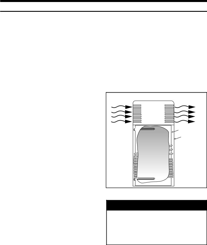
The Heat Pump Water Heater (HPWH) is an integrated heat pump water heater unit, having an 850 watt compressor and external coil heat exchanger with backup electric elements (See Figure 1). When in Efficiency Mode the heat pump draws heat from the ambient air in the room and transfers it to the water in the tank through the coil heat exchanger. While in Electric Mode the water heater functions like a standard electric water heater, relying on the electric elements to heat the water. A Hybrid Mode is available that relies primarily on the heat pump to heat
Figure 1
Heat Pump Water Heater Basic Operation
Ambient Air |
Cool/Dehumidified Air |
Heat Pump (Transfers heat from ambient air to Heat Exchanger)
Upper Element |
Water Tank |
(4500 Watt) |
|
|
Jacket |
|
Heat Exchanger |
|
(Heat Transfer Coils) |
Lower Element |
|
(2000 Watt) |
|
Unpacking the Water Heater
 WARNING
Excessive Weight Hazard
Use two or more people to move and install water heater.
Failure to do so can result in back or other injury.
Removing Packaging Materials
IMPORTANT: Do not remove, cover or deface any permanent instructions, labels, or the data label from either the outside of the water heater or on the inside of water heater panels.
3
•The water heater must NOT be placed on its side. It should be transported and stored in an upright position.
•Remove exterior packaging and place installation components aside.
•Inspect all parts for damage prior to installation and start-up.
•Completely read all instructions before attempting to assemble and install this product.
•After installation, dispose of/recycle all packaging materials.
Location Requirements
Site location
Select a location near the center of the water piping system. The unit must be installed indoors and in a vertical position on a level surface. The flooring beneath the water heater must be able to support the weight of the water heater when filled with water (See Table 1).
IMPORTANT: The water heater must have unresticted airflow and requires a minimum installation space of 750 cubic feet. As an example, a room that has an eight foot tall ceiling and is 10 feet long by 9-1/2 feet wide would contain
760 cubic feet. See The Confined Space Installation section of this manual for installing the water heater in spaces of less than 750 cubic feet.
NOTE: To ensure optimal performance and efficiency a minimum clearance of six (6) inches from the back, left and right sides of the water heater must be maintained. A minimum of 12 inches from the front of the unit should be maintained for control access. Service clearances of three
(3) feet from the left and right sides are recommended as a best installation practice.
The water heater should be located in an area not subject to freezing temperatures. Water heaters located in unconditioned spaces (i.e., garages, basements, etc.) may require the water piping, condensate piping, and drain piping to be insulated to shelter against freezing. The drain and controls must be easily accessible for operation and service.
The site location must be free from any corrosive elements in the atmosphere such as sulfur, fluorine, and chlorine.
These elements are found in aerosol sprays, detergents, bleaches, cleaning solvents, air fresheners, paint, and varnish removers, refrigerants, and many other commercial and household products. In addition, excessive dust and lint may affect the operation of the unit (See “Cleaning the Filter” section).
The ambient air temperature must also be considered when installing this unit. In Efficiency Mode the ambient air temperature must be above 45°F and below 109°F. If the ambient air temperature falls outside these upper and lower limits the electrical elements will activate to meet the hot water demand and the heat pump does not operate.
NOTE: Local codes and requirements in your area may require the installation of your water heater be accomplished in a way that the bottom element is elevated from the
floor at least 18 inches. Ensure that a platform capable of supporting the combined weight of the water heater and water is used.
Table 1
Capacity |
Weight (lbs) |
60 Gallon |
760 |
80 Gallon |
967 |
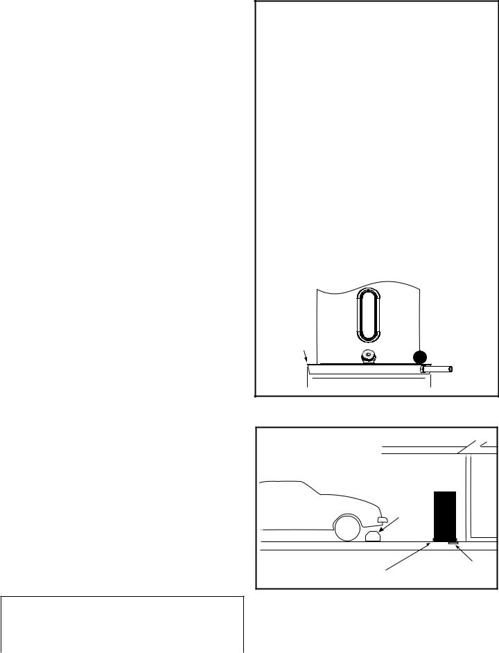
IMPORTANT: The water heater should be located in an area where leakage of the tank, connections, condensate lines or condensate will not result in damage to the area adjacent to the water heater or to lower floors of the structure. Due to the normal corrosive action of the water, the tank will eventually leak after an extended period of time. Also, any external plumbing leak, including those from improper installation, may cause early failure of the tank due to corrosion if not repaired. If the homeowner is uncomfortable with making the repair a qualified person should be contacted. A suitable metal drain pan should be installed under the water heater as shown below, to help protect the property from damage which may occur from condensate formation or leaks in the piping connections or tank. The pan must limit the water level to a maximum depth of 2-1/2 inches and be two inches wider than the heater and piped to an adequate drain. Locate the water heater near a suitable indoor drain. Outside drains are subject to freezing temperatures which can obstruct the drain line. The piping should be at least 3/4” ID and sloped for proper drainage. Under no circumstance will the manufacturer or seller of this water heater be held liable for any water damage which is caused by your failure to follow these instructions.
Figure 2
Metal Drain Pan
Installation
METAL
DRAIN
PAN
 PIPED TO AN
ADEQUATE DRAIN
 AT LEAST 2” GREATER THAN THE
DIAMETER OF THE WATER HEATER.
NOTE: The water heater shall be located so it is not subject to physical damage by moving vehicles or area flooding.
Figure 3 |
|
Residential Garage |
|
Installation |
|
|
Vehicle |
|
Stop |
Drain |
Drain |
Pan |
|
State of California
NOTE: The water heater must be braced, anchored, or strapped to avoid moving during an earthquake. Contact local utilities for code requirements in your area, visit http://www.dsa.dgs.ca.gov, or call 1-916-445-8100 and request instructions.
4

Confined Space Installation
The heat pump water heaters covered in this manual require a minimum of 750 cubic feet of installation space. When a space meeting this minimum requirement is not available these units may be installed in spaces with less than 750 cubic feet (confined spaces) when provisions are made by installing an accessory Outlet Duct Kit and/or louvered grills as described in this section.
Inlet air will be derived from an alternate location inside the building structure through one or more louvered grills or through a fully louvered door leading into the confined space. The alternate location from where inlet air will be derived must provide a minimum of
750 cubic feet of space when using this installation method. When the Outlet Duct Kit is installed outlet air from the unit is redirected to an alternate location. The alternate location to where outlet air will be redirected must also provide a minimum of 750 cubic feet of space.
Other configurations are possible when using the Outlet Duct Kit (PN 9910006000) and/or the Inlet Duct Kit (PN 9910005000) with these water heaters. Consult the installation instructions included with the duct kits for additional information. These instructions are also available on the manufacturer’s web site. Contact the distributor where the water heater was purchased for information on ordering these duct kits.
AIR FLOW |
|
|
EXTEND DUCT |
|
|
|
ABOVE INSULATION |
||
|
|
|
IN ATTIC SPACES |
|
|
BOOT/COLLAR |
|
||
CONFINED |
|
|
|
8 INCH |
|
|
|
||
SPACE |
|
|
|
|
|
|
|
FLEXIBLE |
|
AIR FLOW |
|
|
|
DUCT |
BOOT/COLLAR
LOUVERED |
OUTLET DUCT |
|
KIT ADAPTER |
||
GRILLS |
||
|
||
MINIMUM |
|
|
16” X 24” |
|
DUCT
TERMINATION
OR GRILL
AIR FLOW
AIR FLOW
FIGURE 4
5
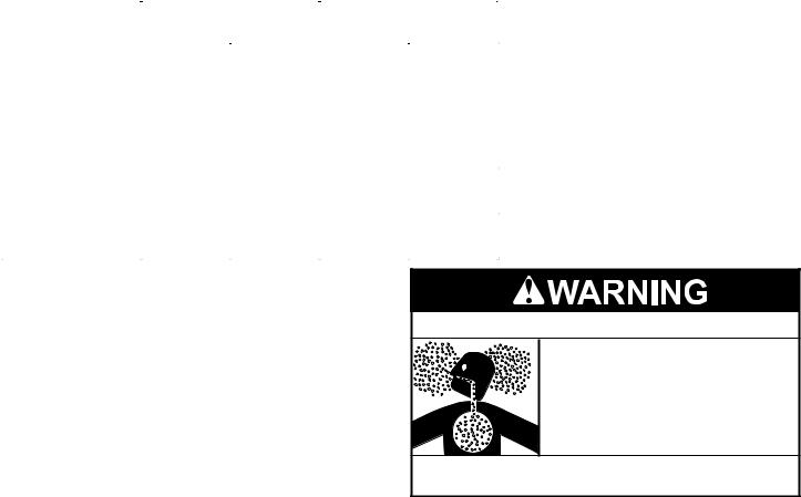
Table 2
ITEM |
|
WITHOUT DUCTWORK |
WITH 8 INCH FLEXIBLE DUCT |
|||||||||
|
|
AND OUTLET DUCT KIT |
||||||||||
|
|
|
|
|
|
|
|
|||||
|
|
|
|
|
|
|
|
|
|
|
|
|
LOUVERED GRILL |
|
|
|
|
|
|
|
|
|
|
|
|
|
|
|
|
|
|
|
|
|
|
|
|
|
|
|
|
|
|
|
|
|
|
|
|
|
|
|
|
|
|
|
|
|
|
|
|
|
|
|
|
|
|
|
|
|
|
|
|
|
|
|
|
|
|
|
|
|
|
|
|
|
|
|
|
|
|
|
|
|
|
|
|
|
|
|
|
|
|
|
|
|
|
|
|
|
|
|
|
|
|
|
CONFINED SPACE |
|
|
|
|
|
|
|
|
|
|
|
|
CONFIGURATION |
|
|
|
|
|
|
|
|
|
|
|
|
(door or wall) |
|
|
|
|
|
|
|
|
|
|
|
|
|
|
|
|
|
|
|
|
|
|
|
|
|
|
|
|
|
|
|
|
|
|
|
|
|
|
MINIMUM SPACE |
610 |
|
460 |
|
400 |
|
128 |
|
||||
(cubic feet) |
|
|
|
|
||||||||
|
|
|
|
|
|
|
|
|
|
|
|
|
|
|
|
|
|
|
|
|
|
|
|
|
|
EXAMPLE ROOM SIZE |
8' x 7.6' x 10' |
8' x 5.75' x 10' |
8' x 10' x 5' |
|
8' x 4' x 4' |
|||||||
H X L X W (feet) |
|
|||||||||||
|
|
|
|
|
|
|
|
|
|
|
|
|
|
|
|
|
|
|
|
|
|
|
|
|
|
Installation
Installation requires ability equivalent to that of a qualified HVAC installer. Installation skills such as air supply, venting, and duct installation are required. If you are not qualified and licensed or certified as required by the authority having jurisdiction to perform a given task do not attempt installation. Contact a local HVAC contractor to perform the installation.
Installation must comply with all national, state and local building codes and agencies having jurisdiction. Check with your local building code authority if you have any questions regarding code compliance.
1.Inlet air is derived through louvered grill(s) installed in a door or wall between the installation space and another space inside the building structure. The space from where inlet air is derived must be a minimum of 750 cubic feet. See Figure 4.
2.Installation is permitted in confined spaces between 750 and 610 cubic feet of space using one louvered grill or in spaces between 610 and 460 cubic feet using two louvered grills. See
Figure 4 and Table 2.
3.Forinstallationinconfinedspacesoflessthan460cubicfeetthe accessory Outlet Duct Kit (PN 9910006000) is required. With this kit installation is permitted in confined spaces between 460 and 400 cubic feet with one louvered grill or in spaces between 400 and 128 cubic feet with two louvered grills. See Figure 4 and Table 2.
4.Minimum louvered grill size is 16” x 24” for each grill installed.
Fully louvered doors are an acceptable substitute for louvered grill(s) if the louvered area of the door is not less than the total required area the grill(s) would provide.
5.Follow the instructions included with the Outlet Duct Kit for the included duct adapter and ductwork.
6.Eight (8) inch flexible ducting is required but not supplied in the
Outlet Duct Kit. Suitable ducting is readily available at home centers or HVAC supplies.
7.Duct collars and boots may also be required but are not supplied with the Outlet Duct Kit. Suitable collars and boots are readily available from home centers or HVAC supplies.
8.The maximum length of duct allowed is 10 feet. This maximum length must not be exceeded under any circumstances.
9.Ducting should be installed as straightly as possible; there must be no kinks or flattening of the ductwork.
10.The Outlet Duct Kit and connected ductwork must redirect outlet air from the unit to a location other than the confined installation space. The alternate location to where the outlet air is redirected must be a minimum of 750 cubic feet.
Breathing Hazard - Carbon Monoxide Gas
 Do not duct air from a garage or other space where potentially harmful fumes from solvents, chemicals or exhaust from automobiles are present into any other space in the building structure.
 Gas and carbon monoxide detectors are available.
Breathing carbon monoxide can cause brain damage or death. Always read and understand instruction manual.
11.The outlet air from a unit installed in a garage or drawing inlet air from a garage or any area where solvents or other chemicals that emit potentially harmful fumes are stored or automobiles are located must never be ducted to any other space inside the building structure. This would include all occupied and unoccupied spaces such as attics or basements. Potentially harmful fumes and vapors could be introduced into living spaces.
12.A duct termination or grill is required at the end of the duct run but not supplied with the Outlet Duct Kit. Suitable duct terminations and grills are readily available from home centers or HVAC supplies. Terminations must be fitted with screens or designed to prevent rodents, other pests and debris from entering the ductwork. If terminated outdoors or to another space where water or moisture may enter the ductwork, terminations designed to prevent water or moisture infiltration must be used.
13.If outlet ductwork is terminated through a ceiling into an attic space provision must be made to ensure the ductwork terminates well above the insulation line in the attic to prevent insulation from entering the ductwork. A short section of 8 inch round metal duct may be used with a suitable duct termination.
Overall duct length, including flexible and metal duct must not exceed 10 feet.
14.Ductwork that transitions through walls or ceilings must be properly sealed to prevent rodent, other pests or moisture infiltration.
6
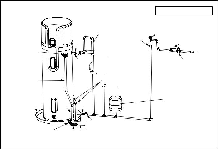
Water System Piping
Piping, fittings, and valves should be installed according to the installation drawing (Figure 5). If the indoor installation area is subject to freezing temperatures, the water piping must be properly insulated.
Water supply pressure should be 50-60 PSIG and not exceed the maximum 80 PSIG. If the supply line pressure exceeds 80 PSIG, a pressure reducing valve (PRV) with a bypass should be installed in the cold water supply line. This should be placed on the supply to the entire house in order to maintain equal hot and cold water pressures.
IMPORTANT:
•Heat must not be applied to the water fittings on the heater as they may contain nonmetallic parts. If solder connections are used, solder the pipe to the adapter before attaching the adapter to the hot and cold water fittings.
•Always use a good grade of joint compound and be certain that all fittings are tight.
IMPORTANT: DO NOT over apply joint compound.
Piping Installation
1.Install the water piping and fittings as shown in Figure 4. Connect the cold water supply (3/4” NPT) to the fitting marked “Cold”. Connect the hot water supply (3/4” NPT) to the fitting marked “Hot”.
2.The installation of unions in both the hot and cold water supply lines are recommended for ease of removing the water heater for service or replacement.
3.Some local codes may require, and the manufacturer of this water heater recommends, installing a mixing valve or an anti-scald device in the domestic hot water line as shown in Figure 5. These valves reduce the point-of-use temperature of the hot water by mixing cold and hot water and are readily available. Contact a licensed plumber or the local plumbing authority for more information.
4.Some local codes may require, and the manufacturer of this water heater recommends, installing a pressure reducing valve (PRV) in the cold water inlet line where it enters the residence as shown in Figure 5.
5.If installing the water heater in a closed water system, install an expansion tank in the cold water line as specified under “Closed System/Thermal Expansion.”
6.Install a shut off valve in the cold water inlet line. It should be located close to the water heater and be easily accessible. Know the location of this valve and how to shut off the water to the heater.
7.Install a discharge line from the temperature and pressure relief valve in the opening marked “T & P RELIEF VALVE”. See Figure 5 and the “Temperature and Pressure Relief Valve” section.)
8.After piping has been properly connected to the water heater, open the nearest hot water faucet. Then open the cold water shut off valve and allow the tank to completely fill with water. To purge the lines of any excess air and sediment, keep the hot water faucet open for 3 minutes after a constant flow of water is obtained. Close the faucet and check all connections for leaks.
Massachusetts: Install a vacuum relief in cold water line per section 19 MGL 142.
Temperature and
Pressure Relief Valve
Discharge Pipe
(Do Not Cap or Plug)
Metal Drain Pan 2 1/2” Depth Maximum and 2 Inches wider than the water heater. 
Cold (Inlet)
Optional Heat Trap Piping
Union
Union
Shut-off Valve (Hot)


 Untempered Water Outlet
Hot
(Outlet) Mixing Valve - Follow the Mixing Valve’s Manufacturer’s Installation Instructions.
(Set to 120° F)


 Tempered Water to Fixtures Condensate Drain Lines*


 Cold Water Outlet
Union
|
|
Shut-off Valve |
|
|
|
(Cold) |
|
Drain Line 3/4” |
Drain |
6” Maximum |
|
ID Minimum |
Air Gap |
||
|
Vacuum Relief Valve
 (when required by local code)
Cold Water
Inlet Valve
Cold Water
Inlet
Pressure Reducing Valve (PRV) should be installed where the water supply enters the residence.
When installed PRVs create a closed water system, a thermal expansion tank must be installed.
In a closed system, use a thermal expansion tank. See “Closed System/ Thermal Expansion” section.
* If an adequate drain is not available for the condensate drain lines then a condensate pump must be used. DO NOT discharge the condensate drain lines into the metal drain pan.
7
 Loading...