


 Loading...
Instruction Manual
RESIDENTIAL GAS WATER HEATERS
Ashland City, TN 37015 |
www.hotwater.com |
POWER VENT/POWER DIRECT VENT GAS MODELS WITH DIRECT SPARK IGNITION MODELS GDHE-50/GDHE-75 SERIES 130/131
• For Your Safety •
AN ODORANT IS ADDED TO THE GAS USED
Thank you for buying this energy efficient water heater. BY THIS WATER HEATER. We appreciate your confidence in our products.
ALL TECHNICAL AND WARRANTY QUESTIONS: SHOULD BE DIRECTED TO THE LOCAL DEALER FROM WHOM THE WATER HEATER WAS
PURCHASED. IF YOU ARE UNSUCCESSFUL, CALL THE TECHNICAL SUPPORT PHONE NUMBER SHOWN ON THE WATER HEATER LABELING.
|
KEEP THIS MANUAL IN THE POCKET ON HEATER FOR FUTURE REFERENCE |
|
|
WHENEVER MAINTENANCE ADJUSTMENT OR SERVICE IS REQUIRED. |
|
PRINTED 0115 |
1 |
326459-001 |
|
|

TABLE OF CONTENTS
SAFE INSTALLATION, USE AND SERVICE................................. |
3 |
APPROVALS.................................................................................. |
3 |
GENERAL SAFETY INFORMATION............................................. |
4 |
Precautions............................................................................... |
4 |
Grounding Instructions.............................................................. |
4 |
Hydrogen Gas Flammable........................................................ |
4 |
INTRODUCTION............................................................................ |
7 |
Abbreviations Used................................................................... |
7 |
Qualifications............................................................................ |
7 |
iCOMM™ & BACnet Compatible.............................................. |
7 |
Preparing For The Installation................................................... |
7 |
DIMENSIONS AND CAPACITY DATA........................................... |
8 |
Rough In Dimensions: 50 Gallon Unit....................................... |
8 |
Rough In Dimensions: 75 Gallon Unit....................................... |
8 |
FEATURES AND COMPONENTS............................................... |
10 |
Controls And Switches............................................................ |
13 |
INSTALLATION CONSIDERATIONS........................................... |
14 |
Locating The Water Heater..................................................... |
14 |
Insulation Blankets.................................................................. |
15 |
Combustion Air And Ventilation............................................... |
15 |
Unconfined Space................................................................... |
16 |
Confined Space...................................................................... |
16 |
Fresh Air Openings For Confined Spaces.............................. |
16 |
Outdoor Air Through Two Openings........................................ |
16 |
Outdoor Air Through One Opening......................................... |
16 |
Outdoor Air Through Two Horizontal Ducts............................. |
17 |
Air From Other Indoor Spaces................................................ |
17 |
INSTALLATION REQUIREMENTS.............................................. |
18 |
Chemical Vapor Corrosion...................................................... |
18 |
Water Piping............................................................................ |
18 |
Power Supply.......................................................................... |
18 |
Mixing Valves.......................................................................... |
19 |
Gas piping............................................................................... |
19 |
Gas Supply Systems............................................................... |
20 |
Gas Pressure Requirements................................................... |
20 |
Supply Gas Regulator............................................................. |
20 |
Space Heating And Potable Water System............................. |
21 |
Closed Water Systems............................................................ |
21 |
Thermal Expansion................................................................. |
21 |
Temperature-Pressure Relief Valve........................................ |
22 |
Condensate Piping.................................................................. |
22 |
Condensate Drain Installation................................................. |
23 |
Installation Instructions........................................................... |
23 |
High Altitude Installations........................................................ |
23 |
Filling The Water Heater......................................................... |
23 |
INSTALLATION REQUIREMENTS FOR THE COMMONWEALTH |
|
OF MASSACHUSETTS............................................................... |
24 |
VENTING INSTALLATION........................................................... |
25 |
Vent Installation Considerations.............................................. |
25 |
Polypropylene Installations..................................................... |
26 |
Vent Pipe Termination............................................................. |
27 |
Planning The Vent System...................................................... |
27 |
Installation Of Horizontal Through The Wall Vent System...... |
27 |
Direct Vent Terminal Installation.............................................. |
28 |
Installation Sequence.............................................................. |
28 |
Termination Clearances Sidewall Power Vent........................ |
29 |
Termination Clearances Sidewall Direct Vent......................... |
30 |
Vertical Vent Terminal Installation........................................... |
31 |
Direct Vent Diagram................................................................ |
32 |
Concentric Vent Installation.................................................... |
33 |
Low Profile Termination Installation......................................... |
36 |
LIGHTING AND OPERATION LABELS....................................... |
37 |
TEMPERATURE REGULATION.................................................. |
38 |
CONTROL SYSTEM OPERATION.............................................. |
39 |
Overview................................................................................. |
39 |
Control System Navigation..................................................... |
39 |
User Settings & Control System Menus.................................. |
42 |
FOR YOUR INFORMATION........................................................ |
47 |
Start Up Conditions................................................................. |
47 |
Operational Conditions........................................................... |
47 |
PERIODIC MAINTENANCE......................................................... |
48 |
Venting System Inspection...................................................... |
48 |
Anode Rod INSPECTION....................................................... |
48 |
Powered Anode Rod (optional models).................................. |
49 |
Temperature-Pressure Relief Valve Test................................. |
49 |
Draining and Flushing............................................................. |
49 |
Service.................................................................................... |
50 |
LEAKAGE CHECKPOINTS......................................................... |
51 |
TROUBLESHOOTING................................................................. |
52 |
Installation Checklist............................................................... |
52 |
Sequence Of Operation.......................................................... |
52 |
Sequence Of Operation Flow Chart........................................ |
53 |
Operational Problems............................................................. |
54 |
Fault And Alert Conditions....................................................... |
55 |
WIRING DIAGRAM...................................................................... |
57 |
NOTES......................................................................................... |
58 |
LIMITED RESIDENTIAL GAS WARRANTY................................ |
59 |
2
SAFE INSTALLATION, USE AND SERVICE
The proper installation, use and servicing of this water heater is extremely important to your safety and the safety of others.
Many safety-related messages and instructions have been provided in this manual and on your own water heater to warn you and others of a potential injury hazard. Read and obey all safety messages and instructions throughout this manual. It is very important that the meaning of each safety message is understood by you and others who install, use, or service this water heater.
This is the safety alert symbol. It is used to alert you to potential personal injury hazards. Obey all safety messages that follow this symbol to avoid possible injury or death.
DANGER indicates an imminently
DANGER hazardous situation which, if not avoided, will result in injury or death.
WARNING indicates a potentially hazardous
WARNING situation which, if not avoided, could result in injury or death.
CAUTION indicates a potentially hazardous
CAUTION situation which, if not avoided, could result in minor or moderate injury.
CAUTION used without the safety alert CAUTION symbol indicates a potentially hazardous
situation which, if not avoided, could result in property damage.
All safety messages will generally tell you about the type of hazard, what can happen if you do not follow the safety message, and how to avoid the risk of injury.
The California Safe Drinking Water and Toxic Enforcement Act requires the Governor of California to publish a list of substances known to the State of California to cause cancer, birth defects, or other reproductive harm, and requires businesses to warn of potential exposure to such substances.
This product contains a chemical known to the State of California to cause cancer, birth defects, or other reproductive harm. This water heater can cause low level exposure to some of the substances listed in the Act.
APPROVALS
3
GENERAL SAFETY INFORMATION
PRECAUTIONS
DO NOT USE THIS APPLIANCE IF ANY PART HAS BEEN EXPOSED TO FLOODING OR WATER DAMAGE.
Immediately call a qualified service technician to inspect the water heater and to make a determination on what steps should be taken next.
If the unit is exposed to the following, do not operate heater until all corrective steps have been made by a qualified service technician.
1.External fire.
2.Damage.
3.Firing without water.
GROUNDING INSTRUCTIONS
This water heater must be grounded in accordance with the National Electrical Code and/or local codes. These must be followed in all cases. Failure to ground this water heater properly may also cause erratic control system operation.
This water heater must be connected to a grounded permanent wiring system; or an equipment grounding conductor must be run with the circuit conductors and connected to the equipment grounding terminal or lead on the water heater.
HYDROGEN GAS FLAMMABLE
Explosion Hazard
 Flammable hydrogen gases may be present.
 Keep all ignition sources away from faucet when turning on hot water.
Hydrogen gas can be produced in a hot water system served by this water heater that has not been used for a long period of time (generally two weeks or more). Hydrogen gas is extremely flammable. To reduce the risk of injury under these conditions, it is recommended that a hot water faucet served by this water heater be opened for several minutes before using any electrical appliance connected to the hot water system. If hydrogen is present there will probably be an unusual sound such as air escaping through the pipe as the water begins to flow. THERE SHOULD BE NO SMOKING OR OPEN FLAME NEAR THE FAUCET AT THE TIME IT IS OPEN.
Verify the power to the water heater is turned off before performing any service procedures. The Enable/Disable switch on front panel disables the 24 volt gas valve. Electrical supply must be turned off at circuit breaker serving water heater.
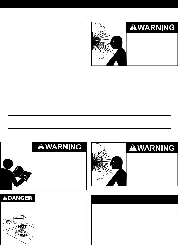
Read and understand this instruction manual and the safety messages herein before installing, operating or servicing this water heater.
Failure to follow these instructions and safety messages could result in death or serious injury.
This manual must remain with the water heater.
Water temperature over 125°F (52°C) can cause severe burns instantly resulting in severe injury or death.
Children, the elderly and the physically or mentally disabled are at highest risk for scald injury.
Feel water before bathing or showering.
Temperature limiting devices such as mixing valves must be installed when required by codes and to ensure safe temperatures at fixtures.
Explosion Hazard
 Overheated water can cause water tank explosion.
 Properly sized temperature and pressure relief valve must be installed in the opening provided.
CAUTION
Improper installation, use and service may result in property damage.
•Do not operate water heater if exposed to flooding or water damage.
•Inspect anode rods regularly, replace if damaged.
•Install in location with drainage.
•Fill tank with water before operation.
•Properly sized thermal expansion tanks are required on all closed water systems.
Refer to this manual for installation and service.
4

GENERAL SAFETY INFORMATION
5
GENERAL SAFETY INFORMATION
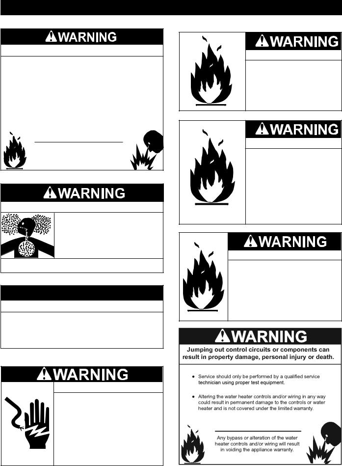
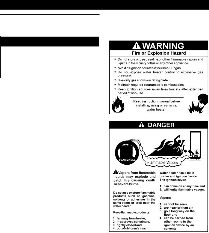
Fire or Explosion Hazard
 Do not store or use gasoline or other flammable vapors and liquids in the vicinity of this or any other appliance.
 Avoid all ignition sources if you smell gas.
 Do not expose water heater controls to excessive gas pressure.
 Use only the gas shown on the water heater rating plate.
 Maintain required clearances to combustibles.
 Keep ignition sources away from faucets after extended periods of non-use.
Read instruction manual before installing, using or servicing water heater.
Breathing Hazard - Carbon Monoxide Gas
 Do not obstruct water heater air intake
with insulating blanket.
 Gas and carbon monoxide detectors
are available.
 Install water heater in accordance with
the instruction manual.
Breathing carbon monoxide can cause brain damage or death. Always read and understand instruction manual.
CAUTION
Property Damage Hazard
•All water heaters eventually leak.
•Do not install without adequate drainage.
Electrical Shock Hazard
•Turn off power to the water heater before performing any service.
•Label all wires prior to disconnecting when performing service. Wiring errors can cause improper and dangerous operation.
•Verify proper operation after servicing.
•Failure to follow these instructions can result in personal injury or death.
Fire Hazard
For continued protection against risk of fire:
 Do not install water heater on carpeted floor.
 Do not operate water heater if exposed to flooding or water damage.
Fire and Explosion Hazard
 Use joint compound or Teflon tape compatible with propane gas.
 Leak test gas connections before placing the water heater in operation.
 Disconnect gas piping at main gas shutoff valve before leak testing.
 Install sediment trap in accordance with NFPA 54.
Fire and Explosion Hazard
 Do not use water heater with any gas other than the gas shown on the rating plate.
 Excessive gas pressure to gas valve can cause serious injury or death.
 Turn off gas lines during installation.
 Contact a qualified installer or service technician for installation and service.
6

INTRODUCTION
Thank You for purchasing this water heater. Properly installed and maintained, it should give you years of trouble free service.
ABBREVIATIONS USED
Abbreviations found in this Instruction Manual include :
•ANSI - American National Standards Institute
•ASME - American Society of Mechanical Engineers
•AHRI - Air-Conditioning, Heating and Refrigeration Institute
•NEC - National Electrical Code
•NFPA - National Fire Protection Association
•UL - Underwriters Laboratory
•CSA - Canadian Standards Association
QUALIFICATIONS
QUALIFIED INSTALLER OR SERVICE AGENCY
Installation and service of this water heater requires ability equivalent to that of a Qualified Agency (as defined by ANSI below) in the field involved. Installation skills such as plumbing, air supply, venting, gas supply and electrical supply are required in addition to electrical testing skills when performing service.
ANSI Z223.1 2006 Sec. 3.3.83: “Qualified Agency” - “Any individual, firm, corporation or company that either in person or through a representative is engaged in and is responsible for (a) the installation, testing or replacement of gas piping or (b) the connection, installation, testing, repair or servicing of appliances and equipment; that is experienced in such work; that is familiar with all precautions required; and that has complied with all the requirements of the authority having jurisdiction.”
If you are not qualified (as defined by ANSI above) and licensed or certified as required by the authority having jurisdiction to perform a given task do not attempt to perform any of the procedures described in this manual. If you do not understand the instructions given in this manual do not attempt to perform any procedures outlined in this manual.
ICOMM™ & BACNET COMPATIBLE
This water heater is compatible with the iCOMM™ remote monitoring system. The iCOMM™ system hardware and monitoring service is purchased separately. It allows users to monitor critical operational, diagnostic and energy usage data from a secure web site.
The iCOMM™ system can automatically notify selected personnel via email and/or cellular phone text messages if operational problems or user defined Alert Conditions occur.
iCOMM™ system hardware is compatible with BACnet compliant supervisory controls and building management systems. For more information call 888 928-3702
PREPARING FOR THE INSTALLATION
1.Read the entire manual before attempting to install or operate the water heater. Pay close attention to the General Safety Information on Page 4 through Page 6. If you don’t follow the safety rules, the water heater may not operate safely. It could cause property damage, injury and/or death.
This manual contains instructions for the installation, operation, and maintenance of the water heater. It also contains warnings throughout the manual that you must read and be aware of. All warnings and all instructions are essential to the proper operation of the water heater and your safety.
Detailed installation diagrams are also found in this manual.
These diagrams will serve to provide the installer with a reference. It is essential that all venting, water piping, gas piping and wiring be installed as shown.
Particular attention should be given to the installation of thermometers at the locations indicated in the piping diagrams as these are necessary for checking the operation of the water heater.
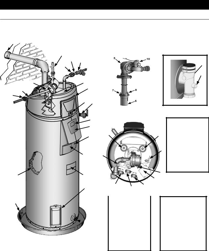
The principal components of the water heater are identified in
Features And Components on Page10 & Page 11 in this manual.
Use this reference to locate and identify various components on the water heater.
See the Installation Checklist and Troubleshooting on page 52. By using this checklist the user may be able to make minor operational adjustments and avoid unnecessary service calls. However, service and diagnostic procedures should only be performed by a Qualified Service Agency.
NOTE: Costs to correct installation errors are not covered under the limited warranty.
2.Be sure to turn off power when working on or near the electrical system of the water heater. Never touch electrical components with wet hands or when standing in water.
3.The installation must conform to all instructions contained in this manual and the local code authority having jurisdiction. These shall be carefully followed in all cases. Authorities having jurisdiction should be consulted before installation begins if there are any questions regarding compliance with local, state or national codes.
In the absence of local codes, the installation must comply with the current editions of the National Fuel Gas Code, ANSI Z223.1/NFPA 54 and the National Electrical Code, NFPA 70. All documents are available from the Canadian Standards Association, 8501 East Pleasant Valley Road, Cleveland, OH 44131. NFPA documents are also available from the National Fire Protection Association, 1 Batterymarch Park, Quincy,
MA 02269.
4.If after reading this manual you have any questions or do not understand any portion of the instructions, call the toll free number on the back cover of this manual for technical assistance. In order to expedite your request, please have the full Model, Serial and Series number of the water heater you are working with available for the technician. This information is located on the water heater’s rating plate.
5.Carefully plan the placement of the water heater. Examine the location to ensure that it complies with the requirements in Locating The Water Heater on Page 14 and the Rough In
Dimensions on Page 8.
.
6.For installation in California this water heater must be braced or anchored to avoid falling or moving during an earthquake. See instructions for correct installation procedures. Instructions may be obtained from California Office of the State Architect, 1102 Q Street, Suite 5100, Sacramento, CA 95811.
7.Massachusetts Code requires this water heater to be installed in accordance with Massachusetts 248-CMR 2.00: State Plumbing Code and 248-CMR 5. See Commonwealth of Massachusetts on Page 24.
7
DIMENSIONS AND CAPACITY DATA
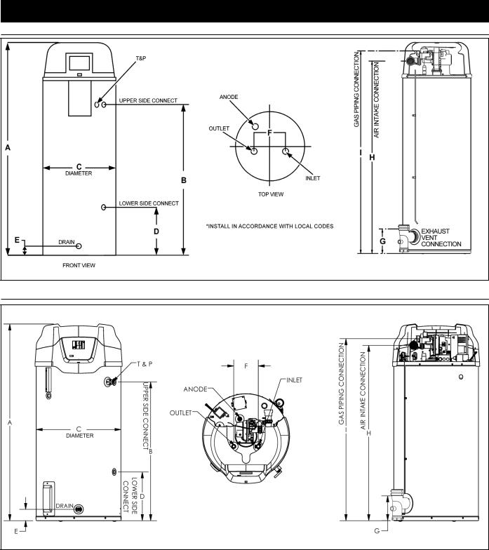
ROUGH IN DIMENSIONS: 50 GALLON UNIT
Figure 1: DIMENSIONS FOR 50 GALLON UNIT
ROUGH IN DIMENSIONS: 75 GALLON UNIT
Figure 1A: DIMENSIONS FOR 75 GALLON UNIT
Table 1 – ROUGH-IN-DIMENSIONS
|
Units |
A |
B |
C |
D |
E |
F |
G |
H |
I |
|
50G |
Inches |
66.75 |
49.25 |
22.00 |
15.75 |
3.00 |
8.00 |
8.00 |
62.00 |
65.00 |
|
cm |
169.5 |
125.09 |
55.88 |
40.00 |
7.62 |
20.32 |
20.32 |
157.48 |
165.1 |
||
|
|||||||||||
75G |
Inches |
64.71 |
45.64 |
27.75 |
16.00 |
3.71 |
8.00 |
7.93 |
57.36 |
58.98 |
|
|
|
|
|
|
|
|
|
|
|
||
cm |
164.4 |
115.9 |
70.5 |
40.6 |
9.4 |
20.3 |
20.1 |
145.7 |
149.8 |
||
|
Top Inlet and Outlet: 50G - 3/4” NPT; 75G - 1” NPT
Side Inlet and Outlet: 3/4” NPT
Gas Inlet: 1/2” NPT
Condensate drain outlet: 1/2” NPT
8

DIMENSIONS AND CAPACITY DATA
Table 2 – CAPACITY, GAS AND ELECTRICAL CHARACTERISTICS
Approximate Capacity |
*Manifold Pressure |
Electrical Characteristics |
||||
U.S. Gals. |
Liters |
Gas Type |
“WC |
kPA |
Volts/Hz |
Amperes |
50 |
189 |
Nat./LP |
0 |
0 |
120/60 |
<5 |
75 |
284 |
Nat/LP |
0 |
0 |
120/60 |
<5 |
*The manifold pressure is the factory setting and is not adjustable. A negative pressure will be seen with just the blower running without the Gas Control Valve open.
All models - Maximum Supply Pressure: 14 inches W.C. (3.48kPa)
Minimum Supply Pressure for Natural Gas: 3.50” (.87kPa)
Minimum Supply Pressure for Propane Gas: 8.00” (1.99kPa)
Minimum pressure must be maintained under both load and no load (dynamic and static) conditions.
|
|
|
|
|
|
|
Table 3 – RECOVERY CAPACITIES |
|
|
|
|
|
|
||||||
Input |
|
|
|
|
|
|
|
|
Recovery Capacities |
|
|
|
|
|
|
||||
Rating |
|
Rating |
Temp. |
F |
30 |
40 |
50 |
60 |
|
70 |
80 |
|
90 |
100 |
110 |
120 |
130 |
140 |
|
(Btu/hr) |
|
(kW) |
Rise |
|
C |
17 |
22 |
28 |
33 |
|
39 |
44 |
|
50 |
56 |
61 |
67 |
72 |
78 |
|
|
|
|
|
|
|
|||||||||||||
100,000 |
|
29.3 |
GPH |
|
387 |
291 |
233 |
194 |
|
166 |
145 |
|
129 |
116 |
106 |
97 |
90 |
83 |
|
|
LPH |
|
1465 |
1102 |
882 |
734 |
|
628 |
549 |
|
488 |
439 |
401 |
367 |
341 |
314 |
|||
|
|
|
|
|
|
||||||||||||||
Recovery capacity based on 96% thermal efficiency.
9
FEATURES AND COMPONENTS
50 GALLON UNIT
**29 |
|
|
|
|
|
|
|
|
|
20 |
|
|
|
|
|
|
|
|
|
23 |
22 |
|
|
|
|
|
|
|
|
21 |
|
|
|
|
|
|
|
|
|
5 |
1 |
|
|
|
|
|
|
|
|
18 |
|
12 |
|
|
|
|
|
|
|
|
|
|
|
|
|
|
|
|
|
21 |
|
|
|
|
|
|
|
|
|
|
16 |
25 |
|
|
|
|
|
|
|
|
|
|
|
|
|
|
|
|
|
|
|
11 |
|
|
|
|
|
|
|
|
|
|
|
|
|
|
|
|
|
|
|
17 |
|
|
|
|
|
|
|
|
|
33 |
|
24 |
|
|
|
|
|
|
|
|
|
|
|
|
|
|
|
|
13 |
|
19 |
|
|
|
|
|
|
32 |
26, 27 |
|
|
|
|
|
|
|
|
|
|
|
|
|
|
|
|
|
|
|
34 (SEE |
|
3 |
|
4 |
|
|||
|
ACCESS |
2 |
|
||||||
|
|
|
|
|
|
||||
|
PANEL |
|
|
|
|
|
|
|
|
|
CAUTION) |
|
|
|
|
|
|
||
30 |
|
|
|
|
|
|
VACUUM RELIEF |
|
|
|
|
|
|
|
|
|
VALVE |
|
|
 28
28
*INSTALL PER LOCAL CODES
*CAUTION HARNESS HAS 120 VAC. IN OPERATION.
**See Venting Installation and Condensate Piping for more information.
Figure 1B: 50 GALLON UNIT
**14
 **15
**15
ACCESS PANEL
18
35Caution: Thisaccesspanelcovers a 2” NPT plug that was required during the manufacturing of this water heater. This 2” NPT flange is notacleanoutfitting, removing the
2” NPT plug and using this fitting as acleanout could void your warranty.
31
9
10
FEATURES AND COMPONENTS (CONT.)
75 GALLON UNIT
**29
5
18
21
13 
32
30
20
22
23
21
12
11
17
25
 16
16
26, 27
33
34
 28
28
*CAUTION HARNESS HAS 120 VAC. IN OPERATION.
**See Venting Installation and Condensate Piping for more information.
24
3
2
4
19
VACUUM RELIEF
VALVE
*INSTALL PER LOCAL CODES
Figure 1C: 75 GALLON UNIT
**14
**15
1
18
 31
31
 35
35
 9
9
11

FEATURES AND COMPONENTS (CONT.)
1:Control Assembly
2:Blocked Intake Switch
3:Blocked Outlet Switch
4:Blower Prover Switch
5:Blower Assembly
6:Burner Assembly
7:Flame Sensor
8:Igniter Assembly
9:Junction Box
10:Gas Control Valve Assembly
11:Display Board
12:Top Plastic Enclosure
13:Display Enclosure
**14: Exhaust Elbow Assembly
**15: Condensate Drain Outlet
16:Enable / Disable Switch
17:Display Overlay
18:Hot Water Outlet
19:Gas Supply
20:Main Manual Gas Shutoff Valve
21:Union
22:Inlet Water Shutoff Valve
23:Cold Water Inlet
24:Inlet Dip Tube
25:T/P Relief Valve
26:Rating Plate
27:Labels
28:Drain Valve
**29: Vent Terminal
30:Drain Pan
31:Anode Rod
32:Insulation
33:Temperature Probe
34:Access Door
35:Spark Module
12
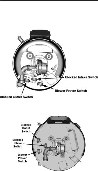
CONTROLS AND SWITCHES
This model is provided with three pressure switches. These switches are essential to the safe and proper operation of the unit. All switches are wired in series. The controller is set up to shut the unit down whenever there is a failure of any of the switches. It is important to understand the purpose of each switch.
50 GALLON UNIT
75 GALLON UNIT
Figure 2
BLOWER PROVER SWITCH
The Blower Prover Switch is provided on the heater to verify that the fan is operating. It is a positive pressure switch whose electrical contacts are normally open. When the fan increases the pressure in the burner, the pressure switch will allow the electrical contacts to
close. The pressure switch is connected to the blower pressure tap by a piece of tygon tubing. This tubing must be connected in order for the switch to change the electrical contacts. The controller requires that the electrical contacts on this air flow switch be open before it will allow the blower to come on.
BLOCKED OUTLET SWITCH
The Blocked Exhaust Switch is set up to shut the unit off when a buildup of positive pressure in the exhaust vent pipe occurs. This switch is a positive pressure switch that requires an increase in pressure to change the electrical contacts from normally closed to open. When this switch prevents the unit from igniting, most likely the exhaust is blocked by some means. Check to see if the condensate is allowed to flow freely from the exhaust elbow and for obstructions in the exhaust venting and exhaust vent terminal. Also verify that the vent length does not exceed the maximum allowed as shown in the Vent Section of this manual.
BLOCKED INTAKE SWITCH
The Blocked Intake Switch is set up to shut the unit off when a build-up of negative pressure in the intake air pipe occurs. This switch is a negative pressure switch that requires an increase in negative pressure to change the electrical contacts from normally closed to open. The switch is connected to the pressure tap on the PVC pipe connected to the inlet of the blower. When this switch prevents the unit from igniting, most likely the intake is blocked. Verify that the screen on the intake air connection (conventional vent), the intake air pipe and termination (direct vent installations) are free of obstructions that may prevent air from entering the unit. Insure the screen on intake air connection has been removed on direct vent installations, see Figure 13.Also verify the intake air pipe length does not exceed the maximum allowed as shown in the Vent Section of this manual.
WATER HEATING ENABLE/DISABLE SWITCH
IMPORTANT: The Enable/Disable switch listed in this manual is NOT an “on/off” switch and does not disconnect 120 volt power to the CCB and other heater components.
Water Heater’s Enable/Disable Switch. When in the “Disabled” position the switch removes electrical power from the gas valve so that water heating is disabled. The display, CCB, and other electrical components will still be energized and the display will read “Water Heating Disabled”.
SPARK IGNITER
The Spark Igniter is a device that ignites the main burner by spark.
When high voltage is applied to the igniter, spark is generated to ignite the main burner.
CONFIGURATION KEY
The configuration |
key is |
located inside |
the control box. |
It provides for the |
ability |
of the heater to |
retain information |
collected over its lifetime, even if the control board is replaced because of failure.
The configuration key should stay with the heater.
13
INSTALLATION CONSIDERATIONS
LOCATING THE WATER HEATER
Carefully choose a location for the new water heater. The placement is a very important consideration for the safety of the occupants in the building and for the most economical use of the water heater.
CAUTION
Property Damage Hazard
•All water heaters eventually leak.
•Do not install without adequate drainage.
Whether replacing an existing water heater or installing the water heater in a new location observe the following critical points:
1.The water heater must be located indoors.
2.The water heater must not be located in an area where it will be subject to freezing temperatures.
3.Locate the water heater so it is protected and not subject to physical damage by a moving vehicle.
4.Locate the water heater on a level surface.
5.Locate the water heater near a floor drain. The water heater should be located in an area where leakage of the tank or connections will not result in damage to the area adjacent to the water heater or to lower floors of the structure. When such locations cannot be avoided, it is recommended that a metal drain pan, piped to adequate drain, be installed under the water heater. Drain pan should be fabricated with sides at least 2” deep with diameter at least 2” greater than diameter of heater. Pan must not restrict combustion air flow.
6.Locate the water heater close to the point of major hot water usage.
7.Locate the water heater close to a 120 VAC power supply. See Power Supply on Page 18 for requirements.
8.Locate the water heater where an adequate supply of fresh air for combustion and ventilation can be obtained. See
Combustion Air and Ventilation on Page 15.
9.Locate the water heater where the vent and intake air piping, when installed, will remain within the maximum equivalent lengths allowed. See Venting Installation on page 25.
10.Do not locate the water heater where noise (such as the Combustion Blower) during normal operation will be objectionable in adjacent areas.
11.Do not locate the water heater where the subsequent installation of the vent (exhaust) or intake air terminations would be objectionable due to noise at the termination(s). This includes locations close to or across from windows and doors. See Venting Installation on page 25.
Do not locate water heater areas where flammable liquids (vapors) are likely to be present or stored (garages, storage and utility areas, etc.): Flammable liquids (such as gasoline, solvents, propane (LP or butane, etc.) and other substances
(such as adhesives, etc.) emit flammable vapors which can be ignited by a gas water heater’s ignition device or main burner. The resulting flashback and fire can cause death or serious burns to anyone in the area.
Also, the water heater must be located and/or protected so it is not subject to physical damage by a moving vehicle.
When the water heater is installed directly on carpeting, the water heater shall be installed on a metal or wood panel extending beyond the full width and depth of the water heater by at least 3 in (76.2 mm) in any direction or, if the water heater is installed in an alcove or closet, the entire floor shall be covered by the panel. The panel must be strong enough to carry the weight of the heater when full of water.
14
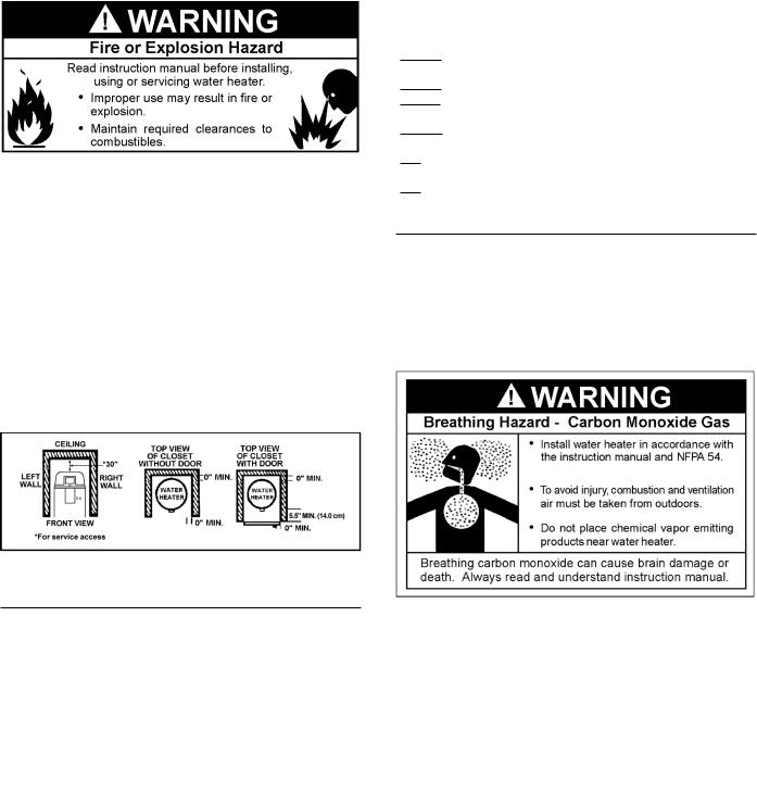
Minimum clearances between the water heater and combustible construction are 0 inch at the sides and rear, 5.5” (14.0 cm) from the front and 18” (45.7 cm) from the top. (Standard clearance.) If clearances stated on the heater differ from standard clearances, install water heater according to clearances stated on the heater.
Adequate clearance 30” (76 cm) for servicing this water heater should be considered before installation, such as changing the anode rods, control system components and gas control valve.
A minimum clearance of 5.5” (14.0 cm) must be allowed for access to replaceable and/orserviceableparts suchasthethermostats,drainvalve, condensate drain, temperature-pressure relief valve, clean out opening, and the vent connection (exhaust elbow).
When installing the heater, consideration must be given to proper location. Location selected should be as close to the wall as practicable and as centralized with the water piping system as possible.
Figure 3: CLEARANCES
INSULATION BLANKETS
Insulation blankets are available to the general public for external use on gas water heaters but are not necessary with these products. The purpose of an insulation blanket is to reduce the standby heat loss encountered with storage tank heaters. Your water heater meets or exceeds the Energy PolicyAct standards with respect to insulation and standby loss requirements, making an insulation blanket unnecessary.
Should you choose to apply an insulation blanket to this heater, you should follow these instructions (For identification of components
mentioned below, see Figure 1B & Figure 1C). Failure to follow these instructions can restrict the air flow required for proper combustion, potentially resulting in fire, asphyxiation, serious personal injury or death.
•Do not apply insulation to the top of the water heater, as this will interfere with safe operation of the blower assembly.
•Do not cover the control system LCD on top of the water heater.
•Do not cover the outer door, thermostat or temperature & pressure relief valve.
•Do not cover the instruction manual. Keep it on the side of the water heater or nearby for future reference.
•Do obtain new warning and instruction labels from the manufacturer for placement on the blanket directly over the existing labels.
•Do inspect the insulation blanket frequently to make certain it does not sag, thereby obstructing combustion air flow.
COMBUSTION AIR AND VENTILATION
A gas water heater cannot operate properly without the correct amount of air for combustion. Do not install in a confined area such as a closet, unless you provide air as shown in the Locating The Water Heater section. Never obstruct the flow of ventilation air. If you have any doubts or questions at all, call your gas supplier. Failure to provide the proper amount of combustion air can result in a fire or explosion and cause death, serious bodily injury, or property damage.
Figure 4: COMBUSTION AIR AND VENTILATION
If this water heater will be used in beauty shops, barber shops, cleaning establishments, or self-service laundries with dry cleaning equipment, it is imperative that the water heater(s) be installed direct vent so that all air for combustion and ventilation is taken from outdoors.
Propellants of aerosol sprays and volatile compounds, (cleaners, chlorine based chemicals, refrigerants, etc.) in addition to being highly flammable in many cases, will also react to form corrosive acids when exposed to the combustion products of the water heater. The results can be hazardous, and also cause product failure.
15
UNCONFINED SPACE
An Unconfined Space is one whose volume IS NOT LESS THAN 50 cubic feet per 1,000 Btu/hr (4.8 cubic meters per kW) of the total input rating of all appliances installed in the space. Rooms communicating directly with the space, in which the appliances are installed, through openings not furnished with doors, are considered a part of the unconfined space.
Makeup air requirements for the operation of exhaust fans, kitchen ventilation systems, clothes dryers and fireplaces shall also be considered in determining the adequacy of a space to provide combustion, ventilation and dilution air.
UNUSUALLY TIGHT CONSTRUCTION
In unconfined spaces in buildings, infiltration may be adequate to provide air for combustion, ventilation and dilution of flue gases. However, in buildings of unusually tight construction (for example, weather stripping, heavily insulated, caulked, vapor barrier, etc.) additional air must be provided using the methods described in the Confined Space section that follows.
CONFINED SPACE
A Confined Space is one whose volume IS LESS THAN 50 cubic feet per 1,000 Btu/hr (4.8 cubic meters per kW) of the total input rating of all appliances installed in the space.
Openings must be installed to provide fresh air for combustion, ventilation and dilution in confined spaces. The required size for the openings is dependent on the method used to provide fresh air to the confined space AND the total Btu/hr input rating of all appliances installed in the space.
DIRECT VENT APPLIANCES
Appliances installed in a Direct Vent configuration that derive all air for combustion from the outdoor atmosphere through sealed intake air piping are not factored in the total appliance input Btu/hr calculations used to determine the size of openings providing fresh air into confined spaces.
EXHAUST FANS
Where exhaust fans are installed, additional air shall be provided to replace the exhausted air. When an exhaust fan is installed in the same space with a water heater, sufficient openings to provide fresh air must be provided that accommodate the requirements for all appliances in the room and the exhaust fan. Undersized openings will cause air to be drawn into the room through the water heater’s vent system causing poor combustion. Sooting, serious damage to the water heater and the risk of fire or explosion may result. It can also create a risk of asphyxiation.
LOUVERS AND GRILLES
The free areas of the fresh air openings in the instructions that follow do not take in to account the presence of louvers, grilles or screens in the openings.
The required size of openings for combustion, ventilation and dilution air shall be based on the net free area of each opening. Where the free area through a design of louver or grille or screen is known, it shall be used in calculating the size of opening required to provide the free area specified. Where the louver and grille design and free area are not known, it shall be assumed that wood louvers will have 25% free area and metal louvers and grilles will have 75% free area. Non motorized louvers and grilles shall be fixed in the open position.
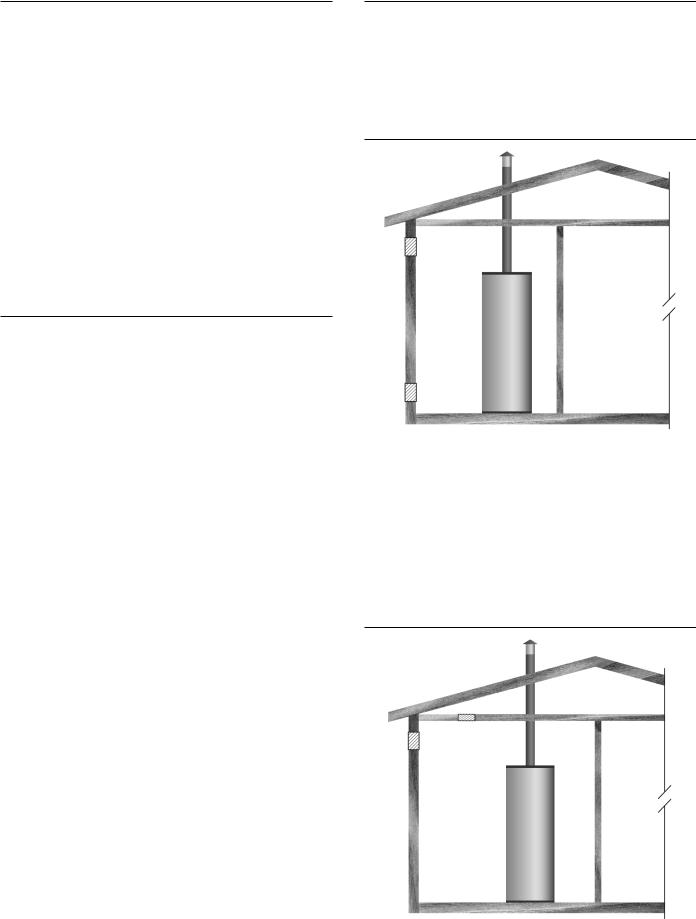
FRESH AIR OPENINGS FOR CONFINED SPACES
The following instructions shall be used to calculate the size, number and placement of openings providing fresh air for combustion, ventilation and dilution in confined spaces. The illustrations shown in this section of the manual are a reference for the openings that provide fresh air into confined spaces only. DO NOT refer to these illustrations for the purpose of vent installation. See Venting
Installation on Page 25 for complete venting installation instructions.
OUTDOOR AIR THROUGH TWO OPENINGS
Figure 5
The confined space shall be provided with two permanent openings, one commencing within 12 inches (300 mm) of the top and one commencing within 12 inches (300 mm) of the bottom of the enclosure. The openings shall communicate directly with the outdoors. See Figure 5.
Each opening shall have a minimum free area of 1 square inch per 4,000 Btu/hr (550 mm2 per kW) of the aggregate input rating of all appliances installed in the enclosure. Each opening shall not be less than 100 square inches (645 cm2).
OUTDOOR AIR THROUGH ONE OPENING
Figure 6
16
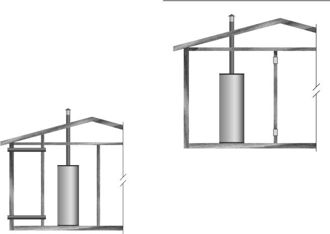
Alternatively a single permanent opening, commencing within 12 inches (300 mm) of the top of the enclosure, shall be provided. See Figure 6. The water heater shall have clearances of at least 1 inch (25 mm) from the sides and back and 6 inches (150 mm) from the front of the appliance. The opening shall directly communicate with the outdoors or shall communicate through a vertical or horizontal duct to the outdoors or spaces that freely communicate with the outdoors and shall have a minimum free area of the following:
1.1 square inch per 3000 Btu/hr (733 mm2 per kW) of the total input rating of all appliances located in the enclosure, and
2.Not less than the sum of the areas of all vent connectors in the space.
OUTDOOR AIR THROUGH TWO HORIZONTAL DUCTS
Figure 7
The confined space shall be provided with two permanent horizontal ducts, one commencing within 12 inches (300 mm) of the top and one commencing within 12 inches (300 mm) of the bottom of the enclosure. The horizontal ducts shall communicate directly with the outdoors. See Figure 7.
Each duct opening shall have a minimum free area of 1 square inch per 2,000 Btu/hr (1100 mm2 per kW) of the aggregate input rating of all appliances installed in the enclosure.
When ducts are used, they shall be of the same cross sectional area as the free area of the openings to which they connect. The minimum dimension of rectangular air ducts shall be not less than 3 inches.
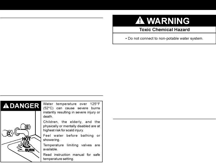
AIR FROM OTHER INDOOR SPACES
Figure 8
The confined space shall be provided with two permanent openings, one commencing within 12 inches (300 mm) of the top and one commencing within 12 inches (300 mm) of the bottom of the enclosure. See Figure 8.
Each opening shall communicate directly with an additional room(s) of sufficient volume so that the combined volume of all spaces meets the criteria for an Unconfined Space.
Each opening shall have a minimum free area of 1 square inch per 1,000 Btu/hr (2200 mm2 per kW) of the aggregate input rating of all appliances installed in the enclosure. Each opening shall not be less than 100 square inches (645 cm2).
17
INSTALLATION REQUIREMENTS
CHEMICAL VAPOR CORROSION
Corrosion of the flueways and vent system may occur if air for combustion contains certain chemical vapors. Such corrosion may result in failure and risk of asphyxiation.
Spray can propellants, cleaning solvents, refrigerator and air conditioning refrigerants, swimming pool chemicals, calcium and sodium chloride (water softener salt), waxes, and process chemicals are typical compounds which are potentially corrosive.
Do not store products of this sort near the heater. Also, air which is brought in contact with the heater should not contain any of these chemicals. If necessary, uncontaminated air should be obtained from remote or outside sources. The limited warranty is voided when failure of water heater is due to a corrosive atmosphere. (See limited warranty for complete terms and conditions).
WATER PIPING
HOTTER WATER CAN SCALD:
Water heaters are intended to produce hot water. Water heated to a temperature which will satisfy space heating, clothes washing, dish washing, cleaning and other sanitizing needs can scald and permanently injure you upon contact. Some people are more likely to be permanently injured by hot water than others. These include the elderly, children, the physically or developmentally disabled. If anyone using hot water fits into one of these groups or if there is a local code or state law requiring a certain temperature water at the hot water tap, then you must take special precautions. In addition to using the lowest possible temperature setting that satisfies your hot water needs, a means such as a mixing valve should be used at the hot water taps used by these people or at the water heater. Valves for reducing point of use temperature by mixing cold and hot water are also available:
Consult a Qualified Installer or Service Agency. Follow manufacturer’s instructions for installation of the valves. Before changing the factory setting on the thermostat, read the Temperature Regulation section in this manual.
This water heater shall not be connected to any heating systems or component(s) used with a non-potable water heating appliance.
All piping components connected to this unit for space heating applications shall be suitable for use with potable water.
Toxic chemicals, such as those used for boiler treatment shall not be introduced into this system.
When the system requires water for space heating at temperatures higher than required for domestic water purposes, a mixing valve must be installed.
These water heaters cannot be used in space heating applications only.
POWER SUPPLY
The water heaters covered in this manual require a 120 VAC, 1Ø (single phase), 60Hz, 5 amp power supply and must also be electrically grounded in accordance with local codes or, in the absence of local codes, with the National Electrical Code, ANSI/NFPA 70.
If any of the original wire as supplied with the water heater must be replaced, it must be replaced with 105°C rated wiring or its equivalent, except in the burner housing. In this case 200°C rated wire must be used.
DEDICATED POWER WIRING AND BREAKERS
Dedicated power supply wires, ground wiring and dedicated circuit breakers often prevent electrical line noise and should be considered when installing the water heater.
POWER FLUCTUATIONS AND ELECTRICAL NOISE
The water heater’s control system requires a source of stable clean electricity for proper operation. Connecting the water heater to a branch circuit that is subject to fluctuations in voltage level or electrical line noise such as EMI (electro magnetic interference) or RFI (radio frequency interference) may cause erratic control system operation and malfunction.
A high quality power supply filter/suppressor must be installed if the above conditions exist. Call the technical support phone number listed on the back cover of this manual for more information.
NOTE: Malfunctions caused by the power supply and the costs to install power supply filters are not covered under the limited warranty.
18
Loading...