


 Loading...
Instruction Manual
COMMERCIAL LIGHT DUTY ELECTRIC WATER HEATERS
Thank you for buying this energy efficient water heater. We appreciate your confidence in our products.
Read and understand this instruction manual and the safety messages herein before installing, operating or servicing this water heater.
Failure to follow these instructions and safety messages could result in death or serious injury.
This manual must remain with the water heater.
Compact 6/10/15/20 Models Series 102 Lowboy 30/40/50 Models Series 110 Tall 30/40/52/66/80/120 Models Series 110
INSTALLATION - OPERATION - SERVICE - MAINTENANCE
Electrical Shock Hazard
If the water heater becomes immersed in water up to or above the level of the bottom of the element doors,
the heater should be examined by a qualified service agency before it is placed in operation.
PLACE THESE INSTRUCTIONS ADJACENT TO HEATER AND NOTIFY OWNER TO KEEP FOR FUTURE REFERENCE.
PRINTED 0618 |
100303948 2000199954 (Rev. H) |
|
1
SAFE INSTALLATION, USE, AND SERVICE
The proper installation, use and servicing of this water heater is extremely important to your safety and the safety of others.
Many safety-related messages and instructions have been provided in this manual and on your own water heater to warn you and others of a potential injury hazard. Read and obey all safety messages and instructions throughout this manual. It is very important that the meaning of each safety message is understood by you and others who install, use, or service this water heater.
This is the safety alert symbol. It is used to alert you to potential personal injury hazards. Obey all safety messages that follow this symbol to avoid possible injury or death.
DANGER indicates an imminently
DANGER hazardous situation which, if not avoided, will result in injury or death.
WARNING indicates a potentially hazardous
WARNING situation which, if not avoided, could result in injury or death.
CAUTION indicates a potentially hazardous
CAUTION situation which, if not avoided, could result in minor or moderate injury.
CAUTION used without the safety alert CAUTION symbol indicates a potentially hazardous
situation which, if not avoided, could result in property damage.
All safety messages will generally tell you about the type of hazard, what can happen if you do not follow the safety message, and how to avoid the risk of injury.
IMPORTANT DEFINITIONS
•Qualified Installer or Service Agency
Installation and service of this water heater requires ability equivalent to that of a Qualified Agency (as defined by ANSI below) in the field involved. Installation skills, such as plumbing, air supply, venting, gas supply, and electrical supply are required in addition to electrical testing skills when performing service.
•ANSI Z223.1 2006 Sec. 3.3.83:
“Qualified Agency” - “Any individual, firm, corporation or company that either in person or through a representative is engaged in and is responsible for (a) the installation, testing or replacement of gas piping or (b) the connection, installation, testing, repair or servicing of appliances and equipment; that is experienced in such work; that is familiar with all precautions required; and that has complied with all the requirements of the authority having jurisdiction.”
2

GENERAL SAFETY INFORMATION |
PRECAUTIONS |
|
HYDROGEN GAS (FLAMMABLE) |
DO NOT USE THIS WATER HEATER IF ANY PART HAS BEEN EXPOSED TO FLOODING OR WATER DAMAGE. Immediately call a qualified service technician to inspect the water heater and to replace any part of the control system which has been under water.
If the unit is exposed to the following, do not operate heater until all corrective steps have been made by a qualified service technician.
1.External fire.
2.Damage.
3.Firing without water.
GROUNDING INSTRUCTIONS
This water heater must be grounded in accordance with the National Electrical Code and/or local codes. These must be followed in all cases.
This water heater must be connected to a grounded metal, permanent wiring system; or an equipment grounding conductor must be run with the circuit conductors and connected to the equipment grounding terminal or lead on the water heater.
Hydrogen gas can be produced in a hot water system served by this heater that has not been used for a long period of time (generally two weeks or more). Hydrogen gas is extremely flammable. To reduce the risk of injury under these conditions, it is recommended that the hot water faucet be opened for several minutes at the kitchen sink before using any electrical appliance connected to the hot water system. If hydrogen is present there will probably be an unusual sound such as air escaping through the pipe as the water begins to flow. THERE SHOULD BE NO SMOKING OR OPEN FLAME NEAR THE FAUCET AT THE TIME IT IS OPEN.
When servicing this unit, verify the power to the unit is turned off prior to opening the control cabinet door.
Read and understand this instruction manual and the safety messages herein before installing, operating or servicing this water heater.
Failure to follow these instructions and safety messages could result in death or serious injury.
This manual must remain with the water heater.
CAUTION
Improper installation, use and service may result in property damage.
•Do not operate water heater if exposed to flooding or water damage.
•Inspect anode rods regularly, replace if damaged.
•Install in location with drainage.
•Fill tank with water before operation.
•Properly sized thermal expansion tanks are required on all closed water systems.
Refer to this manual for installation and service.
Explosion Hazard
 Flammable hydrogen gases may be present.
Keep all ignition sources away from faucet when turning on hot water.
Electrical Shock Hazard
•Turn off power at the branch circuit breaker serving the water heater before performing any service.
•Label all wires prior to disconnecting when performing service. Wiring errors can cause improper and dangerous operation.
•Verify proper operation after servicing.
•Failure to follow these instructions can result in personal injury or death.
Water temperature over 125°F (52°C) can cause severe burns instantly resulting in severe injury or death.
Children, the elderly and the physically or mentally disabled are at highest risk for scald injury.
Feel water before bathing or showering.
Temperature limiting devices such as mixing valves must be installed when required by codes and to ensure safe temperatures at fixtures.
Explosion Hazard
 Overheated water can cause water tank explosion.
Properly sized temperature and pressure relief valve must be installed in the opening provided.
3
TABLE OF
OF CONTENTS
GENERAL SAFETY INFORMATION.................................. |
3 |
Precautions..................................................................... |
3 |
Hydrogen Gas (Flammable)............................................ |
3 |
INTRODUCTION................................................................. |
4 |
Abbreviations Used......................................................... |
4 |
Preparing for the Installation........................................... |
4 |
DIMENSIONS AND CAPACITIES DATA............................. |
5 |
APPROVALS....................................................................... |
6 |
MODEL AND RATING......................................................... |
6 |
FEATURES AND COMPONENTS...................................... |
7 |
Electronic Control Models............................................... |
7 |
LOCATING THE NEW WATER HEATER............................ |
8 |
Facts to Consider About the Location............................. |
8 |
Clearances...................................................................... |
8 |
INSTALLATION................................................................... |
9 |
Required Ability............................................................... |
9 |
General........................................................................... |
9 |
Mixing Valve Usage:........................................................ |
9 |
Contaminated Water....................................................... |
9 |
Circulating Pump............................................................. |
9 |
Insulation Blankets......................................................... |
10 |
Hard Water..................................................................... |
10 |
Closed Water Systems................................................... |
10 |
Thermal Expansion........................................................ |
10 |
Temperature-Pressure Relief Valve............................... |
10 |
ELECTRICAL.................................................................... |
12 |
General.......................................................................... |
12 |
Branch Circuit................................................................ |
12 |
Calculating Amperage/Over-Current Protection............. |
12 |
WIRING DIAGRAMS......................................................... |
13 |
OPERATION..................................................................... |
14 |
General.......................................................................... |
14 |
Filling the Water Heater................................................. |
14 |
Initial Start Up................................................................ |
14 |
Draining the Water Heater............................................. |
14 |
TEMPERATURE REGULATION....................................... |
15 |
Temperature Adjustment................................................ |
15 |
MAINTENANCE................................................................ |
16 |
General.......................................................................... |
16 |
ANODE ROD Maintenance............................................ |
16 |
Temperature-Pressure Relief Valve Test........................ |
16 |
TROUBLESHOOTING CHECKLIST................................. |
17 |
Checklist........................................................................ |
17 |
Leakage Checkpoints.................................................... |
18 |
INTRODUCTION
Thank You for purchasing this boiler. Properly installed and maintained, it should give you years of trouble-free service.
ABBREVIATIONS USED
Abbreviations found in this Instruction Manual include:
•ANSI - American National Standards Institute
•ASME - American Society of Mechanical Engineers
•NEC - National Electrical Code
•NFPA - National Fire Protection Association
•UL - Underwriters Laboratory
•CSA - Canadian Standards Association
PREPARING FOR THE INSTALLATION
Electrical Shock Hazard
•Turn off power at the branch circuit breaker serving the water heater before performing any service.
•Label all wires prior to disconnecting when performing service. Wiring errors can cause improper and dangerous operation.
•Verify proper operation after servicing.
•Failure to follow these instructions can result in personal injury or death.
1.Read the “General Safety Information” section of this manual first and then the entire manual carefully. If you don’t follow the safety rules, the water heater may not operate safely. It could cause DEATH, SERIOUS BODILY INJURY AND/OR PROPERTY DAMAGE.
This manual contains instructions for the installation, operation, and maintenance of the electric water heater. It also contains warnings throughout the manual that
you must read and be aware of. All warnings and all instructions are essential to the proper operation of the water heater and your safety. READ THE ENTIRE
MANUAL BEFORE ATTEMPTING TO INSTALL OR OPERATE THE WATER HEATER.
Be sure to turn off power when working on or near the electrical system of the heater. Never touch electrical components with wet hands or when standing in water. When replacing fuses always use the correct size for the circuit, see Wiring Diagrams (page 13).
The model and rating plates on page 6 interpret certain markings into useful information. Both of these references should be used to identify the heater, its components and optional equipment.
2.The installation must conform with these instructions and the local code authority having jurisdiction and the requirements of the power company. In the absence of local codes, the installation must comply with the latest editions of the National Electrical Code, NFPA70 or the Canadian Electrical Code CSA C22.1. The National Electrical Code may be ordered from: National Fire Protection Association, 1 Batterymarch Park, Quincy, MA 02269. The Canadian Electrical Code is available from the Canadian StandardsAssociation, 8501 East Pleasant Valley Road, Cleveland, OH 44131.
3.If after reading this manual you have any questions or do not understand any portion of the instructions, call the toll free number listed on the water heater label for technical assistance.
A sample rating plate is shown on page 6 of this manual. In order to expedite your request, please have full model and serial number available for the technician.
4.Carefully plan your intended placement of the water heater. Examine the location to ensure the water heater complies with the “Locating the New Water Heater” section in this manual.
Installation and service of this water heater requires ability equivalent to that of a licensed tradesman or qualified agency (see Important Definitions on page 2) in the field involved. Plumbing and electrical work are required.
4
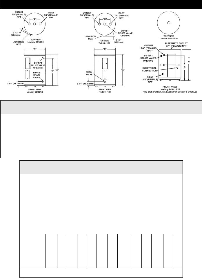
DIMENSIONS AND CAPACITIES DATA
Figure 1. Dimensions and Capacities for Each Type of Water Heater
Table 1. Rough-In Dimensions
|
|
Tank Capacity |
|
A |
|
B |
|
C |
|
D |
Approx. |
||||||
Models |
No. of |
|
|
|
|
Shipping Weight |
|||||||||||
|
|
|
|
|
|
|
|
|
|
|
|
|
|
||||
Dimensions |
Elements |
US Gals. |
Liters |
inches |
|
mm |
inches |
|
mm |
inches |
|
mm |
inches |
|
mm |
Lbs. |
Kg. |
Compact-6 |
1 |
6 |
23 |
15 1/2 |
|
394 |
14 1/4 |
|
362 |
11 |
|
279 |
- |
|
- |
35 |
15.9 |
Compact-10 |
1 |
10 |
38 |
18 1/4 |
|
464 |
18 |
|
457 |
12 1/2 |
|
318 |
- |
|
- |
54 |
24.5 |
Compact-15 |
1 |
15 |
57 |
26 |
|
660 |
18 |
|
457 |
20 1/2 |
|
521 |
- |
|
- |
58 |
26.3 |
Compact-20 |
1 |
20 |
76 |
22 1/4 |
|
565 |
21 3/4 |
|
552 |
15 3/8 |
|
391 |
- |
|
- |
73 |
33.1 |
Lowboy-30 |
2 |
30 |
114 |
30 7/8 |
|
784 |
21 3/4 |
|
552 |
24 1/8 |
|
613 |
8 |
|
203 |
100 |
45.4 |
Lowboy-40 |
2 |
40 |
151 |
32 1/4 |
|
819 |
24 |
|
610 |
25 9/16 |
|
649 |
8 |
|
203 |
125 |
56.7 |
Lowboy-50 |
2 |
50 |
189 |
32 1/4 |
|
819 |
26 1/2 |
|
673 |
25 1/8 |
|
638 |
8 |
|
203 |
166 |
75.3 |
Tall-30 |
2 |
30 |
114 |
34 1/2 |
|
876 |
20 1/2 |
|
521 |
- |
|
- |
8 |
|
203 |
98 |
44.5 |
Tall-40 |
2 |
40 |
151 |
45 1/8 |
|
1146 |
20 1/2 |
|
521 |
- |
|
- |
8 |
|
203 |
113 |
51.3 |
Tall-52 |
2 |
50 |
189 |
54 7/8 |
|
1394 |
20 1/2 |
|
521 |
- |
|
- |
8 |
|
203 |
131 |
59.4 |
Tall-66 |
2 |
66 |
250 |
60 3/4 |
|
1543 |
21 3/4 |
|
552 |
- |
|
- |
8 |
|
203 |
176 |
79.8 |
Tall-80 |
2 |
80 |
303 |
59 3/8 |
|
1508 |
24 |
|
610 |
- |
|
- |
8 |
|
203 |
211 |
95.7 |
Tall-120 |
2 |
119 |
450 |
62 7/16 |
|
1586 |
29 3/8 |
|
746 |
- |
|
- |
8 |
|
203 |
326 |
147.9 |
Table 2. U.S. Gallons/Hr and Litres/Hr at TEMPERATURE RISE INDICATED
Element |
INPUT |
F° |
36 F° |
40 F° |
54 F° |
60 F° |
72 F° |
80 F° |
90 F° |
100° F |
108 F° |
120 F° |
126 F° |
|
Wattage |
|
|
|
|
|
|
|
|
|
|
|
|
||
KW |
C° |
20 C° |
22.2 C |
30C° |
33.3C° |
40C° |
44.4C° |
50C° |
55.5C° |
60C° |
66.6C° |
70C° |
||
(Upper/Lower) |
||||||||||||||
|
|
|
|
|
|
|
|
|
|
|
|
|
||
|
|
|
|
NON |
-SIMULTANEOUS |
|
|
|
|
|
|
|||
/1500 |
|
GPH |
17 |
15 |
11 |
10 |
8 |
8 |
7 |
6 |
6 |
5 |
5 |
|
|
1.5 |
LPH |
64 |
58 |
43 |
38 |
32 |
29 |
26 |
23 |
21 |
19 |
18 |
|
/2000 |
|
GPH |
23 |
20 |
15 |
14 |
11 |
10 |
9 |
8 |
8 |
7 |
6 |
|
|
2.0 |
LPH |
85 |
77 |
57 |
51 |
43 |
38 |
34 |
31 |
28 |
26 |
24 |
|
/2500 |
|
GPH |
28 |
25 |
19 |
17 |
14 |
13 |
11 |
10 |
9 |
8 |
8 |
|
|
2.5 |
LPH |
107 |
96 |
71 |
64 |
53 |
48 |
43 |
38 |
36 |
32 |
30 |
|
3000/3000 |
|
GPH |
34 |
30 |
23 |
20 |
17 |
15 |
14 |
12 |
11 |
10 |
10 |
|
|
3.0 |
LPH |
128 |
115 |
85 |
77 |
64 |
58 |
51 |
46 |
43 |
38 |
37 |
|
4000/4000 |
|
GPH |
45 |
41 |
30 |
27 |
23 |
20 |
18 |
16 |
15 |
14 |
13 |
|
|
4.0 |
LPH |
170 |
153 |
114 |
102 |
85 |
77 |
68 |
61 |
57 |
51 |
49 |
|
4500/4500 |
|
GPH |
51 |
46 |
34 |
30 |
25 |
23 |
20 |
18 |
17 |
15 |
14 |
|
|
4.5 |
LPH |
192 |
173 |
128 |
115 |
96 |
86 |
77 |
69 |
64 |
58 |
55 |
|
5000/5000 |
|
GPH |
56 |
51 |
38 |
34 |
28 |
25 |
23 |
20 |
19 |
17 |
16 |
|
|
5.0 |
LPH |
213 |
192 |
142 |
128 |
107 |
96 |
85 |
77 |
71 |
64 |
61 |
|
6000/6000 |
|
GPH |
68 |
61 |
45 |
41 |
34 |
30 |
27 |
24 |
23 |
20 |
19 |
|
|
6.0 |
LPH |
256 |
230 |
170 |
153 |
128 |
115 |
102 |
92 |
85 |
77 |
73 |
|
|
|
|
|
|
SIMULTANEOUS OPERATION |
|
|
|
|
|
||||
3000/3000 |
|
GPH |
68 |
61 |
45 |
41 |
34 |
30 |
27 |
24 |
23 |
20 |
19 |
|
|
6 |
LPH |
256 |
230 |
170 |
153 |
128 |
115 |
102 |
92 |
85 |
77 |
73 |
|
4000/4000 |
|
GPH |
90 |
81 |
60 |
54 |
45 |
41 |
36 |
32 |
30 |
27 |
26 |
|
|
8 |
LPH |
341 |
307 |
227 |
205 |
170 |
153 |
136 |
123 |
114 |
102 |
97 |
|
4500/4500 |
|
GPH |
101 |
91 |
68 |
61 |
51 |
46 |
41 |
36 |
34 |
30 |
29 |
|
|
9 |
LPH |
384 |
345 |
256 |
230 |
192 |
173 |
153 |
138 |
128 |
115 |
110 |
|
5000/5000 |
|
GPH |
113 |
101 |
75 |
68 |
56 |
51 |
45 |
41 |
38 |
34 |
32 |
|
|
10 |
LPH |
426 |
384 |
284 |
256 |
213 |
192 |
170 |
153 |
142 |
128 |
122 |
|
6000/6000 |
|
GPH |
135 |
122 |
90 |
81 |
68 |
61 |
54 |
49 |
45 |
41 |
39 |
|
|
12 |
LPH |
511 |
460 |
341 |
307 |
256 |
230 |
205 |
184 |
170 |
153 |
146 |
|
Recovery capacities at 100° F rise equal: for non-simultaneous element operation = 4.1 gal. x KW of one element; for simultaneous element operation = 4.1 gal. x 2/3 KW of both elements. For other rises multiply element KW as previously explained by 4.1 and divide by temperature rise. Full load current for single phase = total watts : voltage.
5
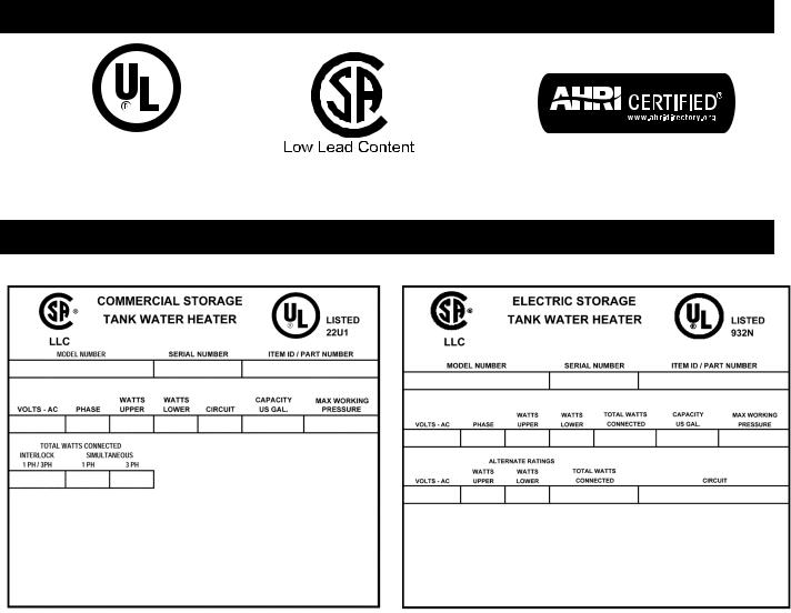
APPROVALS
All models are listed by
Underwriters Laboratories Inc.
MODEL AND RATING
Figure 2. Lowboy and Tall-30/40/66/80/120 |
Figure 3. Compact-6/10/15/20 |
||
|
|
|
|
6
Loading...