

Page 1

Instruction Manual
COMMERCIAL LIGHT DUTY ELECTRIC WATER HEATERS
Compact 6/10/15/20 Models Series 102
Lowboy 30/40/50 Models Series 110
Tall 30/40/52/66/80/120 Models Series 110
INSTALLATION - OPERATION - SERVICE
- MAINTENANCE
Thank you for buying this energy efcient water heater.
We appreciate your condence in our products.
Read and understand this instruction
manual and the safety messages
herein before installing, operating or
servicing this water heater.
Failure to follow these instructions and
safety messages could result in death
or serious injury.
This manual must remain with the
water heater.
PLACE THESE INSTRUCTIONS ADJACENT TO HEATER AND NOTIFY OWNER TO KEEP FOR FUTURE REFERENCE.
Electrical Shock Hazard
If the water heater becomes immersed in water up to or
above the level of the bottom of the element doors,
the heater should be examined by a qualified service
agency before it is placed in operation.
PRINTED 0618
100303948 2000199954 (Rev. H)
1
Page 2
SAFE INSTALLATION, USE, AND SERVICE
The proper installation, use and servicing of this water heater is extremely important to your safety and the safety of others.
Many safety-related messages and instructions have been provided in this manual and on your own water heater to warn
you and others of a potential injury hazard. Read and obey all safety messages and instructions throughout this manual.
It is very important that the meaning of each safety message is understood by you and others who install, use, or service
this water heater.
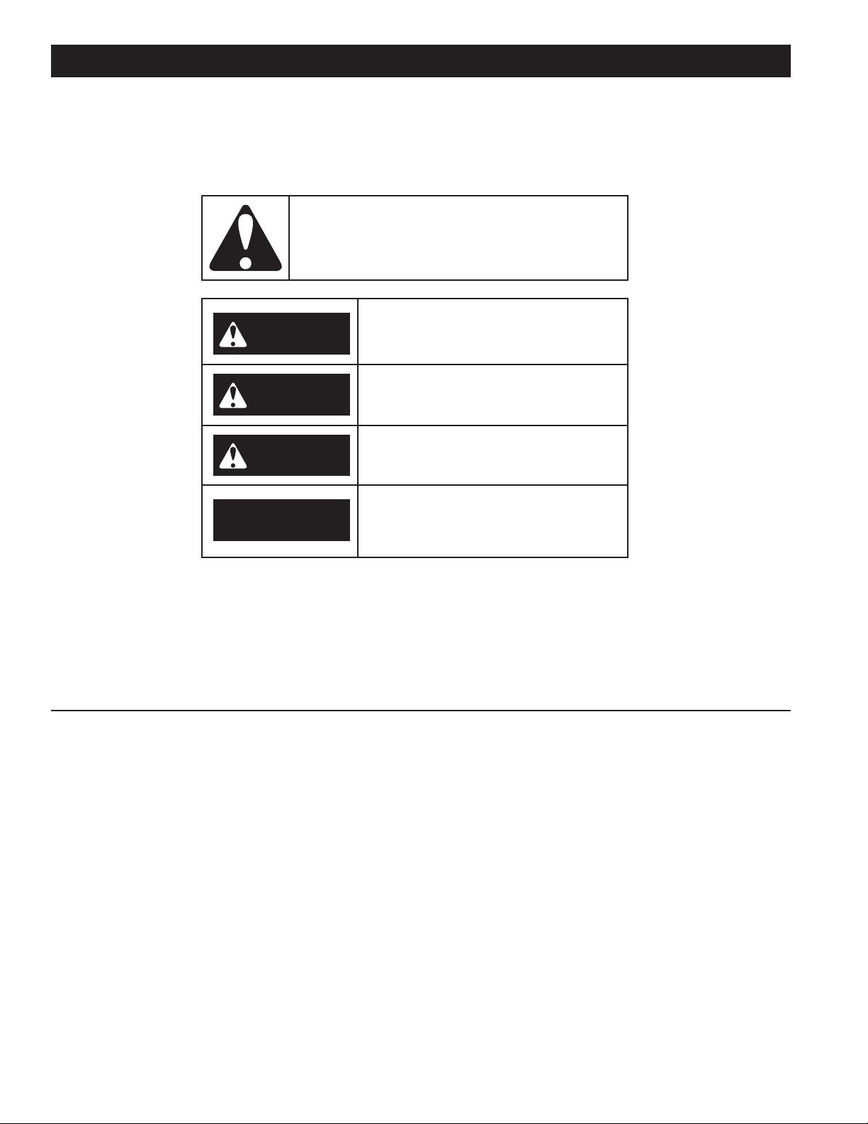
This is the safety alert symbol. It is used to alert you to
potential personal injury hazards. Obey all safety
messages that follow this symbol to avoid possible
injury or death.
DANGER indicates an imminently
DANGER
WARNING
CAUTION
hazardous situation which, if not avoided,
will result in injury or death.
WARNING indicates a potentially hazardous
situation which, if not avoided, could result
in injury or death.
CAUTION indicates a potentially hazardous
situation which, if not avoided, could result in
minor or moderate injury.
CAUTION used without the safety alert
CAUTION
All safety messages will generally tell you about the type of hazard, what can happen if you do not follow the safety message,
and how to avoid the risk of injury.
symbol indicates a potentially hazardous
situation which, if not avoided, could result in
property damage.
IMPORTANT DEFINITIONS
• Qualied Installer or Service Agency
Installation and service of this water heater requires ability equivalent to that of a Qualied Agency (as dened by ANSI
below) in the eld involved. Installation skills, such as plumbing, air supply, venting, gas supply, and electrical supply are
required in addition to electrical testing skills when performing service.
• ANSI Z223.1 2006 Sec. 3.3.83:
“Qualied Agency” - “Any individual, rm, corporation or company that either in person or through a representative is
engaged in and is responsible for (a) the installation, testing or replacement of gas piping or (b) the connection, installation,
testing, repair or servicing of appliances and equipment; that is experienced in such work; that is familiar with all precautions
required; and that has complied with all the requirements of the authority having jurisdiction.”
2
Page 3

GENERAL SAFETY INFORMATION
Water temperature over 125°F (52°C)
can cause severe burns instantly
resulting in severe injury or death.
Children, the elderly and the
physically or mentally disabled are at
highest risk for scald injury.
Feel water before bathing or
showering.
Temperature limiting devices such as
mixing valves must be installed
when required by codes and to
ensure safe temperatures at fixtures.
Explosion Hazard
Overheated water can cause
water tank explosion.
Properly sized temperature and
pressure relief valve must be
installed in the opening provided.
Improper installation, use and service may result
in property damage.
Do not operate water heater if exposed to flooding or
water damage.
•
Inspect anode rods regularly, replace if damaged.
•
Install in location with drainage.
•
Fill tank with water before operation.
•
Properly sized thermal expansion tanks are required on all
closed water systems.
•
Refer to this manual for installation and service.
CAUTION
Turn off power at the branch circuit
breaker serving the water heater
before performing any service.
Electrical Shock Hazard
•
Label all wires prior to disconnecting
when performing service. Wiring errors
can cause improper and dangerous
operation.
•
Verify proper operation after servicing.
•
Failure to follow these instructions can
result in personal injury or death.
•
Explosion Hazard
Flammable hydrogen gases
may be present.
Keep all ignition sources away
from faucet when turning on
hot water.
PRECAUTIONS
DO NOT USE THIS WATER HEATER IF ANY PART HAS BEEN
EXPOSED TO FLOODING OR WATER DAMAGE. Immediately
call a qualied service technician to inspect the water heater
and to replace any part of the control system which has been
under water.
If the unit is exposed to the following, do not operate heater until all
corrective steps have been made by a qualied service technician.
1. External re.
2. Damage.
3. Firing without water.
GROUNDING INSTRUCTIONS
This water heater must be grounded in accordance with the
National Electrical Code and/or local codes. These must be
followed in all cases.
This water heater must be connected to a grounded metal,
permanent wiring system; or an equipment grounding conductor
must be run with the circuit conductors and connected to the
equipment grounding terminal or lead on the water heater.
When servicing this unit, verify the power to the unit is turned off prior to opening the control cabinet door.
HYDROGEN GAS (FLAMMABLE)
Hydrogen gas can be produced in a hot water system served
by this heater that has not been used for a long period of time
(generally two weeks or more). Hydrogen gas is extremely
ammable. To reduce the risk of injury under these conditions, it
is recommended that the hot water faucet be opened for several
minutes at the kitchen sink before using any electrical appliance
connected to the hot water system. If hydrogen is present there
will probably be an unusual sound such as air escaping through
the pipe as the water begins to ow. THERE SHOULD BE NO
SMOKING OR OPEN FLAME NEAR THE FAUCET AT THE
TIME IT IS OPEN.
Read and understand this instruction
manual and the safety messages
herein before installing, operating or
servicing this water heater.
Failure to follow these instructions and
safety messages could result in death
or serious injury.
This manual must remain with the
water heater.
3
Page 4

Turn off power at the branch circuit
breaker serving the water heater
before performing any service.
Electrical Shock Hazard
•
Label all wires prior to disconnecting
when performing service. Wiring errors
can cause improper and dangerous
operation.
•
Verify proper operation after servicing.
•
Failure to follow these instructions can
result in personal injury or death.
•
TABLE OF CONTENTS
GENERAL SAFETY INFORMATION .................................. 3
Precautions ....................................................................3
Hydrogen Gas (Flammable) ...........................................3
INTRODUCTION ................................................................ 4
Abbreviations Used ........................................................4
Preparing for the Installation ..........................................4
DIMENSIONS AND CAPACITIES DATA ............................ 5
APPROVALS ...................................................................... 6
MODEL AND RATING ........................................................ 6
FEATURES AND COMPONENTS ..................................... 7
Electronic Control Models ..............................................7
LOCATING THE NEW WATER HEATER ........................... 8
Facts to Consider About the Location ............................8
Clearances .....................................................................8
INSTALLATION .................................................................. 9
Required Ability ..............................................................9
General ...........................................................................9
Mixing Valve Usage: .......................................................9
Contaminated Water .......................................................9
Circulating Pump ............................................................9
Insulation Blankets ........................................................10
Hard Water ....................................................................10
Closed Water Systems ..................................................10
Thermal Expansion .......................................................10
Temperature-Pressure Relief Valve ...............................10
ELECTRICAL ................................................................... 12
General ..........................................................................12
Branch Circuit ................................................................12
Calculating Amperage/Over-Current Protection ............12
WIRING DIAGRAMS ........................................................ 13
OPERATION ..................................................................... 14
General ..........................................................................14
Filling the Water Heater .................................................14
Initial Start Up ................................................................14
Draining the Water Heater .............................................14
TEMPERATURE REGULATION ...................................... 15
Temperature Adjustment ...............................................15
MAINTENANCE ............................................................... 16
General ..........................................................................16
ANODE ROD Maintenance ...........................................16
Temperature-Pressure Relief Valve Test .......................16
TROUBLESHOOTING CHECKLIST ................................ 17
Checklist ........................................................................17
Leakage Checkpoints ....................................................18
INTRODUCTION
Thank You for purchasing this boiler. Properly installed and
maintained, it should give you years of trouble-free service.
ABBREVIATIONS USED
Abbreviations found in this Instruction Manual include:
• ANSI - American National Standards Institute
• ASME - American Society of Mechanical Engineers
• NEC - National Electrical Code
• NFPA - National Fire Protection Association
• UL - Underwriters Laboratory
• CSA - Canadian Standards Association
PREPARING FOR THE INSTALLATION
1. Read the “General Safety Information” section of this manual
rst and then the entire manual carefully. If you don’t follow
the safety rules, the water heater may not operate safely. It
could cause DEATH, SERIOUS BODILY INJURY AND/OR
PROPERTY DAMAGE.
This manual contains instructions for the installation,
operation, and maintenance of the electric water heater.
It also contains warnings throughout the manual that
you must read and be aware of. All warnings and all
instructions are essential to the proper operation of
the water heater and your safety. READ THE ENTIRE
MANUAL BEFORE ATTEMPTING TO INSTALL OR
OPERATE THE WATER HEATER.
Be sure to turn off power when working on or near the
electrical system of the heater. Never touch electrical
components with wet hands or when standing in
water. When replacing fuses always use the correct size
for the circuit, see Wiring Diagrams (page 13).
The model and rating plates on page 6 interpret
certain markings into useful information. Both of these
references should be used to identify the heater, its
components and optional equipment.
2. The installation must conform with these instructions and the
local code authority having jurisdiction and the requirements
of the power company. In the absence of local codes, the
installation must comply with the latest editions of the National
Electrical Code, NFPA 70 or the Canadian Electrical Code CSA
C22.1. The National Electrical Code may be ordered from:
National Fire Protection Association, 1 Batterymarch Park,
Quincy, MA 02269. The Canadian Electrical Code is available
from the Canadian Standards Association, 8501 East Pleasant
Valley Road, Cleveland, OH 44131.
3. If after reading this manual you have any questions or do not
understand any portion of the instructions, call the toll free
number listed on the water heater label for technical assistance.
A sample rating plate is shown on page 6 of this
manual. In order to expedite your request, please have
full model and serial number available for the technician.
4. Carefully plan your intended placement of the water heater.
Examine the location to ensure the water heater complies with
the “Locating the New Water Heater” section in this manual.
Installation and service of this water heater requires ability
equivalent to that of a licensed tradesman or qualied
agency (see Important Denitions on page 2) in the
eld involved. Plumbing and electrical work are required.
4
Page 5

DIMENSIONS AND CAPACITIES DATA
Figure 1. Dimensions and Capacities for Each Type of Water Heater
Table 1. Rough-In Dimensions
Models
Dimensions
Compact-6 1 6 23 15 1/2 394 14 1/4 362 11 279 - - 35 15.9
Compact-10 1 10 38 18 1/4 464 18 457 12 1/2 318 - - 54 24.5
Compact-15 1 15 57 26 660 18 457 20 1/2 521 - - 58 26.3
Compact-20 1 20 76 22 1/4 565 21 3/4 552 15 3/8 391 - - 73 33.1
Lowboy-30 2 30 114 30 7/8 784 21 3/4 552 24 1/8 613 8 203 100 45.4
Lowboy-40 2 40 151 32 1/4 819 24 610 25 9/16 649 8 203 125 56.7
Lowboy-50 2 50 189 32 1/4 819 26 1/2 673 25 1/8 638 8 203 166 75.3
Tall-30 2 30 114 34 1/2 876 20 1/2 521 - - 8 203 98 44.5
Tall-40 2 40 151 45 1/8 1146 20 1/2 521 - - 8 203 113 51.3
Tall-52 2 50 189 54 7/8 1394 20 1/2 521 - - 8 203 131 59.4
Tall-66 2 66 250 60 3/4 1543 21 3/4 552 - - 8 203 176 79.8
Tall-80 2 80 303 59 3/8 1508 24 610 - - 8 203 2 11 95.7
Tall-120 2 11 9 450 62 7/16 1586 29 3/8 746 - - 8 203 326 147.9
No. of
Elements
Tank Capacity A B C D
US Gals. Liters inches mm inches mm inches mm inches mm Lbs. Kg.
Approx.
Shipping Weight
Table 2. U.S. Gallons/Hr and Litres/Hr at TEMPERATURE RISE INDICATED
Element
Wattage
(Upper/Lower)
/1500 GPH 17 15 11 10 8 8 7 6 6 5 5
/2000 GPH 23 20 15 14 11 10 9 8 8 7 6
/2500 GPH 28 25 19 17 14 13 11 10 9 8 8
3000/3000 GPH 34 30 23 20 17 15 14 12 11 10 10
4000/4000 GPH 45 41 30 27 23 20 18 16 15 14 13
4500/4500 GPH 51 46 34 30 25 23 20 18 17 15 14
5000/5000 GPH 56 51 38 34 28 25 23 20 19 17 16
6000/6000 GPH 68 61 45 41 34 30 27 24 23 20 19
3000/3000 GPH 68 61 45 41 34 30 27 24 23 20 19
4000/4000 GPH 90 81 60 54 45 41 36 32 30 27 26
4500/4500 GPH 101 91 68 61 51 46 41 36 34 30 29
5000/5000 GPH 113 101 75 68 56 51 45 41 38 34 32
6000/6000 GPH 135 122 90 81 68 61 54 49 45 41 39
Recovery capacities at 100° F rise equal: for non-simultaneous element operation = 4.1 gal. x KW of one element; for
simultaneous element operation = 4.1 gal. x 2/3 KW of both elements. For other rises multiply element KW as previously
explained by 4.1 and divide by temperature rise. Full load current for single phase = total watts : voltage.
INPUT
KW
F° 36 F° 40 F° 54 F° 60 F° 72 F° 80 F° 90 F° 100° F 108 F° 120 F° 126 F°
C° 20 C° 22.2 C 30C° 33.3C° 40C° 44.4C° 50C° 55.5C° 60C° 66.6C° 70C°
NON-SIMULTANEOUS
1.5 LPH 64 58 43 38 32 29 26 23 21 19 18
2.0 LPH 85 77 57 51 43 38 34 31 28 26 24
2.5 LPH 107 96 71 64 53 48 43 38 36 32 30
3.0 LPH 128 11 5 85 77 64 58 51 46 43 38 37
4.0 LPH 170 153 114 102 85 77 68 61 57 51 49
4.5 LPH 192 173 128 11 5 96 86 77 69 64 58 55
5.0 LPH 213 192 142 128 107 96 85 77 71 64 61
6.0 LPH 256 230 170 153 128 11 5 102 92 85 77 73
SIMULTANEOUS OPERATION
6 LPH 256 230 170 153 128 11 5 102 92 85 77 73
8 LPH 341 307 227 205 170 153 136 123 114 102 97
9 LPH 384 345 256 230 192 173 153 138 128 11 5 11 0
10 LPH 426 384 284 256 213 192 170 153 142 128 122
12 LPH 511 460 341 307 256 230 205 184 170 153 146
5
Page 6

All models are listed by
Underwriters Laboratories Inc.
APPROVALS
MODEL AND RATING
Figure 2. Lowboy and Tall-30/40/66/80/120 Figure 3. Compact-6/10/15/20
6
Page 7
FEATURES AND COMPONENTS
ELECTRONIC CONTROL MODELS
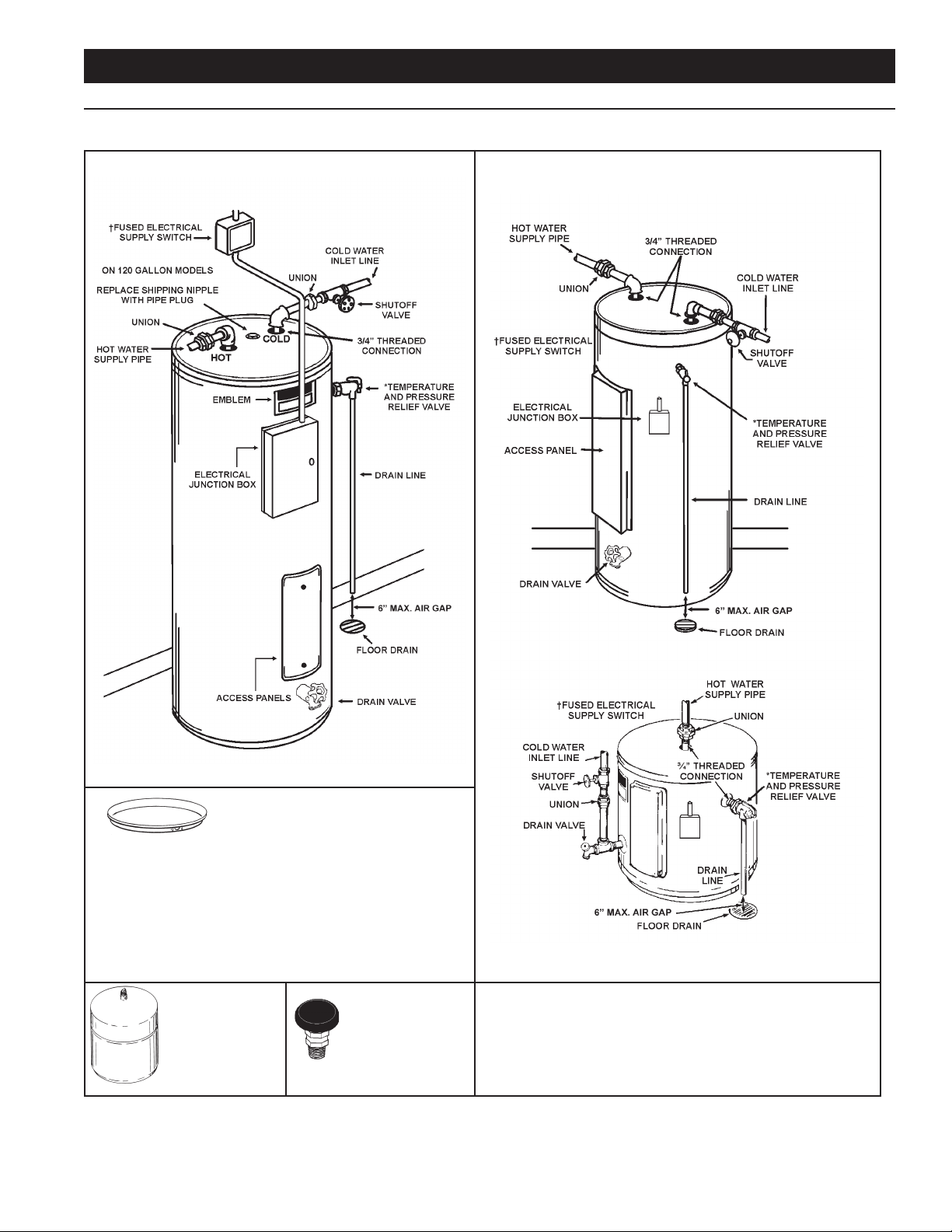
This page shows typical water heater installations by model designations.
Lowboy 30/40/50 & All Tall Water Heaters Single-Element Water Heater
Install suitable drain pans under water heaters to
prevent damage due to leakage. Refer to water heater
location on page 8.
Install thermal expansion
tank if check valve or
pressure reducing valve
is used in supply line.
† OVER CURRENT PROTECTION MUST BE SUPPLIED IN WATER HEATER CIRCUIT.
Install vacuum relief in cold
water inlet line as required
by local codes.
CONSULT LOCAL CODE OR CURRENT EDITION OF NEC FOR PROPER INSTALLATION.
* INSTALL IN ACCORDANCE WITH ALL LOCAL CODES.
Figure 4. Typical Water Heater Installations
7
Page 8
LOCATING THE NEW WATER HEATER
FACTS TO CONSIDER ABOUT THE LOCATION
CAUTION
Property Damage Hazard
All water heaters eventually leak.
•
Do not install without adequate drainage.
•
The water heater should be located as close as possible to/or
centralized to the water piping system. The water heater should
be located in an area not subject to freezing temperatures.
The water heater should be located in an area where leakage
of the tank or connections will not result in damage to the area
adjacent to the heater or to lower oors of the structure.
When such locations cannot be avoided, a suitable drain pan
should be installed under the heater.
Such pans should be at least two inches deep, have a minimum
length and width of at least two inches greater than the diameter
of the heater and should be piped to an adequate drain.
Drain pans suitable for these water heaters are available from
your distributor, dealer or manufacturer listed on the rating plate.
Water heater life depends upon water quality, water pressure
and the environment in which the water heater is installed. Water
heaters are sometimes installed in locations where leakage may
result in property damage, even with the use of a drain pan piped
to a drain. However, unanticipated damage can be reduced or
prevented by a leak detector or water shut-off device used in
conjunction with a piped drain pan. These devices are available
from some plumbing supply wholesalers and retailers, and detect
and react to leakage in various ways:
• Sensors mounted in the drain pan that trigger an alarm or
turn off the incoming water to the water heater when leakage
is detected.
• Sensors mounted in the drain pan that turn off the water
supply to the entire home when water is detected in the
drain pan.
• Water supply shut-off devices that activate based on the
water pressure differential between the cold water and how
water pipes connected to the water heater.
• Devices that will turn off the gas supply to a gas water heater
while at the same time shutting off its water supply.
CLEARANCES
A minimum clearance of 4” must be allowed for access to
replaceable parts such as thermostats, drain valve and relief
valve.
Adequate clearance for servicing this water heater should be
considered before installation, such as changing the anodes, etc.
FLOOD WARNING
IF THE HEATER BECOMES IMMERSED IN WATER UP TO
OR ABOVE THE LEVEL OF THE BOTTOM OF THE ELEMENT
DOORS, THE HEATER SHOULD BE EXAMINED BY A
COMPETENT SERVICE PERSON BEFORE IT IS PLACED IN
OPERATION.
8
Page 9
INSTALLATION
Water temperature over 125°F (52°C)
can cause severe burns instantly
resulting in severe injury or death.
Children, the elderly and the
physically or mentally disabled are at
highest risk for scald injury.
Feel water before bathing or
showering.
Temperature limiting devices such as
mixing valves must be installed
when required by codes and to
ensure safe temperatures at fixtures.
Toxic Chemical Hazard
•
Do not connect to non-potable water system.
REQUIRED ABILITY
Installation and service of this water heater requires ability
equivalent to that of a qualied installer or service agency (page
2) in the eld involved. Plumbing and electrical work is required.
GENERAL
The installation must conform with these instructions and the
local code authority having jurisdiction and the requirements of
the power company. In the absence of local codes, the installation
must comply with the latest editions of the National Electrical
Code, NFPA 70 or the Canadian Electrical Code CSA C22.1.
The National Electrical Code may be ordered from: National Fire
Protection Association, 1 Batterymarch Park, Quincy, MA 02269.
The Canadian Electrical Code is available from the Canadian
Standards Association, 8501 East Pleasant Valley Road,
Cleveland, OH 44131.
Do NOT test electrical system before heater is lled with water,
follow the START UP procedure in the OPERATION section of
this manual.
The principal components of the heater are identied in the
Features and Components illustrations on 7.
Table 3. Time/Temperature to Burn
Time for Permanent
Water Temperature
°F (°C)
110 (43) (normal shower temp.)
116 (47) (pain threshold)
116 (47) 35 minutes 45 minutes
122 (50) 1 minute 5 minutes
131 (55) 5 seconds 25 seconds
140 (60) 2 seconds 5 seconds
149 (65) 1 second 2 seconds
154 (68) instantaneous 1 second
(U.S. Government Memorandum, C.P.S.C., Peter L. Armstrong, Sept. 15, 1978)
COLD
WATER
INLET
Time for 1st Degree Burn
(Less Severe Burns)
HOT WATER
OUTLET
TEMPERED WATER
OUTLET
CHECK
VALV E
12” TO 15”
(30-38 cm)
CHECK
MIXING
VALV E
VALV E
Burns
2nd & 3rd Degree
(Most Severe Burns)
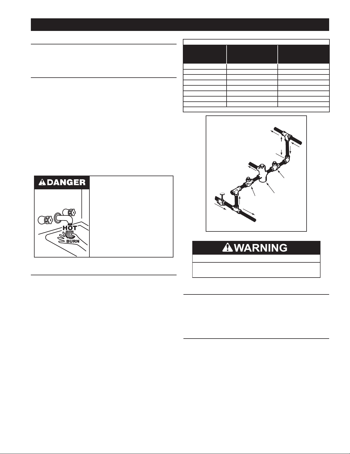
MIXING VALVE USAGE:
Water heaters are intended to produce hot water. Water heated
to a temperature which will satisfy space heating, clothes
washing, dish washing, cleaning, and other sanitizing needs
can scald and permanently injure you upon contact.
Some people are more likely to be permanently injured by
hot water than others. These include the elderly, children, the
inrm, and the physically/mentally disabled. Table 3 shows the
approximate time-to-burn relationship for normal adult skin. If
anyone using hot water provided by the water heater being
installed ts into one of these groups or if there is a local code
or state law requiring a certain water temperature at the point
of use, then special precautions must be taken.
In addition to using the lowest possible temperature setting
that satises the demand of the application a Mixing Valve
should be installed at the water heater (see Figure 5) or at the
hot water taps to further reduce system water temperature.
Mixing valves are available at plumbing supply stores. Consult
a Qualied Installer or Service Agency. Follow the mixing
valve manufacturer’s instructions for installation of the valves.
TO TANK
INLET
Figure 5. Mixing Valve
CONTAMINATED WATER
This water heater shall not be connected to any heating system(s)
or component(s) used with a non-potable water heating appliance.
Toxic chemicals, such as those used for boiler treatment shall not
be introduced into this system.
CIRCULATING PUMP
A circulating pump is used when a system requires a circulating
loop or there is a storage tank used in conjunction with the water
heater. See Water Piping Diagrams on page NN for installation
location of circulating pumps.
Install in accordance with the current edition of the National
Electrical Code, NFPA 70 or the Canadian Electrical Code, CSA
C22.1.
All bronze or stainless steel circulating pumps are recommended
for used with commercial water heaters.
Some circulating pumps are manufactured with sealed bearings
and do not require further lubrication. Some circulating pumps must
be periodically oiled. See the pump manufacturer’s instructions
for lubrication requirements.
9
Page 10
INSULATION BLANKETS
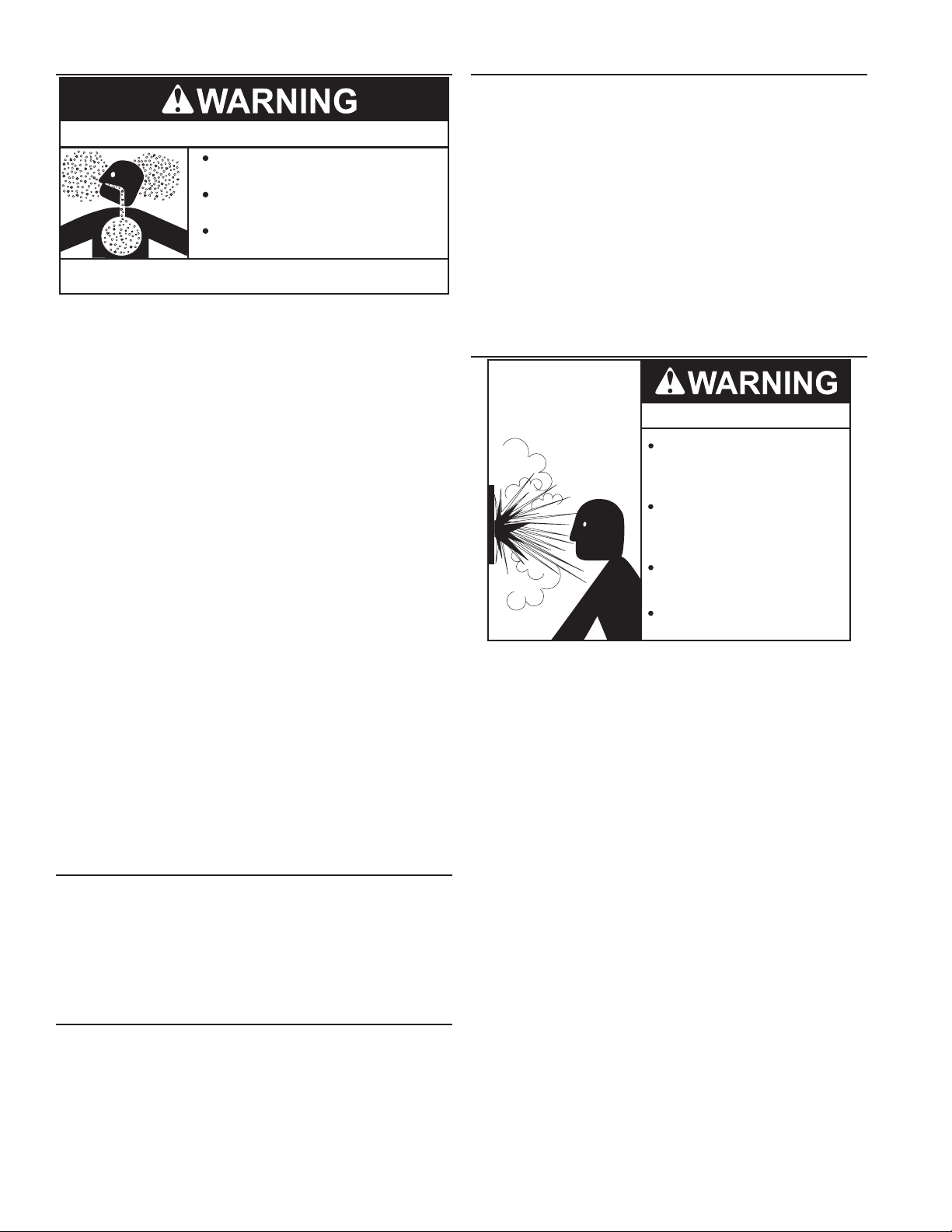
Breathing Hazard - Carbon Monoxide Gas
Do not obstruct water heater air intake
with insulating blanket.
Gas and carbon monoxide detectors
are available.
Install water heater in accordance with
the instruction manual.
Breathing carbon monoxide can cause brain damage or
death. Always read and understand instruction manual.
Insulation blankets are available to the general public for
external use on gas water heaters but are not necessary with
these products. The purpose of an insulation blanket is to
reduce the standby-heat loss encountered with storage tank
heaters. The water heaters covered by this manual meet or
exceed the Energy Policy Act standards with respect to
insulation and standby-heat loss requirements, making an
insulation blanket unnecessary.
THERMAL EXPANSION
As water is heated, it expands (thermal expansion). In a closed
system, the volume of water will grow when it is heated. As the
volume of water grows, there is a corresponding increase in
water pressure, due to thermal expansion. Thermal expansion
can cause premature tank failure (leakage). This type of failure
is not covered under the limited warranty. Thermal expansion
can also cause intermittent temperature-pressure relief valve
operation, water discharged from the valve due to excessive
pressure build up. This condition is not covered under the
limited warranty. The temperature-pressure relief valve is not
intended for the constant relief of thermal expansion.
A properly-sized thermal-expansion tank must be installed on
all closed systems to control the harmful effects of thermal
expansion. Contact a local plumbing service agency to have
a thermal-expansion tank installed.
TEMPERATURE-PRESSURE RELIEF VALVE
Explosion Hazard
If you choose to apply an insulation blanket to this heater,
you should follow these instructions. See the Features
and Components section of this manual for identification
of components mentioned below. Failure to follow these
instructions can restrict the air flow required for proper
combustion, potentially resulting in re, asphyxiation, serious
personal injury, or death.
• DO NOT apply insulation to the top of the water heater, as
this will interfere with safe operation of the draft hood.
• DO NOT cover the gas valve, thermostat, or the temperature-
pressure relief valve.
• DO NOT allow insulation to come within two inches (5 cm)
of the burners, to prevent blockage of combustion air ow to
the burners.
• DO NOT allow insulation to come within nine inches (23 cm)
of oor, (within two inches (5 cm) of bottom cover) to prevent
blockage of combustion air ow to the burners.
• DO NOT cover the instruction manual. Keep it on the side of
the water heater or nearby for future reference.
• DO obtain new warning and instruction labels from the
manufacturer for placement on the blanket, directly over the
existing labels.
• DO inspect the insulation blanket frequently to make certain it
does not sag, thereby obstructing combustion air ow.
HARD WATER
Where hard water conditions exist, water softening or the
threshold-type of water treatment is recommended. This will
protect the dishwashers, coffee urns, water heaters, water
piping, and other equipment.
See the Maintenance section in this manual for sediment and
lime scale removal procedures.
CLOSED WATER SYSTEMS
Water-supply systems can, because of code requirements or
such conditions as high line pressure, among others, have
installed devices such as pressure-reducing valves, check
valves, and back-ow preventers. Devices such as these cause
the water system to be a closed system.
Temperature-Pressure Relief Valve
must comply with ANSI Z21.22CSA 4.4 and ASME code.
Properly sized temperaturepressure relief valve must be
installed in opening provided.
Can result in overheating and
excessive tank pressure.
Can cause serious injury or death.
This water heater is provided with a properly rated/sized
and certied combination temperature-pressure relief valve
(T&P valve) by the manufacturer. The valve is certied by a
nationally-recognized testing laboratory that maintains periodic
inspection of the production of listed equipment and of materials
as meeting the requirements for Relief Valves for Hot Water
Supply Systems, ANSI Z21.22 • CSA 4.4, and the code
requirements of ASME.
If replaced, the new T&P valve must meet the requirements
of local codes, but not less than a combination temperaturepressure relief valve rated/sized and certied as indicated in
the above paragraph. The new valve must be marked with a
maximum set pressure not to exceed the marked hydrostatic
working pressure of the water heater (150 psi = 1,035 kPa) and
a discharge capacity not less than the water heater Btu/hr or kW
input rate, as shown on the water heater’s model rating label.
Note: In addition to the factory installed temperature-pressure
relief valve on the water heater, each remote-storage
tank that is installed and piped to a water heating
appliance must also have its own properly-sized, rated,
and approved temperature-pressure relief valve installed.
Call the toll-free technical-support phone number listed
on the back cover of this manual for technical assistance
in sizing a temperature-pressure relief valve for remote
storage tanks.
For safe operation of the water heater, the temperaturepressure relief valve must not be removed from its designated
opening, nor plugged. The temperature-pressure relief
valve must be installed directly into the tting of the water
heater designed for the relief valve. Install discharge piping
so that any discharge exits the pipe six inches (15.2 cm)
above an adequate oor drain, or external to the building. In
cold climates, it is recommended that it be terminated at an
10
Page 11
adequate drain inside the building. Be certain that no contact is
CAUTION
made with any live electrical part. The discharge opening must
not be blocked or reduced in size under any circumstances.
Excessive length over 30 feet (9.14 m) or use of more than
four elbows can cause restriction and reduce the discharge
capacity of the valve.
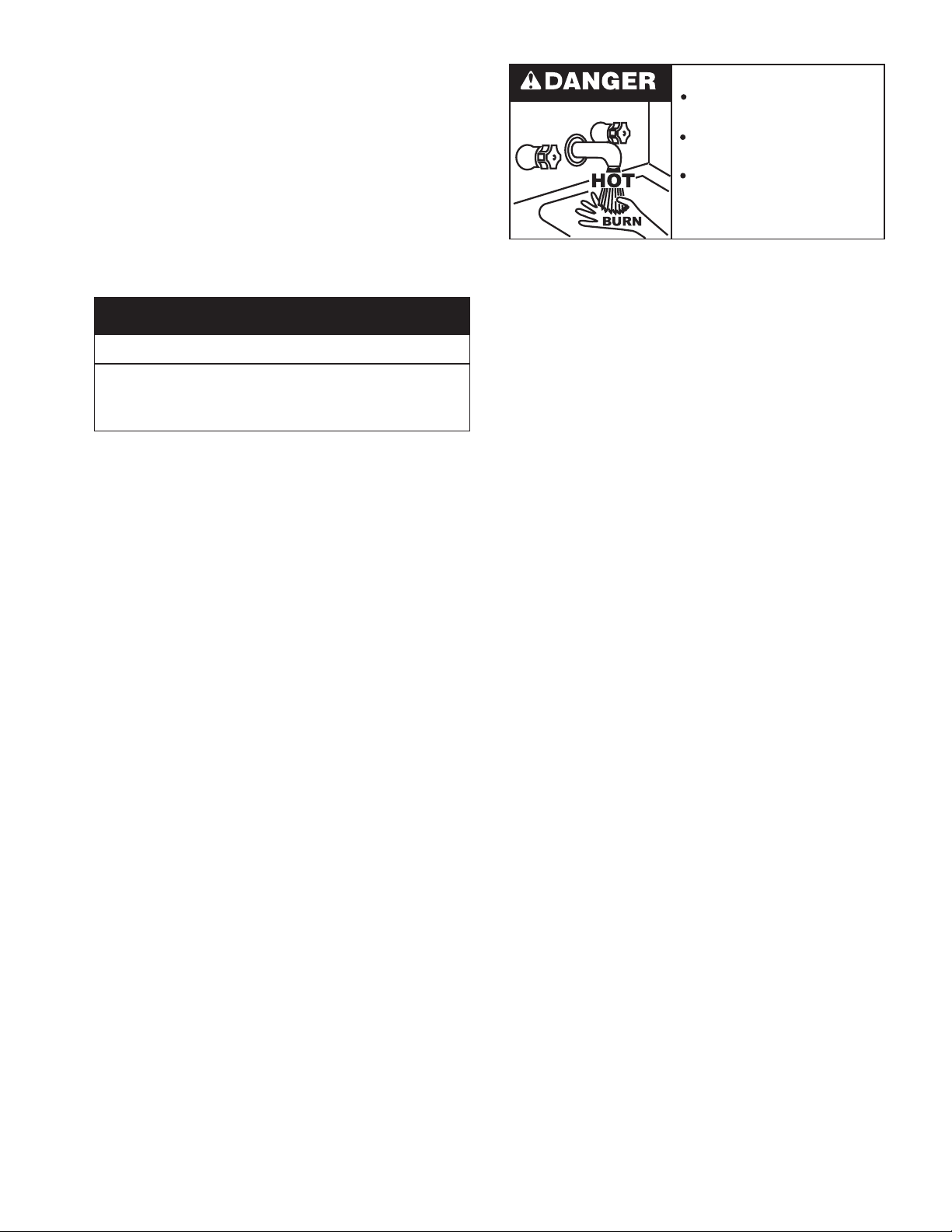
Burn hazard.
Hot water discharge.
No valve or other obstruction is to be placed between the
temperature-pressure relief valve and the tank. Do not
connect discharge piping directly to the drain unless an air
gap of six inches (15.2 cm) is provided. To prevent bodily
injury, hazard to life, or property damage, the relief valve
must be allowed to discharge water in adequate quantities if
circumstances demand. If the discharge pipe is not connected
to a drain or other suitable means, the water ow could cause
property damage.
Water Damage Hazard
Temperature-Pressure Relief Valve discharge
•
pipe must terminate at adequate drain.
T&P VALVE DISCHARGE PIPE REQUIREMENTS:
• Shall not be smaller in size than the outlet-pipe size of the
valve, or have any reducing couplings or other restrictions.
• Shall not be plugged or blocked.
• Shall not be exposed to freezing temperatures.
• Shall be of material listed for hot water distribution.
• Shall be installed so as to allow complete drainage of both
the temperature-pressure relief valve and the discharge pipe.
• Must terminate a maximum of six inches (15.2 cm) above a
oor drain or external to the building. In cold climates, it is
recommended that the discharge pipe be terminated at an
adequate drain inside the building.
• Shall not have any valve or other obstruction between the
relief valve and the drain.
Keep clear of TemperaturePressure Relief Valve
discharge outlet.
The temperature-pressure relief valve must be manually
operated at least twice a year. Caution should be taken to
ensure that (1) no one is in front of or around the outlet of
the temperature-pressure relief valve discharge line, and (2)
the water that is manually discharged does not cause any
bodily injury or property damage because the water may be
extremely hot. If after manually operating the valve, it fails to
completely reset and continues to release water, immediately
close the cold-water inlet to the water heater, follow the draining
instructions in this manual, and replace the temperaturepressure relief valve with a properly rated/sized new one.
Note: The purpose of a temperature-pressure relief valve is
to prevent excessive temperatures and pressures in
the storage tank. The T&P valve is not intended for the
constant relief of thermal expansion. A properly-sized
thermal-expansion tank must be installed on all closed
systems to control thermal expansion. See Closed Water
Systems and Thermal Expansion on page 10.
11
Page 12
ELECTRICAL
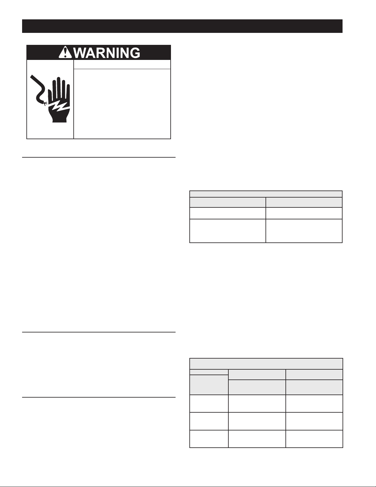
Turn off power at the branch circuit
breaker serving the water heater
before performing any service.
Electrical Shock Hazard
•
Label all wires prior to disconnecting
when performing service. Wiring errors
can cause improper and dangerous
operation.
•
Verify proper operation after servicing.
•
Failure to follow these instructions can
result in personal injury or death.
•
GENERAL
The installation must conform with these instructions and the
local code authority having jurisdiction and the requirements of
the power company. In the absence of local codes, the installation
must comply with the current editions of the National Electrical
Code, NFPA 70 or the Canadian Electrical Code CSA C22.1.
An electrical ground is required to reduce risk of electrical shock
or possible electrocution. The water heater should be connected
to a separate grounded branch circuit with over-current protection
and disconnect switch. The water heater should be grounded in
accordance with national and local codes.
Voltage applied to the heater should not vary more than +5%
to -10% of the model and rating plate marking for satisfactory
operation.
DO NOT ENERGIZE THE BRANCH CIRCUIT FOR ANY
REASON BEFORE THE HEATER TANK IS FILLED WITH
WATER. DOING SO WILL CAUSE THE HEATING ELEMENTS
TO BURN OUT AND VOID WARRANTY.
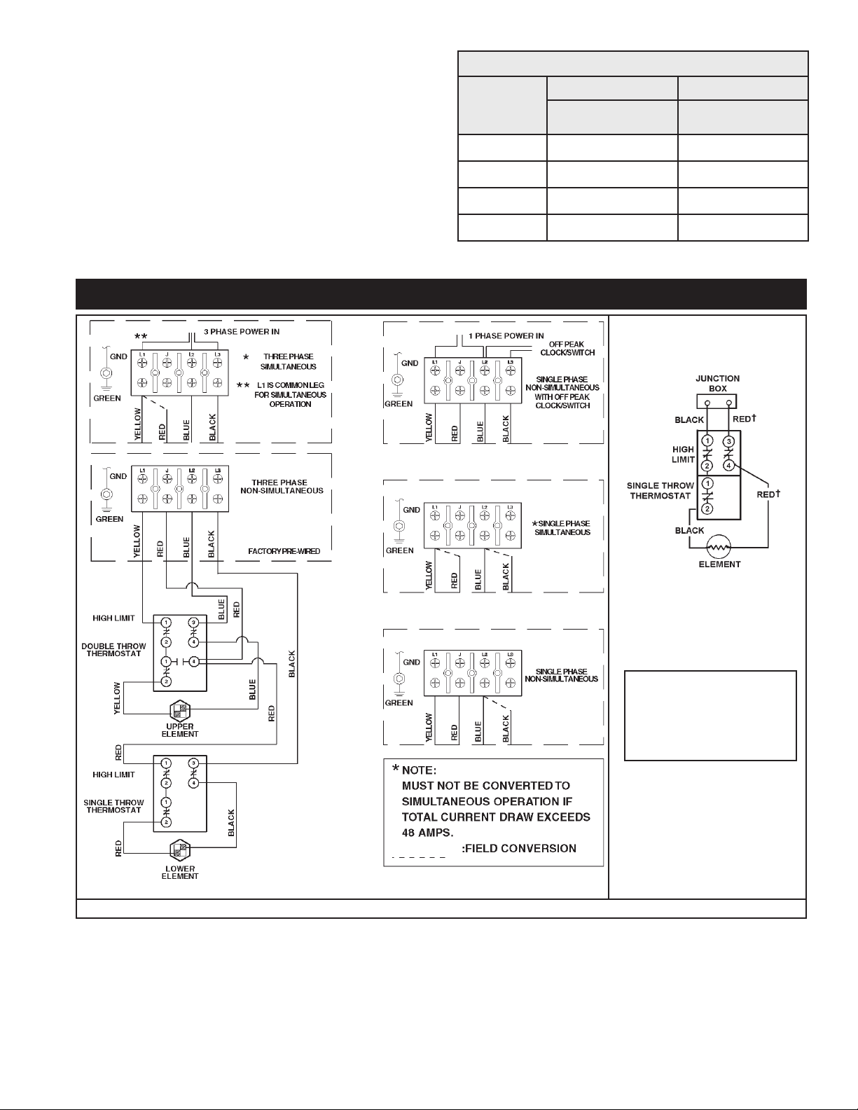
Element connection is for non-simultaneous operation. This
means only one element at a time operates. The Wiring
Diagrams (page 13) show the heater may be eld converted
to simultaneous element operation by moving the red wire on “J”
terminal to L1. It is then possible for both elements to operate at
once as determined by the thermostats. Regardless of element
connection the heater operates in an “unbalanced” fashion.
The heater may be eld converted to single-phase operation by
moving the wire on L3 of the terminal block to L2. L3 is not used,
see Wiring Diagrams (page 13).
The heater, now in single-phase non-simultaneous operation,
may be eld-converted to single phase simultaneous operation by
moving the red wire on terminal “J” to L1. See Wiring Diagrams
(page 13).
This is an example of calculating heater amperage for both types
of element operation. From this, the branch circuit conductor and
over-current protection sizing can be established.
The example is of a three-phase 240 volt unit with two, 6 kw
elements. The notations are for units eld converted to singlephase. Check the heater model and rating plate for actual
specications and substitute those values in the following.
Table 4. Calculating Heater Amperage
Non-simultaneous:
(as factory wired)
3000 : 240 = 12.5 amps*
3000 : 240 = 12.5 amps*
12.5 x 1.73 = 21.6 amps
Simultaneous:
(Field conversion)
Note: As a single-phase
Note: As a single-phase
non-simultaneous unit.
simultaneous unit the
total is: 12.5 x 2 = 25
amps
The rating of the over-current protection should be computed on
the basis of 125 percent of the total connected load amperage.
Where the standard ratings and settings do not correspond
with this computation, the next higher standard rating or setting
should be selected.
The factory wiring is attached to a terminal block within the
external junction box unit. The branch circuit is connected to
the terminal block within this junction box. The water heater
should be connected to a separate, grounded, branch circuit with
overcurrent protection and disconnect switch. The water heater
should be grounded in accordance with national and local codes.
BRANCH CIRCUIT
The branch circuit wire size should be established through
reference to the current edition of NFPA-70, the National
Electrical Code or other locally approved source in conjunction
with the heater amperage rating. For convenience, portions of
the wire size tables from the Code are reproduced here. The
branch circuit should be sized at 125 percent of the heater rating
and further increase wire size as necessary to compensate for
voltage drop in long runs.
CALCULATING AMPERAGE/OVER-CURRENT PROTECTION
The heaters come from the factory in two congurations:
1. Two wire C-2 circuit for single element heater equipped with
a high limit control, single phase power input.
2. Four wire A-8 circuit for dual element heater equipped with two
high limit controls, single phase or three phase power input.
The heater with dual elements is factory wired for connection to
a three wire, three-phase delta branch circuit, non-simultaneous
operation. In addition a ground conductor is required.
PORTION OF TABLE 310-16 (NFPA-70) FOLLOWS:
Allowable Ampacities of Insulated Copper Conductors. Not more
than three conductors in Raceway or Cable or Direct Burial (Based
on Ambient Temperature of 30° C, 86° F).
These ampacities relate only to conductors described in Table 31013 in Code.
For ambient temperatures over 30° C (86° F), see Correction Factors,
Note 13 in Code.
For ambient temperatures over 30° C (86° F), see Correction Factors,
Note 13 in Code.
Table 5. Temperature Rating of Conductor
Size 60°C
AMG
MCM
18
16
14
12
10
8
6
4
3
12
See Table 310-13 in Code
(140°F)
Types:
RUW, (14-2), T, TW, UF
- - -
- - -
15
20
30
40
55
70
80
RH, RHW, RUH, (14-2),
THW, THWN, XHHW, USE
75°C
(167°F)
Types:
- - -
- - -
15
20
30
45
65
85
100
Page 13
PORTION OF TABLE 310-18 FOLLOWS:
Allowable Ampacities of Insulated Aluminum and Copper -Clad
Aluminum Conductors.
Not more than three conductors in Raceway or Cable or Direct Burial
(Based on Ambient Temperature of 30° C, 86° F. These ampacities
relate only to conductors described in Table 310-13 in Code.
For ambient temperatures over 30° C (86° F), see Correction Factors,
Note 13 in Code.
WIRING DIAGRAMS
Table 6. Temperature Rating of Conductor
See Table 310-13 in Code
60°C
AMG
MCM
12
10
8
6
4
3
2
1
(140°F)
Types:
RUW, (12-2), T, TW, UF
15
25
30
40
55
65
75
85
RH, RHW, RUH, (12-2),
THW, THWN, XHHW, USE
C-2 Circuit For Compact
6/10/15/20 Heaters Equipped
With High-Limit Control
75°C
(167°F)
Types:
15
25
40
50
65
75
90
100
A-8 Circuit For Dual Element Heater
Figure 6. Wiring Diagram
______ FACTORY WIRED
---------- FIELD WIRING
† WHITE FOR 120V & 277V
13
Page 14
OPERATION
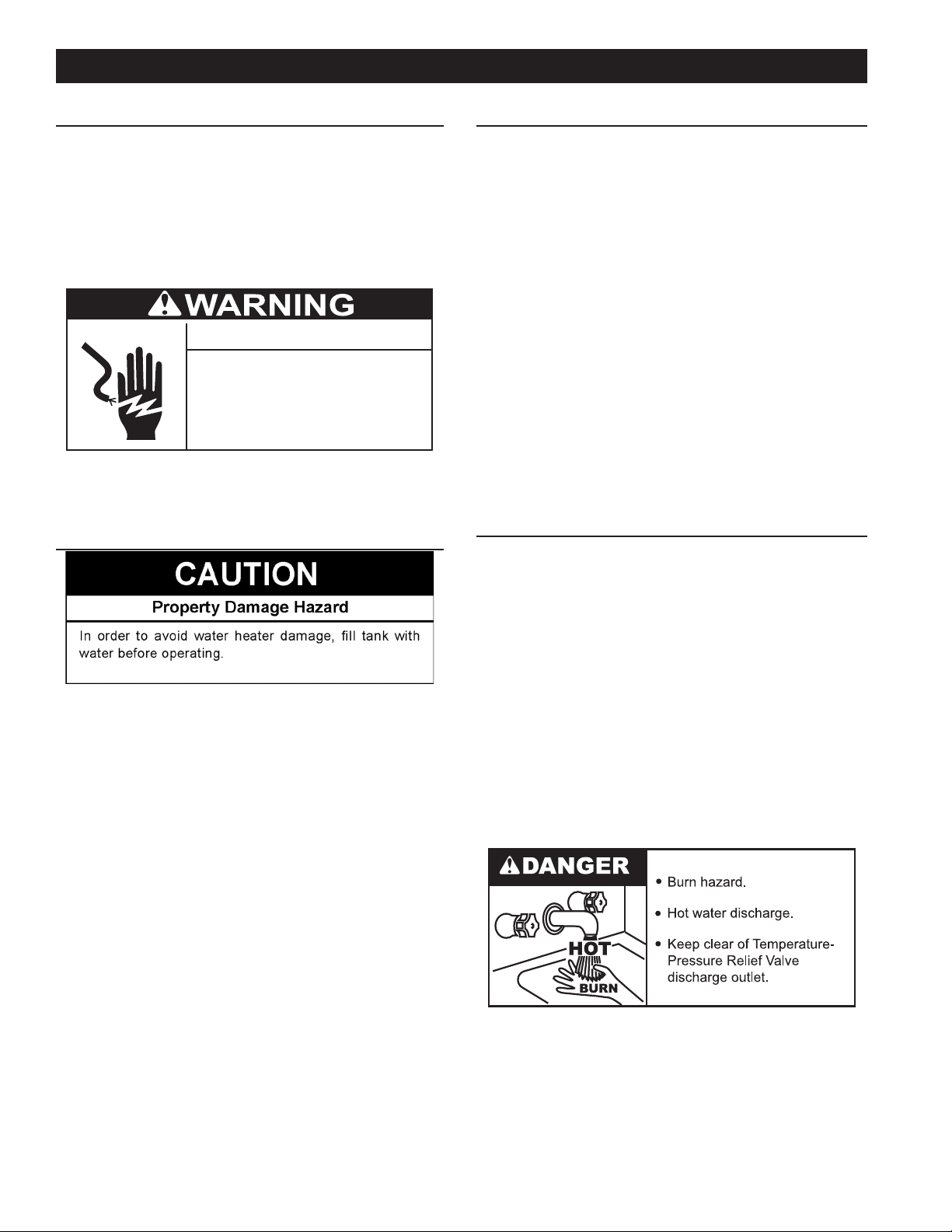
Full power is present whenever the
cabinent door is opend even with the
pilot switch turned off.
Electrical Shock Hazard
GENERAL
Refer to Features and Components (page 7) for the location
of components mentioned in the instructions that follow.
NEVER turn on power to the water heater without being certain
the water heater is lled with water and a temperature and
pressure relief valve is installed in the relief valve opening.
DO NOT TEST ELECTRICAL SYSTEM BEFORE HEATER IS
FILLED WITH WATER. FOLLOW FILLING AND START-UP
INSTRUCTIONS IN OPERATION SECTION.
Temperature control and contactor operation should be checked
by allowing heater to come up to temperature and shut off
automatically. Use care as the electrical circuits are energized.
FILLING THE WATER HEATER
INITIAL START UP
The following checks should be made by the installer when the
heater is placed into operation for the rst time.
1. Turn off the electrical disconnect switch.
2. Open the front panel or top access cover, check all water and
electrical connections for tightness. Also check connections
on top and or sides of heater. Repair water leaks and tighten
electrical connections as necessary.
3. Press the red manual reset button on each Thermostat/ECO
combination control. See Figure 7, Figure 8, Figure 9, or Figure
10 (page 9).
4. Turn on the electrical disconnect switch.
5. Observe the operation of the electrical components during
the rst heating cycle. Use care as the electrical circuits are
energized.
6. Close the front panel or top access cover.
Temperature control and contactor operation should be checked
by allowing heater to come up to temperature and shut off
automatically. Use care as the electrical circuits are energized.
DRAINING THE WATER HEATER
The water heater must be drained if it is to be shut down and
exposed to freezing temperatures. Maintenance and service
procedures may also require draining the heater.
1. Turn off the electrical disconnect switch.
2. Close the water heater drain valve.
3. Open a nearby hot water faucet to permit the air in the system
to escape.
4. Fully open the cold water inlet pipe valve allowing the heater
and piping to be lled.
5. Close the hot water faucet as water starts to ow. The heater is
now ready for STARTUP and TEMPERATURE REGULATION.
1. Turn off the electrical disconnect switch.
2. Open a hot water valve until the water is cool, then close the
supply water inlet valve to heater.
3. Attach hose to outlet opening of drain valve and direct end
to drain.
4. Open a nearby hot water faucet and the heater drain valve.
5. If the heater is being drained for an extended shutdown, it is
suggested the drain valve be left open during this period. The
hose may be removed.
Follow FILLING instructions when restoring hot water service.
14
Page 15
TEMPERATURE REGULATION
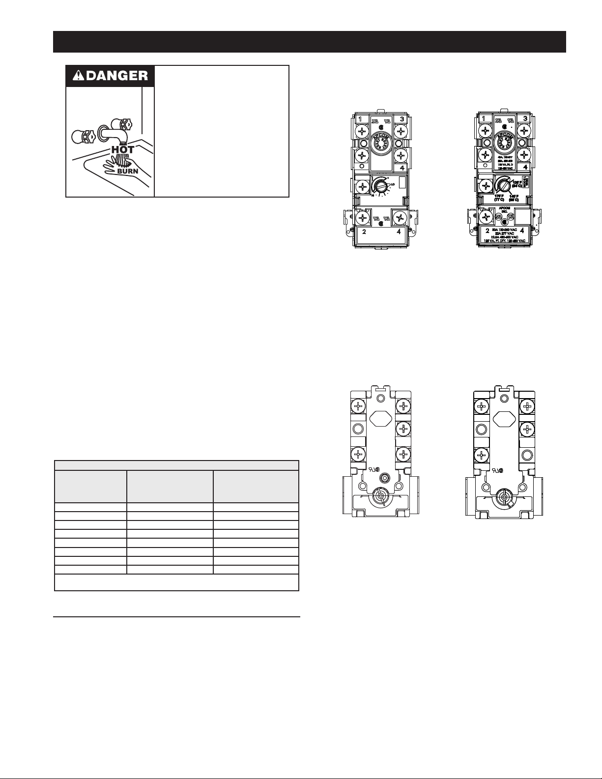
Water temperature over 125°F (52°C)
can cause severe burns instantly
resulting in severe injury or death.
Children, the elderly and the
physically or mentally disabled are at
highest risk for scald injury.
Feel water before bathing or
showering.
Temperature limiting devices such as
mixing valves must be installed
when required by codes and to
ensure safe temperatures at fixtures.
THE WATER HEATER IS EQUIPPED WITH AN ADJUSTABLE
THERMOSTAT TO CONTROL WATER TEMPERATURE. HOT
WATER AT TEMPERATURES DESIRED FOR AUTOMATIC
DISHWASHER AND LAUNDRY USE CAN CAUSE SCALDS
RESULTING IN SERIOUS PERSONAL INJURY AND/OR
DEATH. THE TEMPERATURE AT WHICH INJURY OCCURS
VARIES WITH THE PERSON’S AGE AND TIME OF EXPOSURE.
THE SLOWER RESPONSE TIME OF CHILDREN , AGED OR
DISABLED PERSONS INCREASES THE HAZARD TO THEM.
NEVER ALLOW SMALL CHILDREN TO USE A HOT WATER TAP,
OR TO DRAW THEIR OWN BATH WATER. NEVER LEAVE A
CHILD OR DISABLED PERSON UNATTENDED IN A BATHTUB
OR SHOWER.
It is recommended that lower water temperatures be used to avoid
the risk of scalding. It is further recommended, in all cases, that the
water temperature thermostats (see Table 7) be set for the lowest
temperature which satises your hot water needs. This will also
provide the most energy efcient operation of the water heater.
approximately 130°F (54°C) to 170°F (77°C) (See Figure 8).
These thermostats are set from the factory at approximately the
140°F (60°C) setting. The over temperature device (ECO high
limit) attached to each thermostat has a manual reset.
40A 120-277 VAC
25A.480-600 VAC
125VA.PT.DTY.
120-480 VAC
MODEL
WH10C
MED
APCOM
INC
30A 120-250 VAC
22A 277 VAC
12.5A 480-600VAC
125 VA.PT.DTY. 120-480 VAC
Figure 7. A-8 Circuit
Thermostat with
Three Set Points
Figure 8. C-2 Circuit
Thermostat Adjustment Range
THERMODISC THERMOSTATS
A-8 circuit thermodisc thermostats are adjustable from
approximately 120°F (49°C) (lowest setting) to 181°F (83°C)
(highest setting) (See Figure 9). The C-2 circuit thermostat is
adjustable from approximately 110°F (43°C) to 170°F (77°C)
(See Figure 10). These thermostats are set from the factory at
approximately the 140°F (60°C) setting. The over temperature
device (ECO high limit) attached to each thermostat has a
manual reset.
Table 7 shows the approximate time-to-burn relationship for
normal adult skin. The thermostats on your water heater have
a linear relationship between degrees of angular rotation and
the corresponding change in temperature. Thus rotating the
temperature adjustment indicator 30 angular degrees will result
in a 10 degree Fahrenheit change in water temperature.
Table 7. BURN TIME AT VARIOUS TEMPERATURES
Water
Temperature
°F (°C)
110 (43) (normal shower temp.)
116 (47) (pain threshold)
116 (47) 35 minutes 45 minutes
122 (50) 1 minute 5 minutes
131 (55) 5 seconds 25 seconds
140 (60) 2 seconds 5 seconds
149 (65) 1 second 2 seconds
154 (68) instantaneous 1 second
(U.S. Government Memorandum, C.P.S.C., Peter L. Armstrong, Sept. 15,
1978)
Time for
1st Degree Burn
(Less Severe Burns)
Time for
Permanent Burns
2nd & 3rd Degree
(Most Severe Burns)
TEMPERATURE ADJUSTMENT
The water heater is supplied with thermostats that may come from
different manufactures and have different temperature indications
as described below.
APCOM THERMOSTATS
A-8 Circuit thermostats have three designated set points;
LO, MED and HI. (See Figure 7).The approximate equivalent
temperatures for these three settings are: LO = 140°F (60°C),
MED = 160°F (71°C) and HI = 181°F (83°C). These thermostats
are set from the factory at the LO 140°F (60°C) setting. The over
temperature device (ECO high limit) attached to each thermostat
has a manual reset. The C-2 circuit thermostat is adjustable from
L1 L3
RESET
RESET
L4
L2
T1
T2 T4
89T
THERM O DISC
181°F
120°F
140°F
Figure 9. A-8 Thermodisc
Thermostat
Figure 10. C-2 Thermodisc
L1 L3
RESET
L2
T1
T2 T4
THERM-O-DISC
170°F
140°F
Thermostat
RESET
L4
110°F
Note: It is not necessary to adjust the upper thermostat for a
dual element unit. However, if it is adjusted above the
factory set point 140°F (60°C) it is recommended that it
not be set higher than the lower thermostat setting.
To change the temperature setting:
1. DANGER: Turn off the heater electrical supply. Do not attempt
to adjust thermostat with power on.
2. Open the junction box door (for upper thermostat of dual
element water heater only) and/or remove the (lower)
thermostat access panel. Do not remove the plastic personnel
protectors covering the thermostats. The thermostat is factory
pre-set at 140°F (60°C).
3. Using a at tip screwdriver, rotate the adjusting knob to the
desired temperature setting.
4. Replace the covers and access panels, and turn on heater
electrical supply.
15
Page 16
DISCHARGE PIPE
TEMPERATURE-PRESSURE
RELIEF VALV E
MAINTENANCE
GENERAL
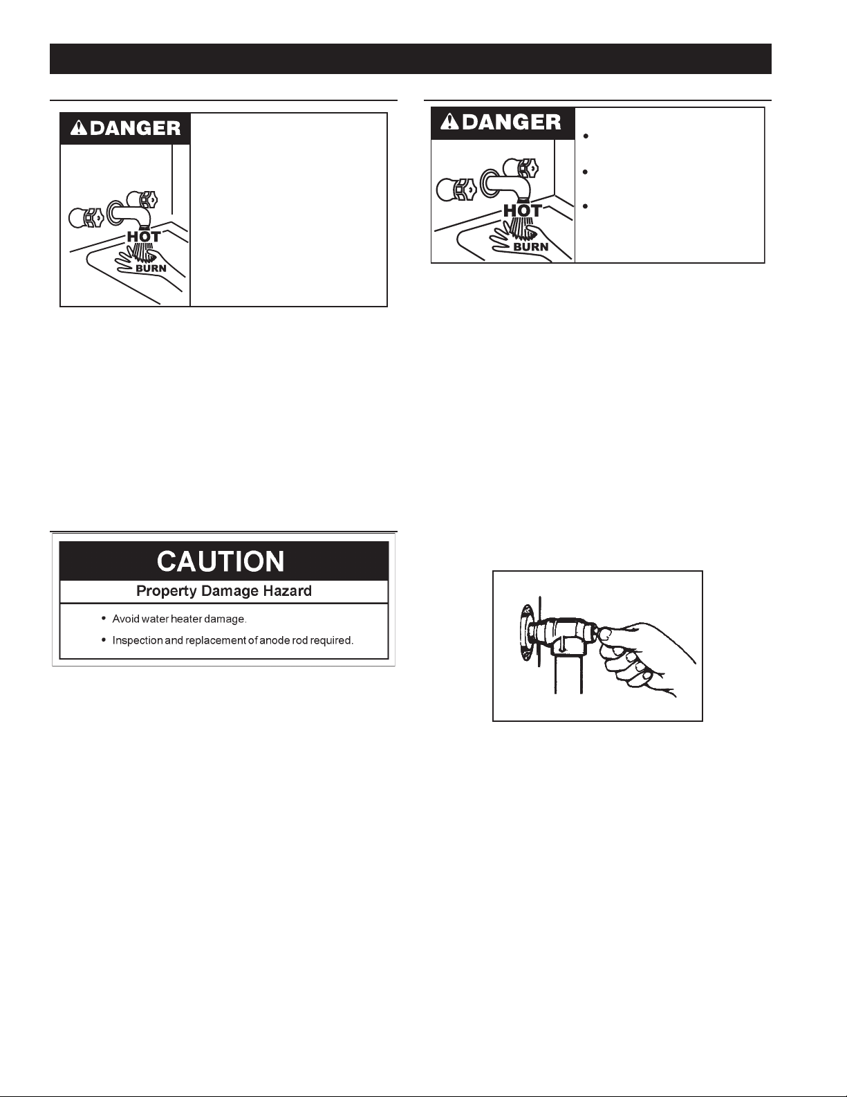
Water temperature over 125°F (52°C)
can cause severe burns instantly
resulting in severe injury or death.
Children, the elderly and the
physically or mentally disabled are at
highest risk for scald injury.
Feel water before bathing or
showering.
Temperature limiting devices such as
mixing valves must be installed
when required by codes and to
ensure safe temperatures at fixtures.
Periodically the drain valve should be opened and the water
allowed to run until it ows clean. This will help to prevent
sediment buildup in the tank bottom.
Periodically check the temperature and pressure relief valve to
ensure that it is in operating condition. Lift the lever at the top
of the valve several times until the valve seats properly and
operates freely.
Water heater maintenance includes periodic tank ushing and
cleaning, and removal of lime scale from the heating element.
The heater tank is equipped with an anode rod to aid in corrosion
control.
ANODE ROD MAINTENANCE
TEMPERATURE-PRESSURE RELIEF VALVE TEST
Burn hazard.
Hot water discharge.
Keep clear of TemperaturePressure Relief Valve
discharge outlet.
It is recommended that the temperature-pressure relief valve
should be checked to ensure that it is in operating condition
every six months.
When checking the temperature-pressure relief valve
operation, make sure that (1) no one is in front of or around the
outlet of the temperature-pressure relief valve discharge line,
and (2) that the water discharge does not cause any property
damage, because the water could be extremely hot. Use care
when operating valve because the valve could be hot.
To check the relief valve, lift the lever at the end of the valve
several times. See Figure 11. The valve should seat properly
and operate freely.
If after manually operating the valve, it fails to completely
reset and continues to release water, immediately close the
cold water inlet to the water heater and drain the water heater.
See Draining the Water Heater on page 9. Replace the
temperature-pressure relief valve with a properly rated/sized
new one. See Temperature-Pressure Relief Valve on page
10 for instructions on replacement.
The anode rod is used to protect the tank from corrosion. Most
hot water tanks are equipped with an anode rod. The submerged
rod sacrices itself to protect the tank. Instead of corroding tank,
water ions attack and eat away the anode rod. This does not
affect water’s taste or color. The rod must be maintained to keep
tank in operating condition.
Anode deterioration depends on water conductivity, not
necessarily water condition. A corroded or pitted anode rod
indicates high water conductivity and should be checked and/
or replaced more often than an anode rod that appears to be
intact. Replacement of a depleted anode rod can extend the life of
your water heater. Inspection should be conducted by a qualied
technician, and at a minimum should be checked annually after
the warranty period.
Articially softened water is exceedingly corrosive because the
process substitutes sodium ions for magnesium and calcium ions.
The use of a water softener may decrease the life of the water
heater tank.
The anode rod should be inspected after a maximum of three
years and annually thereafter until the condition of the anode rod
dictates its replacement.
Articially softened water requires the anode rod to be inspected
annually.
Figure 11. Temperature-Pressure Relief Valve Test
If the temperature-pressure relief valve on the water heater
weeps or discharges periodically, this may be due to thermal
expansion.
Note: Excessive water pressure is the most common cause
of temperature-pressure relief valve leakage. Excessive
water-system pressure is most often caused by thermal
expansion in a closed system. See Closed Water
Systems and Thermal Expansion on page 9. The
temperature-pressure relief valve is not intended for the
constant relief of thermal expansion.
Temperature-pressure relief valve leakage due to pressure
build up in a closed system that does not have a thermalexpansion tank installed is not covered under the limited
warranty. Thermal-expansion tanks must be installed on all
closed water systems.
DO NOT PLUG THE TEMPERATURE-PRESSURE RELIEF
VALVE OPENING. THIS CAN CAUSE PROPERTY
DAMAGE, SERIOUS INJURY OR DEATH.
16
Page 17
TROUBLESHOOTING CHECKLIST
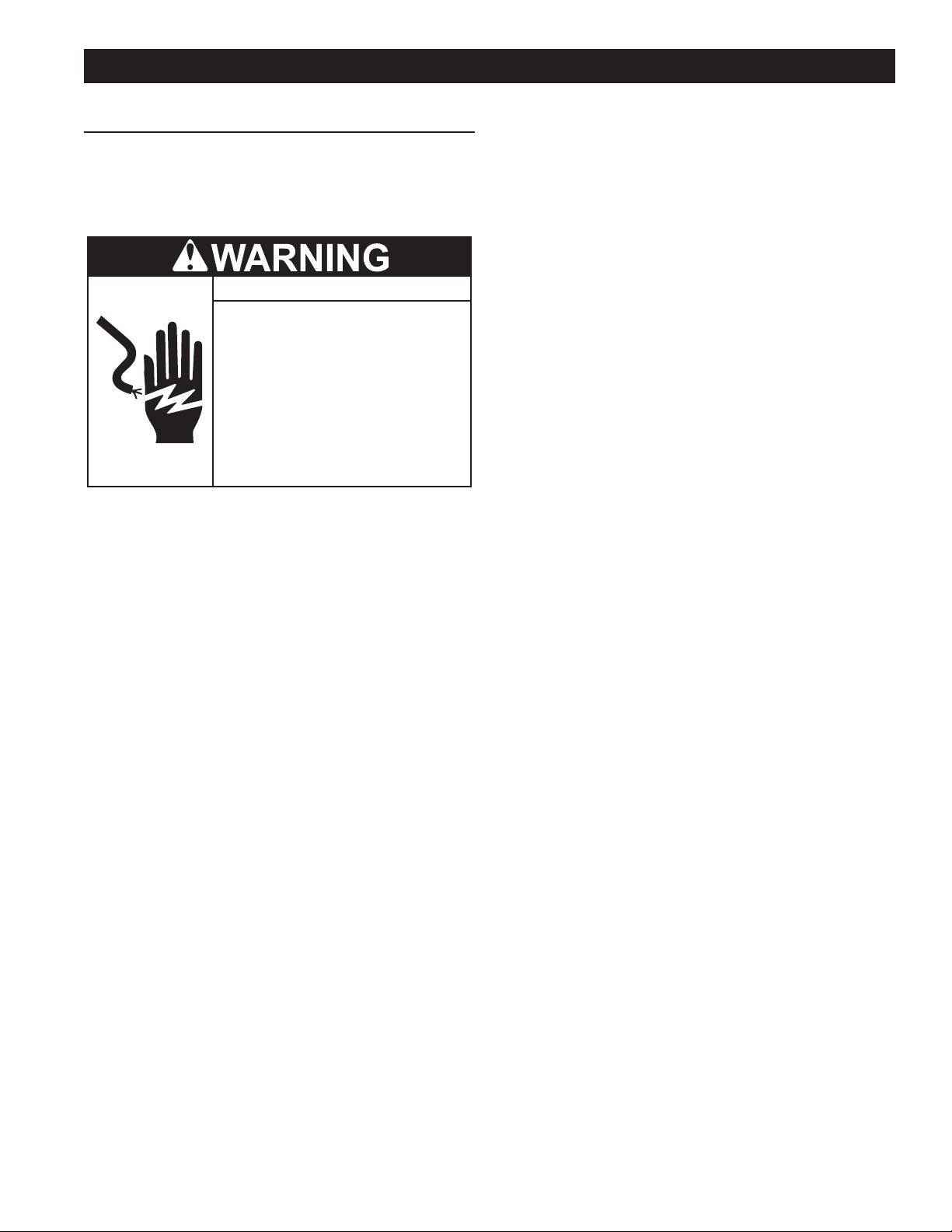
Turn off power at the branch circuit
breaker serving the water heater
before performing any service.
Electrical Shock Hazard
•
Label all wires prior to disconnecting
when performing service. Wiring errors
can cause improper and dangerous
operation.
•
Verify proper operation after servicing.
•
Failure to follow these instructions can
result in personal injury or death.
•
CHECKLIST
Before calling for service, check the following points to see if the
cause of trouble can be identied and corrected.
Reviewing this checklist may eliminate the need of a service call
and quickly restore hot water service. See Figure 4 on page 7
in this manual to identify and locate water heater components.
NOT ENOUGH OR NO HOT WATER
1. Be certain the electrical disconnect switch serving the water
heater is in the ON position.
ABNORMAL SOUNDS
1. Sediment or lime scale accumulations on the elements causes
sizzling and hissing noises when the heater is operating.
• The sounds are normal, however, the tank bottom and
elements should be cleaned. See the Maintenance
section (page 16) of this manual.
WATER LEAKAGE IS SUSPECTED
Refer to Leakage Checkpoint on the following page 18.
1. Check to see if the heater drain valve is tightly closed.
2. If the outlet of the relief valve is leaking it may represent:
• Excessive water temperature.
• Faulty relief valve.
• Excessive water pressure.
3. Excessive water pressure is the most common cause of relief
valve leakage. It is often caused by a “closed system”. See
“Closed Water Systems” and “Thermal Expansion” in the
Installation section of this manual for more information.
4. Examine the area around the element for gasket leakage.
• Tighten the elements or, if necessary, replace the gas-
kets.
IF YOU CANNOT IDENTIFY OR CORRECT THE SOURCE OF MALFUNCTION
1. Turn the power supply to the water heater off.
2. Check the fuses.
• The electrical disconnect switch usually contains fuses.
3. If the water was excessively hot, and is now cold, the high limit
switch may have activated.
• See the Temperature Regulation section of this manual
for more information on how to reset the ECO high limit
controls.
4. The capacity of the heater may have been exceeded by a large
demand for hot water.
• Large demands require a recovery period to restore
water temperature.
5. Cooler incoming water temperature will lengthen the time
required to heat water to the desired temperature.
6. Look for hot water leakage.
7. Sediment or pipe scale may be affecting water heater operation.
2. Close the supply water inlet valve to the heater.
3. Contact a Qualied Service Agency in your area. Call the toll
free phone number on the water heater label for assistance in
locating a service agency in your area.
REPLACEMENT PARTS
For replacement parts please contact the company it was
purchased from or direct from the manufacturer listed on the
rating plate on the water heater.
17
Page 18
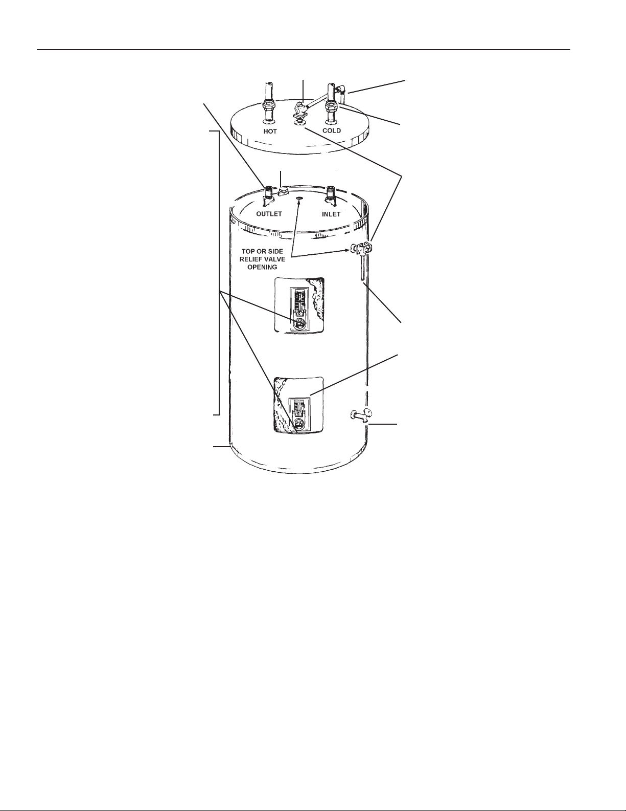
LEAKAGE CHECKPOINTS
Instructions: Use this illustration as a guide when checking for sources of water leakage.
Where possible remove or lift top cover to
examine threads of ttings installed into tank
for evidence of leakage. Correct tting leaks
as necessary.
Relief Valve
To Open Drain
Water leaks at the elements may be due to:
1. Defective element which leaks at
terminals or thru flange. Replace
element*.
2. Loose element/gasket leak:
(a) Screw-in type: tighten with 1-1/2”
socket wrench. If leak continues,
remove element*, discard gasket
and clean thread areas.Apply
nonhardening Permatex Number
2 to thread areas, install new
gasket and screw element into
tting until it seats. Tighten 1/2 to
3/4 turn with wrench.
(b) Flange type: tighten screw with
wrench. If leak continues remove
element* and discard gasket.
Clean gasket seating areas
and re-install element with new
gasket. A new element may be
required where threads have
become rusted or damaged,
preventing tightening.
All water which appears at the water
heater bottom or on the surrounding oor
may be caused by condensation, loose
connections or relief valve operation
and leakage. Do not replace the water
heater until full inspection of all potential
leak points is made and corrective steps
taken to stop the leak. Leakage from other
appliances, water lines or ground (see
page 17) should also be suspected until
proven otherwise.
Condensation and dripping may appear
on pipes when cold water temperature is
low. Pipe tting may be leaking.
Anode Rod (Some Models)
Relief valve operation and leakage
may be due to water expansion during
heating cycle or foreign material on seat
of valve. If the valve is not piped to an
open drain the released water could be
mistaken for a leaking heater. To check
where threaded material between jacket
opening and swab spud area. Remove
valve* if indicated and repair with pipe
joint compound.
To Open Drain
Water on the side of the tank may
be condensation due to the panel or
insulation not being in place.
Drain valve leakage could be from the
valve itself.* To check for leakage where
threaded portion enters tank, insert Q-tip
or similar absorbent material between
jacket opening and valve to swab spud
area. Remove valve* if leak is indicated
and repair with pipe joint compound.
*Contact your dealer as it is necessary to
shut off electricity and drain tank to perform
procedure.
Figure 12. Leakage Test Points
18
Page 19

NOTES
19
Page 20

Copyright © 2018. All rights reserved.
20
 Loading...