

Page 1

User Guide
PIM Master™
Passive Intermodulation Analyzer
with Site Master™ Cable &
Antenna Analyzer (331) and
2-Port Options (703)
MW82119B
Anritsu Company
490 Jarvis Drive
Morgan Hill, CA 95037-2809
USA
http://www.anritsu.com
Part Number: 10580-00400
Published: February 2021
Copyright 2014, 2021 Anritsu Company
Revision: N
Page 2

Page 3

Table of Contents
Chapter 1—General Information
1-1 Introduction . . . . . . . . . . . . . . . . . . . . . . . . . . . . . . . . . . . . . . . . . . . . . . . . . 1-1
Related Documentation . . . . . . . . . . . . . . . . . . . . . . . . . . . . . . . . . . . . . 1-1
Document Conventions . . . . . . . . . . . . . . . . . . . . . . . . . . . . . . . . . . . . . 1-2
Contacting Anritsu for Sales and Service . . . . . . . . . . . . . . . . . . . . . . . 1-2
1-2 Instrument Description . . . . . . . . . . . . . . . . . . . . . . . . . . . . . . . . . . . . . . . . 1-3
PIM Master Options. . . . . . . . . . . . . . . . . . . . . . . . . . . . . . . . . . . . . . . . 1-3
1-3 Instrument Care and Preventive Maintenance . . . . . . . . . . . . . . . . . . . . . . 1-4
Connector Care . . . . . . . . . . . . . . . . . . . . . . . . . . . . . . . . . . . . . . . . . . . 1-4
Connecting Procedure. . . . . . . . . . . . . . . . . . . . . . . . . . . . . . . . . . . . . . 1-4
Test Cable from PIM Master to DUT . . . . . . . . . . . . . . . . . . . . . . . . . . . 1-5
Disconnecting Procedure . . . . . . . . . . . . . . . . . . . . . . . . . . . . . . . . . . . 1-5
Connector Saver . . . . . . . . . . . . . . . . . . . . . . . . . . . . . . . . . . . . . . . . . . 1-5
ESD Caution . . . . . . . . . . . . . . . . . . . . . . . . . . . . . . . . . . . . . . . . . . . . . 1-6
Battery Information . . . . . . . . . . . . . . . . . . . . . . . . . . . . . . . . . . . . . . . . 1-6
PIM Master Firmware Update . . . . . . . . . . . . . . . . . . . . . . . . . . . . . . . . 1-7
1-4 Calibration Requirements . . . . . . . . . . . . . . . . . . . . . . . . . . . . . . . . . . . . . . 1-7
1-5 Wireless Remote Control . . . . . . . . . . . . . . . . . . . . . . . . . . . . . . . . . . . . . . 1-7
Chapter 2—PIM Master Overview
2-1 Introduction . . . . . . . . . . . . . . . . . . . . . . . . . . . . . . . . . . . . . . . . . . . . . . . . . 2-1
2-2 Turning On the PIM Master for the First Time . . . . . . . . . . . . . . . . . . . . . . 2-1
Calibration Due Date . . . . . . . . . . . . . . . . . . . . . . . . . . . . . . . . . . . . . . . 2-2
Calibration Reminder. . . . . . . . . . . . . . . . . . . . . . . . . . . . . . . . . . . . . . . 2-3
2-3 Front Panel Overview . . . . . . . . . . . . . . . . . . . . . . . . . . . . . . . . . . . . . . . . . 2-3
MW82119B PIM Master Front Panel. . . . . . . . . . . . . . . . . . . . . . . . . . . 2-4
2-4 Front Panel Keys . . . . . . . . . . . . . . . . . . . . . . . . . . . . . . . . . . . . . . . . . . . . 2-5
2-5 Top Connector Panel . . . . . . . . . . . . . . . . . . . . . . . . . . . . . . . . . . . . . . . . . 2-8
2-6 Top Connector Panel -- Option 703 . . . . . . . . . . . . . . . . . . . . . . . . . . . . . 2-10
2-7 Side Panel Connectors . . . . . . . . . . . . . . . . . . . . . . . . . . . . . . . . . . . . . . . 2-11
2-8 Measurement Display Overview . . . . . . . . . . . . . . . . . . . . . . . . . . . . . . . . 2-13
Front Panel Display Areas . . . . . . . . . . . . . . . . . . . . . . . . . . . . . . . . . 2-13
Main Menu Keys . . . . . . . . . . . . . . . . . . . . . . . . . . . . . . . . . . . . . . . . . 2-14
Submenu Keys . . . . . . . . . . . . . . . . . . . . . . . . . . . . . . . . . . . . . . . . . . 2-14
2-9 Secondary Function Menus . . . . . . . . . . . . . . . . . . . . . . . . . . . . . . . . . . . 2-19
2-10 Mode Selector Menu. . . . . . . . . . . . . . . . . . . . . . . . . . . . . . . . . . . . . . . . . 2-20
2-11 Menu Key . . . . . . . . . . . . . . . . . . . . . . . . . . . . . . . . . . . . . . . . . . . . . . . . . 2-21
MW82119B UG PN: 10580-00400 Rev. N Contents-1
Page 4

Table of Contents (Continued)
2-12 Touch Screen . . . . . . . . . . . . . . . . . . . . . . . . . . . . . . . . . . . . . . . . . . . . . . 2-24
Graphical User Interface (GUI) . . . . . . . . . . . . . . . . . . . . . . . . . . . . . . 2-24
2-13 Touch Screen Calibration . . . . . . . . . . . . . . . . . . . . . . . . . . . . . . . . . . . . . 2-25
Calibrate Touch Screen Shortcut. . . . . . . . . . . . . . . . . . . . . . . . . . . . . 2-25
Arrow Navigation . . . . . . . . . . . . . . . . . . . . . . . . . . . . . . . . . . . . . . . . . 2-25
2-14 Parameter Setting . . . . . . . . . . . . . . . . . . . . . . . . . . . . . . . . . . . . . . . . . . . 2-26
2-15 Symbols and Indicators. . . . . . . . . . . . . . . . . . . . . . . . . . . . . . . . . . . . . . . 2-27
2-16 Soft Carrying Case . . . . . . . . . . . . . . . . . . . . . . . . . . . . . . . . . . . . . . . . . . 2-28
2-17 Tilt Bail Stand . . . . . . . . . . . . . . . . . . . . . . . . . . . . . . . . . . . . . . . . . . . . . . 2-31
Chapter 3—Quick Start Guide
3-1 Introduction . . . . . . . . . . . . . . . . . . . . . . . . . . . . . . . . . . . . . . . . . . . . . . . . . 3-1
3-2 Measurement Mode Selection . . . . . . . . . . . . . . . . . . . . . . . . . . . . . . . . . . 3-2
3-3 Cable & Antenna Analyzer Measurements (Option 331) . . . . . . . . . . . . . . 3-3
Select the Measurement Type. . . . . . . . . . . . . . . . . . . . . . . . . . . . . . . . 3-3
Set the Frequency . . . . . . . . . . . . . . . . . . . . . . . . . . . . . . . . . . . . . . . . . 3-3
Set the Amplitude . . . . . . . . . . . . . . . . . . . . . . . . . . . . . . . . . . . . . . . . . 3-4
Turn on Markers . . . . . . . . . . . . . . . . . . . . . . . . . . . . . . . . . . . . . . . . . . 3-4
Single Limit Line . . . . . . . . . . . . . . . . . . . . . . . . . . . . . . . . . . . . . . . . . . 3-5
DTF Setup . . . . . . . . . . . . . . . . . . . . . . . . . . . . . . . . . . . . . . . . . . . . . . . 3-6
Calibrate with OSL Calibration. . . . . . . . . . . . . . . . . . . . . . . . . . . . . . . . 3-7
3-4 Passive Intermodulation (PIM) Measurements . . . . . . . . . . . . . . . . . . . . . . 3-8
Preparing for PIM Measurements . . . . . . . . . . . . . . . . . . . . . . . . . . . . . 3-8
Calibrating the PIM Analyzer . . . . . . . . . . . . . . . . . . . . . . . . . . . . . . . . 3-10
Verifying Residual PIM . . . . . . . . . . . . . . . . . . . . . . . . . . . . . . . . . . . . 3-13
Verifying the PIM Standard . . . . . . . . . . . . . . . . . . . . . . . . . . . . . . . . . 3-13
Verifying the PIM Test Cable . . . . . . . . . . . . . . . . . . . . . . . . . . . . . . . . 3-15
Checking for External Interference . . . . . . . . . . . . . . . . . . . . . . . . . . . 3-15
Making PIM Measurements . . . . . . . . . . . . . . . . . . . . . . . . . . . . . . . . . 3-16
Measurement Types . . . . . . . . . . . . . . . . . . . . . . . . . . . . . . . . . . . . . . 3-16
Adding a Limit Line . . . . . . . . . . . . . . . . . . . . . . . . . . . . . . . . . . . . . . . 3-17
3-5 Setting Up Markers . . . . . . . . . . . . . . . . . . . . . . . . . . . . . . . . . . . . . . . . . . 3-18
3-6 Saving Measurements . . . . . . . . . . . . . . . . . . . . . . . . . . . . . . . . . . . . . . . 3-18
Chapter 4—File Management
4-1 Introduction . . . . . . . . . . . . . . . . . . . . . . . . . . . . . . . . . . . . . . . . . . . . . . . . . 4-1
4-2 Managing Files . . . . . . . . . . . . . . . . . . . . . . . . . . . . . . . . . . . . . . . . . . . . . . 4-2
File Types . . . . . . . . . . . . . . . . . . . . . . . . . . . . . . . . . . . . . . . . . . . . . . . 4-2
Contents-2 PN: 10580-00400 Rev. N MW82119B UG
Page 5

Table of Contents (Continued)
4-3 File Management . . . . . . . . . . . . . . . . . . . . . . . . . . . . . . . . . . . . . . . . . . . . 4-3
Saving Files . . . . . . . . . . . . . . . . . . . . . . . . . . . . . . . . . . . . . . . . . . . . . . 4-3
Save Dialog Box . . . . . . . . . . . . . . . . . . . . . . . . . . . . . . . . . . . . . . . . . . 4-4
Quick Name Keys . . . . . . . . . . . . . . . . . . . . . . . . . . . . . . . . . . . . . . . . . 4-5
Recalling Files . . . . . . . . . . . . . . . . . . . . . . . . . . . . . . . . . . . . . . . . . . . . 4-6
Recall Dialog Box . . . . . . . . . . . . . . . . . . . . . . . . . . . . . . . . . . . . . . . . . 4-7
Copying Files. . . . . . . . . . . . . . . . . . . . . . . . . . . . . . . . . . . . . . . . . . . . . 4-8
Deleting Files. . . . . . . . . . . . . . . . . . . . . . . . . . . . . . . . . . . . . . . . . . . . 4-10
Delete Dialog Box . . . . . . . . . . . . . . . . . . . . . . . . . . . . . . . . . . . . . . . . 4-10
4-4 File Menu Overview . . . . . . . . . . . . . . . . . . . . . . . . . . . . . . . . . . . . . . . . . 4-11
4-5 File Menu . . . . . . . . . . . . . . . . . . . . . . . . . . . . . . . . . . . . . . . . . . . . . . . . . 4-12
4-6 Save Menu . . . . . . . . . . . . . . . . . . . . . . . . . . . . . . . . . . . . . . . . . . . . . . . . 4-13
4-7 Save Location Menu . . . . . . . . . . . . . . . . . . . . . . . . . . . . . . . . . . . . . . . . . 4-14
Select Save Location Dialog Box . . . . . . . . . . . . . . . . . . . . . . . . . . . . 4-15
Create Directory Dialog Box . . . . . . . . . . . . . . . . . . . . . . . . . . . . . . . . 4-16
4-8 Recall Menu . . . . . . . . . . . . . . . . . . . . . . . . . . . . . . . . . . . . . . . . . . . . . . . 4-17
Recall Dialog Box . . . . . . . . . . . . . . . . . . . . . . . . . . . . . . . . . . . . . . . . 4-18
4-9 Copy Menu . . . . . . . . . . . . . . . . . . . . . . . . . . . . . . . . . . . . . . . . . . . . . . . . 4-19
Copy Dialog Box . . . . . . . . . . . . . . . . . . . . . . . . . . . . . . . . . . . . . . . . . 4-20
4-10 Delete Menu . . . . . . . . . . . . . . . . . . . . . . . . . . . . . . . . . . . . . . . . . . . . . . . 4-21
Chapter 5—System Operation
5-1 Introduction . . . . . . . . . . . . . . . . . . . . . . . . . . . . . . . . . . . . . . . . . . . . . . . . . 5-1
5-2 System Menu Overview . . . . . . . . . . . . . . . . . . . . . . . . . . . . . . . . . . . . . . . 5-1
System Menu Map. . . . . . . . . . . . . . . . . . . . . . . . . . . . . . . . . . . . . . . . . 5-2
5-3 System Menu . . . . . . . . . . . . . . . . . . . . . . . . . . . . . . . . . . . . . . . . . . . . . . . 5-3
System Options Menu . . . . . . . . . . . . . . . . . . . . . . . . . . . . . . . . . . . . . . 5-4
Display Settings Menu. . . . . . . . . . . . . . . . . . . . . . . . . . . . . . . . . . . . . . 5-5
Brightness Settings Menu . . . . . . . . . . . . . . . . . . . . . . . . . . . . . . . . . . . 5-6
Reset Menu . . . . . . . . . . . . . . . . . . . . . . . . . . . . . . . . . . . . . . . . . . . . . . 5-7
5-4 Preset Menu . . . . . . . . . . . . . . . . . . . . . . . . . . . . . . . . . . . . . . . . . . . . . . . . 5-8
5-5 Self Test . . . . . . . . . . . . . . . . . . . . . . . . . . . . . . . . . . . . . . . . . . . . . . . . . . . 5-8
Chapter 6—GPS (Option 31)
6-1 Introduction . . . . . . . . . . . . . . . . . . . . . . . . . . . . . . . . . . . . . . . . . . . . . . . . . 6-1
6-2 Setting Up GPS (Option 31) . . . . . . . . . . . . . . . . . . . . . . . . . . . . . . . . . . . . 6-1
Activating the GPS Feature . . . . . . . . . . . . . . . . . . . . . . . . . . . . . . . . . . 6-1
MW82119B UG PN: 10580-00400 Rev. N Contents-3
Page 6

Table of Contents (Continued)
6-3 GPS Menu . . . . . . . . . . . . . . . . . . . . . . . . . . . . . . . . . . . . . . . . . . . . . . . . . 6-3
GPS Info . . . . . . . . . . . . . . . . . . . . . . . . . . . . . . . . . . . . . . . . . . . . . . . . 6-4
Chapter 7—Anritsu Tool Box with LST
7-1 Introduction . . . . . . . . . . . . . . . . . . . . . . . . . . . . . . . . . . . . . . . . . . . . . . . . . 7-1
7-2 Anritsu Tool Box . . . . . . . . . . . . . . . . . . . . . . . . . . . . . . . . . . . . . . . . . . . . . 7-1
7-3 Install the Software . . . . . . . . . . . . . . . . . . . . . . . . . . . . . . . . . . . . . . . . . . . 7-1
7-4 Line Sweep Tools . . . . . . . . . . . . . . . . . . . . . . . . . . . . . . . . . . . . . . . . . . . . 7-3
Why use Line Sweep Tools? . . . . . . . . . . . . . . . . . . . . . . . . . . . . . . . . . 7-3
Line Sweep Tools Features . . . . . . . . . . . . . . . . . . . . . . . . . . . . . . . . . . 7-4
Using Line Sweep Tools . . . . . . . . . . . . . . . . . . . . . . . . . . . . . . . . . . . . 7-4
Markers and Limit Lines. . . . . . . . . . . . . . . . . . . . . . . . . . . . . . . . . . . . . 7-5
Marker Presets . . . . . . . . . . . . . . . . . . . . . . . . . . . . . . . . . . . . . . . . . . . 7-5
Naming Grid. . . . . . . . . . . . . . . . . . . . . . . . . . . . . . . . . . . . . . . . . . . . . . 7-6
Report Generator. . . . . . . . . . . . . . . . . . . . . . . . . . . . . . . . . . . . . . . . . . 7-7
Appendix A—Other Documents
A-1 Introduction . . . . . . . . . . . . . . . . . . . . . . . . . . . . . . . . . . . . . . . . . . . . . . . . .A-1
PIM Master Options . . . . . . . . . . . . . . . . . . . . . . . . . . . . . . . . . . . . . . . . A-1
Related Documents . . . . . . . . . . . . . . . . . . . . . . . . . . . . . . . . . . . . . . . . A-1
Appendix B—PIM Carrier Bands
B-1 Introduction . . . . . . . . . . . . . . . . . . . . . . . . . . . . . . . . . . . . . . . . . . . . . . . . .B-1
B-2 PIM Master Carrier Bands . . . . . . . . . . . . . . . . . . . . . . . . . . . . . . . . . . . . .B-1
Appendix C—Wireless Remote Control
C-1 Introduction. . . . . . . . . . . . . . . . . . . . . . . . . . . . . . . . . . . . . . . . . . . . . . . . .C-1
C-2 Portable Router for Wireless Access . . . . . . . . . . . . . . . . . . . . . . . . . . . . .C-1
C-3 Configuring the PIM Master for Wireless Browser Control . . . . . . . . . . . . .C-2
Contents-4 PN: 10580-00400 Rev. N MW82119B UG
Page 7

Table of Contents (Continued)
C-4 Using a ZyXEL MWR102 Travel Router. . . . . . . . . . . . . . . . . . . . . . . . . . . C-2
Connecting the Router to the PIM Master . . . . . . . . . . . . . . . . . . . . . . . C-3
Configuring PIM Master for use with Router . . . . . . . . . . . . . . . . . . . . . C-4
C-5 Remote Control via a Browser . . . . . . . . . . . . . . . . . . . . . . . . . . . . . . . . . . C-6
Screen Capture . . . . . . . . . . . . . . . . . . . . . . . . . . . . . . . . . . . . . . . . . . . C-7
List of Files . . . . . . . . . . . . . . . . . . . . . . . . . . . . . . . . . . . . . . . . . . . . . . C-7
Using Anritsu Line Sweep Tools . . . . . . . . . . . . . . . . . . . . . . . . . . . . . . C-8
Saving Measurements. . . . . . . . . . . . . . . . . . . . . . . . . . . . . . . . . . . . . .C-9
Password Protection . . . . . . . . . . . . . . . . . . . . . . . . . . . . . . . . . . . . . . C-11
Instrument Name . . . . . . . . . . . . . . . . . . . . . . . . . . . . . . . . . . . . . . . . . C-12
Appendix D—Instrument Messages and Errors
D-1 Error Messages: Stop Current Measurements . . . . . . . . . . . . . . . . . . . . . .D-1
D-2 PIM Analyzer Warning Messages. . . . . . . . . . . . . . . . . . . . . . . . . . . . . . . .D-1
D-3 Operation Error Messages . . . . . . . . . . . . . . . . . . . . . . . . . . . . . . . . . . . . . D-3
Appendix E—Instrument Care
E-1 Introduction . . . . . . . . . . . . . . . . . . . . . . . . . . . . . . . . . . . . . . . . . . . . . . . . . E-1
Appendix Overview . . . . . . . . . . . . . . . . . . . . . . . . . . . . . . . . . . . . . . . . E-1
E-2 Preventive Maintenance . . . . . . . . . . . . . . . . . . . . . . . . . . . . . . . . . . . . . . E-1
E-3 Battery Care . . . . . . . . . . . . . . . . . . . . . . . . . . . . . . . . . . . . . . . . . . . . . . . . E-2
E-4 Battery Replacement . . . . . . . . . . . . . . . . . . . . . . . . . . . . . . . . . . . . . . . . . E-3
E-5 PIM Master Firmware Update . . . . . . . . . . . . . . . . . . . . . . . . . . . . . . . . . . E-6
Determining the Firmware Version . . . . . . . . . . . . . . . . . . . . . . . . . . . . E-6
Downloading the Firmware . . . . . . . . . . . . . . . . . . . . . . . . . . . . . . . . . . E-6
Updating with a USB Memory Device . . . . . . . . . . . . . . . . . . . . . . . . . . E-7
E-6 Adding Options with a License File. . . . . . . . . . . . . . . . . . . . . . . . . . . . . . . E-9
Appendix F—LAN and DHCP
F-1 Introduction . . . . . . . . . . . . . . . . . . . . . . . . . . . . . . . . . . . . . . . . . . . . . . . . F-1
MW82119B UG PN: 10580-00400 Rev. N Contents-5
Page 8

Table of Contents (Continued)
F-2 Ethernet Configuration . . . . . . . . . . . . . . . . . . . . . . . . . . . . . . . . . . . . . . . . F-1
LAN Connection. . . . . . . . . . . . . . . . . . . . . . . . . . . . . . . . . . . . . . . . . . . F-1
Ethernet Config . . . . . . . . . . . . . . . . . . . . . . . . . . . . . . . . . . . . . . . . . . . F-3
Ethernet Menu . . . . . . . . . . . . . . . . . . . . . . . . . . . . . . . . . . . . . . . . . . . . F-4
F-3 DHCP . . . . . . . . . . . . . . . . . . . . . . . . . . . . . . . . . . . . . . . . . . . . . . . . . . . . . F-5
Example 1 . . . . . . . . . . . . . . . . . . . . . . . . . . . . . . . . . . . . . . . . . . . . . . . F-5
Example 2 . . . . . . . . . . . . . . . . . . . . . . . . . . . . . . . . . . . . . . . . . . . . . . . F-6
F-4 ipconfig Tool . . . . . . . . . . . . . . . . . . . . . . . . . . . . . . . . . . . . . . . . . . . . . . . . F-6
F-5 Ping Tool. . . . . . . . . . . . . . . . . . . . . . . . . . . . . . . . . . . . . . . . . . . . . . . . . . . F-7
Appendix G—Glossary
G-1 Introduction . . . . . . . . . . . . . . . . . . . . . . . . . . . . . . . . . . . . . . . . . . . . . . . . .G-1
G-2 Glossary Terms. . . . . . . . . . . . . . . . . . . . . . . . . . . . . . . . . . . . . . . . . . . . . .G-1
Index
Contents-6 PN: 10580-00400 Rev. N MW82119B UG
Page 9

Chapter 1 — General Information
1-1 Introduction
The PIM Master MW82119B User Guide is one of the set of manuals that cover all of the
instrument’s functions and uses. The PIM Master with Site Master and 2-port LTE 700 MHz
(option 703) options is capable of performing a wide variety of Passive Intermodulation (PIM)
and Line Sweep measurements. This guide provides a quick-start section with a brief
overview of the available PIM, Line Sweep, and 2-port measurements. Please refer to the
measurement guides listed in Table 1-1, “Related Documentation” for more detailed
measurement instructions. This guide also provides a summary of the hardware and software
features of the PIM Master that are common to all measurement modes.
Throughout this user guide, screen images are provided as examples. The image
Note
Related Documentation
Document Part Number Description (Required Option)
10100-00065 Important Product Information, Compliance, and Safety Notices
10580-00240
10580-00241
11410-00824 PIM Master Product Brochure
11410-00821
10580-00402 Passive Intermodulation Analyzer Measurement Guide
10580-00403 PIM Master MW82119B Programming Manual
10580-00401 PIM Master MW82119B Maintenance Manual
11410-00784 Configuring the Anritsu PIM Master for Wireless Browser Control
10580-00252 Site Master User Guide
Table 1-1. Related Documentation
and measurement details on your instrument may differ from the examples in this
user guide.
Power Meter Measurement Guide
High-Accuracy Power Meter (Option 19)
Cable and Antenna Analyzer Measurement Guide
Cable and Antenna Analyzer (Option 331)
PIM Master Technical Data Sheet
Performance Specifications
Note
Read the Handheld Instruments Product Information, Compliance, and Safety Guide
(PN: 10100-00065) for important safety, legal, and regulatory notices before operating the
equipment. For additional information and literature covering your product, visit the product
page of your instrument and select the Library tab:
http://www.anritsu.com/en-US/test-measurement/products/mw82119B
MW82119B UG PN: 10580-00400 Rev. N 1-1
PIM is a measure of system linearity as compared to line sweeping, which is a
measure of system impedance. Both tests are critical to validate a cellular system.
Page 10

1-1 Introduction Chapter 1 — General Information
Document Conventions
Main menus and keypad buttons are shown in the user guide using a Serif Bold typeface.
Main menus are the buttons displayed at the bottom of the touchscreen. Submenus and
submenu buttons are displayed on the right side of the touchscreen display and shown in the
user guide using Serif Regular typeface.
Menu and button locations may be described in this document by their path:
Measurement > VSWR
The line above reads as “Press the Measurement main menu, then press the VSWR button."
Contacting Anritsu for Sales and Service
To contact Anritsu, please visit:
http://www.anritsu.com/contact-us
Here, you can find sales, customer service, and support contact information for your country
or region, provide online feedback, complete a “Talk to Anritsu” form to have your questions
answered, or obtain other services offered by Anritsu.
Updated product information can be found on the Anritsu web site:
http://www.anritsu.com/
Search for the product model number. The latest documentation is on the product page under
the Library tab.
Example URL for MW82119B:
http://www.anritsu.com/en-US/test-measurement/products/mw82119b
1-2 PN: 10580-00400 Rev. N MW82119B UG
Page 11

Chapter 1 — General Information 1-2 Instrument Description
1-2 Instrument Description
Anritsu developed the PIM Master, with Site Master and 2-Port LTE options, to fully
characterize the RF performance of transmission systems with a single test instrument.
Previously, two separate analyzers were required to measure Passive Intermodulation (PIM)
and impedance mismatches in RF transmission lines. With Site Master Option 331 installed,
the PIM Master can now perform both tests to ensure minimum signal degradation,
minimum noise generation, and maximum signal throughput. Capabilities with Option 331
installed include:
• PIM vs. TIME • Swept PIM
• Noise Floor • Distance-to-PIM
• Return Loss • VSWR
• Cable Loss • Distance-to-Fault (DTF)
PIM Master Options
Table 1-2 lists the current available options. Refer to the Anritsu web site for the latest
information on available PIM Master options and frequency ranges.
Table 1-2. PIM Master Options
Note
Instrument Option Description
MW82119B-0600 LTE 600 MHz with 1900 MHz
MW82119B-0700 LTE 700 MHz
MW82119B-0701 APT 700 MHz
MW82119B-0703 2-Port LTE 700MHz
MW82119B-0800 LTE 800 MHz
MW82119B-0850 Cellular 850 MHz
MW82119B-0900 E-GSM 900 MHz
MW82119B-0902 E-GSM 900 MHz with IM2
MW82119B-0180 DCS 1800 MHz
MW82119B-0194 PCS/AWS 1900/2100 MHz
MW82119B-0210 UMTS 2100 MHz
MW82119B-0260 LTE 2600 MHz
MW82119B-0331 Site Master Cable and Antenna Analyzer
MW82119B-0031 GPS Receiver (requires antenna)
MW82119B-0019 High Accuracy Power Meter (requires sensor)
MW82119B-0098 Standard Calibration Certification
MW82119B-0099 Premium Calibration Certification
For ordering information and for option and accessory part numbers, refer to the
technical data sheet (listed in Appendix A).
MW82119B UG PN: 10580-00400 Rev. N 1-3
Page 12

1-3 Instrument Care and Preventive Maintenance Chapter 1 — General Information
1-3 Instrument Care and Preventive Maintenance
Site Master care and preventive maintenance consists of cleaning the unit and inspecting and
cleaning the RF connectors on the instrument and all accessories. Clean the Site Master with
a soft, lint-free cloth dampened with water or water and a mild cleaning solution.
Caution To avoid damaging the display or case, do not use solvents or abrasive cleaners.
Connector Care
Clean the RF connectors and center pins with a cotton swab dampened with denatured
alcohol. Visually inspect the connectors. The fingers of the N(f) connectors and the pins of the
N(m) connectors should be unbroken and uniform in appearance. If you are unsure whether
the connectors are undamaged, gauge the connectors to confirm that the dimensions are
correct. Visually inspect the test port cable(s). The test port cable should be uniform in
appearance, and not stretched, kinked, dented, or broken.
To prevent damage to your instrument, do not use pliers or a plain wrench to tighten the
Type-N connectors. The recommended torque is 12 lbf ·in to 15 lbf· in (1.36 N·m to 1.70 N·m).
Inadequate torque settings can affect measurement accuracy. Over-tightening connectors can
damage the cable, the connector, the instrument, or all of these items.
Visually inspect connectors for general wear, cleanliness, and for damage such as bent pins or
connector rings. Repair or replace damaged connectors immediately. Dirty connectors can
limit the accuracy of your measurements. Damaged connectors can harm the instrument.
Connection of cables carrying an electrostatic potential, excess power, or excess voltage can
damage the connector, the instrument, or both.
Connecting Procedure
1. Carefully align the connectors.
The male connector center pin must slip concentrically into the contact fingers of the
female connector.
2. Push connectors straight together. Do not twist or screw them together.
3. To tighten, turn the connector nut, not the connector body. Major damage can occur to
the center conductor and to the outer conductor if the connector body is twisted.
4. When you use a torque wrench, initially tighten by hand so that approximately 1/8 turn
or 45 degrees of rotation remains for the final tightening with the torque wrench.
Relieve any side pressure on the connection (such as from long or heavy cables) in order
to assure consistent torque. Use an open-end wrench to keep the connector body from
turning while tightening with the torque wrench.
Do not over-torque the connector.
1-4 PN: 10580-00400 Rev. N MW82119B UG
Page 13

Chapter 1 — General Information 1-3 Instrument Care and Preventive Maintenance
Test Cable from PIM Master to DUT
Remove O-rings from the test cable and be sure that the connectors are clean. If the DUT
connector has an O-ring, then use a torque wrench to tighten the connector.
When testing, cables are connected and disconnected many times. In order to
save wear on these test cables and RF adapters, Anritsu recommends removing
the O-rings. This allows getting a sufficiently tight connection without unnecessary
Note
stress on the connectors. In the field, O-rings are important to maintain connection
integrity over long time periods. Connections must be torqued to specifications in
order to ensure that they prevent water intrusion.
During your test, if the DUT connector has an o-ring, leave it in place and tighten
to the correct torque.
Disconnecting Procedure
1. If a wrench is needed, use an open-end wrench to keep the connector body from turning
while loosening with a second wrench.
2. Complete the disconnection by hand, turning only the connector nut.
3. Pull the connectors straight apart without twisting or bending.
Connector Saver
Anritsu recommends using an adapter on the intrument's 7/16 DIN female RF Out connector
to act as a connector saver. Typically, the instrument's connector has a useful life of 500
matings. A 7/16 DIN(f) to 7/16 DIN(m) and 50 Ω connector saver reduces wear on the
connector, and may stay on the instrument while it is in the soft case or transit case. One
connector saver is provided with your test instrument.
The recommended torque for attaching the connector saver to the instrument is 25 N · m
(~18 lbf · ft). Use a torque wrench to make the connection.
Replacement connector savers can be purchased from Anritsu. The part number is in your
Technical Data Sheet.
MW82119B UG PN: 10580-00400 Rev. N 1-5
Page 14

1-3 Instrument Care and Preventive Maintenance Chapter 1 — General Information
ESD Caution
The PIM Master, like other high-performance instruments, is susceptible to electrostatic
discharge (ESD) damage. Coaxial cables and antennas often build up a static charge, which
(if allowed to discharge by connecting directly to the PIM Master without first discharging the
static charge) may damage the PIM Master input circuitry.
Caution
Operators should exercise practices outlined within industry standards such as JEDEC-625
(EIA-625), MIL-HDBK-263, and MIL-STD-1686, which pertain to ESD and ESDS devices,
equipment, and practices. Because these apply to the PIM Master, Anritsu recommends that
any static charges that may be present be dissipated before connecting coaxial cables or
antennas to the PIM Master. This may be as simple as temporarily attaching a short or load
device to the cable or antenna prior to attaching to the PIM Master. It is important to
remember that the operator may also carry a static charge. Following the practices outlined
in the referenced standards will ensure a safe environment for both personnel and
equipment.
Operators must be aware of the potential for ESD damage and take all necessary
precautions.
Battery Information
The batteries that are supplied with the PIM Master may need charging before use. They can
be charged using either the AC-DC Adapter or the DC adapter. The batteries can also be
charged by using an external charger (refer to your Technical Data Sheet). Refer to
Section E-3 “Battery Care” on page E-2.
Use only Anritsu Company approved batteries, adapters, and chargers with this
instrument.
The batteries charge at a faster rate when the instrument is turned off. Charging
the batteries while the instrument is running requires a longer time to reach a full
charge.
Note
To prolong the useful battery life, the internal charging circuit monitors the battery
temperature. Normal charging occurs when the battery temperature is between
0 °C and 45 °C. Charging is paused if the internal battery temperature is beyond
this range.
Anritsu Company recommends removing the battery for long-term storage of the
instrument.
When using the Automotive Cigarette Lighter Adapter, always verify that the
Caution
The PIM Master batteries can be replaced without the use of tools. The battery compartment
access is on the bottom of the PIM Master. Refer to Section E-4 “Battery Replacement”
on page E-3.
1-6 PN: 10580-00400 Rev. N MW82119B UG
supply is rated for a minimum of 40 Watts at 12 VDC, and that the socket is clear
of any dirt or debris. If the adapter plug becomes hot to the touch during operation,
then discontinue use immediately.
Page 15

Chapter 1 — General Information 1-4 Calibration Requirements
PIM Master Firmware Update
Refer to Section E-5 “PIM Master Firmware Update” on page E-6 for firmware upgrade
procedures.
1-4 Calibration Requirements
Field-calibrate your PIM Master as required to achieve acceptable residual PIM. The
instrument provides calibration prompts to help you determine calibration status. Anritsu
recommends annual factory calibration and performance verification by local Anritsu
service centers. The Cable and Antenna Analyzer mode requires calibration standards for
OPEN, SHORT, and LOAD (OSL), which are sold separately.
Note
Anritsu recommends allowing the instrument to warm up to typical operation
temperature (approximately 15 minutes) before calibrating.
1-5 Wireless Remote Control
Browser-based control allows you to remotely control the PIM Master from any Wi-Fi enabled
device with web browser software (Chrome or Firefox preferred). This includes a wide range
of tablets and phones running Android or iOS operating systems as well as the traditional
Linux and Windows laptop and desktop computers.
Wi-Fi links are useful in the field, particularly when the PIM Master is on a tower, and you
are on the ground.
For wireless remote control, a Wi-Fi router must be connected to the PIM Master.
Refer to Appendix C, “Wireless Remote Control” for more details on using this capability to
enable wireless control.
MW82119B UG PN: 10580-00400 Rev. N 1-7
Page 16

1-5 Wireless Remote Control Chapter 1 — General Information
1-8 PN: 10580-00400 Rev. N MW82119B UG
Page 17

Chapter 2 — PIM Master Overview
2-1 Introduction
This chapter describes the MW82119B PIM Master. It also includes a brief description of
preventive maintenance, calibration requirements, and additional PIM Master documents.
The Anritsu PIM Master is capable of producing 80 Watts of RF power in the
cellular communications bands. Users must take precautions to minimize
exposure to these RF fields:
Always terminate the PIM output port of the test equipment into a load, a
loaded line, or a line that will radiate or absorb the energy before beginning
a PIM test.
Warning
Confirm that the PIM Master RF power is off after a PIM test.
Always confirm that the PIM RF power is off before disconnecting a coaxial
connection, otherwise RF burns may result. Immediate burns to fingers or
eyes can result from exposure to live connectors.
Ensure that all antennas under test are placed so that no personnel are
exposed to RF levels that exceed the maximum allowable exposure.
2-2 Turning On the PIM Master for the First Time
The Anritsu MW82119B PIM Master is capable of more than 3.0 hours of continuous
operation from a fully charged, field-replaceable battery (refer to Section E-4 “Battery
Replacement” on page E-3). The PIM Master can also be operated from a 12 VDC source
(which will also simultaneously charge the battery). This can be achieved with either the
Anritsu AC Adapter or Automotive 12 Volt Adapter. Both items are included as standard
accessories (refer to the list of accessories in the Technical Data Sheet for your specific
instrument, as listed in Appendix A).
When using the Automotive Adapter, always verify that the supply is rated for a
Caution
To turn on the MW82119B PIM Master, press the On/Off button on the front panel
(Figure 2-3 on page 2-4). The PIM Master takes approximately 40 seconds to complete
power-up and to load the application software. At the completion of this process, the
instrument is ready to be used.
Note
minimum of 60 Watts at 12 VDC and that the socket is clear of any dirt or debris. If
the adapter plug becomes hot to the touch during operation, then discontinue use
immediately.
Anritsu recommends that you turn on your PIM Master and let it warm up for
10 minutes before performing your first calibration.
MW82119B UG PN: 10580-00400 Rev. N 2-1
Page 18

2-2 Turning On the PIM Master for the First Time Chapter 2 — PIM Master Overview
Calibration Due Date
On first use, or if the Calibration Reminder setting is greater than the due date, a menu is
displayed requesting that you enter the Calibration Due Date for this instrument. This date is
available on the calibration sticker that is provided with the instrument. Enter the correct
day, month, and year and then press Enter.
Figure 2-1. Calibration Due Date Dialog Box
The initial calibration due date is set to one year from the Factory Calibration Date, unless
you enter a different date.
2-2 PN: 10580-00400 Rev. N MW82119B UG
Page 19
Chapter 2 — PIM Master Overview 2-3 Front Panel Overview
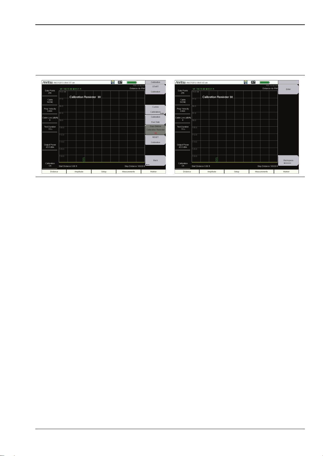
Calibration Reminder
You can set a reminder of the due date by pressing the Days Before Calibration Reminder
submenu key and entering a number with the number keypad. Complete the entry by
pressing the Enter submenu key or the instrument Enter key.
Figure 2-2. Days Before Calibration Reminder
2-3 Front Panel Overview
The PIM Master menu-driven interface is easy to use and requires little training. The
PIM Master uses a touch screen and keypad for data input. The five bottom menu keys and
eight submenu keys on the right side are touch screen keys. The menu and submenu keys will
vary depending upon the selected mode of operation, refer to “Mode Selector Menu”
on page 2-20.
Number keys 1 through 9 are dual purpose, depending upon the current mode of operation.
The dual-purpose keys are labeled with a number on the key itself with the alternate function
printed in blue above each of the keys. Use the blue Shift key to access the functions printed
on the panel. The Escape key, used for aborting data entry, is the button located above
number key 8. The four Arrow keys and the keypad can be used to change the value of an
active parameter.
MW82119B UG PN: 10580-00400 Rev. N 2-3
Page 20

2-3 Front Panel Overview Chapter 2 — PIM Master Overview
2
1
3
MW82119B PIM Master Front Panel
Figure 2-3. MW82119B PIM Master Front Panel
1. On/Off Button (and Battery and Power LEDs)
2. Number Keypad
3. Measurement Display (a Touch Screen)
2-4 PN: 10580-00400 Rev. N MW82119B UG
Page 21
Chapter 2 — PIM Master Overview 2-4 Front Panel Keys
1
4
2
5
7
6
3
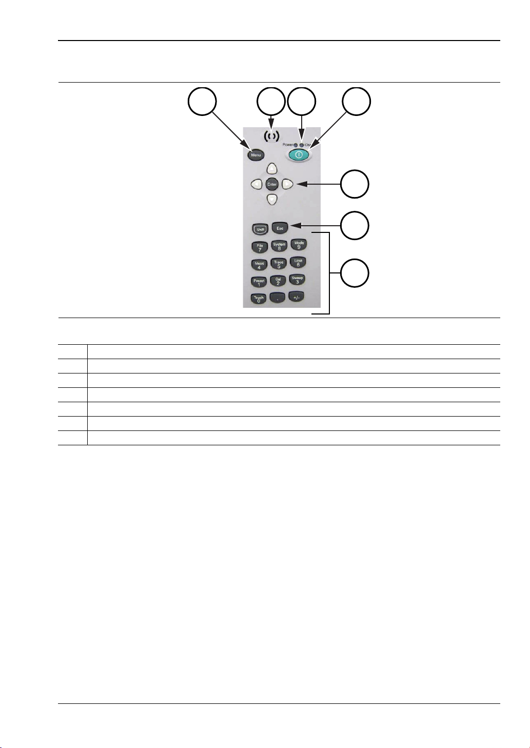
2-4 Front Panel Keys
Figure 2-4. Front Panel Layout
1. Menu Key
2. Speaker Grill
3. LED Indicators for Battery Charge and Power
4. On/Off Button
5. Arrow Keys and Enter Key in center
6. Shift Key and Escape Key
7. Number Keypad
The terms button and hard key refer to all of the buttons on the instrument face. These keys
perform as follows:
Menu Key
(item 1 in Figure 2-4)
Press the Menu key to display the Menu Key Screen, a grid of shortcut icons for installed
measurement modes and user-selected menus and setup files.
MW82119B UG PN: 10580-00400 Rev. N 2-5
Page 22

2-4 Front Panel Keys Chapter 2 — PIM Master Overview
On/Off Button
(item 4 in Figure 2-4)
Press this button to turn on power to the PIM Master. Press and hold this button to turn off
power.
Arrow Keys
(item 5 in Figure 2-4)
The four Arrow keys are used to scroll up, down, left, or right. The Arrow keys can often be
used (depending upon measurement selection) to change a value or to change a selection from
a list. In some measurements, the Left/Right arrow keys change values by different
increments than the Up/Down arrow keys. The Arrow keys are also used to move markers.
Enter Key
(item 5 in Figure 2-4)
Press this key to finalize data input.
Shift Key
(item 6 in Figure 2-4)
Press the Shift key and then press a number key to open the menu that is indicated in text
above the key number. When the Shift key is active, its icon is displayed at the top-right of the
measurement display area between the battery charge indicator and the submenu key labels.
Figure 2-5. Shift Key Icon
Esc Key
(item 6 in Figure 2-4)
Press this key to cancel any setting that is currently being made.
LED Indicators (above the On/Off Button)
(item 3 in Figure 2-4)
Battery Charge LED (Green)
The Battery Charge LED flashes if the battery is charging, and remains on steady when the
battery is fully charged.
Power LED (Green)
The Power LED remains on when the PIM Master is on.
2-6 PN: 10580-00400 Rev. N MW82119B UG
Page 23

Chapter 2 — PIM Master Overview 2-4 Front Panel Keys
Number Keypad
(item 7 in Figure 2-4)
Press these keys to directly input numbers. Number keys are also used to open menus when
used with the “Shift Key”. For example, press Shift and Touch (0) to initiate Touch Screen
Calibration.
+/– Key
(item 7 in Figure 2-4)
Press this key to change the sign of numbers that are entered with the number keys.
MW82119B UG PN: 10580-00400 Rev. N 2-7
Page 24
2-5 Top Connector Panel Chapter 2 — PIM Master Overview
1
3
2
54
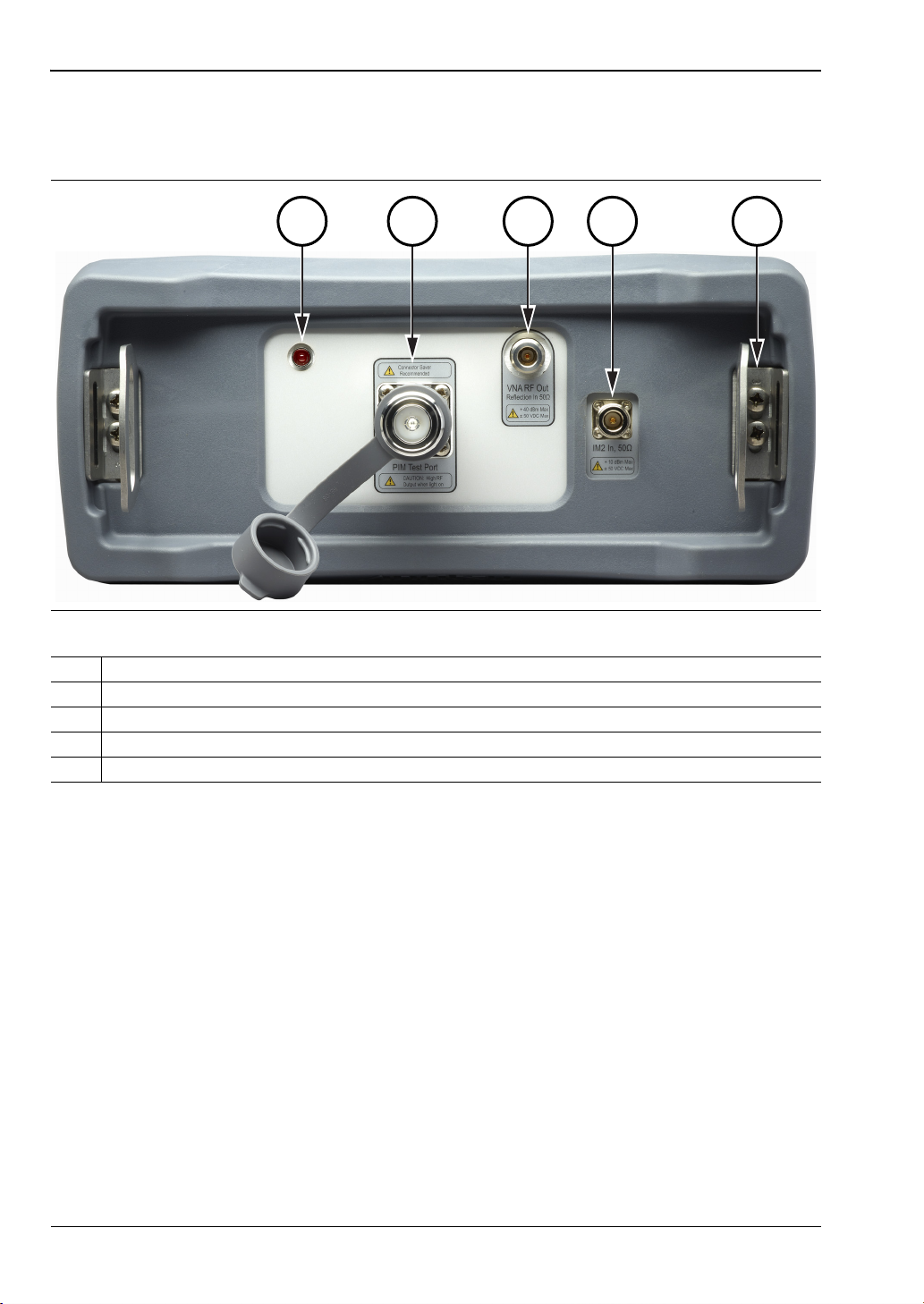
2-5 Top Connector Panel
The top connector panel includes the test port connectors and the Radio Frequency On light.
Figure 2-6. PIM Master Top Panel Layout
1. Indicator Light for RF On (Red)
2. PIM Test Connector, 7/16 DIN, female, 50 Ω
3. VNA RF Out Connector, Type-N, female, 50 ohms (Option 331)
4. IM2 In Connector, Type-N, female, 50 ohms (Option 902)
5. Strap Bracket (shown without strap), 2x
PIM Radio Frequency ON Light (item 1 in Figure 2-6)
This red indicator is illuminated when PIM RF output power is On.
PIM Test Connector (item 2 in Figure 2-6)
Type 7/16 DIN(f), 50 test port connector that is used to perform PIM versus Time, Swept
PIM, Noise Floor, and Distance-to-PIM (DTP) measurements.
To prevent damage to your instrument, do not use pliers or a plain wrench to tighten the DIN
connector. Do not over-tighten the connector. The recommended torque is 25 N ·m (~18 lbf·ft).
To prevent rotation, secure the PIM test connector or the recommended connector saver with
a wrench when attaching a test lead.
Refer to “Connector Saver” on page 1-5.
2-8 PN: 10580-00400 Rev. N MW82119B UG
Page 25

Chapter 2 — PIM Master Overview 2-5 Top Connector Panel
VNA RF Out Connector (item 3 in Figure 2-6)
VNA RF Out Connector, Type-N, female, 50 ohms (Option 331). This test port is available
only on instruments with Site Master Option 331. It is used to perform Return Loss, VSWR,
Cable Loss, and Distance-to-Fault (DTF) measurements. Hand tighten this connection. Do
not use a wrench.
IM2 In Connector (item 4 in Figure 2-6)
IM2 In Connector, Type-N, female, 50 ohms (Option 902). This test port is available only with
frequency Option 902. It is used to receive second order intermodulation products. Hand
tighten this connection. Do not use a wrench.
Strap Bracket (item 5 in Figure 2-6)
The Strap Brackets hold the Handle Strap and can accommodate a Carabiner. Note that each
bracket is secured to the PIM Master with 2 screws. The handle is sewn to the brackets, but is
not shown in the figure in order to reveal the bracket design. See Figure 2-23 on page 2-30 for
the complete bracket, mounted and in use.
MW82119B UG PN: 10580-00400 Rev. N 2-9
Page 26
2-6 Top Connector Panel -- Option 703 Chapter 2 — PIM Master Overview
5
3
2
1
4
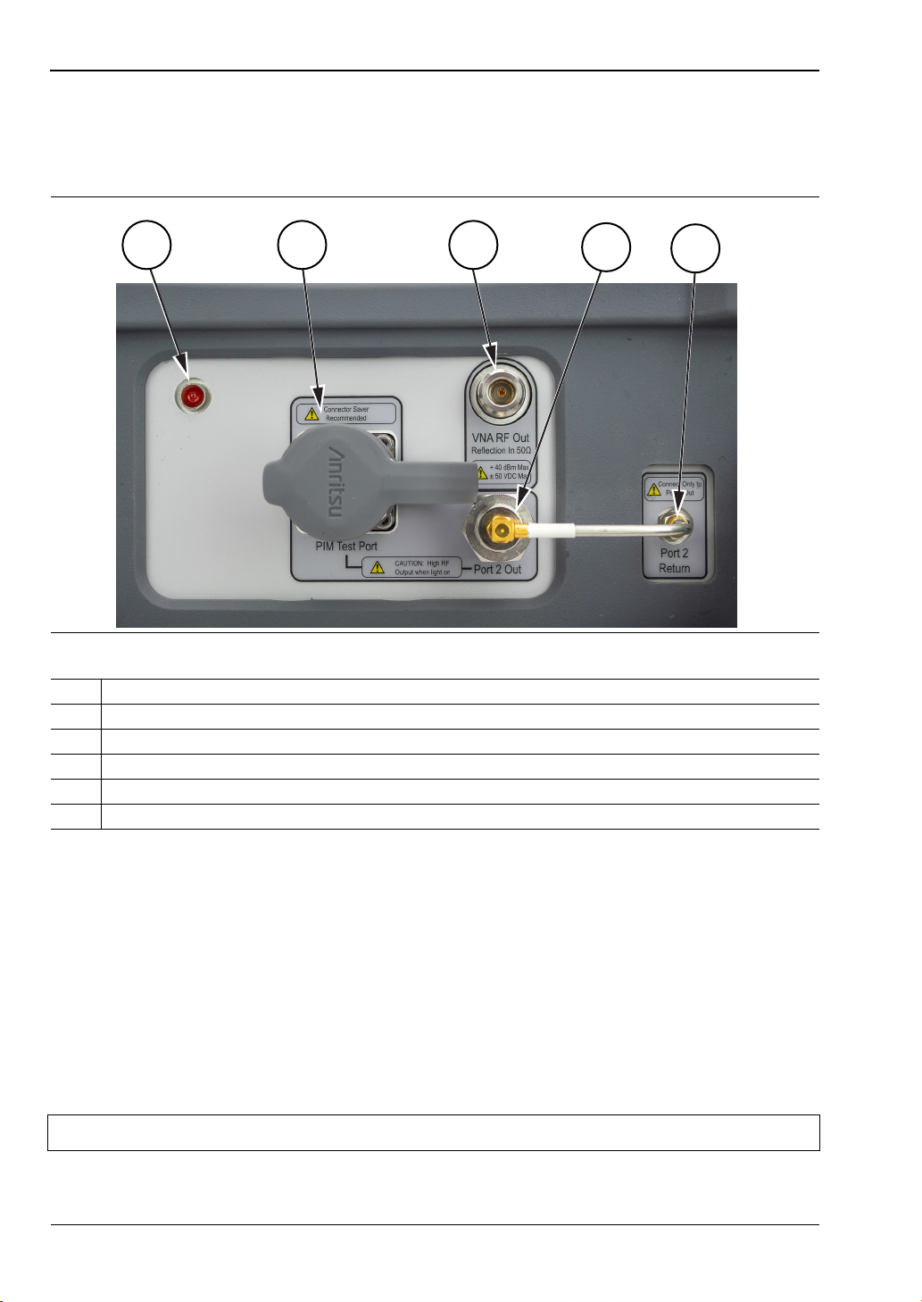
2-6 Top Connector Panel -- Option 703
The 2-port top connector panel includes the base features from Figure 2-6 plus those for the
2-port.
Figure 2-7. PIM Master Top Panel Layout: 2-Port
1. Indicator Light for RF On (Red)
2. PIM Test Connector, 7/16 DIN, female, 50 Ω
3. VNA RF Out Connector, Type-N, female, 50 Ω (Option 331)
4. Port 2 Out Connector, 4.3-10, female, 50 Ω (Option 703)
5. Port 2 Return Connector, Type SMA, female, 50 Ω (Option 703)
6. Strap Bracket (not shown), 2x
Port 2 Out Connector (item 4 in Figure 2-7)
VNA RF Out Connector, 4.3-10, female, 50 ohms (Option 703). This test port is available only
on instruments with 2-Port LTE Option 703. It is used to perform Return Loss, VSWR, Cable
Loss, and Distance-to-Fault (DTF) measurements. Hand tighten this connection. Do not use a
wrench.
Port 2 Return Connector (item 5 in Figure 2-7)
Port 2 Return Connector, SMA, female, 50 ohms (Option 703). This test port is available only
on instruments with 2-Port LTE Option 703. Hand tighten this connection. Do not use a
wrench.
Note Use care to use all wrenches in such a way that the rigid cable is not impacted.
2-10 PN: 10580-00400 Rev. N MW82119B UG
Page 27

Chapter 2 — PIM Master Overview 2-7 Side Panel Connectors
7
5
1
3
2
4
6
8
2-7 Side Panel Connectors
The side connector panel includes connectors for External Power, Ethernet/LAN, USB
interface, and GPS.
Figure 2-8. PIM Master Side Panel Overview
1. External Power
2. LAN Connection, RJ45
3. USB Interface, Type A
4. USB Interface, 5-pin mini-B
5. Auxiliary 1 (factory use only)
6. Auxiliary 2 (factory use only)
7. GPS Connector, SMA female (with Option 31)
8. Legend (icons identify connection types)
MW82119B UG PN: 10580-00400 Rev. N 2-11
Page 28

2-7 Side Panel Connectors Chapter 2 — PIM Master Overview
External Power (item 1 in Figure 2-8)
This 2.1 mm by 5.5 mm barrel connector is used to power the unit and for battery charging.
Input is 12 VDC to 15 VDC at up to 5.0 A.
When using the AC-DC Adapter, always use a three-wire power cable that is
Warning
connected to a three-wire power line outlet. If power is supplied without grounding
the equipment in this manner, then the user is at risk of receiving a severe or fatal
electric shock.
LAN Connection (item 2 in Figure 2-8)
The RJ45 connector is used to connect the PIM Master to a local area network. Integrated
into this connector are two LEDs. The amber LED shows the presence of a 10 Mbit/s LAN
connection when on, and a 100 Mbit/s LAN connection when off. The green LED flashes to
show that LAN traffic is present. For additional information about the LAN connection,
Ethernet connection, and DHCP, refer to Appendix F, “LAN and DHCP”.
USB Interface – Type A (item 3 in Figure 2-8)
This interface has two connectors for flash drive and USB Power Sensor. The MW82119B
PIM Master can also be a USB Host and allow various USB Flash Memory devices to be
connected to the instrument for storing measurements, setups, files, and firmware upgrades.
Either USB connection can be used with a USB power sensor (but only one power sensor at a
time).
USB Interface – Type Mini-B (item 4 in Figure 2-8)
The USB 2.0 interface can be used to connect the MW82119B PIM Master directly to a PC for
data transfer. The first time the PIM Master is connected to a PC, the normal USB device
detection by the computer operating system will take place. Drivers are available for
Windows XP (or later).
Note
For proper detection, Line Sweep Tools should be installed on the PC prior to
connecting the PIM Master to the USB port.
GPS Antenna Connector (Option 31) (item 7 in Figure 2-8)
The GPS antenna connection on the PIM Master is type SMA(F). Selectable +3 VDC or
+5 VDC antenna power.
To prevent damage to your instrument, do not use pliers or a plain wrench to tighten the
SMA connector. Do not overtighten the connector. The recommended torque is 8 lbf·in
(0.9 N·m or 90 N·cm).
2-12 PN: 10580-00400 Rev. N MW82119B UG
Page 29
Chapter 2 — PIM Master Overview 2-8 Measurement Display Overview
Date/Time GPS Battery Indicator
Measurement Title Area
Main Graph Area
Submenu
Keys
Main Menu Keys
Numerical Measurement Result Area
Instrument
Settings
Summary
2-8 Measurement Display Overview
Throughout this manual, typical measurement displays are shown for the basic measurement
modes of the PIM Master. Note that the images shown in this manual may be different from
any images that are displayed on your PIM Master.
Front Panel Display Areas
Figure 2-9. Front Panel Overview
MW82119B UG PN: 10580-00400 Rev. N 2-13
Page 30

2-8 Measurement Display Overview Chapter 2 — PIM Master Overview
Main Menu Keys
The PIM Master menu-driven interface is easy to use and requires little training. The five
Main Menu keys are located below the measurement display. These five keys are used to
display the function-specific menus in the active menu (submenu labels). These Main Menu
keys vary in function based on the selected mode of operation (Shift, Mode (9)) or
measurement type within a mode. Refer to “Mode Selector Menu” on page 2-20 for more
information on changing the instrument mode. Table 2-1 lists from left to right the Main
Menu Key labels for each mode of instrument operation.
Tab le 2-1. Mode-Dependent Main Menu Keys Located at Bottom of Measurement Display
Mode/Measurement
Type Key 1 Key 2 Key 3 Key 4 Key 5
PIM vs. Time Freq Amplitude Setup Measurements Marker
Noise Floor Freq Amplitude Setup Measurements Marker
DTP Distance Amplitude Setup Measurements Marker
Swept PIM Freq Amplitude Setup Measurements Marker
High Accuracy
Power Meter
Cable & Antenna Freq/Dist Amplitude Sweep/Setup Measurements Marker
a
Amplitude Average Zero/Cal Limit
a.If High Accuracy Power Meter (option 19) is installed.
Submenu Keys
The eight submenu keys are located to the right of the measurement display. They change
function depending upon the current mode and current menu selection. The current submenu
title is shown at the top of the active function block (submenu key labels). For an example,
refer to item 6 in Figure 2-10 on page 2-15.
2-14 PN: 10580-00400 Rev. N MW82119B UG
Page 31

Chapter 2 — PIM Master Overview 2-8 Measurement Display Overview
1
3
710
9
2
5
4
6
8
Front Panel Layout, PIM vs. Time
The following three figures are provided to identify display components in different
measurement modes. The image and measurement details shown on your instrument may
differ from the examples in this user guide.
2-
Figure 2-10. Front Panel Layout with PIM vs. Time Display
1. Real Time Clock (followed by GPS Coordinates if Option 31 is installed)
2. Main Graph Area or Sweep Window or Measurement Grid
3. Limit Line (Green line, set from Limit menu)
4. Battery Status Icon
5. Instrument Mode and Measurement Title
6. Submenu Keys or Active Function Block
7. PIM Summary Table
8. Pass/Fail Indicator (set from Limit menu)
9. Main Menu Keys
10. Instrument Settings Summary
MW82119B UG PN: 10580-00400 Rev. N 2-15
Page 32

2-8 Measurement Display Overview Chapter 2 — PIM Master Overview
11
10
1
3
6
5
4
7
2
89
Front Panel Layout, Distance-to-PIM
Figure 2-11. Front Panel Layout with Distance-to-PIM Display
1. Real Time Clock (followed by GPS Coordinates if Option 31 is installed)
2. Reference Limit Line (blue line, set from Limit menu)
3. Main Graph Area or Sweep Window or Measurement Grid
4. Marker on Distance-to-PIM Measurement Trace
5. Battery Status Icon
6. Instrument Mode and Measurement Title
7. Submenu Keys or Active Function Block
8. Progress Indicator
9. Marker Table (set to Large)
10. Main Menu Keys
11. Instrument Settings Summary
2-16 PN: 10580-00400 Rev. N MW82119B UG
Page 33

Chapter 2 — PIM Master Overview 2-8 Measurement Display Overview
1
3
711
10
2
5
4
6
13
9
8
12
Front Panel Layout, Swept PIM
Figure 2-12. Front Panel Layout with Swept PIM Display
1. Real Time Clock (followed by GPS Coordinates if Option 31 is installed)
2. Main Graph Area or Sweep Window or Measurement Grid
3. Swept PIM Measurement Trace (green trace and yellow trace)
4. Battery Status Icon
5. Instrument Mode and Measurement Title
6. Submenu Keys or Active Function Block
7. PIM Summary Table
8. Limit Line (green)
9. Progress Indicator
10. Main Menu Keys
11. Instrument Settings Summary
12. Pass/Fail indicator
13. Marker and marker data automatically displayed
The yellow trace is created by holding F1 fixed and sweeping F2. The green trace is
created by holding F2 fixed and sweeping F1. The PIM Summary Table displays the
frequencies that are used to generate each sweep. In this display, the green trace
(Sweep #2) is visible only in the first few MHz of the sweep. Note that the PIM
Summary Table displays the Sweep numbers in yellow and green.
MW82119B UG PN: 10580-00400 Rev. N 2-17
Page 34

2-8 Measurement Display Overview Chapter 2 — PIM Master Overview
1
3
710
9
2
5
4
6
8
11
Front Panel Layout, C&AA (Option 331)
Figure 2-13. Front Panel Layout with Return Loss Display
1. Real Time Clock (followed by GPS Coordinates if Option 31 is installed)
2. Main Graph Area or Sweep Window or Measurement Grid
3. Limit Line (green)
4. Battery Status Icon
5. Instrument Mode and Measurement Title
6. Submenu Keys or Active Function Block
7. Marker Table
8. Return Loss Measurement Trace
9. Main Menu Keys
10. Instrument Settings Summary
11. Marker and marker data automatically displayed for active Marker [M2]
2-18 PN: 10580-00400 Rev. N MW82119B UG
Page 35

Chapter 2 — PIM Master Overview 2-9 Secondary Function Menus
2-9 Secondary Function Menus
Pressing the Shift key and then a number key selects the menu function that is printed above
the key number (Figure 2-14).
Figure 2-14. Keypad and Secondary Function Menus
Not all Secondary Function Menus are active in various operation Modes. If any one of these
menus is available in a specific instrument Mode of operation, then it can be called from the
number keypad. It may also be available from a main menu key or a submenu key.
The 10 Secondary Function Menus are:
0 Touch Screen Calibration (and Arrow Navigation)
1Preset
2Calibration
3 Sweep
4 Measurements
5 Trace
6Limit
7File
8System
9MODE
MW82119B UG PN: 10580-00400 Rev. N 2-19
Page 36

2-10 Mode Selector Menu Chapter 2 — PIM Master Overview
2-10 Mode Selector Menu
To access the functions under the Mode menu, select the Shift key, then the Mode (9) key.
Use the directional Arrow keys to highlight the selection, and press the Enter key to select.
The list of modes that appears in this menu will vary depending upon the options that are
installed and activated in your instrument. Figure 2-15 is an example of the Mode menu.
Your instrument may not show the same list.
Figure 2-15. Mode Selector Menu
2-20 PN: 10580-00400 Rev. N MW82119B UG
Page 37

Chapter 2 — PIM Master Overview 2-11 Menu Key
2-11 Menu Key
Press the Menu key to display the Menu Key Screen, a grid of icons for installed
measurement modes and shortcuts to user-selected menus and setup files.
Figure 2-16 shows the Menu key screen without any user shortcuts. Touch one of the icons in
the top two rows to change modes. The icons that are shown here are preinstalled and cannot
be moved or deleted. The display of the Menu screen will vary depending on instrument
model, firmware version, and installed options. The image in Figure 2-16 may differ from the
menu on your instrument.
Figure 2-16. Menu Key Screen, Icons for Installed Measurements
Note
MW82119B UG PN: 10580-00400 Rev. N 2-21
The High Accuracy Power Meter icon is present only if Option 19 is installed.
See Appendix A, “Other Documents” for information about this publication.
Page 38

2-11 Menu Key Chapter 2 — PIM Master Overview
Figure 2-17 shows the Menu key screen with shortcut icons for features of the installed
measurement modes and additional user-defined shortcuts to menus and setup functions.
Press and hold down any key for a few seconds to add a shortcut to this screen. For example,
to create a shortcut for PIM versus Time measurements, open the PIM Master Measurements
menu and hold down on the PIM vs. Time submenu key for a few seconds. The PIM Master
displays a grid (occupied locations show their shortcut), then select the location for the
shortcut. The display of the Menu screen will vary depending on instrument model, firmware
version, and installed options. The image in Figure 2-17 may differ from the menu on your
instrument.
Figure 2-17. Menu Key Screen, Icons for Installed Measurements and Shortcuts
User-defined shortcuts stay in memory until deleted. To delete or move a shortcut button,
press the Menu key, then press and hold the shortcut for approximately three seconds. The
Customize Button dialog box opens to allow a button to be deleted or moved. Press Esc to exit
the Menu shortcut display.
The Master Reset will delete all user-created shortcut icons from the Menu screen.
Refer to the “Reset Menu” on page 5-7 for additional information.
Note
To retain shortcuts during a firmware update, select the "Save & restore user data"
option shown in Figure E-5 on page E-8.
2-22 PN: 10580-00400 Rev. N MW82119B UG
Page 39

Chapter 2 — PIM Master Overview 2-11 Menu Key
Help for the Menu shortcut screen is available by pressing the question mark icon in the
lower-right corner of the display.
Figure 2-18. Menu Help
MW82119B UG PN: 10580-00400 Rev. N 2-23
Page 40

2-12 Touch Screen Chapter 2 — PIM Master Overview
2-12 Touch Screen
The touch screen and keypad are used for data entry. The sweep window and surrounding
screen areas provide measurement information (see Figure 2-9, “Front Panel Overview”
on page 2-13).
Graphical User Interface (GUI)
The measurement display, or sweep window, provides measurement trace data. Above the
grid and trace data, additional measurement data are displayed, and the analyzer mode is
shown in the top-right corner. The lower area of the grid may be reduced in size to display an
optional data window, such as a table of measurement data or marker data. To the left of the
grid and trace data is the instrument settings summary; below the grid are the five main
menu touch keys; to the right are the submenu touch keys. For a list of the main menu keys
in different instrument modes, refer to “Main Menu Keys” on page 2-14.
The five main menu touch keys and (up to) eight submenu touch keys are available in all
analyzer Modes, providing control of measurement settings. In addition, you can touch other
areas of the display screen to perform tasks that are also available from the menu keys.
For example:
• If you touch the Scale setting on the left side of the display (Instrument Settings
Summary), then the Amplitude menu is displayed, and the Scale submenu key is
active. Scale is displayed in PIM vs. Time and Swept PIM measurements.
• If you touch Data Points (Instrument Settings Summary), then the DTP Parameters
setup window is displayed, and the Data Points parameter is selected (Distance-to-PIM
measurements.
• If you touch Cable (Instrument Settings Summary), then the Cable List is displayed
(Distance-to-PIM measurements).
• If you place a marker on the screen, then you can touch the measurement trace to
relocate the marker.
• If you touch the file type list box in one of the file management dialog boxes, then you
can open the Filetype drop-down list to select a file type.
Main Menu Touch Screen Keys
The main menu key functions change to match specific instrument Mode settings. The main
menu keys generate function-specific submenus. The measurement modes are selected by
pressing the Shift key and then the Mode (9) key. For more details about the Mode menu,
refer to “Mode Selector Menu” on page 2-20.
Submenu Touch Screen Keys
The submenu touch keys are located in the active function block (submenu key labels) along
the right edge of the display. The submenu labels change as instrument measurement and
parameter settings change. The current submenu title is shown at the top of the submenu key
block. An example of the keys is shown in Figure 2-10 on page 2-15. Additional details are
described in Section 2-8 “Measurement Display Overview” on page 2-13.
2-24 PN: 10580-00400 Rev. N MW82119B UG
Page 41

Chapter 2 — PIM Master Overview 2-13 Touch Screen Calibration
2-13 Touch Screen Calibration
The Calibrate Touch Screen submenu key is in the “System Menu” on page 5-3. When pressed,
the touch screen calibration message box is displayed with instructions for calibration.
Calibration optimizes the response of touch input. You touch targets in sequence as they are
displayed on the touch screen. This requires less than one minute.
Calibration is recommended if your touch inputs do not correspond to the appropriate
locations on the screen. After the information box is displayed, press Enter to begin
calibration, or press Esc to cancel.
You can also press 1 to use arrow navigation.
Calibrate Touch Screen Shortcut
You can access touch screen calibration by pressing Shift then Touch (0). This displays the
touch screen calibration message box. Press Enter to begin calibration, or press Esc to cancel.
This shortcut can be used if your touch inputs do not correspond to the appropriate locations
on the screen to such an extent that you cannot access the Calibrate Touch Screen submenu
key.
Arrow Navigation
If the touch screen is not functioning, you can use Arrow Navigation to simulate pressing the
touch screen main menu keys and submenu keys. From the touch screen calibration message
box, press 1 to use arrow navigation. This displays the arrow navigation message box. Press 1
again to enter the arrow navigation mode, or press Esc to cancel. Note that entering arrow
navigation mode disables the touch function of the touch screen.
In arrow navigation mode, a red selection box surrounds a key (see Figure 2-19 on page 2-26
in which the Carrier F1 submenu key is selected). To move the red selection box, use the
Arrow keys above the number keypad (see Figure 2-14 on page 2-19). Then press the Menu
key to activate the selected touch screen key. Note that only the main menu keys and
submenu keys can be activated by using Arrow Navigation. When using the File management
menus for Copy, Recall, and Delete, however, you can press the +/– key to change focus of the
arrow navigation from the menu keys to the lists in the dialog box and back to the menu keys.
Arrow navigation places a green selection box around the Source or Destination file group
(depending on the selection toggled in the Scroll submenu key). You can then use the arrow
keys to navigate and select files. This feature does not move the arrow navigation selection
box into any other areas of the touch screen.
To save a measurement in arrow navigation mode, press Shift then File (7). Use the Arrow
keys to move the red selection box to the Save Measurement As submenu key. This submenu
key must be used because the arrow navigation mode cannot be used to change data in popup
windows in the measurement display. Filenames are determined by the current setting of the
Save Measurement As submenu key. Refer to “Save Measurement As” on page 4-12.
You can save a JPEG image of the current display screen by pressing three keys, Shift, then
Decimal, then +/–. The JEPG image shows screen data, but does not contain the additional
measurement information that accompanies a saved measurement in a *.pim measurement
file.
MW82119B UG PN: 10580-00400 Rev. N 2-25
Page 42

2-14 Parameter Setting Chapter 2 — PIM Master Overview
To return to normal touch entry mode, reboot the instrument (turn power Off and then On). If
your touch screen has been damaged, then refer to Section 1-2 “Instrument Description”
on page 1-3.
Figure 2-19. Arrow Navigation Mode
2-14 Parameter Setting
Pop-up list boxes or edit boxes are used to provide selection lists and selection editors. Scroll
through a list of items or parameters with the Arrow keys or by using the touch screen. Select
numerical values by scrolling with the Arrow keys or by entering the digits directly from the
number keypad. These list boxes and edit boxes frequently display a range of possible values
or limits for possible values.
Finalize the input by pressing the Enter key. At any time before finalizing the input, press the
escape (Esc) key to abort the change and retain the previously existing setting.
2-26 PN: 10580-00400 Rev. N MW82119B UG
Page 43

Chapter 2 — PIM Master Overview 2-15 Symbols and Indicators
Shift
2-15 Symbols and Indicators
The following symbols, icons, and indicators convey the instrument status or condition on the
display. The colors shown here are in the standard or default display mode.
Table 2-2. Symbols and Icons
Symbol Description
Green: Battery is 30 % to 100 % charged
Yellow: Battery is 10 % to 30 % charged
Red: Battery 0 % to 10 % charged
Green with Black Plug body: Battery is fully charged and
external power is applied
Lightning Bolt: Battery is being charged (any color symbol)
Red Plug body: External power is applied, and no battery is
installed, or battery has lost communications with the instrument
Storage Icon: Image of a 3.5 inch floppy disk drive, shortcut to the
Save Menu
Camera Icon: Saves a JPEG image of the current screen display
Shift Key Icon: This icon is displayed between the battery symbol
and the submenu keys after the Shift key has been pressed, and
until another key is pressed.
GPS Icon: This icon is displayed right after the date and time
when GPS is available. For additional details, refer to
Chapter 6, “GPS (Option 31)”.
Power Button with Power LED and Charge LED: This is a
physical button with LED indicators. It is located near the number
keypad.
The battery symbol above the display indicates the charge remaining in the battery. The
colored section inside the symbol changes size and color with the charge level. The Battery
Charge LED (adjacent to the On/Off button) flashes when the battery is charging, and
remains on steady when the battery is fully charged.
Use only Anritsu-approved batteries, adapters, and chargers with this instrument.
Caution
Anritsu Company recommends removing the battery for long-term storage of the
instrument.
Touch the storage icon to open the touch screen keyboard for saving measurements, setups,
limit lines, or screen display JPEG files (see Figure 4-1, “Save Dialog Box” on page 4-4).
MW82119B UG PN: 10580-00400 Rev. N 2-27
Page 44

2-16 Soft Carrying Case Chapter 2 — PIM Master Overview
2-16 Soft Carrying Case
The PIM Master can be operated while in the soft carrying case by opening the front flap
(secured by two zippers).
Figure 2-20. Case Open to Operate the PIM Master
The case is padded on all sides and contains protective inserts in the front and back panels.
An additional flap at the top of the rear panel can be folded over the PIM Master top
connector panel for additional protection.
2-28 PN: 10580-00400 Rev. N MW82119B UG
Page 45

Chapter 2 — PIM Master Overview 2-16 Soft Carrying Case
To install the instrument into the soft carrying case:
1. The Back panel of the case is secured with two zippers that start at the bottom of each
side. Fully close the front panel of the case to help support the shape of the case while
you are inserting the PIM Master into the back.
2. Place the soft carrying case face down on a stable surface, with the front panel fully
closed and laying flat.
3. Open the zippered back of the case.
4. Insert the instrument face down into the case, taking care that the connectors are
properly situated in the case top opening. Refer to the tilting of the instrument as
shown in Figure 2-21. Note that the instrument in this figure may differ from your
model. The method of insertion remains the same.
Figure 2-21. Putting PIM Master into Soft Case
5. Close the back panel and secure with one or both zippers to securely enclose the
PIM Master.
6. Two pairs of additional straps cross over the top of the PIM Master (inside the strap
brackets) to keep the soft case closed securely around the instrument. These straps
have hook-and-loop fasteners. See Figure 2-23 on page 2-30.
7. An additional flap (sewn to the back cover) with a protective insert can be folded over
the center of the top connector panel. It attaches to the front of the case by
hook-and-loop fasteners. This flap is shown closed in Figure 2-22 on page 2-30.
MW82119B UG PN: 10580-00400 Rev. N 2-29
Page 46

2-16 Soft Carrying Case Chapter 2 — PIM Master Overview
A side flap provides access to the side panel. Inside and below the panel is a pocket to hold a
wireless router. The router connecting cables can be enclosed by the side flap.
Figure 2-22. Access to Side Panel
Figure 2-23. Instrument Enclosed in the Soft Carrying Case
2-30 PN: 10580-00400 Rev. N MW82119B UG
Page 47

Chapter 2 — PIM Master Overview 2-17 Tilt Bail Stand
2-17 Tilt Bail Stand
A tilt bail is attached to the back of the PIM Master for desktop operation. To deploy the tilt
bail, pull the bottom of the tilt bail away from the back of the instrument. To store the tilt
bail, push the bottom of the bail towards the back of the instrument until it attaches to the
PIM Master.
Figure 2-24. Tilt Bail Extended
MW82119B UG PN: 10580-00400 Rev. N 2-31
Page 48

2-17 Tilt Bail Stand Chapter 2 — PIM Master Overview
2-32 PN: 10580-00400 Rev. N MW82119B UG
Page 49

Chapter 3 — Quick Start Guide
The Anritsu PIM Master is capable of producing 80 Watts of RF power in the
cellular communications bands. Users must take precautions to minimize
exposure to these RF fields:
Always terminate the PIM output port of the test equipment into a load, a
loaded line, or a line that will radiate or absorb the energy before beginning
a PIM test.
Warning
3-1 Introduction
This chapter describes the basic setup and use of the PIM Master for performing Line Sweep
(cable and antenna analysis, or CAA) and PIM measurements (Option 331). Tasks common to
all PIM measurements are also introduced here.
Confirm that the PIM Master RF power is off after a PIM test.
Always confirm that the PIM RF power is off before disconnecting a coaxial
connection, otherwise RF burns may result. Immediate burns to fingers or
eyes can result from exposure to live connectors.
Ensure that all antennas under test are placed so that no personnel are
exposed to RF levels that exceed the maximum allowable exposure.
MW82119B UG PN: 10580-00400 Rev. N 3-1
Page 50

3-2 Measurement Mode Selection Chapter 3 — Quick Start Guide
3-2 Measurement Mode Selection
Press the Menu key and use the touch screen to select the appropriate measurement icon.
Figure 3-1. Menu Screen with Icons for Installed Measurement Modes
Note The display of the Menu screen will vary depending on installed options.
3-2 PN: 10580-00400 Rev. N MW82119B UG
Page 51

Chapter 3 — Quick Start Guide 3-3 Cable & Antenna Analyzer Measurements (Option 331)
Measurement 2/2
Smith Chart
1-Port Phase
Back
Measurement 1/2
More
Return Loss
Cable Loss
DTF
Return Loss
DTF VSWR
VSWR
Display Format
Single Dual
Active Display
Top Bottom
Cable Loss
And
DTF-RL
3-3 Cable & Antenna Analyzer Measurements (Option 331)
Set the instrument to Cable & Antenna Analyzer mode (refer to Section 3-2 “Measurement
Mode Selection” or “Menu Key” on page 2-21). This section is a brief introduction to cable and
antenna analysis. For more details, refer to the Cable and Antenna Analyzer Measurement
Guide that is listed in Appendix A.
Select the Measurement Type
Press the Measurement main menu key and select the appropriate measurement.
Figure 3-2. C&AA Measurement Menus
Set the Frequency
MW82119B UG PN: 10580-00400 Rev. N 3-3
1. Press the Freq/Dist main menu key.
2. Press the Start Freq submenu key and use the keypad or the arrow keys to enter the
start frequency.
3. Press the Stop Freq submenu key and use the keypad or the arrow keys to enter the stop
frequency.
Page 52

3-3 Cable & Antenna Analyzer Measurements (Option 331) Chapter 3 — Quick Start Guide
Set the Amplitude
1. Press the Amplitude main menu key.
2. Press the To p submenu key and use the keypad or the arrow keys to edit the top scale
value. Press Enter to set.
3. Press the Bottom submenu key and use the keypad or the arrow keys to edit the bottom
scale value. Press Enter to set.
Note
For Amplitude in Smith Chart measurements, refer to “Smith Chart” on page 2-23
of the Cable & Antenna Measurement Guide listed in Appendix A.
Turn on Markers
1. Press the Marker main menu key.
2. Press the Marker 1 2 3 4 5 6 submenu key and select the marker number 1 button using
the touch screen. The underlined number on the Marker submenu key indicates the
active marker.
3. Use the arrow keys or the keypad to move the marker. The current value for the
selected marker is shown above the upper-left corner of the graph. It is also possible to
drag the marker using the touch screen.
4. Delta Markers are available for each of the six reference markers. For the selected
marker, Toggle the Delta On/Off submenu key to turn on the Delta marker.
Peak/Valley Auto Markers
When making Return Loss and VSWR measurements, the Peak/Valley Auto feature can be
used to automatically turn on Marker 1 to peak, Marker 2 to valley, and display M1 and M2
in the Marker Table. This feature is not available for DTF measurements.
1. Press the Marker main menu key.
2. Press the Peak/Valley Auto key.
3-4 PN: 10580-00400 Rev. N MW82119B UG
Page 53

Chapter 3 — Quick Start Guide 3-3 Cable & Antenna Analyzer Measurements (Option 331)
Single Limit Line
1. Press Shift and then Limit (6) to enter the Limit menu.
2. Press the Limit On/Off key to turn on the Limit.
3. Press Single Limit and then use the numeric keypad or the arrow keys to change the
limit value and then press Enter.
Note
4. Press the Limit Alarm key to turn on or off the Limit Alarm.
Refer to the Cable & Antenna Measurement Guide listed in Appendix A for
creating multi-segment limit lines.
Figure 3-3. Single Limit Lines
MW82119B UG PN: 10580-00400 Rev. N 3-5
Page 54

3-3 Cable & Antenna Analyzer Measurements (Option 331) Chapter 3 — Quick Start Guide
DTF Setup
1. Press the Measurements main menu key and select DTF Return Loss or DTF VSWR.
2. Press the Freq/Dist main menu key.
3. Press the Units submenu key and select m to display distance in meters or ft to display
distance in feet.
4. Press DTF Aid and use the touch screen, or arrow keys to navigate through all the DTF
parameters.
a. Set Start Distance and Stop Distance. Stop Distance needs to be smaller than
Dmax.
b. Enter the Start and Stop frequencies.
c. Press Cable, select the appropriate cable from the cable list and press Enter.
d. Press Continue.
Figure 3-4. DTF Aid
5. Press Shift then Calibrate (2) to calibrate the instrument. Refer to “Calibrate with OSL
Calibration” on page 3-7 for additional information.
6. Press the Marker main menu key and set the appropriate markers.
7. Press Shift and Limit (6) to enter and set the appropriate limit lines.
8. Press Shift and File (7) to save the measurement. Refer to Chapter 4, “File
Management” for details.
3-6 PN: 10580-00400 Rev. N MW82119B UG
Page 55

Chapter 3 — Quick Start Guide 3-3 Cable & Antenna Analyzer Measurements (Option 331)
RFOUT/REFLECTION
TEST PORT
TEST PORT CABLE (OPTIONAL)
OPEN
LOAD
SHORT
CALIBRATION
Calibrate with OSL Calibration
Note
Refer to the Cable & Antenna Measurement Guide listed in Appendix A for
calibration details.
1. Press the Freq/Dist main menu key and enter the appropriate frequency range
2. Press Shift then Calibrate (2) key.
3. Select Standard or FlexCal.
4. Press Start Cal and follow instructions on screen.
5. Connect Open to RF Out and press the Enter key.
6. Connect Short to RF Out and press the Enter key.
7. Connect Load to RF Out and press the Enter key.
8. Verify that the calibration has been properly performed by checking that the Cal Status
message is now displaying “ON, Standard” or “ON, FlexCal”.
Figure 3-5. Calibration Setup with OSL Cal Standards
MW82119B UG PN: 10580-00400 Rev. N 3-7
Page 56

3-4 Passive Intermodulation (PIM) Measurements Chapter 3 — Quick Start Guide
3-4 Passive Intermodulation (PIM) Measurements
Set the instrument to PIM Analyzer mode (refer to “Mode Selector Menu” on page 2-20 or
“Menu Key” on page 2-21). This section is a brief introduction to PIM analysis. For more
details, refer to the Passive Intermodulation Analyzer Measurement Guide that is listed in
Appendix A.
Preparing for PIM Measurements
Along with your PIM Master, you need tools and components that are provided in the
accessory kit, and you need to set up the instrument for your planned measurements.
Checking Required Tools and Components
The following items are supplied with your PIM Master accessory kit or can be ordered
separately as individual components. Consult your Technical Data Sheet for part numbers.
• Test cable
• Connector Saver (refer to “Connector Saver” on page 1-5)
• RF Adapters
• PIM Standard
• Low PIM Termination
• Torque Wrench
• Adjustable Wrench
• Cleaning Kit
Setting Up the PIM Master
To prepare the PIM Master for measuring PIM, put the it in PIM Analyzer mode.
Before calibrating the PIM Master, set the parameters for the four measurement types. This
will eliminate the need for recalibrating due to changing parameters. To set up the
parameters for the four measurement types, perform these steps. See Passive
Intermodulation Analyzer Measurement Guide that is listed in Appendix A for complete
instructions for set up and calibration of the instrument.
To set up PIM vs. Time measurements:
1. Press the Measurements main menu key and then press the PIM vs. Time submenu key.
2. Press the Freq main menu key, then select the input frequencies for the F1 and F2
carriers, and then select the intermodulation order.
a. Press the Carrier F1 submenu key and set the desired frequency.
b. Press the Carrier F2 submenu key and set the desired frequency.
c. If necessary, press the Intermod Order submenu key until the desired setting is
underlined (3rd, 5th, or 7th).
d. If necessary, press the Band Select submenu key until the desired High or Low
setting is underlined (or one of the following with Option 194: PCS or PCS/AWS,
Option 600: 1900 MHz or 600 MHz, Option 902: IM2 or GSM).
3. Press the Setup main menu key to set the power level and test duration.
3-8 PN: 10580-00400 Rev. N MW82119B UG
Page 57

Chapter 3 — Quick Start Guide 3-4 Passive Intermodulation (PIM) Measurements
To set up Distance to PIM measurements:
1. Press the Measurements main menu key and then press the Distance-to-PIM submenu
key.
2. Press the Setup main menu key, then the DTP Aid submenu key.
3. On the DTP Parameters screen, use the touch screen to enter or select values for
Distance, Data Points, and Cable type (or enter Cable Loss and Propagation Velocity).
To set up Noise Floor measurements:
1. Press the Measurements main menu key and then press the Noise Floor Measurements
submenu key.
2. Choose Time View or Spectrum View and if Spectrum View whether to calibrate.
3. Press Freq key to set.
To set up Swept PIM measurements:
1. Press the Measurements main menu key and then press the Swept PIM submenu key.
2. Choose 1- or 2- Port mode.
3. Choose High or Low band (2-port mode only works with Low band).
4. Select 3rd, 5th, or 7th intermodulation order.
5. Press Swept PIM Aid to set up the markers for Swept PIM measurements.
After setting up the measurement types, visually inspect all RF connectors on the test
instrument, the test lead, the PIM standard, and the Low PIM termination. Clean
connections each day prior to first use.
Note
Save your instrument settings in a setup file to allow easy recall of frequently used
settings.
MW82119B UG PN: 10580-00400 Rev. N 3-9
Page 58

3-4 Passive Intermodulation (PIM) Measurements Chapter 3 — Quick Start Guide
Calibrating the PIM Analyzer
Caution During calibration, RF power is present, and the red RF On light is illuminated.
Calibrations are temperature-dependent. A temperature deviation of approximately
20 degrees Celsius voids an existing calibration. Two temperatures are displayed in a white
font (in all PIM measurement modes) in the Instrument Settings Summary, just above the
Calibration On/Off message. One is the temperature in the PIM Master now, and the other is
the temperature in the PIM Master at calibration.
When the current temperature (labeled now) changes ±8 °C of the calibration limit, the font
color of the current temperature is displayed in yellow. This color changes to red if the current
temperature exceeds the calibration limit ±10 °C from the calibration limit. N/A is displayed
for the calibration temperature when no valid calibration file exists for the current
instrument settings.
All calibrations are valid for an initial 12-hour limit. If the PIM Master remains On, and if all
settings remain consistent, then the current calibration file remains effective. If any setting is
changed after 12 hours, including a power cycle of the PIM Master (Off and On), then a
warning is presented indicating that the current calibration is more than 12 hours old. The
message instructs the user to verify the instrument residual PIM level and re-calibrate if
necessary. Calibrations can be used again after settings are changed and then returned to the
previous settings for which the calibration was performed.
The standard calibration calibrates Distance-to-PIM, Swept PIM, PIM vs. TIME, and
Noise Floor - Time View for the current instrument settings. A user-defined calibration dialog
is available allowing users to select specific calibrations they wish to perform, and this allows
multiple power-level calibrations to be performed at the same time (refer to the Passive
Intermodulation Analyzer Measurement Guide that is listed in Appendix A for more
information).
If you are performing a Noise Floor Spectrum View measurement, a separate calibration is
required. Press the Start Cal Spectrum View button in the Noise Floor menu, and then follow
the on-screen instructions to calibrate the Spectrum View (alternately, you can use the “User
Defined Calibration Dialog Box” as described previously).
These steps describe the standard calibration process:
1. Press Shift then Cal (2) to open the Calibration menu.
2. In the Calibration menu, press the Start Calibration submenu key.
3. If conducting a high-band intermodulation measurement (i.e., PCS, 1900 MHz, or IM2),
ensure that the PIM Master receiver port is open (disconnected) and skip to Step 4. For
all other bands, connect the appropriate PIM standard onto the test port of the
PIM Master or at the end of the PIM test cable.
4. Connect an appropriate Low PIM Termination onto the PIM Master output port or to
the Low PIM standard if used.
5. Press Enter to calibrate or Esc to exit.
6. If you are conducting a high-band intermodulation measurement as noted in Step 4
skip to Step 13. During the calibration, CALIBRATION IN PROCESS... is displayed on
the measurement screen in red letters, and a beep is emitted when this step is
completed.
,
3-10 PN: 10580-00400 Rev. N MW82119B UG
Page 59

Chapter 3 — Quick Start Guide 3-4 Passive Intermodulation (PIM) Measurements
7. When prompted, remove the PIM standard and the Low PIM Termination, and then
connect only the Low PIM Termination.
8. Press Enter to calibrate or Esc to exit.
9. If the Low PIM Termination is better than –88 dBm, then the calibration continues, as
in Step 10.
If the Low PIM Termination just installed has high PIM, then this calibration will not
be useful. If the measured PIM is worse than –88 dBm, then a warning is displayed.
See Figure 3-6 on page 3-12. The displayed warning provides 3 options.
a. Verif y again After you have made corrections, press this button to continue the
calibration.
b. Bypass verification Press this button to ignore the warning and continue the
calibration.
c. Exit calibration Press this button to abort the current calibration.
10. During the calibration, CALIBRATION IN PROCESS... is displayed on the
measurement screen in red letters, and a beep is emitted when this step is completed.
11. When prompted, remove all components from the test port leaving nothing connected at
the point of calibration (Open circuit).
12. Press Enter to calibrate or Esc to exit.
13. During the calibration, CALIBRATION IN PROCESS... is displayed on the
measurement screen in red letters. When calibration is complete, two beeps are
emitted, and Calibration On is displayed at the bottom of the Instrument Settings
Summary.
MW82119B UG PN: 10580-00400 Rev. N 3-11
Page 60

3-4 Passive Intermodulation (PIM) Measurements Chapter 3 — Quick Start Guide
Bad Load Detection Feature
The second step of a calibration requires removal of the PIM Standard and reattachment of
the Low PIM Termination. If the Low PIM Termination has measured PIM worse than
–88 dBm, then the WARNING: High PIM detected dialog box is displayed (as shown in
Figure 3-6).
Figure 3-6. Bad Load Detection Warning
3-12 PN: 10580-00400 Rev. N MW82119B UG
Page 61

Chapter 3 — Quick Start Guide 3-4 Passive Intermodulation (PIM) Measurements
Verifying Residual PIM
Perform this test immediately following a calibration or when instructed to do so, such as
when 12 hours or more have elapsed since the existing calibration was performed. Attach the
Low PIM Termination to the Test Port or to the end of the PIM test cable.
1. From the Measurements menu, press the PIM vs. Time submenu key followed by the
Te st submenu key so that Measure is underlined.
2. Lightly tap on the Low PIM Termination and flex the PIM test cable (if attached) during
the PIM vs. Time test. The peak PIM value should be at least 10 dB below the pass/fail
criteria for the DUT.
If the measured PIM is outside of the limit in Step 2, then you may have one of the following
problems:
• Metal flakes inside one or more RF connectors
• Loose RF connector
• Faulty Low PIM Termination
• Worn connector saver (refer to “Connector Saver” on page 1-5)
• Damaged PIM Test Port connector
Investigate and repair the source of any problem, and then repeat the calibration process.
Verifying the PIM Standard
1. Connect a PIM Standard to the Test Port or to the end of the PIM test cable.
2. Connect a Low PIM Termination to the PIM Standard.
3. From the Measurements Menu, press the PIM vs. Time submenu key, followed by the
Te st submenu key so that Measure is underlined.
4. The peak PIM value for the PIM Standard that you are testing should be within ± 3 dB
of the numbers shown in Table 3-1 on page 3-14. If the measured PIM is outside of the
± 3 dB limit, contact Anritsu customer service at http://www.anritsu.com/contact-us.
MW82119B UG PN: 10580-00400 Rev. N 3-13
Page 62

3-4 Passive Intermodulation (PIM) Measurements Chapter 3 — Quick Start Guide
PIM Standards
Table 3-1 provides PIM values and frequencies for two PIM Standards. The PIM values in
this table represent PIM power for typical IM3 at 2 X 20 W.
Tab le 3-1. PIM Value Versus Frequency for PIM Standards – with Typical IM3 at 2 X 20 W
Option
F1
(MHz)F2(MHz)
IM3
(MHz)
600 617 640 663
700
(lower)
700
(upper)
701, 702
(lower)
701, 702
(upper)
703
(lower)
703
(upper)
734 757 711
734 757 780
768 803 733
768 803 838
734 757 711
734 757 780
a
850 869 894 844
800 791 821 851
900, 902 935 960 910
180 1805 1880 1730
–80 dBm at
1775 MHz
PN: 1091-390-R
–88 dBm
–131 dBc
–87 dBm
–130 dBc
–86 dBm
–129 dBc
–87 dBm
–130 dBc
–86 dBm
–129 dBc
–87 dBm
–130 dBc
–86 dBm
–129 dBc
–86 dBm
–129 dBc
–86 dBm
–129 dBc
–86 dBm
–129 dBc
–80 dBm
–123 dBc
–80 dBm at
910 MHz
PN: 1091-403-R
–80 dBm
–123 dBc
–81 dBm
–124 dBc
–80 dBm
–123 dBc
–81 dBm
–124 dBc
–80 dBm
–123 dBc
–81 dBm
–124 dBc
–80 dBm
–123 dBc
–80 dBm
–123 dBc
–80 dBm
–123 dBc
–80 dBm
–123 dBc
–74 dBm
–117 dBc
–80 dBm at
1730 MHz
PN: 1091-446-R
–93 dBm
–136 dBc
–87 dBm
–130 dBc
–90 dBm
–133 dBc
–88 dBm
–131 dBc
–89 dBm
–132 dBc
–87 dBm
–130 dBc
–90 dBm
–133 dBc
–85 dBm
–128 dBc
–90 dBm
–133 dBc
–85 dBm
–128 dBc
–80 dBm
–123 dBc
194
(PCS/AWS)
194
(PCS)
1930 2130 1730
1930 1990 1870
210 2110 2170 2050
260 2620 2690 2550
a.For option 703, the upper band is available only in 1-port mode.
Note
3-14 PN: 10580-00400 Rev. N MW82119B UG
Typical values are shown. PIM Standards can vary ± 3 dB due to manufacturing variation. Record
the starting value of your PIM Standard, and use that value for test equipment verification.
–80 dBm
–123 dBc
–78 dBm
–121 dBc
–78 dBm
–121 dBc
–75 dBm
–118 dBc
–74 dBm
–117 dBc
–72 dBm
–115 dBc
–72 dBm
–115 dBc
NA
–80 dBm
–123 dBc
–78 dBm
–121 dBc
–77 dBm
–120 dBc
–73 dBm
–116 dBc
Page 63

Chapter 3 — Quick Start Guide 3-4 Passive Intermodulation (PIM) Measurements
Verifying the PIM Test Cable
When testing, cables are connected and disconnected many times. In order to
save wear on the PIM test port cables and adapters, Anritsu recommends
removing the o-rings. This allows getting a sufficiently tight connection without
Note
If calibration was performed on the instrument test port, then you must next verify the PIM
performance of the test cable.
1. Connect a test cable to the PIM Master and terminate the other end with a Low PIM
Termination.
2. From the Measurements Menu, press the PIM vs. Time submenu key followed by the
Te st submenu key so that Measure is underlined.
3. During the test, flex the test cable and verify that the PIM level of the test cable and the
Low PIM Termination are at least 10 dB below the pass / fail criteria for the DUT.
If the test cable fails, inspect the connections to ensure that they are clean and tight. If
poor performance persists, then repeat the calibration process.
unnecessary stress on the connectors. In the field, o-rings are important to
maintain connection integrity over long time periods. Connections must be torqued
to specifications in order to ensure that they prevent water intrusion.
During your test, if the DUT connector has an o-ring, leave it in place and tighten
to the correct torque.
4. If the PIM level of the setup is within specification, then disconnect the Low PIM
Termination and connect the test cable to the DUT for a PIM measurement.
Checking for External Interference
Before performing a PIM test on an antenna system, verify that external interference is not
present at the selected IM frequency.
1. Connect a test cable from the PIM Master to the DUT.
2. Press the Measurements main menu key and then press Noise Floor to open the Noise
Floor submenu.
3. From the Noise Floor submenu, press the Te st submenu key so that Measure is
underlined. This will perform a Noise Floor - Time View measurement.
4. Verify that the external noise level at the selected IM frequency is below the required
system pass / fail threshold for PIM.
5. If high nose is detected, press the Noise Floor Spectrum View submenu key. If a
calibration has not already been performed for this feature, press the Start Cal
Spectrum View submenu key and follow the on-screen instructions.
6. Press the Tes t submenu key so that Measure is underlined. This will perform a
swept noise floor measurement to help identify which frequencies in the uplink band
are clear of interference. Marker 2 automatically shows the location of the current
IM frequency.
MW82119B UG PN: 10580-00400 Rev. N 3-15
Page 64

3-4 Passive Intermodulation (PIM) Measurements Chapter 3 — Quick Start Guide
Making PIM Measurements
1. Press the Measurements main menu key and then press one of the measurement
submenu keys (PIM vs. Time or Swept PIM).
2. From the Measurements menu, press the Te st submenu key so that Measure is
underlined to start the test.
3. During the test, tap connectors and the antenna.
Note: Set the test duration time so that you can tap all desired areas.
4. After the measurement is complete, press the Save Measurement submenu key, provide
an appropriate name, and save the measurement. (Refer to Section 4-3 “File
Management” on page 4-3.)
The PIM Master continually monitors Return Loss at the two PIM test frequencies
while performing a PIM test. If the Return Loss exceeds –6 dB, then the PIM test
will be terminated, and this warning message appears: “Warning! High Reflection
from measurement path!”
Note
If this message appears, use a DTF measurement (using Option 331 or a
Site Master) to identify the location of the high reflections.
An option exists to by-pass the high reflection warning and continue testing into a
high return loss system. The PIM value measured may not be accurate when high
reflections are present. This option should be exercised by experienced users for
troubleshooting only.
Measurement Types
From the measurements menu, you can select from these four measurement types.
PIM versus Time
This measurement tracks instantaneous PIM and also records Peak PIM levels throughout a
fixed frequency PIM test. It is useful for dynamic PIM tests and provides a visual indication
of the stability of the system under test.
Noise Floor
Two different Noise Floor measurements are available to evaluate Rx interference sources
before making a PIM measurement. For each measurement, Tx power is Off. The Time View
measurement allows you to check for external interference at the IM frequency that is being
measured. The Spectrum View measurement allows you to view interference levels across the
current Rx frequency range.
The IM products of interest are in the same frequency range used by mobile users equipment
to communicate with base stations. It is therefore possible for nearby mobile equipment to
generate signals that are powerful enough to interfere with your PIM measurement.
The Noise Floor measurement mode graph area displays Noise Floor Measurement message:
Figure 3-7. Noise Floor Measurement Message
3-16 PN: 10580-00400 Rev. N MW82119B UG
Page 65

Chapter 3 — Quick Start Guide 3-4 Passive Intermodulation (PIM) Measurements
Distance-to-PIM
Distance-to-PIM (DTP) is similar to Distance-to-Fault (DTF), which Anritsu introduced in the
Site Master for identifying the location of impedance mismatches in a feed line. DTP quickly
and accurately identifies the location of PIM faults inside the feed system as well as beyond
the antenna.
Distance-to-PIM is a swept measurement that enables identification of the location of
multiple PIM sources in the RF path. Distance-to-PIM is an analysis feature only, and it
should not be used as a pass / fail test.
Swept PIM
PIM measurements are the vector sum of all PIM signals that are generated on a line at the
tested IM frequency. When multiple PIM sources exist, it is possible for the signals to
combine out-of-phase at a particular test frequency to indicate a passing result when the
individual PIM levels are actually failures. A Swept PIM test varies the IM frequency over a
range of frequencies so that you get a clearer picture of the true, system PIM performance.
2-Port Measurement
Two-port measurements can be made in PIM vs Time, Distance to PIM, and Swept PIM
modes. These modes display the message 2-Port Measurement in the graphing area of the
screen. Refer to the PIM Analyzer Measurement Guide listed in Appendix A.
Figure 3-8. 2-Port Measurement Mode Message
Adding a Limit Line
1. Press the Shift key and then the Limit (6) key.
2. Press the Limit (Upper / Lower) submenu key to select the desired limit line, Upper or
Lower.
Note The upper limit must be On in order to use the Limit Alarm or the Pass Indicator.
3. Activate the selected limit line by pressing the On Off submenu key so that On is
underlined.
4. If necessary, press the Set Default Limit submenu key to redraw the limit line in view.
5. Press the Amplitude submenu key to set the Limit value.
6. Press the Limit Alarm submenu key to toggle the alarm setting On and Off. The current
setting is underlined.
Although the instantaneous PIM values may be displayed in white numerals at the end of a
measurement, if the measured PIM value exceeded the upper limit setting at any time during
the measurement, then the Peak PIM values will remain displayed with red numerals when
the measurement is complete.
MW82119B UG PN: 10580-00400 Rev. N 3-17
Page 66

3-5 Setting Up Markers Chapter 3 — Quick Start Guide
3-5 Setting Up Markers
Press the Marker main menu key to display the Marker menu.
Selecting, Activating, and Placing a Marker
1. Press the Marker123456 submenu key and then select the desired marker using
the touch screen marker buttons. The selected marker is underlined on the Marker
submenu key.
2. Press the On Off submenu key so that On is underlined. The selected marker is
displayed in red and ready to be moved.
3. Use the arrow keys to place the marker on the desired frequency. You can also move a
marker on the touch screen.
4. Repeat Step 1 through Step 3 to activate and move additional markers.
Selecting, Activating, and Placing a Delta Marker:
1. Press the Marker123456 submenu key and select the desired marker (to become a
delta marker). The selected marker is underlined.
2. Press the Delta On Off submenu key so that On is underlined. The selected marker is
displayed in red and ready to be moved.
3. Use the arrow keys to place the delta marker on the desired frequency.
4. Repeat Step 1 through Step 3 to activate and move additional delta markers.
Viewing Marker Data in a Table Format
1. Press the More submenu key.
2. Press the Marker Table On Off submenu key so that On is underlined. All marker and
delta marker data are displayed in a table under the measurement graph.
3-6 Saving Measurements
1. Press the Save Measurement submenu key.
2. Press the Change Save Location submenu key and set the current location to be the USB
flash drive or internal memory, and then press Set Location.
3. Press Change Type (Setup/JPG/…) and select Measurement from the Select File Type list.
4. Press the JPEG Capture submenu key (to select Full or Graph Only), if desired.
5. Press Enter.
6. Enter the file name using the touch keyboard (and Quick Name Matrix, if desired)
7. Press Enter (touch screen or hard key).
Note
Refer to Chapter 4, “File Management” for additional file management information.
After the Save Location and File Type are changed, these settings will remain in
effect until manually changed again.
3-18 PN: 10580-00400 Rev. N MW82119B UG
Page 67

Chapter 4 — File Management
4-1 Introduction
This chapter describes the file management features of the PIM Master and the file
management menus. The submenus under the File menu allow you to save, recall, copy, and
delete files in the internal memory or in an external USB flash drive. Files can also be
managed using an external PC running Line Sweep Tools (LST).
MW82119B UG PN: 10580-00400 Rev. N 4-1
Page 68

4-2 Managing Files Chapter 4 — File Management
4-2 Managing Files
Press the Shift key then the File (7) key on the number keypad to display the File menu. The
following steps describe file management.
Note
When navigating through the File menu, pressing the Esc key returns the menu
display to the previous menu.
File Types
In the Save, Recall, Copy, and Delete menus, a submenu key is used to select the type of files
to be managed. The Change Type Setup/JPEG/... and File Type_ALL submenu keys open the
Select File Type list box, which displays all of the file types that can be selected in the current
instrument mode.
The Select File Type list box may contain some of the following entries:
• ALL (displays all file types)
• Setup, *.stp
(Setup files contain basic instrument information, measurement mode setup details
(including calibration data), measurement marker data, and limit data.)
• PIM Measurement, *.pim
(Measurement files contain all of the measurement data and all of the information in
the setup files.)
• JPEG, *.jpg
• Limit Lines, *.lim
(The Limit line file contains limit line data details. The Limit function is available only
in PIM versus Time and Swept PIM measurements.)
• C&AA Measurement (with Option 331), *.dat and *.vna
Traces saved as DAT can be viewed, edited, and analyzed with Handheld
Software Tools. If the DUAL measurement display is turned on, then files are
saved as Filename and Filename_2.
All data point formats are supported by the DAT file format, but LST must be used
Note
You can also use the touch screen to open the drop down list for the Filetype entry box, as
shown in Figure 4-1 on page 4-4, Figure 4-4 on page 4-7, Figure 4-5 on page 4-9, and
Figure 4-6 on page 4-10.
File types *.map and *.kml (for two-dimensional and three-dimensional map functions)
are not use by the PIM Master.
4-2 PN: 10580-00400 Rev. N MW82119B UG
to open DAT files with 1102 data points or 2204 data points. Only with LST are
Smith Chart and 1-Port Phase measurements supported with DAT file format.
DAT and VNA files can be recalled only in C&AA mode, except for DTF-RL
measurements, which can be viewed in PIM DTP mode with the Load DTF Trace
command.
Page 69

Chapter 4 — File Management 4-3 File Management
4-3 File Management
You can Save, Recall, Copy, and Delete files, starting from the File menu.
Saving Files
The submenu keys that are available for file management may vary with instrument options
and analyzer modes.
Set the Save Location
Press the Save submenu key then the Change Save Location key and select the location to
save files (refer to “Save Location Menu” on page 4-14). You can save files to the internal
memory or to an external USB flash drive. You can also create new folders. If an external
USB flash drive is connected or disconnected, press Refresh Directories to update the location
tree. Press the Set Location submenu key to store the save location.
Save a Measurement As
The Save Measurement As submenu key is used to quickly save measurements with a specific
filename. The PIM Master saves the measurement with the latest filename that was used to
save a measurement and with a number that is automatically incremented and appended to
the end of the filename. For instance, if the last measurement was saved with the name
ACPR, pressing Save Measurement As saves the next measurement as ACPR_#1, ACPR_#2,
and so forth. The filename that is used can be changed by using the Save dialog box
(Figure 4-1).
Save a Measurement
Press the Save Measurement submenu key and enter the name for the measurement file. The
file type defaults to measurement, and the appropriate extension is added based on the
current measurement mode. For more information about file types, refer to “File Types”
on page 4-2. Saving and recalling measurements provides a convenient reference for
comparing site conditions at subsequent visits.
Save a Setup
Press the Save submenu key, type a name for the setup file, confirm that the file type is Setup
by using the Change Type submenu key or the touch screen, and then press Enter to save.
Note A setup also can be saved and recalled from the Preset menu.
Saving and recalling setups allows you to run the same tests again and again at different
sites.
Create a Menu Shortcut for a Setup file
Press the Recall submenu key to display saved setup files. Locate the setup file to be the
shortcut and then press and hold on the filename (on the touch screen) for a few seconds.
Select a location in the shortcut grid to save the setup file. The shortcut grid is for the touch
screen shortcut buttons that are displayed by pressing the Menu key.
MW82119B UG PN: 10580-00400 Rev. N 4-3
Page 70

4-3 File Management Chapter 4 — File Management
Save a Measurement Screen as JPEG
Press the Save submenu key, type a name for the JPEG file, confirm that the file type is
JPEG, and press Enter to save.
Save Dialog Box
The save dialog box (Figure 4-1) is used to store files on the internal memory or on an
external flash drive. The file type, filename, and save location are set at this display. Refer to
“Save Menu” on page 4-13 and “Save Location Menu” on page 4-14 for details.
Figure 4-1. Save Dialog Box
4-4 PN: 10580-00400 Rev. N MW82119B UG
Page 71

Chapter 4 — File Management 4-3 File Management
Quick Name Keys
Quick Name keys, displayed below the keyboard in Figure 4-1, allow you to enter quick
names or name parts for frequently used file names.
Editing Quick Names
To edit the keys, press the Shift key, then the File (7) key. Press Save, then press the Change
Quick Name key. Select one of the Quick Names for editing, press Enter, and type in the new
name for the key. This is the text that will be inserted into the Filename edit box. Press Enter
again and the new name is displayed on the key.
Figure 4-2. Select Quick Name Dialog Box
MW82119B UG PN: 10580-00400 Rev. N 4-5
Page 72

4-3 File Management Chapter 4 — File Management
Using the Quick Name Matrix
From the Save dialog box (Figure 4-1 on page 4-4), press the Quick Name Matrix key (to the
right of the Space key) to display the Quick Name Matrix dialog box.
Figure 4-3. Quick Name Matrix Dialog Box
Press any key in the matrix to add text to the Filename. As noted under the matrix of keys,
you can press and hold a key to change its text, which is shown on its label. The maximum
numbers of characters is 18 per key. When the filename is complete, press the Enter key
(either in the Matrix or above the number keypad).
To return to the Save keyboard, press the Keyboard key in the top row. You can then continue
typing in the filename edit box. You can use the instrument Left and Right Arrow keys (above
the number keypad) to scroll through the filename for editing.
Note
Entries that you make for the Quick Name Matrix and Quick Name keys can be
saved and recalled by using Setup files.
Recalling Files
The recall menu enables you to view all the Measurement and Setup files in the internal
memory and the external USB flash drive.
4-6 PN: 10580-00400 Rev. N MW82119B UG
Page 73

Chapter 4 — File Management 4-3 File Management
You can sort files in the recall menu by name, date, or type. You can also choose to view only
measurement files or only setup files by pressing File Type on the Recall dialog box and by
selecting the file type that you want to view. For more information about file types, refer to
“File Types” on page 4-2.
Recall a PIM Measurement
From the File menu, press the Recall Measurement submenu key, select the measurement file
(*.pim) with the touch screen or the Up/Down arrow keys, and then press Enter.
Recall a PIM Setup
Press the Recall submenu key. Confirm that the file type is Setup or All. Select the setup file
(*.stp) with the touch screen or the Up/Down arrow keys, and then press Enter.
Recall Dialog Box
The Recall dialog box (Figure 4-4) allows you to open previously saved measurements and
setups. Refer to the “Recall Menu” on page 4-17 for additional information.
Figure 4-4. Recall Dialog Box
MW82119B UG PN: 10580-00400 Rev. N 4-7
Page 74

4-3 File Management Chapter 4 — File Management
Copying Files
The steps below describe copying a file from internal memory to an external USB flash drive.
Select the files to be copied in the top window and select the destination for the files in the
bottom window (Figure 4-5). Refer to the “Copy Menu” on page 4-19 for additional
information.
1. Insert a USB drive into either of the USB Type A ports of the PIM Master.
2. From the File main menu, press the Copy submenu key. The Copy submenu and Copy
dialog box are displayed.
3. Select the files to be copied. To select multiple files, highlight the first file, then press
the Select or De-Select key to keep the desired files selected. A selected file will be
outlined in blue. Repeat with all the files to be copied. To display files in a folder, select
the folder and press the Enter key.
4. Press the Scroll submenu key and highlight the USB drive in the lower window by using
the touch screen or the Up/Down arrow keys. The Scroll submenu key toggles between
Src (source, top window) and Dst (destination, bottom window).
To choose a subdirectory on a USB drive as the save destination, select the desired USB
drive (with Arrow keys or with the touch screen) and press the Enter key to see
available subdirectories. When a directory or subdirectory is highlighted, subdirectories
can be displayed or closed by pressing the Right and Left arrow keys.
4-8 PN: 10580-00400 Rev. N MW82119B UG
Page 75

Chapter 4 — File Management 4-3 File Management
5. Press the Copy key to copy the files to the flash drive.
Figure 4-5. Copy Dialog Box
Note Use the Left/Right arrow keys to Collapse/Expand folders.
MW82119B UG PN: 10580-00400 Rev. N 4-9
Page 76

4-3 File Management Chapter 4 — File Management
Deleting Files
Delete a Selected File or Files
Press the Delete submenu key. Highlight the file to be deleted with the touch screen or with
the Up/Down arrow keys. Press the Select or De-Select key to include desired files. A selected
file will be outlined in blue. Press the Delete key and then press Enter to delete the selected
file.
Delete Dialog Box
Press the Delete submenu key to open the Delete dialog box (Figure 4-6). The submenus allow
sorting files by type, name, and saved date. Refer to the “Delete Menu” on page 4-21 for
additional information.
Figure 4-6. Delete Dialog Box
4-10 PN: 10580-00400 Rev. N MW82119B UG
Page 77

Chapter 4 — File Management 4-4 File Menu Overview
File
Copy
Recall
Recall
Measurement
Recall
Save
Save Measurement As
FileName_#1.pim
Save
Measurement
Delete
Sort By
Name Date Type
Sort Order
Asc Desc
File Type
Measurement
Refresh
Directories
Recall
B
A
Sort By
Name Date Type
Sort Order
Asc Desc
Scroll
Scr Dst
File Type
ALL
Refresh
Directories
Select
or
De-Select
Copy
Copy
A
B
Sort By
Name Date Type
Sort Order
Asc Desc
File Type
ALL
Select
or
De-Select
Delete
Refresh
Directories
Delete
Sort By
Name Date Type
Sort Order
Asc Desc
Create
Folder
Set
Location
Refresh
Directories
Save Location
Save
Change
Save Location
Change Type
Setup/JPEG/...
Change
Quick Name
Restore
Default Quick
Name Buttons
4-4 File Menu Overview
Open the File menu by pressing the Shift key, then the File (7) key. Menu maps typically
display all possible submenu keys, although some keys are displayed on the instrument only
under special circumstances (refer to menu descriptions on the following pages).
Figure 4-7. File Menu Overview
MW82119B UG PN: 10580-00400 Rev. N 4-11
Page 78

4-5 File Menu Chapter 4 — File Management
File
Copy
Recall
Recall
Measurement
Recall
Save
Save Measurement As
FileName_#1.pim
Save
Measurement
Delete
4-5 File Menu
Key Sequence: File
Save Measurement As: Press this key to save the current setup with a
user-defined filename. The default filename is changed using the Save
submenu. To change the default filename, press the Save Measurement
submenu key to open the Save dialog box. Enter the new measurement
filename with the letter keys. Refer to “Save Menu” on page 4-13. Press
Enter to save the name and return to the File menu. The Save
Measurement As submenu key displays the new entered name appended
with _#1.pim. After a few seconds, the screen returns to the File menu.
Press the Save Measurement As key again, and the new filename will be
used. Each press of this submenu key saves the current measurement with
the same base filename while incrementing the final number. Measurement
file names have a .pim extension.
Save Measurement: Press this submenu key to display the “Save Menu”
and the Save dialog box (see Figure 4-1 on page 4-4). Measurements can be
saved to internal memory or to a USB flash drive. The saved measurement
can be named using the text entry keys in the dialog box. By default,
measurements are saved to internal memory in a directory named /user.
The save destination is set with the “Save Location Menu” on page 4-14.
Save: Press this submenu key to display the “Save Menu” on page 4-13.
Measurements can be saved to internal memory or to a USB flash drive. The
saved setup, measurement, or JPEG file can be named by using the text
entry keys in the dialog box. By default, measurements are saved to internal
memory in a directory named /user. The save destination is set with the
Figure 4-8. File Menu
“Save Location Menu” on page 4-14.
Recall Measurement: Press this submenu key to display the “Recall Menu”
on page 4-17. This menu is for recalling measurements from internal memory
or from a USB flash drive.
Recall: Press this submenu key to display the “Recall Menu” on page 4-17.
This menu is for recalling measurements or setup data from internal memory
or from a USB flash drive.
Copy: Press this submenu key to display the “Copy Menu” on page 4-19.
This submenu is for copying files or folders to and from internal memory and a
USB flash drive.
Delete: Press this submenu key to display the “Delete Menu” on page 4-21
and a selection box that shows the setup and measurement names, the file
type, and the date and time that the information was saved. Use the Up/Down
arrow keys or the touch screen to highlight the file that is to be deleted and
press the Delete submenu key, then confirm your selection by pressing Yes or
No in the dialog box. Press the Esc key at any time to cancel the operation.
Note that deleted files cannot be recovered.
Caution Deleted files cannot be recovered.
4-12 PN: 10580-00400 Rev. N MW82119B UG
Page 79

Chapter 4 — File Management 4-6 Save Menu
Save
Change
Save Location
Change Type
Setup/JPEG/...
Change
Quick Name
Restore
Default Quick
Name Buttons
4-6 Save Menu
Key Sequence: File > Save
Save Menu
Restore Default Quick Name Buttons: Press this submenu key to restore
all Quick Name Key and Quick Name Matrix entries to the factory default
entries.
Change Quick Name: Press this submenu key to change the Quick Names
at the bottom of the touch screen keyboard (see Figure 4-1 on page 4-4).
Select the Quick Name to edit, and press Enter. Type the new Quick Name
and press Enter again. The new Quick Name is displayed on the button
below the keyboard.
Change Save Location: Press this submenu key to open the “Save Location
Menu” on page 4-14.
Change Type: Press this submenu key to open the Select File Type list box
and display the File Type menu.
File Type Menu
JPEG Capture
Full Graph Only: Press this submenu key to toggle between file types Full
and Graphic Only. Choose Full to include all of the additional data on the
measurement screen. Choose Graphic Only to capture just the
measurement trace in the sweep window.
Figure 4-9. Save Menu
MW82119B UG PN: 10580-00400 Rev. N 4-13
Page 80

4-7 Save Location Menu Chapter 4 — File Management
Sort By
Name Date Type
Sort Order
Asc Desc
Create
Folder
Set
Location
Refresh
Directories
Save Location
4-7 Save Location Menu
Key Sequence: Shift > File (7) > Save > Change Save Location
This menu and dialog box (Figure 4-11 on page 4-15) are used to create folders and to select
the location that the PIM Master will use to save the current file. Select folders or drives with
the Up/Down arrow keys or the touch screen.
Note
Only folders (not files) are visible in the Save Location dialog box. To view files,
use the “Save Menu” on page 4-13 or the “Recall Menu” on page 4-17.
Sort By
Name Date Type: Press this submenu key to sort the folders by Name,
Date, or Type.
Sort Order
Asc Desc: Display the folder names in ascending or descending order.
Create Folder: Press this submenu key to create a new folder in the
highlighted location or folder. The create directory dialog box is displayed for
naming the folder. See Figure 4-12 on page 4-16.
Set Location: Press this submenu key to set the current location for saving
files and to return to the “Save Menu” on page 4-13.
Refresh Directories: Press this submenu key to update the display.
Figure 4-10. Save Location Menu
4-14 PN: 10580-00400 Rev. N MW82119B UG
Page 81

Chapter 4 — File Management 4-7 Save Location Menu
Select Save Location Dialog Box
Figure 4-11. Select Save Location Dialog Box
MW82119B UG PN: 10580-00400 Rev. N 4-15
Page 82

4-7 Save Location Menu Chapter 4 — File Management
Create Directory Dialog Box
Figure 4-12. Create Directory Dialog Box
4-16 PN: 10580-00400 Rev. N MW82119B UG
Page 83

Chapter 4 — File Management 4-8 Recall Menu
Sort By
Name Date Type
Sort Order
Asc Desc
File Type
ALL
Refresh
Directories
Recall
4-8 Recall Menu
This menu and the dialog box shown in Figure 4-14 on page 4-18 are used to navigate folders
and select files to be recalled to the PIM Master. Select folders or files with the Up/Down
arrow keys or the touch screen.
Key Sequence: Shift > File (7) > Recall
Use these menu keys to change the way files are listed in the Recall dialog
box. Navigate to the desired file, then press Enter to recall.
When recalling a saved setup, all current instrument settings are replaced by
the stored setup information. When recalling a saved measurement and
multiple traces are displayed, parameter settings shown on the instrument
screen may reflect those of the recalled trace or the active trace, depending
on the measurement mode or other factors.:
Sort By
Name Date Type: Press this submenu key to sort file and folders by the
file name, by the date that the file or folder was saved, or by the type of file.
Sort Order
Asc Desc: Press this submenu key to display the folders or files in
ascending or descending order based on the selection in the SortBy key.
File Type: Press this submenu key to open the Select File Type list box and
select the type of file to be viewed. The file type can be changed with the
Up/Down arrow keys. Press Enter to make the selection. Some examples of
file types are:
Setup: Setup files contain basic instrument information, measurement
mode setup details, measurement marker data, and limit data.
Figure 4-13. Recall Menu
File Types in the list box include Map, KML 2D, and KML 3D, which are not use by the
PIM Master.
MW82119B UG PN: 10580-00400 Rev. N 4-17
Measurement: Measurement files contain all of the information in the
setup files and the measurement data.
Limit Lines (.lim): The Limit line file contains limit line data details. (The
Limit function is available only in PIM versus Time and Swept PIM
measurements.)
ALL: Displays all file types.
For more information about file types, refer to “File Types” on page 4-2.
Refresh Directories: Press this submenu key to update the display.
Page 84

4-8 Recall Menu Chapter 4 — File Management
Recall Dialog Box
Select folders or files with the Up/Down arrow keys or the touch screen.
Figure 4-14. Recall Dialog Box
4-18 PN: 10580-00400 Rev. N MW82119B UG
Page 85

Chapter 4 — File Management 4-9 Copy Menu
Sort By
Name Date Type
Sort Order
Asc Desc
Scroll
Scr Dst
File Type
ALL
Refresh
Directories
Select
or
De-Select
Copy
Copy
4-9 Copy Menu
This menu and dialog box are used to copy folders and files. Select folders or files with the
Up/Down arrow keys or the touch screen. Figure 4-16 on page 4-20 shows the Copy dialog box
with two JPEG images selected and ready to be copied to the USB flash drive. Highlight a
folder and then press either Enter or the Right arrow key to view the contents.
Key Sequence: File > Copy
Sort By
Name Date Type: Press this submenu key to sort file and folder lists
by name, by type of file, or by the date that the file was saved.
Sort Order
Asc Desc: Press this submenu key to display the folders or files in
ascending (Asc) or descending (Desc) order based on the selection in the
Sort By key.
File Type: Press this submenu key to select the type of files to view for
copying. The file type can be changed with the Up/Down arrow keys or by
using the touch screen. Press Enter to make the selection.
For more information about file types, refer to “File Types” on page 4-2.
Refresh Directories: Press this key to update the display.
Scroll
Src Dst: Press this submenu key to use the scroll function in either the
Source Window (Scr - top pane) or the Destination Window (Dst - bottom
pane). See Figure 4-16.
Figure 4-15. Copy Menu
MW82119B UG PN: 10580-00400 Rev. N 4-19
Select or De-Select: Use this key to select or deselect the files or folders to
be copied. When selected, a file or folder is highlighted in blue (see
Figure 4-16).
Copy: Press this submenu key to copy the files or folders that are selected
in the top pane to the destination that is selected in the bottom pane. A
dialog box is displayed when the copy function is complete. If a file with the
same name exists in the destination folder, then a warning box is displayed
to allow file overwrite or to allow cancel.
Page 86

4-9 Copy Menu Chapter 4 — File Management
Copy Dialog Box
Figure 4-16. Copy Dialog Box
4-20 PN: 10580-00400 Rev. N MW82119B UG
Page 87

Chapter 4 — File Management 4-10 Delete Menu
Sort By
Name Date Type
Sort Order
Asc Desc
File Type
ALL
Select
or
De-Select
Delete
Refresh
Directories
Delete
4-10 Delete Menu
Key Sequence: Shift > File (7) > Delete
This menu and dialog box is used to delete folders and files. Select folders or
files with the Up/Down arrow keys.
Sort By
Name Date Type: Press this submenu key to sort files and folders
by name, by the type of file, or by the date that the file or folder was saved.
Sort Order
Asc Desc: Displays the folder or file in ascending or descending order
based on the selection in the Sort By key.
File Type: Press this submenu key to select what type of file view for
deleting. The options are ALL, Measurement, Setup, Limit Lines, or JPEG.
The file type can be changed with the Up/Down arrow keys. Press Enter to
make the selection.
For more information about file types, refer to “File Types” on page 4-2.
Select or De-Select: Use this key to select or deselect the file(s) or
folder(s) to be deleted. When selected, a file or folder will be outlined in blue.
Delete: Press this key to open the Delete dialog box (Figure 4-16
on page 4-20). Press Enter to delete the selected item or Esc to Cancel.
Refresh Directories: Press this key to update the display.
Figure 4-17. Delete Menu
See Figure 4-6 on page 4-10 for an illustration of the Delete dialog box.
MW82119B UG PN: 10580-00400 Rev. N 4-21
Page 88

4-10 Delete Menu Chapter 4 — File Management
4-22 PN: 10580-00400 Rev. N MW82119B UG
Page 89

Chapter 5 — System Operation
5-1 Introduction
This chapter describes PIM Master system operations. Other menus are described in the PIM
analyzer measurement chapters.
5-2 System Menu Overview
To access the functions under the System menu, press the Shift key, then the System (8) key.
Figure 5-1 show the menu group that is accessible from the System menu. Menu maps
typically display all possible submenu keys, although some keys are displayed on the
instruments only under special circumstances (refer to the menu descriptions on the following
pages).
MW82119B UG PN: 10580-00400 Rev. N 5-1
Page 90

5-2 System Menu Overview Chapter 5 — System Operation
GPS
Back
GPS
On Off
GPS Voltage
3.3 V 5 V
GPS Info
Reset
System
System
Options
Application
Options
GPS
Status
Self
Test
Application
Self
Test
Calibrate
Touch
Screen
Back
Display Settings
Brightness
Default Colors
Black on White
Night Vision
High Contrast
Display Blank
Color on White
1
2
Reset
System Options
Date
&
Time
Language
Name
Volume
Ethernet
Config
Display
Ethernet
Type
Manual DHCP
Field
IP G-Way Sub
First Octet
Second Octet
Third Octet
Fouth Octet
1
2
Back
Reset
Factory
Defaults
Master
Reset
Update
Firmware
3
Back
Brightness Settings
Brightness
Auto Dim
Delay (min)
10
Auto Dim
Brightness
20.00 %
Auto Dim
On Off
3
System Menu Map
Menu maps typically display all possible submenu keys, although some keys are displayed on
the instrument only under special circumstances (refer to menu descriptions on the following
pages).
Figure 5-1. System Menu Map
5-2 PN: 10580-00400 Rev. N MW82119B UG
Page 91

System
System
Options
Application
Options
GPS
Status
Self
Test
Application
Self
Test
Calibrate
Touch
Screen
Chapter 5 — System Operation 5-3 System Menu
5-3 System Menu
Key Sequence: Shift > System (8)
Status: Press this submenu key to display the current system status,
including the operating system and firmware versions, temperatures, and
other details such as current battery information. Press Esc or Enter to return
to normal operation.
Self Test: Press this submenu key to run a series of tests that are related to
the performance of the motherboard hardware. Press the Esc key to abort, or
press the Enter key to continue. The display lists a summary of those tests
that have passed. If any test fails, then all of the performed tests are listed
with Pass/Fail notification.
If the Self Test fails when the battery is fully charged and the instrument is
within the specified operating temperature, contact your Anritsu Service
Center (refer to “Contacting Anritsu for Sales and Service” on page 1-2) and
report the test results. Press Esc or Enter to return to normal operation.
Application Self Test: Press this submenu key to run a series of tests that
are related to the performance of the instrument hardware and that are
specific to the current instrument application (refer to
Section 2-10 “Mode Selector Menu” on page 2-20). Press the Esc key to
abort, or press the Enter key to continue. The display lists a summary of
those tests that have passed. If any test fails, then all of the performed tests
are listed with Pass/Fail notification. If any test fails, contact your Anritsu
Service Center and report the test results.
Some of the hardware that is tested may also be used in different operating
modes. One or more additional submenu keys may be displayed to allow
running additional application self tests.
GPS: Press this submenu key to open the GPS Menu. Refer to
Chapter 6, “GPS (Option 31)” for additional information. This submenu key is
displayed only when Option 31 is installed.
Calibrate Touch Screen: Press this submenu key to begin touch screen
calibration. Additional details and related features are described in
Section 2-13 “Touch Screen Calibration” on page 2-25.
Application Options: Submenu keys are specific to each measurement
mode. No menu options are available for PIM Analyzer modes. For other
modes, please refer to a specific Measurement Guide, as listed
in
Appendix A.
System Options: Press this submenu key to open the “System Options
Menu” on page 5-4.
Figure 5-2. System Menu
MW82119B UG PN: 10580-00400 Rev. N 5-3
Page 92

5-3 System Menu Chapter 5 — System Operation
Reset
Display
System Options
Date
&
Time
Language
Name
Volume
Ethernet
Config
System Options Menu
Key Sequence: Shift > System (8)>System Options
Date & Time: Press this submenu key to display a dialog box for setting the
current date and time. Use the submenu keys or the Left/Right arrow keys to
select the field to be modified. Use the keypad, the Up/Down arrow keys to
select the date and time. Press Enter to accept the changes, or press the Esc
key to return to normal operation without changing anything.
Ethernet Config: Press this submenu key to display the Ethernet submenu
and to open the Ethernet Editor dialog box to set the IP address of the
instrument. For details, refer to section “Ethernet Configuration” on page F-1
in Appendix F, “LAN and DHCP”.
Language: Press this submenu key to open a list box and select a built-in
language for the PIM Master displays. The languages that are currently
available are: English, French, German, Spanish, Japanese, Chinese,
Korean, Italian, and Russian. In addition, a custom language may be selected
if it has been defined by using Line Sweep Tools and loaded into the
PIM Master. Two custom languages may be loaded into the instrument via
Line Sweep Tools. If a mode does not have language translations available,
then English is the default language. Press Enter to accept the change, or
press the Esc key to return to normal operation without changes.
In addition, any existing language (except English) may be edited for a better
local translation.
Caution: A reset will overwrite any custom settings within the
PIM Master and will require that you reload the custom language files
via Line Sweep Tools.
Display: The Display submenu key opens the “Display Settings Menu”
on page 5-5 allowing brightness control and the selection of different display
attributes.
Name: Press this submenu key to open a dialog box to name the instrument.
The PIM Master can be named by using the text entry keys, which are similar
to those shown in Figure 4-1 on page 4-4. Press Enter to save the name.
Volume : Press this submenu key to set the speaker volume. The current
volume setting is displayed on the screen. Use the keypad, the Up/Down
arrow keys to change the volume, and press the Enter key to accept the
change.
Reset: Press this submenu key to open the “Reset Menu” on page 5-7.
Figure 5-3. System Options Menu
5-4 PN: 10580-00400 Rev. N MW82119B UG
Page 93

Chapter 5 — System Operation 5-3 System Menu
Back
Display Settings
Brightness
Default Colors
Black on White
Night Vision
High Contrast
Color on White
Display Blank
Display Settings Menu
Key Sequence: Shift > System (8)>System Options > Display
Brightness: Press this submenu key to display the “Brightness Settings
Menu” on page 5-6.
Display Blank: Opens a note box. Press Enter to turn off the display, or
press Esc to abort. When the display is off, turn on the display with three rapid
key presses of any key except the power key (or turn instrument power Off
and On).
Default Colors: Sets the display colors to their factory default condition and
is used for normal viewing. The measurement grid is black (or a shade of
gray), and the background is black.
Black on White: Sets the display colors to black (data) and white
(background). This setting is used for printing and viewing in broad daylight
conditions.
Night Vision: Sets the display to a red-tinted color (data) with a black
background. Optimized for night-time viewing.
High Contrast: Increases the black and white contrast of the default display.
This setting is used for challenging viewing conditions.
Color on White: Sets the display background to white, the grid to gray, and
leaves sweep data in color. This setting is used for printing and viewing in
broad daylight conditions.
Back: Press this submenu key to return to the “System Options Menu”
on page 5-4.
Figure 5-4. Display Settings Menu
MW82119B UG PN: 10580-00400 Rev. N 5-5
Page 94

5-3 System Menu Chapter 5 — System Operation
Back
Brightness Settings
Brightness
Auto Dim
Delay (min)
10
Auto Dim
Brightness
20.00 %
Auto Dim
On Off
Brightness Settings Menu
Key Sequence: Shift > System (8)>System Options > Display > Brightness
Brightness: The brightness of the display can be adjusted to optimize
viewing under a wide variety of lighting conditions. Use the Up/Down arrow
keys (increment changes of 25), the Left/Right arrow keys (0 or 100) to
select a brightness level from 0 to 100, with 100 being the brightest. Press
Enter to accept the change. All of the visible display options are affected by
the Brightness setting.
Auto DIM
On Off: In order to extend battery life, the PIM Master can be configured to
automatically dim the screen to a lower brightness setting after a specified
amount of inactive time. Setting Auto DIM to ON enables this feature, and
setting Auto DIM to OFF disables this feature. The Auto DIM feature is also
disabled while the PIM Master is connected to a DC power source. To revive
the screen to the default brightness setting, touch the screen or press any
number key.
Auto Dim Delay (min): Sets the amount of time to wait after the last screen
touch or number key entry before dimming the screen. This value can be set
to whole minutes between 1 minute and 15 minutes.
Auto DIM Brightness: Sets the brightness level to which the instrument can
dim (0 % to 25 %). The lower the brightness level, the more the gain in battery
life.
Back: Press this submenu key to return to the “System Options Menu”
on page 5-4.
Figure 5-5. Display Settings Menu
5-6 PN: 10580-00400 Rev. N MW82119B UG
Page 95

Chapter 5 — System Operation 5-3 System Menu
Back
Reset
Factory
Defaults
Master
Reset
Update
Firmware
Reset Menu
Key Sequence: Shift > System (8)>System Options > Reset
Factory Defaults: Press this key to restore the instrument to the default
settings for all measurement modes and system settings, including
connectivity, language, and the display and audio settings. User calibrations
are not affected by this operation (see Master Reset). The instrument will
power cycle when the operation is complete. Press the Enter key to initiate
the reset, or press Esc to abort.
Master Reset: Press this submenu key to restore the instrument to factory
defaults as described above and to delete all user files from the instrument
internal memory, including user calibrations. The instrument will power cycle
when the operation is complete. Press Enter to initiate the reset, or press Esc
to abort.
Update Firmware: Press this submenu key to update the instrument
operating system using an external USB drive. Press Enter to begin the
update, or press Esc to return to normal operation without updating. Refer to
Section E-5 “PIM Master Firmware Update” on page E-6 for additional
information.
Back: Press this submenu key to return to the “System Options Menu”
on page 5-4.
Figure 5-6. Reset Menu
Caution
A Factory Defaults reset or Master Reset will require that you reload any custom
language files via Line Sweep Tools.
MW82119B UG PN: 10580-00400 Rev. N 5-7
Page 96

5-4 Preset Menu Chapter 5 — System Operation
Recall
Setup
Preset
Save
Setup
Preset
5-4 Preset Menu
Key Sequence: Shift > Preset (1)
Preset: This key resets all parameter settings for the current measurement
mode to their factory default values, and switches the display to the default
view for that mode. Measurement settings specific to other modes, or
applications, are not affected. User calibrations are not affected by this
operation (see Master Reset).
Save Setup: Opens the Save dialog box to name and save the current
operating settings, allowing them to be recalled later to return the instrument
to the state it was in at the time the setup was saved.
Recall Setup: This key allows the selection and recall of a previously stored
instrument setup. All current instrument settings are replaced by the stored
setup information.
Figure 5-7. Preset Menu
5-5 Self Test
At power on, the PIM Master runs through a series of quick checks to ensure that the system
is functioning properly. The System Self Test runs a series of tests that are related to the
instrument hardware. The Application Self Test runs a series of tests that are related to the
instrument hardware that is used in the current operating mode of the instrument.
If the PIM Master is within the specified operating range with a charged battery and the self
test fails, contact your Anritsu Service Center.
To initiate a self test when the instrument is already powered up:
1. Press the Shift key and then the System (8) key.
2. Press the Self Test submenu key. The Self Test results are displayed.
3. Press the Esc key to continue.
Also refer to Self Test and Application Self Test in the “System Menu” on page 5-3.
5-8 PN: 10580-00400 Rev. N MW82119B UG
Page 97

Chapter 6 — GPS (Option 31)
6-1 Introduction
The PIM Master MW82119B is available with a built-in GPS receiver feature (Option 31)
that can provide latitude, longitude, altitude, and UTC timing information. When GPS is
actively locked to satellites, this information is saved with all saved measurements and can
be displayed with Line Sweep Tools.
6-2 Setting Up GPS (Option 31)
In order to acquire data from the GPS satellites, you must have line-of-sight to the satellites,
or the antenna must be placed outside without any obstructions. In addition to having
Option 31 installed, the PIM Master requires a GPS antenna.
Anritsu GPS antenna part numbers:
• 2000-1528-R (with 15-foot cable)
• 2000-1652-R (with 1-foot cable)
• 2000-1760-R (no cable)
Activating the GPS Feature
1. Attach the GPS antenna to the GPS Antenna connector in the side connector panel (see
Figure 2-8 on page 2-11).
2. Press the Shift key then the System (8) key on the number keypad to display the
System menu.
3. Press the GPS submenu key to display the GPS menu.
4. Activate GPS by pressing the GPS, On/Off submenu key so that On is underlined. When
GPS is first turned On, the GPS icon is displayed in red to indicate that less than
3 satellites are currently being tracked.
Figure 6-1. GPS Icon, Red
MW82119B UG PN: 10580-00400 Rev. N 6-1
Page 98

6-2 Setting Up GPS (Option 31) Chapter 6 — GPS (Option 31)
5. Press the GPS Info submenu key to open the GPS Info window, which displays:
• Tracked Satellites
• Latitude
• Longitude
• Altitude
• UTC timing information
• Fix Available
• Almanac Complete
• Antenna Status
• Receiver Status
• GPS Antenna current and voltage
6. When the GPS receiver is tracking at least 3 satellites, the GPS icon changes to green.
Figure 6-2. GPS Icon, Green
Note
To reset the GPS, press the Reset submenu key. The green GPS icon with a red
cross appears when GPS satellite tracking is lost (see Figure 6-3).
Figure 6-3. GPS Icon, Green with Red Cross
6-2 PN: 10580-00400 Rev. N MW82119B UG
Page 99

Chapter 6 — GPS (Option 31) 6-3 GPS Menu
GPS
Back
GPS
On Off
GPS Voltage
3.3 V 5 V
GPS Info
Reset
6-3 GPS Menu
Key Sequence: Shift, System (8)>GPS
GPS
On Off: Press this submenu key to turn GPS On or Off.
GPS Info: Press this submenu key to open the GPS INFO list box to display
the current GPS information. Refer to “GPS Info” on page 6-4.
GPS Voltage
3.3v 5V: Press this submenu key to set the source voltage to be either
3.3 V or 5 V, depending on the GPS receiver being used. GPS antenna
voltage is set to 3.3 V by default in order to prevent accidental damage to
lower-voltage GPS antennas.
Reset: This key resets the number of tracked satellites to 0 and erases any
almanac data and saved coordinates. The process of searching for and
reacquiring satellites will begin again.
Back: Press this key to return to the “System Menu” on page 5-3.
Figure 6-4. GPS Menu
MW82119B UG PN: 10580-00400 Rev. N 6-3
Page 100

6-3 GPS Menu Chapter 6 — GPS (Option 31)
GPS Info
Tracked Satellites: Shows the number of tracked satellites (three are required to retrieve
latitude and longitude, four are required to resolve altitude). Generally, the larger the
number of satellites tracked, the more accurate the GPS information.
Latitude and Longitude: Shows location in degrees, minutes, and seconds.
Altitude: Shows altitude information in meters.
Fix Available: The cold start search sets are established to ensure that at least three
satellites are acquired within the first couple of minutes. When the three satellites are found,
the receiver computes an initial fix (typically in less that two minutes). Fix Available: No
means that the initial position has not been established.
Almanac Complete: The system Almanac contains information about the satellites in the
constellation, ionospheric data, and special system messages. In a cold start, the GPS receiver
does not have any navigation data, so the receiver does not have a current almanac. A
complete system almanac is not required to achieve a first position fix. The availability of the
almanac, however, can significantly reduce the time to first fix.
Antenna Status: OK and Short/Open
•OK: Antenna is connected properly and is working properly.
• Short/Open: A short or open exists between the antenna and the connection. If this
message is displayed, then remove and reconnect the GPS antenna. If the message
persists, then try another Anritsu GPS antenna. If the message persists, contact your
nearest Anritsu Service Center (refer to “Contacting Anritsu for Sales and Service”
on page 1-2).
Receiver Status: Current status of the receiver.
GPS Antenna Voltage and Current: Shows voltage and current.
6-4 PN: 10580-00400 Rev. N MW82119B UG
 Loading...