

Page 1

MS9740A
•
For safety and warning information, please read this
•
Additional safety and warning information is provided
to this document before
•
Optical Spectrum Analyzer
Remote Control
Operation Manual
10th Edition
manual before attempting to use the equipment.
within the MS9740A Spectrum Analyzer Operation
Manual. Please also refer
using the equipment.
Keep this manual with the equipment.
ANRITSU CORPORATION
Document No.: M-W3329AE-10.0
Page 2
ii
DANGER
WARNING
CAUTION
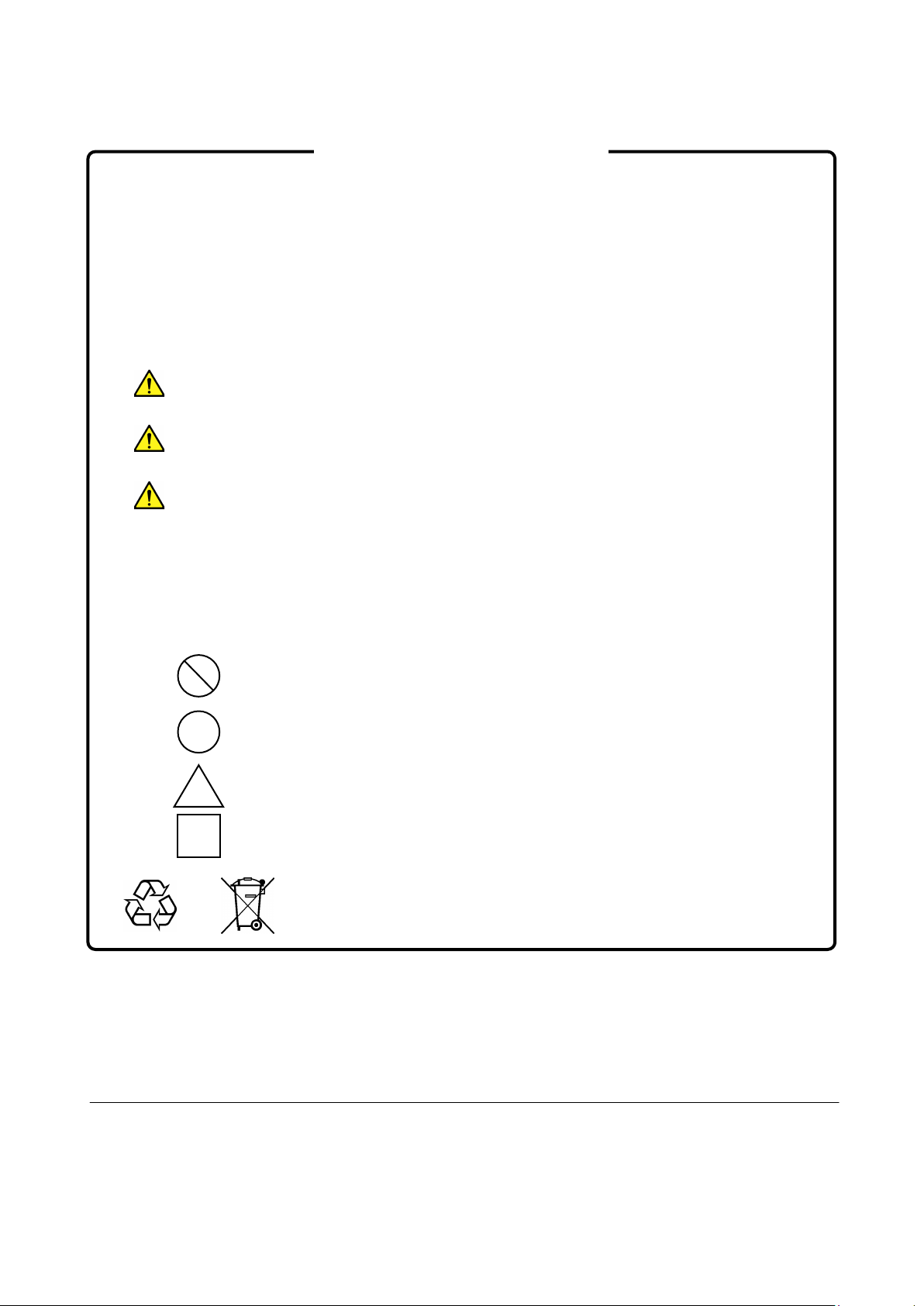
Safety Symbols
To prevent the risk of personal injury or loss related to equipment malfunction, Anritsu Corporation uses the
following safety symbols to indicate safety-related information. Ensure that you clearly understand the meanings of
the symbols BEFORE using the equipment. Some or all of the following symbols may be used on all Anritsu
equipment. In addition, there may be other labels attached to products that are not shown in the diagrams in this
manual.
Symbols used in manual
This indicates a very dangerous procedure that could result in serious injury or
death if not performed properly.
This indicates a hazardous procedure that could result in serious injury or death if
not performed properly.
This indicates a hazardous procedure or danger that could result in light-to-severe
injury, or loss related to equipment malfunction, if proper precautions are not taken.
Safety Symbols Used on Equipment and in Manual
The following safety symbols are used inside or on the equipment near operation locations to provide information
about safety items and operation precautions. Ensure that you clearly understand the meanings of the symbols and
take the necessary precautions BEFORE using the equipment.
This indicates an obligatory safety precaution. The obligatory operation is
This indicates a warning or caution. The contents are indicated symbolically in or
This indicates a note. The contents are described in the box.
These indicate that the marked part should be recycled.
This indicates a prohibited operation. The prohibited operation is indicated
symbolically in or near the barred circle.
indicated symbolically in or near the circle.
near the triangle.
MS9740A
Optical Spectrum Analyzer
Remote Control Operation Manual
15 December 2009 (First Edition)
23 June 2014 (10th Edition)
Copyright © 2009-2014, ANRITSU CORPORATION.
All rights reserved. No part of this manual may be reproduced without the prior written permission of the
publisher.
The contents of this manual may be changed without prior notice.
Printed in Japan
Page 3

iii
This product and its manuals may require an Export License/Approval by
the Government of the product's country of origin for re-export from your
coun
Before re-exporting the product or manuals, please contact us to confirm
whet
When you dispose of export-controlled items, the products/manuals need
to be broken/shredded so as not to be unlawfully used for military purpose.
Notes On Export Management
try.
her they are export-controlled items or not.
Page 4

iv
Page 5

I
About This Manual
This operation manual how to perform remote control of the MS9740A
Optical Spectrum Analyzer.
This operation manual assumes that:
the reader has already read the “MS9740A Optical Spectrum Analyzer
•
Operation Manual” and the
Remote Control Operation Manual
the reader can create C or Basic program.
•
Refer to the
to connect the power and peripheral equipment, for the panel operations,
and the maintenance procedures.
This manual is configured by the following structures: Chapter 1,
Chapter 2, Chapter 3, Chapter 4, and Appendix A to E. Read Chapter
1and 2 before using the MS9740A. For Chapter 3 or later, read them as
needed.
MS9740A Optical Spectrum Analyzer (M-W3328AE)
MS9740A Optical Spectrum Analyzer
.
for how
Chapter 1 Outline
This chapter explains the introduction and main uses for remote control
and technical terms used in this manual.
Chapter 2 Before Use
This chapter contains the following information you should read before
performing remote control of MS9740A: how to perform setup of
MS9740A, how to connect cables, message format, register structure, and
synchronous control.
Chapter 3 Sample Program
This chapter explains the sample program operating by Visual C++.
Chapter 4 Message Details
This section explains the remote command messages and rules.
Appendix A to E
These appendixes are reference materials when using the remote control.
Page 6

II
Table of Contents
About This Manual ....................................... I
Chapter 1 Outline ......................................... 1-1
1.1 About Remote Control .................................................. 1-2
1.2 Main Uses for Remote Control ..................................... 1-3
1.3 Glossary ........................................................................ 1-4
Chapter 2 Before Use .................................. 2-1
2.1 Preparing Equipment .................................................... 2-2
2.2 Connecting Equipment ................................................. 2-4
2.3 Setting Interface ............................................................ 2-7
2.4 Checking Connection .................................................. 2-10
2.5 Message Format ......................................................... 2-11
2.6 Checking Instrument Status ........................................ 2-13
2.7 Controlling Message Sync .......................................... 2-19
Chapter 3 Sample Program ......................... 3-1
3.1 Executing Sample Programs ........................................ 3-2
3.2 Example 1: Adjusting Optical System ........................... 3-6
3.3 Example 2: Measuring Center Wavelength and
Spectrum Width ............................................................ 3-8
3.4 Example 3: Reading Trace Data................................. 3-10
Chapter 4 Message Details .......................... 4-1
4.1 Description of Message Explanations .......................... 4-2
4.2 Correspondence between Panel Operation and
Message ....................................................................... 4-3
4.3 Message Function Category ....................................... 4-14
4.4 Device Message Details ............................................. 4-18
Page 7

III
Appendix A Changes from MS9710C ........ A-1
Appendix B Message Codes ...................... B-1
Appendix C BASIC Sample Program ........ C-1
Appendix D Sample Program without VISA D-1
Appendix E Bibliography ........................... E-1
Index .......................................................... Index-1
1
2
3
4
Appendix
Index
Page 8

IV
Table of Command
*CLS [Clear Status] ............................................................................................................. 4-18
*ESE [Event Status Enable] ................................................................................................ 4-19
*ESR [Standard Event Status Register] .............................................................................. 4-20
*IDN [Identification] .............................................................................................................. 4-20
*OPC [Operation Complete] ................................................................................................ 4-21
*OPT [Option Identification Query] ...................................................................................... 4-21
*RST [Reset] ....................................................................................................................... 4-22
*SRE [Service Request Enable] .......................................................................................... 4-22
*STB [Status Byte] ............................................................................................................... 4-23
*TST [Self-Test Query] ........................................................................................................ 4-23
*WAI [Wait to Continue]....................................................................................................... 4-23
ALIN [Auto Alignment] ......................................................................................................... 4-24
ANA [Spectrum Analysis] .................................................................................................... 4-25
ANA ENV [Spectrum Analysis (Envelope)] ......................................................................... 4-26
ANA NDB [Spectrum Analysis (NDB)] ................................................................................ 4-26
ANA OFF [Spectrum Analysis OFF] .................................................................................... 4-27
ANA PWR [Spectrum Analysis (Spectrum Power)] ............................................................ 4-27
ANA RMS [Spectrum Analysis (RMS)] ................................................................................ 4-28
ANA SMSR [Spectrum Analysis (SMSR)] ........................................................................... 4-29
ANA THR [Spectrum Analysis (THR)] ................................................................................. 4-29
ANAR [Spectrum Analysis Result] ...................................................................................... 4-30
AOFS [Auto Offset] .............................................................................................................. 4-31
AP [Application] ................................................................................................................... 4-32
AP AMP [Application (Optical Amp)] ................................................................................... 4-33
AP AMP,CAL [Application (Optical AMP Resolution Calibration)] ...................................... 4-34
AP AMP,MSL [Application (Optical AMP Memory Select)] ................................................. 4-35
AP AMP,PASE [Application (Optical AMP Pase)] ............................................................... 4-36
AP AMP,PIN [Application (Optical AMP Pin)] ..................................................................... 4-36
AP AMP,POUT [Application (Optical AMP Pout)] ............................................................... 4-37
AP AMP,PRM [Application (Optical AMP Parameter)] ........................................................ 4-38
AP AMP2 [Application (Optical Amp Multi Channel)] .......................................................... 4-40
AP AMP2,ASE [Application (Optical AMP Multi Channel ASE Detection Type)]................ 4-41
AP AMP2,ASE,AREA [Application (Optical AMP Multi Channel ASE Area Parameter)] ... 4-42
AP AMP2,ASE,AREA,FUNC [Application
(Optical AMP Multi Channel ASE Fitting Curve)] ...................................................... 4-43
AP AMP2,ASE,POINT [Application (Optical AMP Multi Channel ASE Point)] .................... 4-44
AP AMP2,MSL [Application (Optical AMP Multi Channel Memory Select)] ........................ 4-45
AP AMP2,OBPF [Application (Optical AMP Multi Channel Opt. Band Pass Filter)] ........... 4-46
AP AMP2,PIN [Application (Optical AMP Multi Channel Pin)] ............................................ 4-47
AP AMP2,POUT [Application (Optical AMP Multi Channel Pout)] ...................................... 4-47
AP AMP2,PRM [Application (Optical AMP Multi Channel Parameter)] .............................. 4-48
Page 9

V
AP AMP2,SLV [Application (Optical AMP Multi Channel Slice Level)] ............................... 4-49
AP AMP2,STHR [Application (Optical AMP Multi Channel Search Threshold)] ................. 4-49
AP AMP2,WL [Application (Optical AMP Multi Channel Wavelength Detection Type)] ..... 4-50
AP DFB [Application (DFB-LD)] .......................................................................................... 4-51
AP DFB,NDW [Application (DFB-LD ndB Width)] ............................................................... 4-52
AP DFB,SRES [Application (DFB-LD Search Resolution)] ................................................. 4-53
AP FP [Application (FP-LD)] ............................................................................................... 4-53
AP LD [Application (LD Module)] ........................................................................................ 4-54
AP LD,K [Application (LD Module K)] .................................................................................. 4-55
AP LD,NDW [Application (LD Module ndB Width)] ............................................................. 4-55
AP LD,NNRMZ [Application (LD Module Noise Normalization)] ......................................... 4-56
AP LD,NOISE [Application (LD Module Noise Detection Type)] ........................................ 4-57
AP LD,NOISE,AREA [Application (LD Module Noise Area Parameter)] ............................ 4-58
AP LD,NOISE,AREA,CH [Application (LD Module Noise Channel Area Parameter)] ........ 4-59
AP LD,NOISE,AREA,FUNC [Application (LD Module Noise Fitting Curve)] ...................... 4-60
AP LD,NOISE,AREA,USER [Application
(LD Module Noise User Specify Area Parameter)] ................................................... 4-61
AP LD,NOISE,POINT [Application (LD Module Noise Point)]............................................. 4-62
AP LD,NP [Application (LD Module Noise Position)] .......................................................... 4-63
AP LD,NT [Application (LD Module Noise Type)] ............................................................... 4-64
AP LD,SIGNAL,LV [Application (LD Module Signal Level)] ................................................ 4-65
AP LD,SIGNAL,SL [Application (LD Module Signal Level)] ................................................ 4-66
AP LD,SIGNAL,WL [Application (LD Module Signal Wavelength)] .................................... 4-67
AP LD,SMSR [Application (LD Module SMSR Parameter)]................................................ 4-68
AP LD,SRES [Application (LD Module Search Resolution)] ............................................... 4-68
AP LD,THR [Application (LD Module Slice Level)] ............................................................. 4-69
AP LED [Application (LED)] ................................................................................................ 4-69
AP OFF [Application OFF] .................................................................................................. 4-70
AP PMD [Application (PMD)] .............................................................................................. 4-70
AP WDM [Application (WDM)] ............................................................................................ 4-71
AP WDM,MPK [Application (WDM MultiPeak)] ................................................................... 4-72
AP WDM,NNRMZ [Application (WDM Noise Normalization)] ............................................. 4-72
AP WDM,NOISE [Application (WDM Noise Detection Type)] ............................................. 4-73
AP WDM,NOISE,AREA [Application (WDM Noise Area Parameter)] ................................ 4-74
AP WDM,NOISE,AREA,CH [Application (WDM Noise Channel Area Parameter)] ............ 4-74
AP WDM,NOISE,AREA,FUNC [Application (WDM Noise Fitting Curve)] .......................... 4-75
AP WDM,NOISE,AREA,USER [Application (WDM Noise User Specify Area Parameter)] 4-76
AP WDM,NOISE,POINT [Application (WDM Noise Point)] ................................................. 4-77
AP WDM,PKT [Application (WDM PeakType)] ................................................................... 4-78
AP WDM,REL [Application (WDM Relative)] ...................................................................... 4-78
AP WDM,SIGNAL,LV [Application (WDM Signal Level)] .................................................... 4-79
AP WDM,SIGNAL,WL [Application (WDM Signal Wavelength)]......................................... 4-80
AP WDM,SLV [Application (WDM Slice Level)] .................................................................. 4-80
AP WDM,SNR [Application (WDM SNR)] ........................................................................... 4-81
1
2
3
4
Appendix
Index
Page 10

VI
AP WDM,TBL [Application (WDM Table)] ........................................................................... 4-83
AP WDM,TCL [Application (WDM ThresholdCutLevel)] ..................................................... 4-84
AP WFIL [Application (WDM Filter)] .................................................................................... 4-85
AP WFIL,BWCL [Application (WDM Filter BW/Pass Band)] ............................................... 4-86
AP WFIL,CHDT [Application (WDM Filter Channel Detection)] .......................................... 4-87
AP WFIL,LVL [Application (WDM Filter Channel Detection)].............................................. 4-88
AP WFIL,RPS [Application (WDM Filter Ripple Span] ........................................................ 4-88
AP WFIL,SLV [Application (WDM Filter Slice Level] ........................................................... 4-89
AP WFIL,STHR [Application (WDM Filter Search Threshold)] ........................................... 4-89
AP WFIL,TCL [Application (WDM Filter Threshold Cut Level)]........................................... 4-90
APR [Application Result] ..................................................................................................... 4-91
APR AMP2,TBL [Application Result (Optical Amp Multi Channel Application)].................. 4-98
APR DFBNDW [Application Result (DFB-LD ndB Width)] .................................................. 4-99
APR LDNDW [Application Result (LD Module ndB Width)] .............................................. 4-100
APR LDSBCO [Application Result (LD Module Stop Band and Center Offset)] ............... 4-101
APR LDSNR [Application Result (LD Module SNR)] ........................................................ 4-102
APR MPKC [Application Result (Multi Peak Counter)] ..................................................... 4-103
APR WDM [Application Result (WDM Application)] .......................................................... 4-103
APR WDM,MPK [Application Result (WDM Application MultiPeak Display)] ................... 4-104
APR WDM,REL [Application Result (WDM Application Relative Display)] ....................... 4-105
APR WDM,SNR [Application Result (WDM Application SNR Display)] ............................ 4-106
APR WDM,SNR,GAV [Application Result (WDM Application SNR Display GAV)] .......... 4-107
APR WDM,TBL [Application Result (WDM Application Table Display)] ........................... 4-108
ARED [Actual Resolution Data] ......................................................................................... 4-108
ARES [Actual Resolution] ................................................................................................. 4-109
ATT [Optical Attenuator] .................................................................................................... 4-109
AUT [Auto Measure] .......................................................................................................... 4-110
AVS [Sweep Average] ....................................................................................................... 4-110
AVT [Point Average] .......................................................................................................... 4-111
BUZ [Buzzer] ..................................................................................................................... 4-111
CNT [Center Wavelength] ................................................................................................. 4-112
COLOR [Image Color Setting] ........................................................................................... 4-112
CPCOPYDAT [Copy Image Data] ..................................................................................... 4-113
CPCSV [Copy CSV Data] ................................................................................................. 4-113
CPSYSINFO [Copy System Information] .......................................................................... 4-114
CPXML [Copy XML Data] ................................................................................................. 4-114
DBA [Memory Data A] ....................................................................................................... 4-115
DBB [Memory Data B] ....................................................................................................... 4-115
DBC [Memory Data C]....................................................................................................... 4-115
DBD [Memory Data D]....................................................................................................... 4-115
DBE [Memory Data E] ....................................................................................................... 4-115
DBF [Memory Data F] ....................................................................................................... 4-115
DBG [Memory Data G] ...................................................................................................... 4-115
DBH [Memory Data H]....................................................................................................... 4-115
Page 11

VII
DBI [Memory Data I] .......................................................................................................... 4-115
DBJ [Memory Data J] ........................................................................................................ 4-115
DCA [Data Condition Trace A] .......................................................................................... 4-116
DCB [Data Condition Trace B] .......................................................................................... 4-116
DCC [Data Condition Trace C] .......................................................................................... 4-116
DCD [Data Condition Trace D] .......................................................................................... 4-116
DCE [Data Condition Trace E] .......................................................................................... 4-116
DCF [Data Condition Trace F] ........................................................................................... 4-116
DCG [Data Condition Trace G] ......................................................................................... 4-116
DCH [Data Condition Trace H] .......................................................................................... 4-116
DCI [Data Condition Trace I] ............................................................................................. 4-116
DCJ [Data Condition Trace J] ........................................................................................... 4-116
DELCOPYDAT [Delete Image Data] ................................................................................. 4-117
DELCSV [Delete CSV Data] ............................................................................................. 4-117
DELM [Delimiter] ............................................................................................................... 4-118
DELSYSINFO [Delete System Information] ...................................................................... 4-118
DELXML [Delete XML Data] ............................................................................................. 4-119
DMA [Memory Data A] ...................................................................................................... 4-120
DMB [Memory Data B] ...................................................................................................... 4-120
DMC [Memory Data C] ...................................................................................................... 4-120
DMD [Memory Data D] ...................................................................................................... 4-120
DME [Memory Data E] ...................................................................................................... 4-120
DMF [Memory Data F] ....................................................................................................... 4-120
DMG [Memory Data G]...................................................................................................... 4-120
DMH [Memory Data H] ...................................................................................................... 4-120
DMI [Memory Data I] ......................................................................................................... 4-120
DMJ [Memory Data J]........................................................................................................ 4-120
DMK [ΔMarker] .................................................................................................................. 4-121
DPS [Dip Search] .............................................................................................................. 4-122
DQA [Memory Data A]....................................................................................................... 4-123
DQB [Memory Data B]....................................................................................................... 4-123
DQC [Memory Data C] ...................................................................................................... 4-123
DQD [Memory Data D] ...................................................................................................... 4-123
DQE [Memory Data E]....................................................................................................... 4-123
DQF [Memory Data F] ....................................................................................................... 4-123
DQG [Memory Data G] ...................................................................................................... 4-123
DQH [Memory Data H] ...................................................................................................... 4-123
DQI [Memory Data I] ......................................................................................................... 4-123
DQJ [Memory Data J] ........................................................................................................ 4-123
DRG [Dynamic Range Mode] ............................................................................................ 4-124
DSP [Display Mode] .......................................................................................................... 4-124
EMK [Erase Marker] .......................................................................................................... 4-124
EOV [Erase Overlap] ......................................................................................................... 4-124
ERR [Error] ........................................................................................................................ 4-125
1
2
3
4
Appendix
Index
Page 12

VIII
ESE2 [Extended Event Status Enable Register2] ............................................................. 4-125
ESE3 [Extended Event Status Enable Register3] ............................................................. 4-125
ESR2 [Extended Event Status Enable Register2] ............................................................ 4-126
ESR3 [Extended Event Status Enable Register3] ............................................................ 4-126
FML [Formula] ................................................................................................................... 4-127
GHC [Get Binary Data of Image Data] .............................................................................. 4-128
ITM [Interval Time] ............................................................................................................ 4-129
LISTCOPYDAT [List Image Data] ..................................................................................... 4-130
LISTCSV [List CSV Data] .................................................................................................. 4-131
LISTSYSINFO [List System Information] .......................................................................... 4-132
LISTXML [List XML Data] .................................................................................................. 4-133
LLV [Linear Scale] ............................................................................................................. 4-134
LOFS [Level Offset] ........................................................................................................... 4-135
LOG [Log Scale] ................................................................................................................ 4-135
LVS [Level Scale] .............................................................................................................. 4-136
MDM [Modulation Mode] ................................................................................................... 4-136
MKA [Wavelength Marker A] ............................................................................................. 4-137
MKB [Wavelength Marker B] ............................................................................................. 4-137
MKC [Level Marker C] ....................................................................................................... 4-138
MKD [Level Marker D] ....................................................................................................... 4-139
MKV [Marker Value Wavelength/Frequency Select] ......................................................... 4-139
MMM [Multimode fiber Mode] ............................................................................................ 4-140
MOD [Measure Mode] ....................................................................................................... 4-140
MPT [Sampling Points] ...................................................................................................... 4-140
MVCOPYDAT [Move Image Data] .................................................................................... 4-141
MVCSV [Move CSV Data] ................................................................................................. 4-141
MVSYSINFO [Move System Information] ......................................................................... 4-142
MVXML [Move XML Data] ................................................................................................. 4-142
OPT [Light Output] ............................................................................................................ 4-143
PKC [Peak→Center] ......................................................................................................... 4-143
PKL [Peak→Level] ............................................................................................................ 4-143
PKS [Peak Search] ............................................................................................................ 4-144
PMOD [Format of Image File] ........................................................................................... 4-145
PPC [Peak to Peak Calculation] ........................................................................................ 4-145
PPMK [Peak to Peak Maker] ............................................................................................. 4-146
PRE [Preset] ...................................................................................................................... 4-146
PRINT [Save Image Data] ................................................................................................. 4-147
PRTCOPYDAT [Protect Image Data] ................................................................................ 4-148
PRTCSV [Protect CSV Data] ............................................................................................ 4-149
PRTSYSINFO [Protect System Information] ..................................................................... 4-150
PRTXML [Protect XML Data] ............................................................................................ 4-151
PWR [Power Monitor] ........................................................................................................ 4-151
PWRR [Power Monitor Result] .......................................................................................... 4-152
RCAL [Resolution Calibration] .......................................................................................... 4-152
Page 13

IX
RCXML [Recall XML Data] ................................................................................................ 4-153
RES [Resolution] ............................................................................................................... 4-153
RLV [Reference Level] ...................................................................................................... 4-154
SMD [Storage Mode] ......................................................................................................... 4-154
SMT [Smooth] ................................................................................................................... 4-155
SOFTVER [Software Version] ........................................................................................... 4-155
SPC [Spectrum Mode]....................................................................................................... 4-155
SPN [Span Wavelength] ................................................................................................... 4-156
STHR [Search Threshold] ................................................................................................. 4-156
STHRS [Search Threshold Set] ........................................................................................ 4-156
SRT [Repeat Sweep]......................................................................................................... 4-157
SSI [Single Sweep] ............................................................................................................ 4-157
SST [Sweep Stop] ............................................................................................................. 4-157
STA [Start Wavelength] ..................................................................................................... 4-157
STO [Stop Wavelength]..................................................................................................... 4-158
SVCSV [Save CSV Data] .................................................................................................. 4-158
SVCSVA [Save CSV All Data] .......................................................................................... 4-159
SVXML [Save XML Data] .................................................................................................. 4-160
SYS [Application Switch] ................................................................................................... 4-161
SYSINFO [System Information] ........................................................................................ 4-162
TDL [Ext-Trigger Delay Time] ........................................................................................... 4-163
TER [Title Erase] ............................................................................................................... 4-163
TMD [Trace Display] .......................................................................................................... 4-163
TMK [Trace Marker] .......................................................................................................... 4-164
TRM [Terminator] .............................................................................................................. 4-165
TSL [Trace Select] ............................................................................................................. 4-165
TTL [Title] .......................................................................................................................... 4-166
TTP [Trace Type] .............................................................................................................. 4-166
VBW [Video Band Width] .................................................................................................. 4-167
WCAL [Wavelength Calibration] ........................................................................................ 4-168
WDP [Wavelength Display] ............................................................................................... 4-168
WOFS [Wavelength Offset] ............................................................................................... 4-169
WSS [Wavelength Start and Stop] .................................................................................... 4-169
ZCAL [Zero Calibration]..................................................................................................... 4-170
ZMK [Zone Marker] ........................................................................................................... 4-171
ZMK ERS[Zone Marker (Erase)] ....................................................................................... 4-171
ZMK SPN[Zone Marker (Span)] ........................................................................................ 4-172
ZMK WL[Zone Marker (Wavelength)] ............................................................................... 4-172
ZMK ZOOM [Zone Marker(Zoom In/Out)] ......................................................................... 4-173
1
2
3
4
Appendix
Index
Page 14

X.
Page 15

1-1
Outline
Chapter 1 Outline
This chapter explains the outline of the remote control, main uses, and
glossary.
1.1
About Remote Control .................................................. 1-2
1.2 Main Uses for Remote Control ..................................... 1-3
1.3 Glossary ........................................................................ 1-4
1
Page 16

Chapter 1 Outline
1-2
1.1 About Remote Control
The remote control function sends commands via the communications
interface from the remote control PC to set the measuring instrument
and read the measurement results and measuring instrument conditions.
The MS9740A Optical Spectrum Analyzer (hereafter, MS9740A) supports
the Ethernet interface and GPIB interface. (When the option 001 is
installed, the GPIB interface can be used.)
The character strings for controlling the MS9740A are called program
messages; the responses from it are called response messages. Program
and response messages are both composed of strings of ASCII code.
Program messages are divided into two types: command messages for
executing settings at the MS9740A, and query messages for reading data
from it.
For example, the following command sets the measurement wavelength
Center to 1560 nm:
CNT 1560
A command for reading data from this instrument is called a query
message. A query command has the question symbol (?) appended to the
string. For example, sending the following command queries the Span set
at the instrument.
SPN?
The controller PC receives the following response against the query
message from the instrument.
>10
This response message indicates that the Span setting is 10 nm.
The front-panel displays and Local key operations are still enabled even
when the instrument is being remotely controlled. This state calls the
panel lock. To disable this panel lock state, press the
Local
key.
Page 17
1.2 Main Uses for Remote Control
1-3
Outline
1.2 Main Uses for Remote Control
Temperature
tank
Laser Diode
Power
Optical Spectrum Analyzer
PC
Model: Sample-001 Forward Current = 50 mA
–10
1308.1
0.93
0
1309.1
0.92
10
1310.0
0.94
20
1311.0
0.95
30
1311.9
0.94
40
1312.9
0.95
50
1313.8
0.96
The main uses for remote control are listed below.
Automating Measurements
Instead of key-panel operations, measurement can be automated by
controlling the instrument by executing programs.
Remote Control of Instruments
Measuring instruments at remote locations can be controlled over
communications lines to collect measurement data.
Controlling Multiple Instruments
The characteristics of multiple DUTs can be measured simultaneously by
remote control of multiple instruments.
1
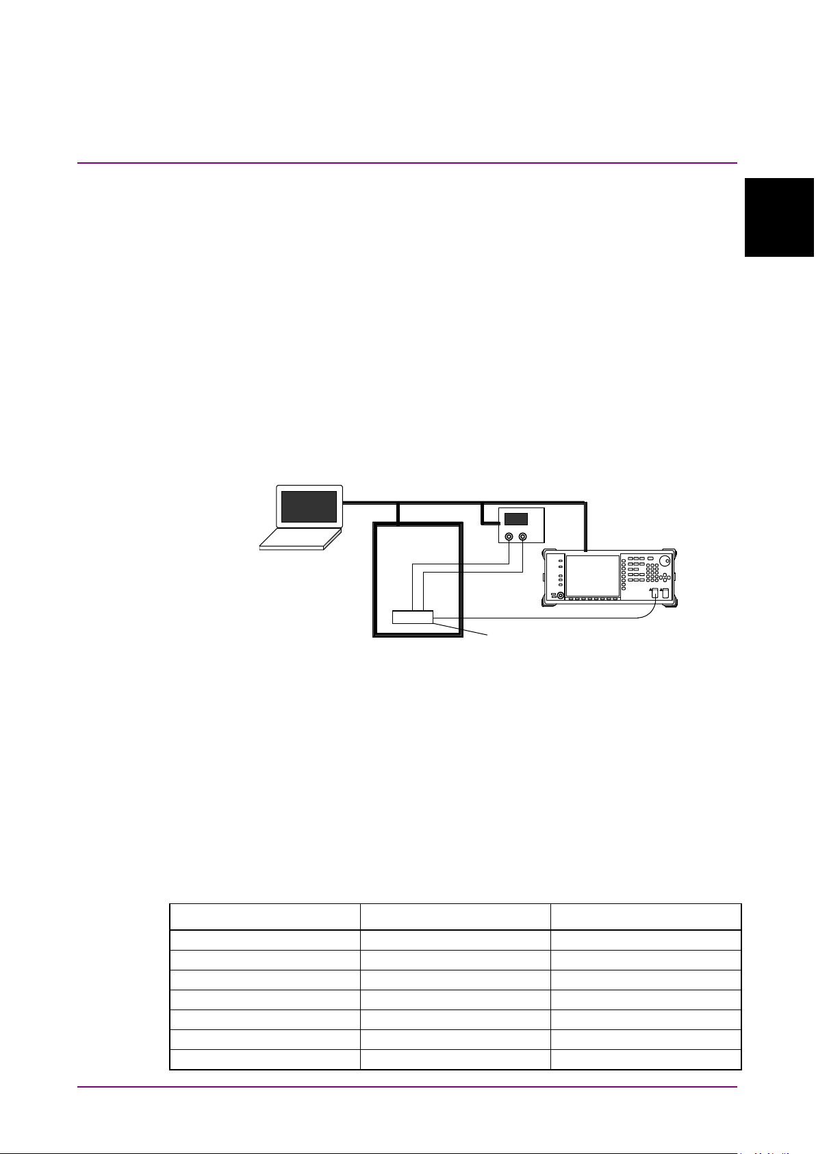
Figure 1.2-1 Example of Controlling Multiple Instruments
Figure 1.2-1 shows an example of controlling multiple instruments. In
this example, the wavelength characteristics of an LD are measured with
changes in temperature and LD current. The power supply current and
temperature chamber temperature are controlled remotely from the PC
and the LD wavelength and spectrum data are read by the spectrum
analyzer. Table 1.2-1 shows the LD characteristics obtained from the
spectrum data for the set temperatures and current.
Table 1.2-1 Measurement Example of LD Measured with Changes in Temperature
Temperature (C°) Wavelength (nm) Spectral Width RMS (nm)
Page 18

Chapter 1 Outline
1-4.
CR
Carriage Return
ESER
Event Status Enable Register
ESR
Event Status Register
GPIB
General Purpose Interface Bus
IEC
International Electrotechnical Commission
IEEE
Institute of Electrical and Electronics
Engineers
LAN
Local Area Network
LF
Line Feed
MAV
Message Available summary
MSS
Master Summary Status
SESER
Standard Event Status Enable Register
SESR
Standard Event Status Register
SRER
Service Request Enable Register
STB
Status Byte
VISA
Virtual Instrument Software Architecture
1.3 Glossary
Table 1.3-1 indicates what abbreviations are used in this operation
manual.
Table 1.3-1 Abbreviation
Abbreviation Formal name
Page 19

2-1
Before Use
Chapter 2 Before Use
This chapter explains the preparations for using remote control.
Preparing Equipment .................................................... 2-2
2.1
2.2 Connecting Equipment ................................................. 2-4
2.2.1 Connecting Ethernet ......................................... 2-4
2.2.2 Connecting GPIB .............................................. 2-5
2.3 Setting Interface ............................................................ 2-7
2.3.1 Setting Ethernet ................................................ 2-7
2.3.2 Setting GPIB ..................................................... 2-9
2.4 Checking Connection .................................................. 2-10
2.5 Message Format ......................................................... 2-11
2.6 Checking Instrument Status ........................................ 2-13
2.6.1 Register Structure ........................................... 2-13
2.6.2 Status Byte Register ....................................... 2-15
2.6.3 Event Register ................................................ 2-16
2.7 Controlling Message Sync .......................................... 2-19
2
Page 20

Chapter 2 Before Use
2-2
2.1 Preparing Equipment
The following equipment is required to perform remote control.
PC
•
Ethernet interface
•
Ethernet cable
•
GPIB interface (when installing Option 001)
•
GPIB cable (when installing Option 001)
•
VISA
•
Program development tools
•
Ethernet Interface
Prepare the interface that conforms to the following specifications:
10BASE-T
100BASE-TX
1000BASE-T
Furthermore, use the cable corresponding to each specification.
GPIB Interface
Procure the GPIB interfaces that conform with IEEE 488.2.
VISA
When controlling the MS9740A remotely using the Ethernet port, a
*1
VISA
using NI-VISA™
VISA driver.
Although a license is generally required to use NI-VISA™, the licensed
NI-VISA™ driver is provided free-of-charge for use when performing
remote control*
option has been installed.
The NI-VISA™ driver can be downloaded from the NI website at:
http://sine.ni.com/psp/app/doc/p/id/psp-411
Be sure to comply with the NI license agreement for the usage and
license scope.
Be sure to uninstall the NI-VISA™ driver when disposing of the
MS9740A or transferring it to a third party, etc., or when ceasing to use
NI-VISA™.
*1: Although the NI-VISA™ driver itself can be downloaded
driver must be installed in the PC controller. We recommend
*2
from National Instruments™ (NI hereafter) as the
1,*2
of a MS9740A unit in which the MS9740A-001 GPIB
free-of-charge from the web, an implementation license is required
Page 21

2.1 Preparing Equipment
2-3
Before Use
for legal reasons if some requirements are not met. (Check the NI
web page for the detailed requirements.)
*2: If these requirements are not met, permission is not granted to use
NI hardware and software and an NI implementation license must
be purchased. However, since the MS9740A-001 GPIB option
incorporates NI hardware (GPIB ASIC), the NI-VISA™ driver can be
used free-of-charge.
Glossary of Terms:
● VISA: Virtual Instrument Software Architecture
I/O software specification for remote control of measuring instruments
using interfaces such as GPIB, Ethernet, USB, etc.
● NI-VISA™
World
standardized by the VXI Plug&Play Alliance.
Trademarks:
de facto
standard I/O software interface developed by NI and
2
● National Instruments™, NI™, NI-VISA™ and National Instruments
Corporation are all trademarks of National Instruments Corporation.
Program Development Tools
Prepare some tools for developing and running programs for performing
remote control. Refer to the VISA and Interface manuals for the
specifications required by the program development tools.
PC
The PC must be able to run the GPIB interface, VISA and program
development tools.
Page 22
Chapter 2 Before Use
2.2 Connecting Equipment
2.2.1 Connecting Ethernet
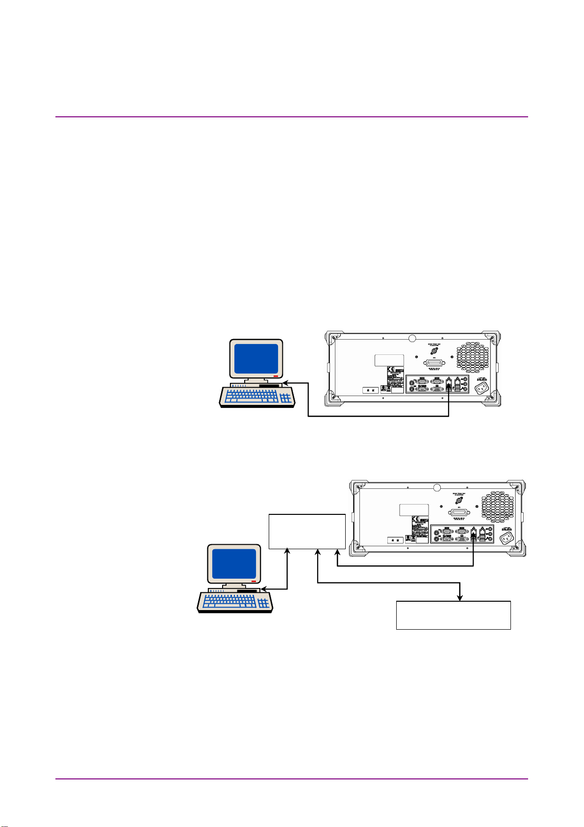
Connect the Ethernet connector on the rear-panel of the MS9740A and
external devices using LAN cables.
Use a LAN crossover cable to connect the MS9740A and an external
device. Use a network hub when connecting to multiple external devices.
Note:
Check the network settings of the MS9740A when connecting to
multiple external devices
Figure 2.2.1-1 Sample Connection with One External Device
PC
Connect using a LAN cross cable
PC
Network hub
Connect using a LAN
straight cable
External device
2-4
Figure 2.2.1-2 Sample Connection with Multiple External Devices
Note:
External devices may experience difficulty in communicating with
the MS9740A, depending on the status of communications between
them. A LAN crossover-cable connection is recommended to ensure
communication stability.
Page 23
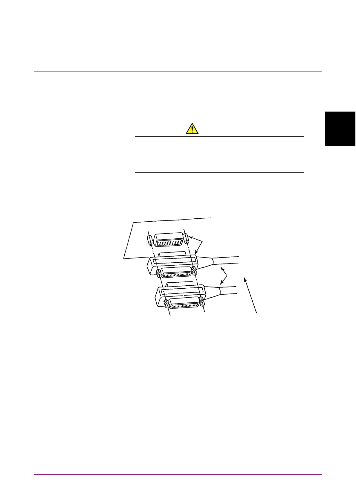
2.2.2 Connecting GPIB
Connect the GPIB connector on the rear panel of the MS9740A and an
external device using a GPIB cable.
2.2 Connecting Equipment
CAUTION
Be sure to connect the GPIB cable before turning power
on the MS9740A. Connecting it while the power is on may
damage internal circuits.
Up to 15 devices, including the external controller (PC), can be connected
to one MS9740A unit. Be sure to abide by the conditions shown below
when connecting devices.
GPIB connector
GPIB connector
2
Before Use
Total cable length: Up to 20 m
Cable length between devices: Up to 4 m
Number of devices that can be connected: Up to 15
Figure 2.2.2-1 GPIB Cable Connection 1
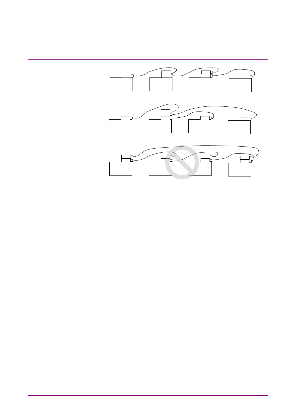
Connect cables without forming loops.
2-5
Page 24
Chapter 2 Before Use
2-6
(a) Daisy Chain
(b) Star
(c) Loop
Figure 2.2.2-2 GPIB Cable Connection 2
Page 25

2.3 Setting Interface
2-7
Before Use
2.3 Setting Interface
Control Panel
Network Connections
Local Area Connection
Properties
Internet
Protocol (TCP/IP)
Properties
Use the following IP Address
IP address
Subnet mask
Local Area Connection Properties
2.3.1 Setting Ethernet
Check the IP address and delimiter.
1. Press
2. Press
3. Open the dialog box to display the MS9740A address in the Ethernet
4. Set the terminator.
The terminator indicates the end of the sent command.
CR/LF: When two characters, ASCII code 13 (carriage return—CR)
and 10 (line feed—LF), received
LF: When one character, ASCII code 10 (line feed) , received
EOI: When signal received from GPIB signal line (End or Identity)
Connect a keyboard to the MS9740A, when changing the IP address.
1. Press the Windows key on the connected keyboard.
2. Click
3. The Control Panel window is displayed, and then double-click
F6
to display Config on the horizontal function keys.
f1 Interface Setting
setting IP address.
Select “CR/LF,” “LF,” or “None (EOI only)” for Terminator in the
Terminator Settings field.
.
.
.
2
4. Right-click
5. The Local Area Connection Properties dialog box is displayed.
On the Local Area Connection Properties dialog box,
6. Check
7. Enter
When creating a program to control this instrument, the IP address
input here is required.
8. Click OK
9. Click OK on the
and press
and
, and then click
.
.
.
.
.
Page 26
Chapter 2 Before Use
2-8
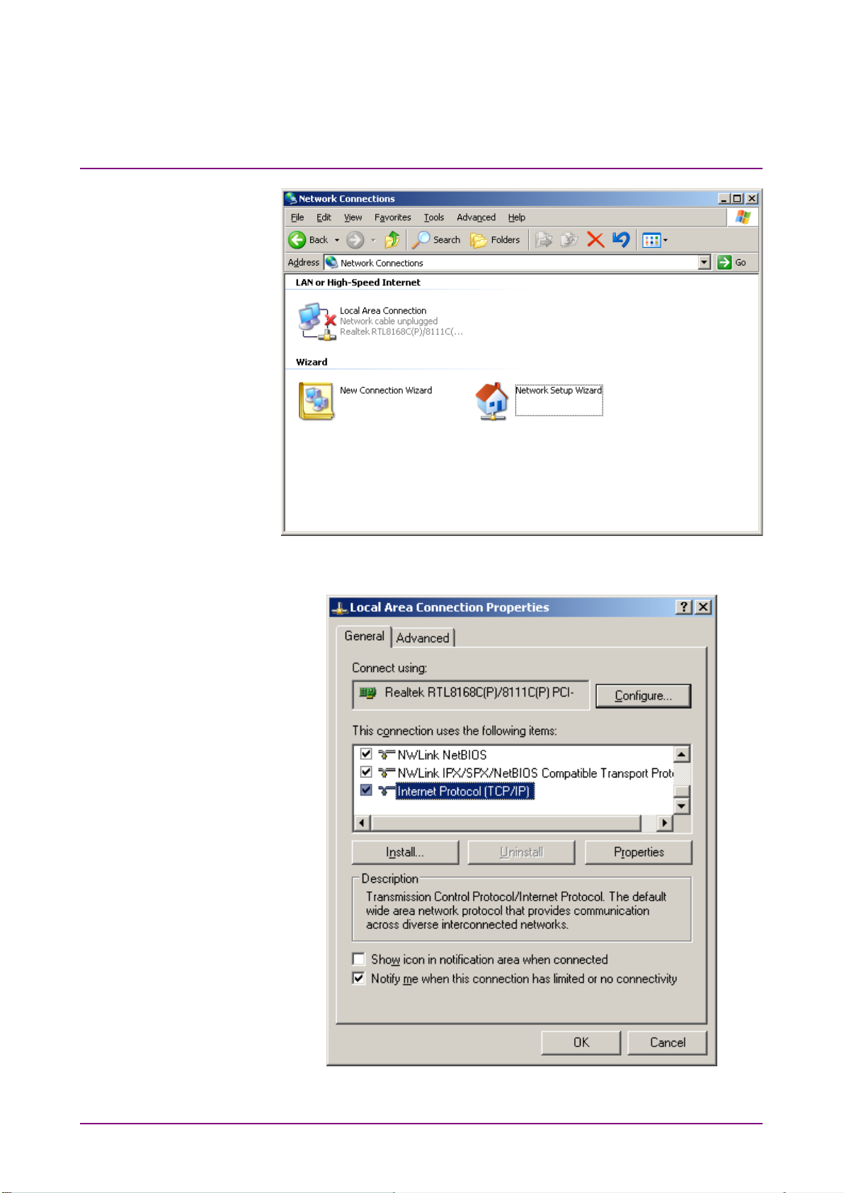
Figure 2.3.1-1 Network Connections Window
Figure 2.3.1-2 Local Area Connection Properties Dialog Box
Page 27
2.3 Setting Interface
2-9
Before Use
2
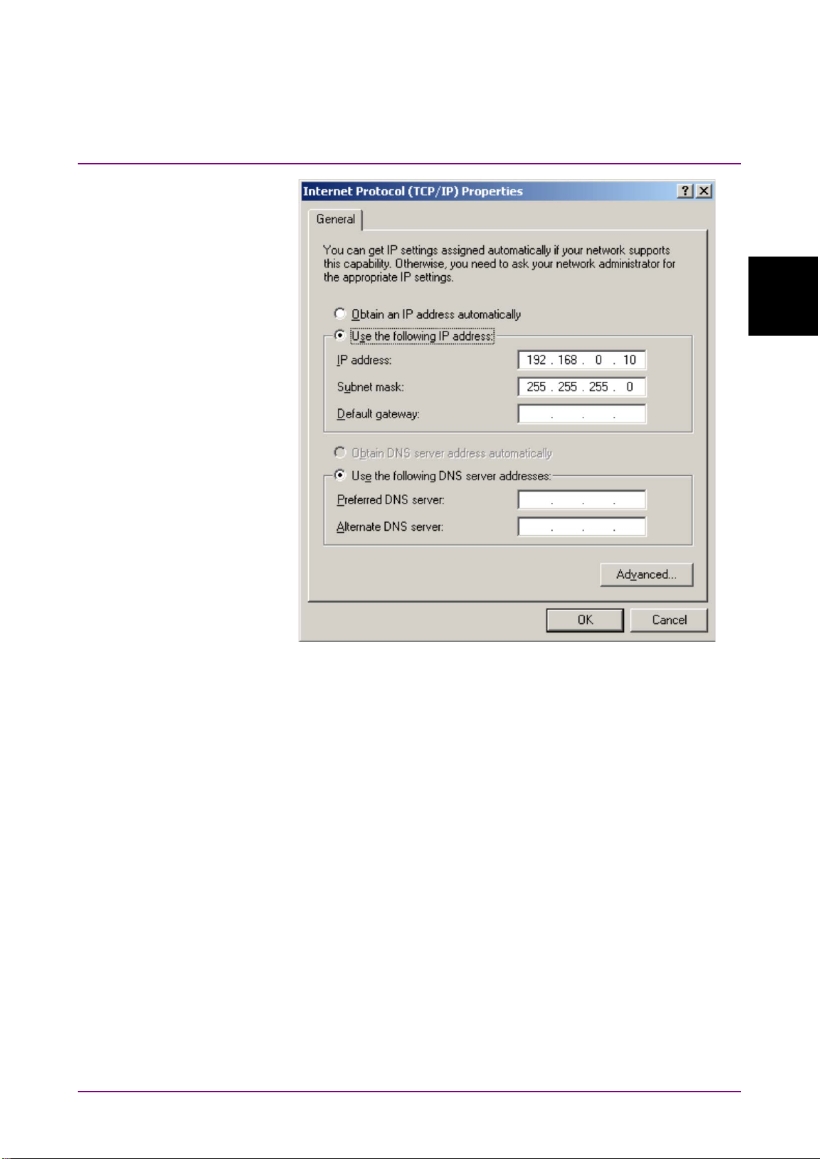
Figure 2.3.1-3 Internet Protocol (TCP/IP) Properties Dialog Box
2.3.2 Setting GPIB
Check the MS9740A GPB address and delimiter with the following
procedure.
1. Press F6 to display Config on the horizontal function keys.
2. Press
3. Open the dialog box. The MS9740A address is displayed in the GPIB
4. Set the GPIB address in the range from 1 to 30 using the arrow keys
5. Set the terminator of the response message.
f 1 Interface Setting
setting address.
or rotary knob.
Select “CR/LF,” “LF,” or “None (EOI only)” for Terminator in the
Terminator Settings field.
.
Page 28
Chapter 2 Before Use
2-10
Programs
Accessories
Command Prompt
2.4 Checking Connection
Check that the link between the PC and MS9740A has been established.
When using Ethernet:
1. Click
2. Click
3. Click
4. Input ping and the MS9740A IP address at the command prompt
screen.
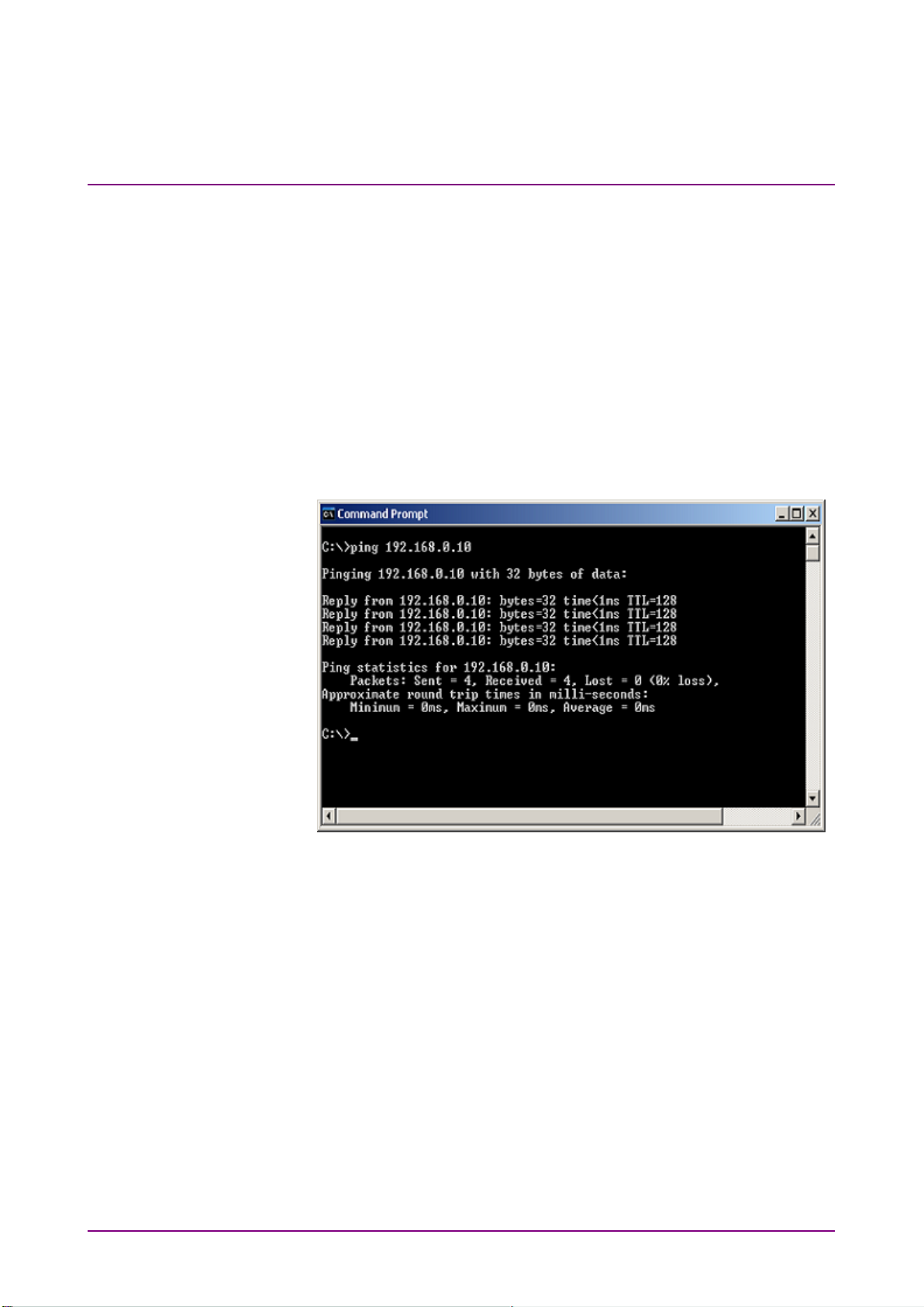
Figure 2.4-1 shows how to set the IP address to 192.168.0.10.
at the Windows Start menu.
.
.
Figure 2.4-1 Example of Ping Command
5. If “Request timed out” message is displayed, the link between the
PC and MS9740A has not been connected properly. Check that IP
address is correct and cable is connected properly.
When using GPIB
1. Install the software supplied with the GPIB interface.
2. Start the software.
For the software operation method, refer to the GPIB interface
operation manual.
3. Check the displayed instrument address.
Page 29

2.5 Message Format
2-11
Before Use
2.5 Message Format
Messages are composed of character strings for executing commands and
character strings indicating the message end. The later character strings
are set in 2.3 “Setting Interface”.
Messages are composed of the following types:
Program Messages
Messages sent from PC to instrument
These are composed of commands to set the instrument and queries
requesting sending of a response message.
Response Messages:
Messages sent from instrument to PC controller
These messages are composed of header and data parts separated by
more than a half width space.
The header is composed of alphanumeric characters and underbars while
the head string is alphabetic characters. However, common commands
defined by IEEE 488.2 have an asterisk (*) appended to the header string.
Both upper and lower-case alphabetic characters are supported.
Command with only header:
*RST
AUT
SSI
TER
2
Command with header and data:
Messages with multiple data use commas (,) to separate the data parts.
Example:
Queries have a question mark (?) appended to the header.
Example:
SPN 10
AVT OFF
AP WDM,SNR,HIGHER,1,ON
ZMK WL,1310,20
DMA?
ZMK? WL
AP? WDM,SNR
Page 30

Chapter 2 Before Use
2-12
When linking multiple program messages, separate the message using
semicolons (;).
Example:
The data format is character string data, numeric data, and binary data.
String data is ASCII code enclosed in quotation marks.
An example of the program message when inputting Model ANR-005 at
the title is shown below.
Example:
When using numeric data, input numeric values either as integers or
floating point representation. Each following example indicates the same
value.
Example:
For the binary data, the head string starts with a sign (#) and continues
with data after a numeric value indicating the data length.
The character after the sign (#) indicates the number of digits in the data
length.
The binary data follows the number indicating the data length.
Example:
CNT 1550 ; SSI ; *WAI ; DMA?
TTL ‘Model ANR-005’, TTL “Model ANR-005”
-90 -90.00 -9E1
1310 1310.0 1.31E3
0.0023 2.3E-4
#42002 an%*qe4445+\
4 digits 2002 bytes of binary data
Page 31
2.6 Checking Instrument Status
2-13
Before Use
2.6 Checking Instrument Status
Status Byte
Register
Send Queue
Standard event
Register / Enable register
Power On
Not used
Command Error
Execution Error
Device Dependent Error
Query Error
Not used
Operation Complete
Not used
Not used
Error Event
Register/Enable register
Not used
Not used
Not used
Not used
Not used
Meas Condition
PEAK/DIP
RES Uncal
End Event
Register/Enable register
Not used
Not used
Not used
Execution Error 1
Execution Error 2
Not used
Sweep End
Measurement End
Not used
MSS
ESB
MAV
Bit
7
6
5
4
3
2
1
0
Bit
7
6
5
4
3
2
1
0
Logical Sum
&
Bit
7
6
5
4
3
2
1
0
Bit
7
6
5
4
3
2
1
0
Logical Sum
&
Bit
7
6
5
4
3
2
1
0
Bit
7
6
5
4
3
2
1
0
Logical Sum
&
Bit
7
6
5
4
3
2
1
0
Bit
7
6
5
4
3
2
1
0
Logical Sum
&
Service request
Enable register
Service
Request
&: logical AND per bit
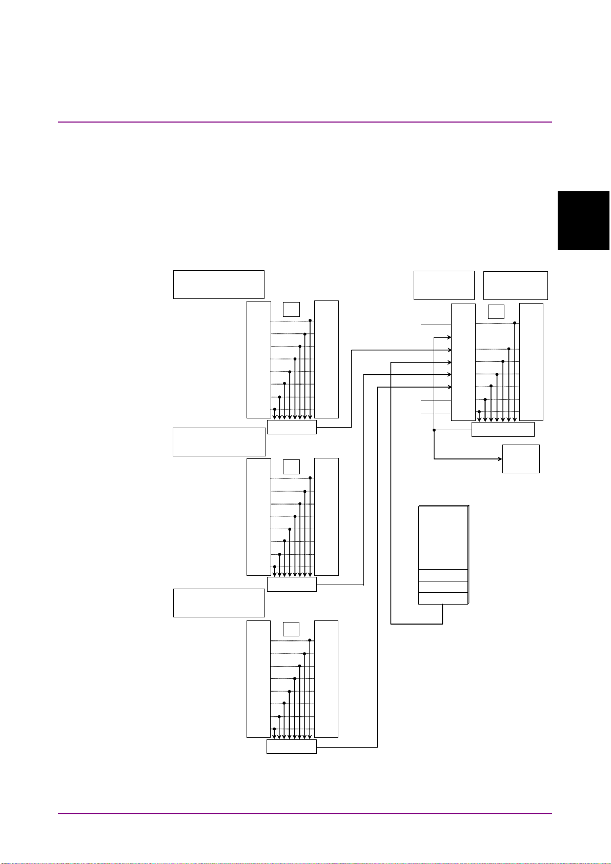
This instrument has registers indicating the status, such as errors and
command execution status. This section explains these registers.
2.6.1 Register Structure
Figure 2.6.1-1 shows the structure of the registers indicating the
instrument status.
2
Figure 2.6.1-1 Register Structure
Page 32

Chapter 2 Before Use
2-14
7
128 6 64
5
32
4
16 3 8
2
4
1 2 0
1
Each register uses 8-bit data. The register output values are the decimal
totals for each bit shown in Figure 2.6.1-1.
Table 2.6.1-1 Register Bit Decimal Conversion Values
Bit Decimal value
The service request enable register has a corresponding status byte
register. The logical product per bit of these two registers is obtained and
the logical sum of this result is output to the MSS (Master Summary
Status) bit. When the MSS bit is 1, the data report to the PC controller is
displayed on the equipment screen; when the MSS bit changes from 0 to
1, an interrupt is generated from the equipment to the PC controller.
This interrupt is called the service request.
Each standard event register (standard, error, end) has a corresponding
enable register. The logical product per bit of the event and enable
registers is obtained and the logical sum of this result is output to bit 5, 3
and 2 of the status byte register.
Page 33

2.6 Checking Instrument Status
2-15
Before Use
2.6.2 Status Byte Register
7
Not used; always 0
6
MSS (Master Summary Register)
request enable register.
5
This is the logical sum of each bit of the logical product
event enable register.
4
MAV (Message Available summary)
the output queue of this instrument
3
This is the logical sum of each bit of the logical product
of the error event register and event enable register.
2
This is the logical sum of each bit of the logical product
of the end event register and event enable register.
1
Not used; always 0
0
Not used; always 0
The meaning of each bit of the status byte register is shown in the
following table.
Table 2.6.2-1 Meaning of Status Byte Register
Bit Explanation
It is the logical sum of the bit 5 to 0, bit 7 logical
product of the status byte register and the service
of the standard event status register and standard
This is always 1 when there is a response message in
The following methods are used to read the status byte register.
Using common
•
Using GPIB serial poll (when Option 001 installed)
•
Read the GPIB interface manual for the serial poll method.
When using serial polling, even if bit 6 is 1, it becomes 0 after reading
once.
*SRE
The
reading the service request enable register for setting reading of the
status byte register. To output the status byte register data, set the bit
corresponding to the service request enable register to 1.
and
*STB?
command
*SRE?
common commands can be used for setting and
2
Bits 5, 3, and 2 of the status byte register can be set to 0 using the
common command.
*CLS
When
the send queue is cleared and bit 4 is set to 0.
is sent after a command or when a query is sent after
*CLS
*CLS
,
Page 34

Chapter 2 Before Use
2-16
7
Power-on
Becomes 1 at power-on and returns 0 when read.
6
Not used; always 0
5
Command Error
message with spelling error
4
Execution Error
be executed.
3
Device Dependent Error
and query errors.
2
Query Error
output queue data fails for some reason.
1
Not used; always 0
0
Operation Complete
after the *OPC command operation.
2.6.3 Event Register
Standard Event Status Register
The meaning of each bit of the standard event status register is listed in
the table below.
Table 2.6.3-1 Meaning of Standard Event Status Register
Bit Explanation
Becomes 1 when received undefined program message,
message that cannot executed according to syntax, or
Becomes 1 when received program message that cannot
Becomes 1 at errors other than command, execution
Becomes 1 when no data to read in output queue or
Becomes 1 when all command operation completed
Bit 7 to bit 0 of the standard event register can be read by the
command. The standard event register returns to 0 when read.
The standard event register enable register can be set and read using the
*ESE
the bit corresponding to the enable register to 1.
The standard event register can be set to 0 using the
and
*ESE?
commands. To output standard event register data, set
*CLS
*ESR?
command.
Page 35

2.6 Checking Instrument Status
2-17
Before Use
7
Not used; always 0
6
Not used; always 0
5
Not used; always 0
4
End Execution 1
and adjusting optical system operations completed.
3
End Execution 2
power monitor operations completed.
2
Not used; always 0
1
Sweep end
Become 1 when sweeping completed.
0
Measurement end
command to query end event register.
4
ALIN, AP AMP, CAL, RCAL, WCAL, ZCAL
3
PWR, SSI
1
SSI
0
ANA, AP (DFB|FP|LED|PMD|AMP|WDM|LD), AUT,
DPS, PKS, PPC
End Event Register
The meaning of each bit of the end event status register is listed in the
table below.
Table 2.6.3-2 Meaning of End Event Status Register
Bit Explanation
Becomes 1 when calibrating wavelength of resolution
Becomes 1 when sweep averaging or measuring with
Becomes 1 when one of the following commands has
been processed: Auto Measurement, analysis using
Analysis function, Peak/Dip Search processing,
analysis using Application function.
To execute multiple commands, send ESR2? for each
The commands for checking the completion of end event register
execution are shown below.
Table 2.6.3-3 Commands for Checking End Event Register Execution
2
End Event
Register Bit
The end event register can be read by the
The end event register enable register can be set and read using the
ESE2
and
corresponding to the enable register to 1.
The end event register can be set to 0 using the *CLS command.
The enable register of the end event register cannot be changed using
*CLS
.
Command
ESR2?
.
ESE2?
commands. To output end event register data, set the bit
Page 36

Chapter 2 Before Use
2-18
7
Not used; always 0
6
Not used; always 0
5
Not used; always 0
4
Not used; always 0
3
Not used; always 0
2
Meas-Condition
parameters
1
Peak/Dip
or dip search executed.
0
RES-Uncal
sweep width and sample count.
2
MPT, RES, CNT, SPN, STA, STO,
1
DPS, PKC, PKL, PKS
0
MPT, RES, SPN, STA, STO
Error Event Register
The meaning of each bit of the error event status register is listed in the
table below.
Table 2.6.3-4 Meaning of Error Event Status Register
Bit Explanation
Becomes 1 at mismatch between current measurement
condition parameters (Active trace measurement
conditions) and result measurement condition
Becomes 1 when level peak or dip not found when peak
Becomes 1 when resolution setting not appropriate for
The commands for checking the completion of error event register
execution are shown in Table 2.6.3-5.
Table 2.6.3-5 Commands for Checking Error Event Register Execution
Error Event
Register Bit
The error event register can be read by the
The error event register enable register can be set and read using the
ESE3
bit corresponding to the enable register to 1.
The error event register can be set to 0 using the
The enable register of the error event register cannot be changed using
*CLS
and
.
ESE3?
commands. To output error event register data, set the
Command
ESR3?
.
*CLS
command.
Page 37

2.7 Controlling Message Sync
2-19
Before Use
2.7 Controlling Message Sync
Time
Message received
SSI;Sweeping
PKS PEAK;
Peak search
detection
TMK?;
Save to marker data
output queu
e
Peak detected at this time point
There are two message types.
Synchronous message
This message cannot be executed with the next message at the same time
while executing the program message.
Asynchronous message
This message can be executed with the next sent message at the same
time while executing the program message. The followings are the
asynchronous messages for the MS9740A.
ALIN, ANA, AP (DFB|FP|LED|PMD|AMP|WDM|LD), DPS, PKS, RCAL,
SSI, WCAL, ZCAL
However, if the next message is sent before the previous asynchronous
message processing is completed, the message is discarded and the
correct measurement conditions will not be obtained.
2
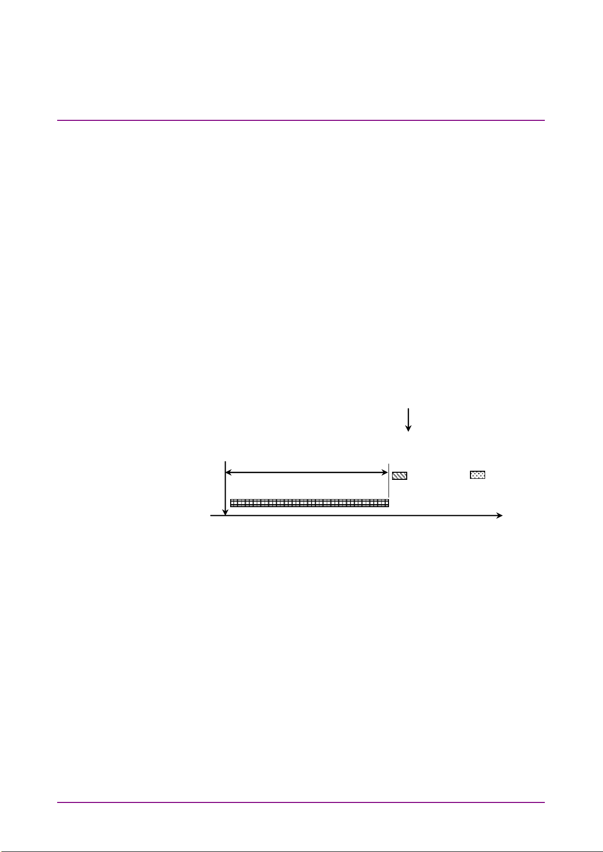
The following program message executes the single measurement,
detects the peak level and its wavelength, and read its wavelength.
SSI ; PKS PEAK ; TMK?
Figure 2.7-1 shows the message execution sequence when this message is
sent to the MS9740A. After executing
search is executed during sweeping,
read peak level and wavelength during sweeping are sometimes different
from those after sweeping.
SSI
, sweeping starts. As the peak
PKS PEAK
is executed as well. The
Figure 2.7-1 Message Processing Order
The control for processing the next command after completing processing
of the message sent first is called sync control.
Page 38
Chapter 2 Before Use
2-20
Time
Message received
SSI;Sweeping
PKS PEAK;
Peak search
detection
TMK?;
Save to marker
data output
Peak detected at this time point
Next message stopped
by*WAI
SSI
Executes single measurement
*CLS
Sets OPC bit to 0
*OPC?
Queries OPC bit
> 1
SSI execution completed when 1 received
PKS PEAK
Executes peak search
*OPC?
Queries OPC bit
> 1
PKS PEAK execution completed when 1 received
TMK?
Queries trace marker data
Sync control is performed by the following methods.
Using
•
Using
•
Using
•
By querying execution end
•
Using
•
The
be used for all messages.
Using
The
of the message sent before the
executing the next command.
*WAI
command
*OPC?
query
*OPC
command and
ESR2?
query
*WAI
command,
*WAI
*WAI
common command instructs processing to wait until processing
*OPC?
*ESR?
query
query, *OPC command, and
*WAI
command is completed before
*ESR?
query can
Example:
*OPC
Using
*OPC?
The
message processing.
Examples of Use:
SSI ; *WAI ; PKS PEAK ; TMK?
Figure 2.7-2 Sync Control by*WAI
common command queries the OPC bit indicating the end of
Page 39

2.7 Controlling Message Sync
2-21
Before Use
*OPC
Displays OPC bit in Standard Event Status
register
*ESR?
Standard Event Status register query
> 0
Returns 0, which means that a command is
running.
*ESR?
Standard Event Status register query
> 1
Returns 1, which means that no command is
running.
ALIN
Command of auto alignment execution
ALIN?
Queries result of auto alignment
> 1
Executing adjustment when 1 read
ALIN?
Queries result of auto alignment
> 0
Auto alignment completed when 0 read
SSI
Single measurement
*OPC
Using
*OPC
The
to 1 and displays the OPC bit when completing all command operation.
Examples of Use:
Querying Measurement End
The instrument program messages query the end of processing execution.
These queries send the following messages after confirming the
processing end.
Example of Use:
*ESR?
and
common command sets the standard event status register bit
2
Page 40

Chapter 2 Before Use
2-22.
*CLS
Sets OPC bit to 0
SSI
Performs single measurement
ESR2?
Queries end event register
> 0
Executing command when 0 read
ESR2?
Queries end event register
> 2
Not executing command and SSI execution
completed when 1 read
ANA
SMSR,2NDPEAK
Executes spectrum analysis by SMSR.
ESR2?
Queries end event register
> 0
Executing command when 0 read
ESR2?
Queries end event register
> 1
Spectrum analysis by SMSR completed when
1 read.
PKS PEAK
Executes peak search
ESR2?
Queries end event register
> 0
Executing command when 0 read
ESR2?
Queries end event register
> 1
Peak search completed when 1 read
TMK?
Queries trace marker data
ESR2?
Using
The commands in Table 2.6.3-1 set bit of the end event register when
execution is completed.
The following messages are sent after confirming the completion of
execution when reading the end event register using the
Example of Use:
ESE2?
qu e ry.
Page 41

3-1
Sample Program
Chapter 3 Sample Program
This chapter explains examples of sample programs and how to execute
them.
3.1
Executing Sample Programs ........................................ 3-2
3.1.1 Setting Sample Program Operating
Environment ..................................................... 3-2
3.1.2 Executing Sample Program .............................. 3-4
3.2 Example 1: Adjusting Optical System ........................... 3-6
3.3 Example 2: Measuring Center Wavelength and
Spectrum Width ............................................................ 3-8
3.4 Example 3: Reading Trace Data................................. 3-10
3
Page 42
Chapter 3 Sample Program
3-2
3.1 Executing Sample Programs
3.1.1 Setting Sample Program Operating Environment
The sample program operating environment is as follows.
PC
OS: Windows XP Professional Service Pack 2
VISA: NI-VISA Version 4.6
Program tool: Microsoft Visual C# 2008 Express Edition
MS9740A Optical Spectrum Analyzer
GPIB Address: 1
IP Address: 198.168.0.10
Subnet Mask: 255.255.255.0
Terminator Settings: CR/LF
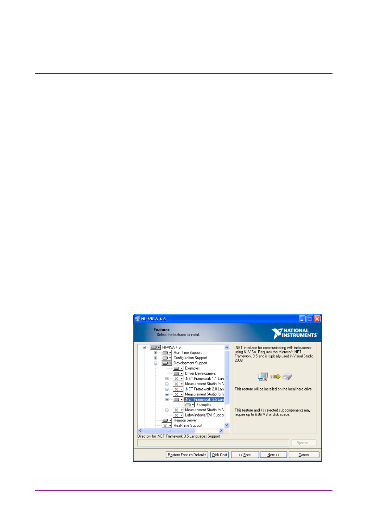
Installing NI-VISA
To use VISA at Visual C# 2008, add the following function at installation.
Development Support .NET Framework 3.5 Language Support
•
NI Measurement & Automation Explore ―.NET Framework 3.5
•
Language Support
Figure 3.1.1-1 Function Selection Screen at VISA Install
Page 43
3.1 Executing Sample Programs
3-3
Sample Program
Add Reference
.NET
OK
Setting Visual C# 2008
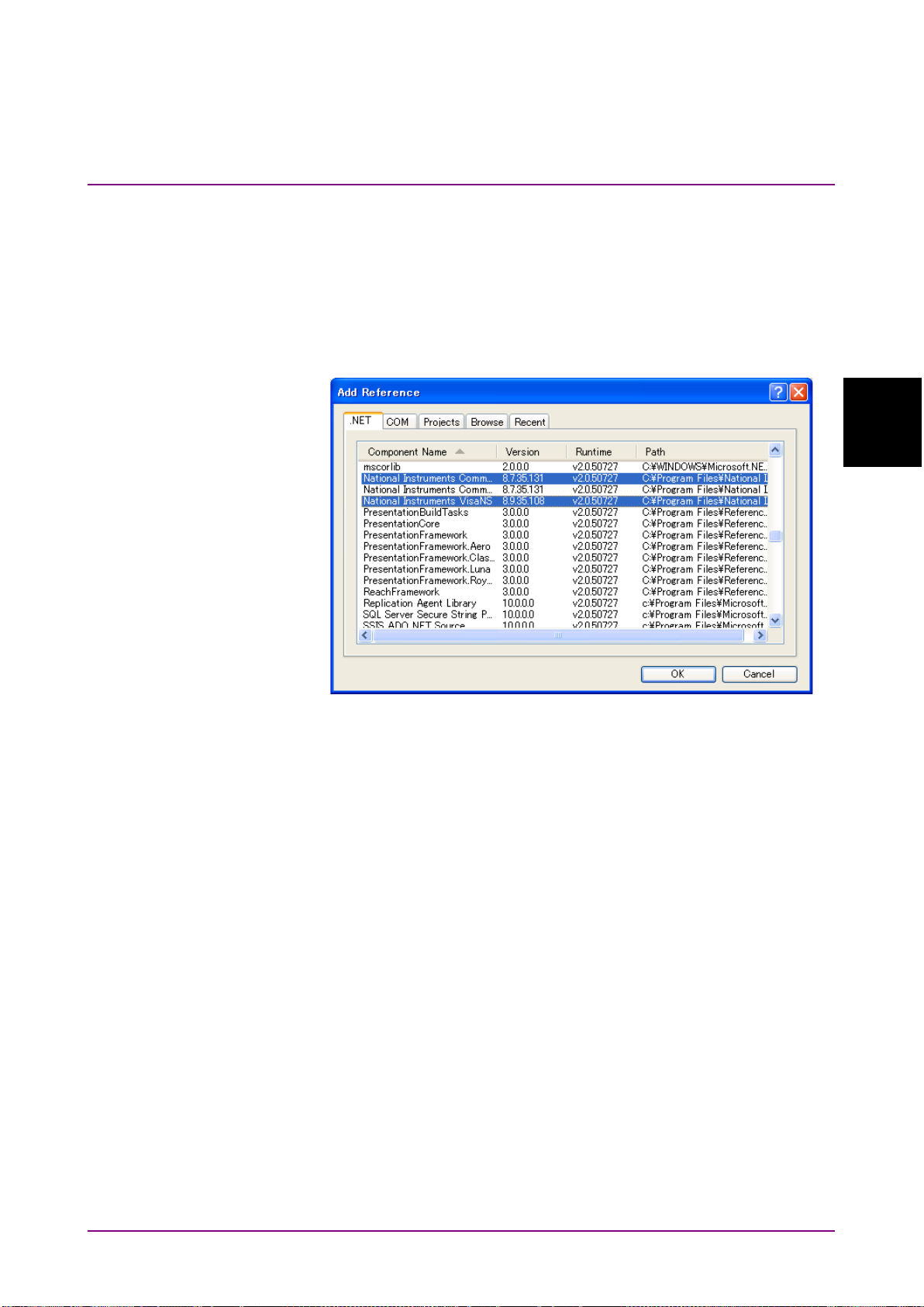
To use VISA at Visual C# 2008, operate as follows.
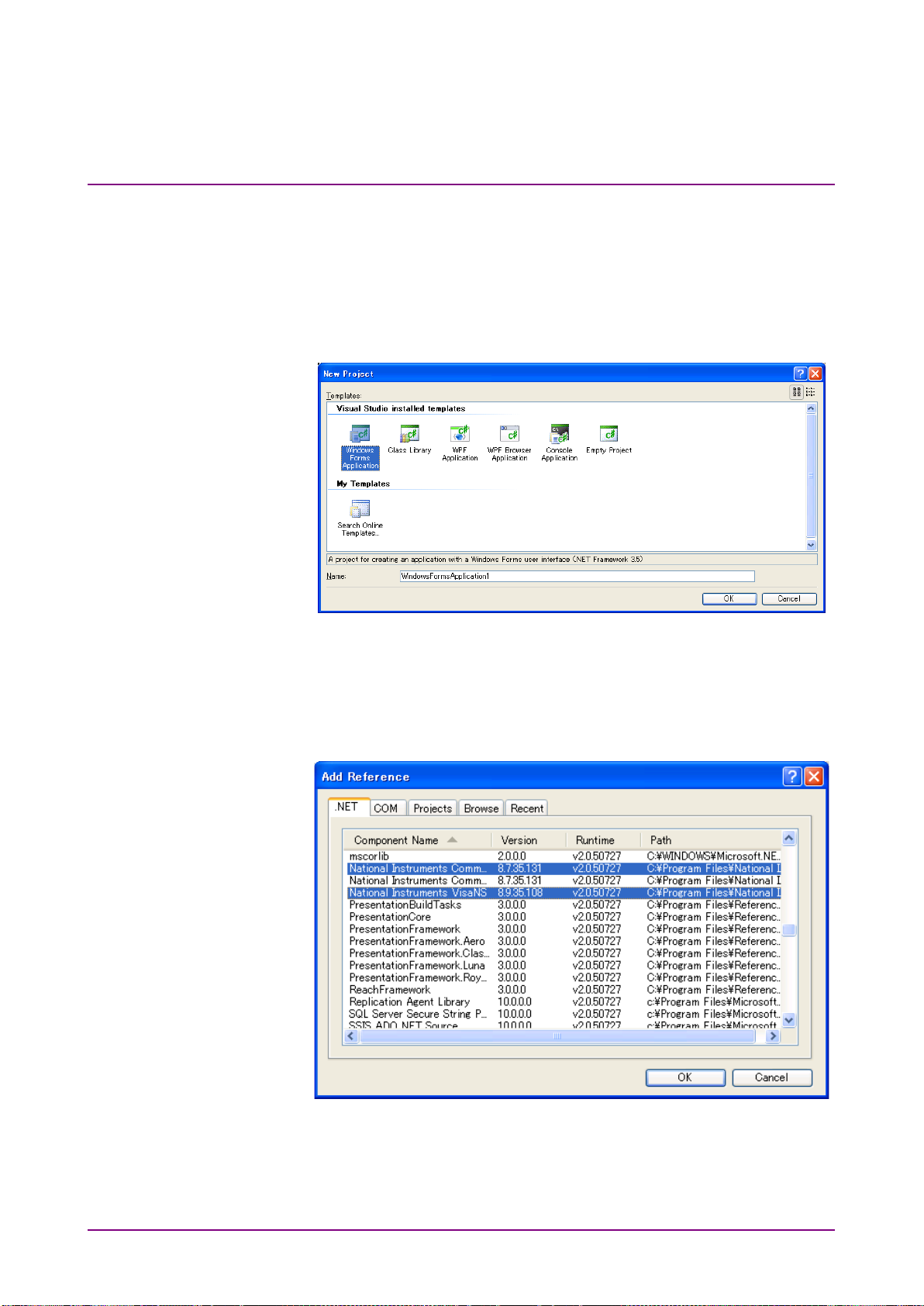
1. Click
2. Click the
3. Select National Instruments Common and National Instruments
tab in the Add Reference dialog box.
VisaNS, and click
Figure 3.1.1-2 Add Reference Dialog Box
at the Project menu.
.
3
Page 44
Chapter 3 Sample Program
3-4
New Project
Add Reference
.NET
OK
3.1.2 Executing Sample Program
The executing procedure for the sample program is as follows.
1. Start the Visual C# 2008.
2. Click
3. Select the Visual C# Windows Forms Application and click OK.
4. Start the screen editor and click
5. Click the
6. Select National Instruments Common and National Instruments
tab in the Add Reference dialog box.
VisaNS and click
from the File menu.
.
at the Project menu.
Page 45
3.1 Executing Sample Programs
3-5
Sample Program
Open Debug
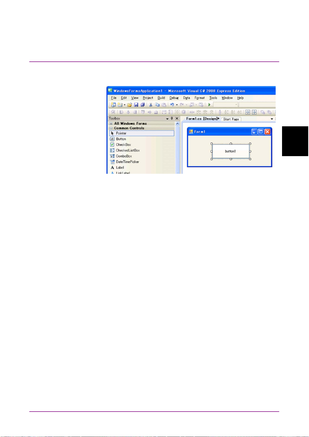
7. Referring to the sample program screen design figure arranges
control of the buttons in Form1.cs [Design].
3
8. Double-click the arranged button to open the screen for inputting
the source code.
9. Copy the sample program in this document and paste it into the
Form1.cs screen.
private void button1_Click(object sender, System.EventArgs e)
{
//Paste it into this part.
}
10. Change the IP address and GPIB address. The part Open
("TCPIP0::192.168.0.10::INSTR"); in the program must be changed
to match the operation environment.
For a LAN connection, the part "192.168.0.10" described above must
be changed to the IP address set at the MS9740A.
For a GPIB connection, the part "TCPIP0::192.168.0.10::INSTR"
described above must be changed to "GPIB::1::INSTR" (when
MS9740A GPIB address is 1).
11. Click
from the Debug menu.
Page 46

Chapter 3 Sample Program
3-6
3.2 Example 1: Adjusting Optical System
This sample program controls the instrument via the Ethernet interface.
Processing Flow
1. Start a session with the MS9740A with IP address setting
192.168.0.10.
2. Since optical axis adjustment takes time, set the receive timeout to
30 s.
3. The optical axis adjustment is executed by the
4. Wait for processing to terminate with
5. The optical axis adjustment is queried by the
6. The results are read on the console.
*OPC?
ALIN1
command.
command.
ALIN?
command.
Page 47

3.2 Example 1: Adjusting Optical System
3-7
Sample Program
// Open session
NationalInstruments.VisaNS.MessageBasedSession mbs =
(NationalInstruments.VisaNS.MessageBasedSession)
NationalInstruments.VisaNS.ResourceManager.GetLocalManager().
Open("TCPIP0::192.168.0.10::INSTR");
mbs.Timeout = 30000; // Timeout 30sec
// Write alignment command
mbs.Write("ALIN 1");
// Wait for alignment completion
mbs.Query("*OPC?");
// Get result
string ret = mbs.Query("ALIN?");
Console.WriteLine(ret);
3
Page 48

Chapter 3 Sample Program
3-8
3.3 Example 2: Measuring Center Wavelength and
Spectrum Width
This sample program controls the instrument via the GPIB interface.
Processing Flow
1. Start a session with the MS9740A with GPIB address setting 1.
2. Since single sweeping takes time, set the receive timeout to 30 s.
3. The analysis mode is set to the slice level 3 dB Envelope method by
ANA EVE
the
4. The single sweep is executed by the
5. Wait for processing to terminate with
6. The analysis result by Envelop method is queried by the
command.
, and 3 command.
SSI
command.
*OPC?
command.
ANA?
7. The results are read on the console.
Page 49

3.3 Example 2: Measuring Center Wavelength and Spectrum Width
3-9
Sample Program
// Opens session
NationalInstruments.VisaNS.MessageBasedSession mbs =
(NationalInstruments.VisaNS.MessageBasedSession)
NationalInstruments.VisaNS.ResourceManager.GetLocalManager().
Open("GPIB::1::INSTR");
mbs.Timeout = 30000; // Timeout 30sec
// Sets envelope analysis mode
mbs.Write("ANA ENV,3");
// Starts single sweep
mbs.Write("SSI");
// Waits for completion
mbs.Query("*OPC?");
// Acquires result
string ret = mbs.Query("ANAR?");
// Prints result
Console.WriteLine(ret);
3
Page 50

Chapter 3 Sample Program
3-10
3.4 Example 3: Reading Trace Data
This sample program controls the instrument via the Ethernet interface.
Processing Flow
1. Start a session with the MS9740A with IP address setting
192.168.0.10.
2. Since single sweeping takes time, set the receive timeout to 30 s.
3. Execute a single sweep using the
4. Wait until measurement is completed by the
5. Capture the waveform data of Trace Ausing the
6. Save the waveform data with the file name trace.txt to the D: drive.
SSI
command.
*OPC?
DMA?
command.
command.
Page 51

3.4 Example 3: Reading Trace Data
3-11
Sample Program
// Open session
NationalInstruments.VisaNS.MessageBasedSession mbs =
(NationalInstruments.VisaNS.MessageBasedSession)
NationalInstruments.VisaNS.ResourceManager.GetLocalManager().
Open("TCPIP0::192.168.0.10::INSTR");
mbs.Timeout = 30000; // Timeout 30sec
mbs.Write("SSI");
mbs.Query("*OPC?");
string ret = mbs.Query("DMA?");
// Write to file
System.IO.StreamWriter sr=new System.IO.StreamWriter(
(new System.IO.FileStream("d:\\trace.txt",
System.IO.FileMode.Create)),System.Text.Encoding.Default);
sr.WriteLine(ret);
sr.Close();
3
Page 52

Chapter 3 Sample Program
3-12.
Page 53

4-1
Message Details
Chapter 4 Message Details
This chapter describes the message details of remote control commands
for MS9740A.
4.1
Description of Message Explanations .......................... 4-2
4.2 Correspondence between Panel Operation and
Message ....................................................................... 4-3
4.2.1 Panel key .......................................................... 4-3
4.2.2 Function key ..................................................... 4-4
4.2.3 Messages with No Corresponding Panel
Operation ........................................................ 4-12
4.3 Message Function Category ....................................... 4-14
4.3.1 IEEE488.2 Common Messages and Native
Messages ....................................................... 4-14
4.3.2 System Management and Measurement
Commands ..................................................... 4-14
4.4 Device Message Details ............................................. 4-18
4.4.1 IEEE488.2 Common Message ....................... 4-18
4.4.2 Instrument dependent commands .................. 4-24
4
Page 54

Chapter 4 Message Details
4-2
<>
Parameters in angled bracket are input by the
programmer.
[]
Parameters in square brackets can be omitted.
|
Select one out of several choices.
{}
Group the choices.
A,B(C) or B(D)
<binary_data>
This string is in binary data format.
<user_drive>
Select one from E,F,G,H,I,J,K,L,M,N,O,P,
<file_name>
Character string within 32 characters enclosed
Example "Sample_LD(201)"
<numeric_value>
This is a string of numeric code.
Example 0,1.2E-6,2.35
<string>
This is a character string data
<switch>
This is a specific selection of message.
Example 100KHZ, LEFT
<trace>
Select one from A,B,C,D,E,F,G,H,I,J.
4.1 Description of Message Explanations
The following table shows the rules for describing messages.
Table 4.1-1 Rules for Describing Messages
Symbols Usage
In the case of A|B|C|D, select one from A, B,
C, or D.
In the case of A|B({C|D}), select one from
Q,R,S,T,U,V,W,X,Y,Z.
by double quotes (" ")
\,/,:,*,?,",<,>,|
cannot be used .
Page 55
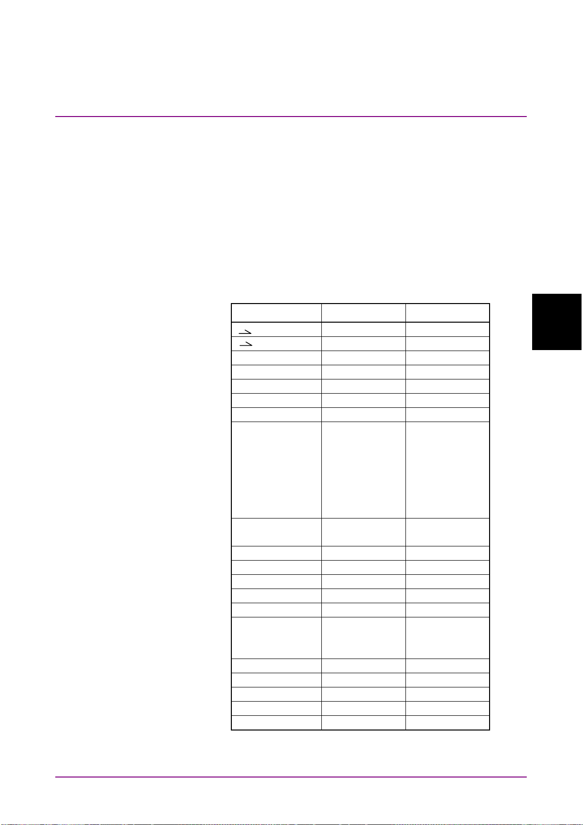
4.2 Correspondence between Panel Operation and Message
4-3
Message Details
Center
PKC —
Ref Lvl
PKL —
Auto Measure
AUT
AUT?
Center
CNT
CNT?
Copy
PRINT
—
Local
— —
Log(/div)
LOG
LOG?
MKA
EMK
MKA?
Peak Search
PKS
PKS?
TMK?
Preset
PRE —
Recall
RCXML
—
Ref
RLV
RLV?
Repeat
SRT —
Res
RES
RES?
Save*
SVCSV
SVXML
—
Single
SSI —
Span
SPN
SPN?
Stop
SST —
VBW
VBW
VBW?
Zone Marker
ZMK
ZMK?
4.2 Correspondence between Panel Operation and
Message
This section explains correspondence between panel operation and
message.
4.2.1 Panel key
Table 4.2.1-1 shows the corresponding keys to message.
“—” in the following table indicates that there is no corresponding
message.
Table 4.2.1-1 Correspondence between Panel Operation and Message
Key name Command Query
4
Marker Select
MKB
MKC
MKD
TMK
DMK
SVCSVA
MKB?
MKC?
MKD?
TMK?
DMK?
*: Refer to Table 4.2.2-2.
Page 56

Chapter 4 Message Details
4-4
Wavelength
Center
CNT
CNT?
Span
SPN
SPN?
Peak->Center
PKC —
Start
STA
STA?
Stop
STO
STO?
MkrValue Wl/Freq
MKV
MKV?
Value in Air/Vac
WDP
WDP?
Log (div)
LOG
LOG?
Ref Level
RLV
RLV?
Peak->RefLevel
PKL —
Linear Level
LLV
LLV?
Opt.Att On/Off
ATT
ATT?
Res/VBW/Avg
Res
RES
RES?
VBW
VBW
VBW?
Point Average
AVT
AVT?
Sweep Average
AVS
AVS?
Smooth
SMT
SMT?
Sampling Points
MPT
MPT?
Act-Res On/Off
ARES
ARES?
4.2.2 Function key
Table 4.2.2-1 and Table 4.2.2-2 show the correspondence between panel
key and messages.
There is no corresponding message, if — is indicated in the list item.
Table 4.2.2-1 Correspondence Between Function Key and Message
F1-F8 Key Name f1-f8 Key Name Command Query
Level Scale
Page 57
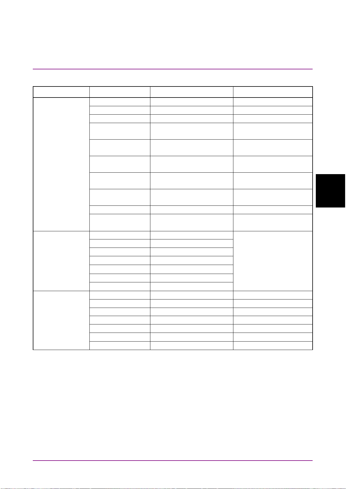
4.2 Correspondence between Panel Operation and Message
4-5
Message Details
Peak/Dip Search
Peak Search
PKS PEAK
PKS?
Dip Search
DPS DIP
DPS?
Off
EMK —
PKS NEXT
DPS NEXT
—
Last
PKS LAST
DPS LAST
—
PKS LEFT
DPS LEFT
—
Right
PKS RIGHT
DPS LIGHT
—
Auto/Manual
STHRS
STHRS
?
Search Threshold
STHR
STHR
?
PPC
PPC
?
Analysis
Threshold
ANA THR
ANA?
ndB Loss
ANA NDB
SMSR
ANA SMSR
Envelop
ANA ENV
RMS
ANA RMS
Spectrum Power
ANA PWR
Off
ANA OFF
Trace
Active Trace
TSL
TSL?
Trace type
TTP
TTP?
Storage Mode
SMD
SMD?
Calculation
FML
FML?
Display On/Off
TMD
TMD?
Graph
DSP
DSP?
Erase Overlap
EOV —
Table 4.2.2-1 Correspondence Between Function Key and Message (Cont’d)
F1-F8 Key Name f1-f8 Key Name Command Query
Next
Left
Search Threshold
Peak to Peak
CalculationOn/Off
4
ANAR?
Page 58

Chapter 4 Message Details
4-6
Application
DFB-LD Test
AP DFB
AP?
APR?
FP-LD Test
AP FP
LED Test
AP LED
PMD Test
AP PMD
WDM Test
AP WDM
LD Module Test
AP LD
Opt Amp Test
AP AMP
Opt Amp
AP AMP2
WDM Filter Test
AP WFIL
Slice Level
AP DFB
AP? DFB
Side Mode
Kσ
ndB Width
AP DFB,NDW
AP? DFB,NDW
Search Resolution
AP DFB,SRES
AP? DFB,SRES
Application
Display Mode
AP WDM,MPK
AP WDM,TBL
AP? WDM,MPK
AP? WDM,TBL
AP WDM,SIGNAL,WL
AP WDM,SIGNAL,LV
AP? WDM,SIGNAL,WL
AP? WDM,SIGNAL,LV
Noise Parameter
AP WDM,NOISE
AP WDM,NNRMZ
AP? WDM,NOISE
AP? WDM,NNRMZ
AP WDM,NOISE,POINT
AP? WDM,NOISE,POINT
Table 4.2.2-1 Correspondence Between Function Key and Message (Cont’d)
F1-F8 Key Name f1-f8 Key Name Command Query
(Multi Channel)
Test
Application
(DFB-LD)
(WDM)
Signal Parameter
Noise Position
AP WDM,SNR
AP WDM,REL
AP? WDM,SNR
AP? WDM,REL
Page 59
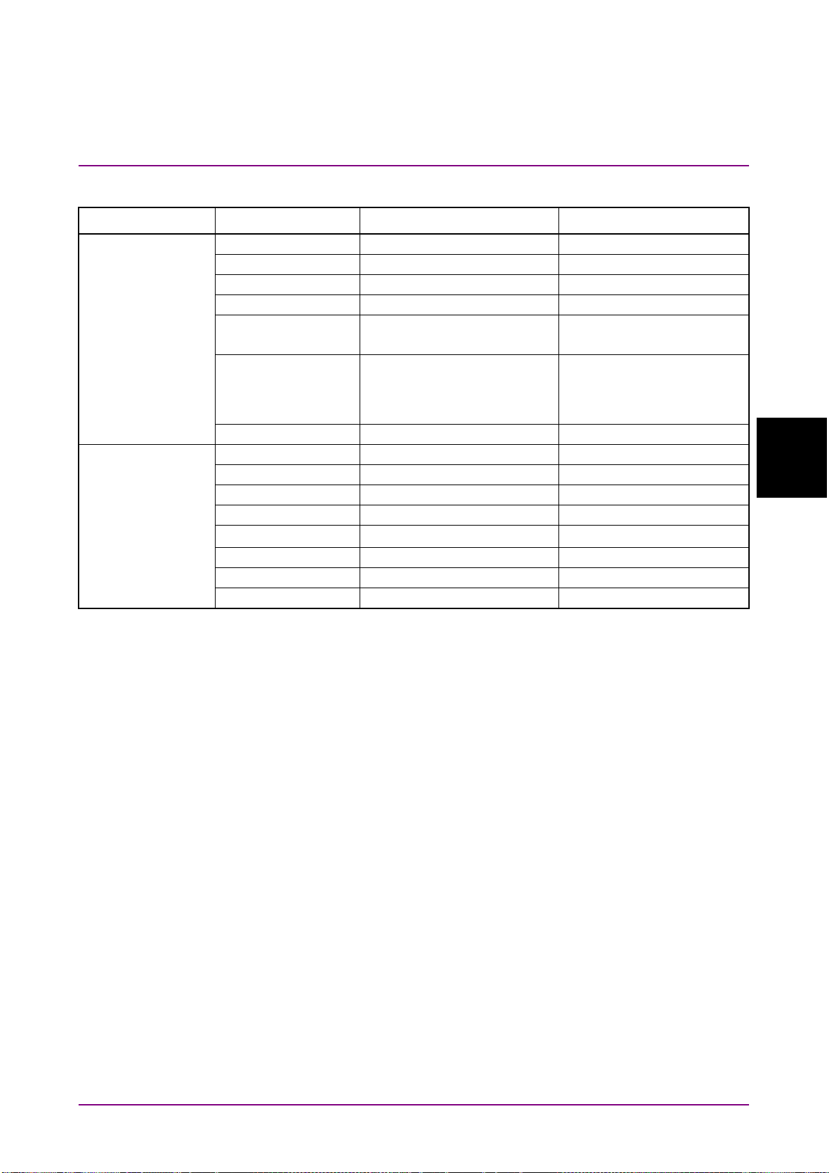
4.2 Correspondence between Panel Operation and Message
4-7
Message Details
Application
SMSR Parameter
AP LD,SMSR
AP? LD,SMSR
K
σ
AP LD,K
AP? LD,K
ndB Width
AP LD,NDW
AP? LD,NDW
Search Resolution
AP LD,SRES
AP? LD,SRES
Signal Parameter
AP LD,SIGNAL,WL
AP LD,SIGNAL,LV
AP? LD,SIGNAL,WL
AP? LD,SIGNAL,LV
AP LD,NOISE
AP? LD,NOISE
Noise Position
AP LD,NOISE,POINT
AP? LD,NOISE,POINT
Application
Method
AP AMP,PRM
AP? AMP,PRM
Parameter
AP AMP,PRM
AP? AMP,PRM
Write to
AP AMP,MSL
AP? AMP,MSL
Ext Trigger Delay
TDL
TDL?
Res Cal
AP AMP,CAL
AP? AMP,CAL
Pin
AP AMP,PIN
AP? AMP,PIN
Pout
AP AMP,POUT
AP? AMP,POUT
Pase
AP AMP,PASE
AP? AMP,PASE
Table 4.2.2-1 Correspondence Between Function Key and Message (Cont’d)
F1-F8 Key Name f1-f8 Key Name Command Query
(LD Module)
Noise Parameter
AP LD,NNRMZ
AP LD,THR
AP? DL,NNRMZ
AP? LD,THR
(Opt Amp Test)
4
Page 60

Chapter 4 Message Details
4-8
Application
ISS Method
AP AMP2,PRM
AP? AMP2,PRM
AP AMP2,PRM
AP AMP2,STHR
AP? AMP2,PRM
AP? AMP2,STHR
Opt Amp Test
AP AMP2,ASE
AP? AMP2,ASE
AP? AMP2,OBPF
Write to
AP AMP2,MSL
AP? AMP2,MSL
Pin
AP AMP2,PIN
AP? AMP2,PIN
Pout
AP AMP2,POUT
AP? AMP2,POUT
Application
Test Parameter
AP WFIL,BWCL
AP WFIL,TCL
AP? WFIL,BWCL
AP? WFIL,TCL
Dynamic Range
DRG
DRG?
Ext Trigger Delay
MDM
TDL*1
MDM?
TDL?
Interval Time
ITM
ITM?
Power Monitor
PWR*2
SPC*3
PWR?
PWRR?
MM Mode
MMM
MMM?
Table 4.2.2-1 Correspondence Between Function Key and Message (Cont’d)
F1-F8 Key Name f1-f8 Key Name Command Query
(Opt Amp (Multi
Channel) Test)
(WDM Filter Test)
Measure Mode
Channel Parameter
Parameter
AP AMP2,WL
AP AMP2,SLV
AP AMP2,ASE,POINT
AP AMP2,ASE,AREA,FUNC
AP AMP2,ASE,AREA
AP AMP2,OBPF
AP WFIL,CHDT
AP WFIL,LVL
AP WFIL,RPS
AP WFIL,SLV
AP WFIL,STHR
AP? AMP2,WL
AP? AMP2,SLV
AP? AMP2,ASE,POINT
AP?
AMP2,ASE,AREA,FUNC
AP? AMP2,ASE,AREA
AP? WFIL,CHDT
AP? WFIL,LVL
AP? WFIL,RPS
AP? WFIL,SLV
AP? WFIL,STHR
*1: TDL sets the Trigger Delay.
*2: Command for starting power monitoring
*3: Command for stopping power monitoring
Page 61

4.2 Correspondence between Panel Operation and Message
4-9
Message Details
Cal
Wl Offset
WOFS
WOFS?
Level Offset
LOFS
LOFS?
Wl Cal(Ext)
WCAL 1
WCAL?
Wl Cal(Ref)
WCAL 2
WCAL?
Wl Cal(Init)
WCAL 0
WCAL?
Auto Align
ALIN
—
Res Cal
RCAL
—
Auto Cal On/Off
ZCAL*4
ZCAL?*5
Auto Offset On/Off
AOFS
AOFS?
Zero Cal
ZCAL
ZCAL?
λMkr_A
MKA
MKA?
λMkr_B
MKB
MKB?
LMkr_C
MKC
MKC?
LMkr_D
MKD
MKD?
TMkr
TMK
TMK?
ΔMkr
DMK
DMK?
Erase
EMK —
Zone Marker
Zone Center
ZMK WL
ZMK WL
ZMK WL
ZMK WL
Zone->Span
ZMK SPN
—
Zoom Out/In
ZMK ZOOM
ZMK ZOOM
ZMK ERS
—
Others
Optical Output
On/Off
OPT
OPT?
Title
TTL
TER
TTL?
Table 4.2.2-1 Correspondence Between Function Key and Message (Cont’d)
F1-F8 Key Name f1-f8 Key Name
Marker
Zone Width
Command
Query
4
Erase
*4: Auto Cal On/Off cannot be set by the remote control.
For details, refer to ZCAL in 4.4.2 “Instrument dependent
commands”.
*5: Auto Cal On/Off settings cannot be queried by the remote control.
For details, refer to ZCAL in 4.4.2 “Instrument dependent
commands”.
Page 62

Chapter 4 Message Details
4-10
Config*6
Interface Settings
DELM
TRM
DELM?
TRM?
COLOR
PMOD
COLOR?
PMOD?
System Settings
BUZ
BUZ?
System Info
SYSINFO?
Option Info
*OPT?
Copying file
PRTXML
Querying file list
Software Install
—
Table 4.2.2-1 Correspondence Between Function Key and Message (Cont’d)
F1-F8 Key Name f1-f8 Key Name Command Query
Copy Settings
—
—
File Operation
•
copy
CPCOPYDAT
CPCSV
CPSYSINFO
CPXML
Deleting file
•
DELCOPYDAT
DELCSV
DELSYSINFO
DELXML
Moving file
•
MVCOPYDAT
MVCSV
MVSYSINFO
MVXML
File protect
•
PRTCOPYDAT
PRTCSV
PRTSYSINFO
•
LISTCOPYDAT?
LISTCSV?
LISTSYSINFO?
LISTXML?
Querying file protect
•
PRTCOPYDAT?
PRTCSV?
PRTSYSINFO?
PRTXML?
*6: Before using the Config screen message, send
Refer to 4.3.2 “System Management and Measurement Commands”.
SYS CONFIG,ACT
.
Page 63
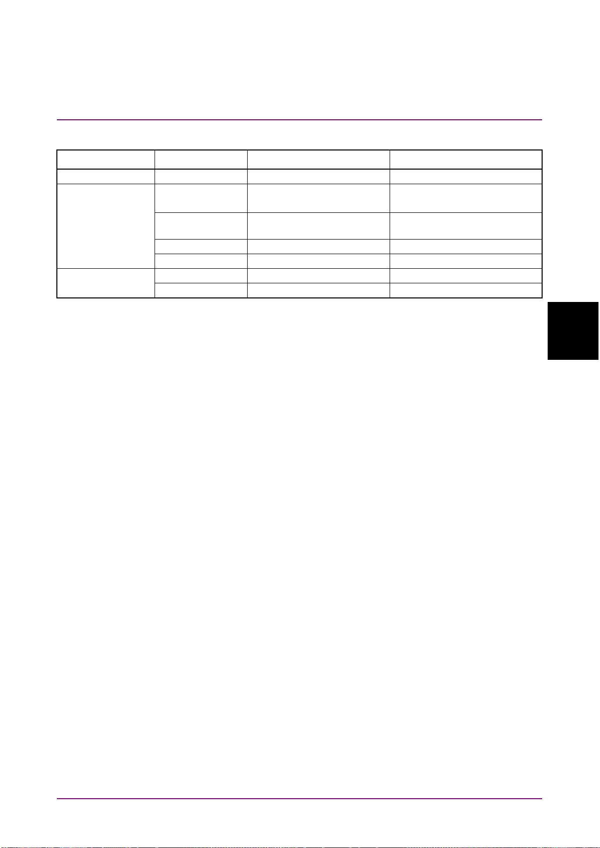
4.2 Correspondence between Panel Operation and Message
4-11
Message Details
Preset
Preset
PRE —
SVCSV
SVXML
—
Save CSV
SVCSVA
—
Save CSV
SVCSV
—
Save XML
SVXML
—
Device
RCXML
—
Recall XML
RCXML
—
Table 4.2.2-2 Correspondence Between Function Key and Message
Panel key f1-f8 Key Name Command Query
Save Device
All Data
Recall
4
Page 64

Chapter 4 Message Details
4-12
*CLS
Clears event register
*ESE
Sets/queries standard event enable register
*ESR
Queries standard event register
*IDN
Queries device information
*OPC
Sets/queries bit display indicating message processing
completion
*RST
Initializes MS9740A setting conditions
*SRE
Sets/queries service request enable register
*STB
Queries status byte register
*TST
Queries results of self-diagnosis
*WAI
Waits previous sent message completion
DBA
Queries trace A data (binary format)
DBB
Queries trace B data (binary format)
DBC
Queries trace C data (binary format)
DBD
Queries trace D data (binary format)
DBE
Queries trace E data (binary format)
DBF
Queries trace F data (binary format)
DBG
Queries trace G data (binary format)
DBH
Queries trace H data (binary format)
DBI
Queries trace I data (binary format)
DBJ
Queries trace J data (binary format)
DCA
Queries trace A wavelength and measurement point
DCB
Queries trace B wavelength and measurement point
DCC
Queries trace C wavelength and measurement point
DCD
Queries trace D wavelength and measurement point
DCE
Queries trace E wavelength and measurement point
DCF
Queries trace F wavelength and measurement point
DCG
Queries trace G wavelength and measurement point
DCH
Queries trace H wavelength and measurement point
DCI
Queries trace I wavelength and measurement point
DCJ
Queries trace J wavelength and measurement point
4.2.3 Messages with No Corresponding Panel Operation
Command messages with no corresponding panel operation are listed
below.
Table 4.2.3-1 Messages with No Corresponding Panel Operation
Message Details
Page 65

4.2 Correspondence between Panel Operation and Message
4-13
Message Details
DMA
Queries trace A data (text format)
DMB
Queries trace B data (text format)
DMC
Queries trace C data (text format)
DMD
Queries trace D data (text format)
DME
Queries trace E data (text format)
DMF
Queries trace F data (text format)
DMG
Queries trace G data (text format)
DMH
Queries trace H data (text format)
DMI
Queries trace I data (text format)
DMJ
Queries trace J data (text format)
DQA
Queries trace A data (comma-delimited text format)
DQB
Queries trace B data (comma-delimited text format)
DQC
Queries trace C data (comma-delimited text format)
DQD
Queries trace D data (comma-delimited text format)
DQE
Queries trace E data (comma-delimited text format)
DQF
Queries trace F data (comma-delimited text format)
DQG
Queries trace G data (comma-delimited text format)
DQH
Queries trace H data (comma-delimited text format)
DQI
Queries trace I data (comma-delimited text format)
DQJ
Queries trace J data (comma-delimited text format)
ERR
Queries error code
ESE2
Sets/queries end event enable register
ESE3
Sets/queries error event enable register
ESR2
Queries end event register
ESR3
Queries error event register
GHC
Queries screen data
LVS
Queries whether the level scale is log or linear
MOD
Queries measurement mode
PPMK
Obtains Peak to Peak level of trace.
SOFTVER
Queries the software version.
SYS
Switches/queries measurement commands and system
commands
WSS
Simultaneously sets/queries start and stop wavelength.
Table 4.2.3-1 Messages with No Corresponding Panel Operation (Cont’d)
Message Details
4
Page 66
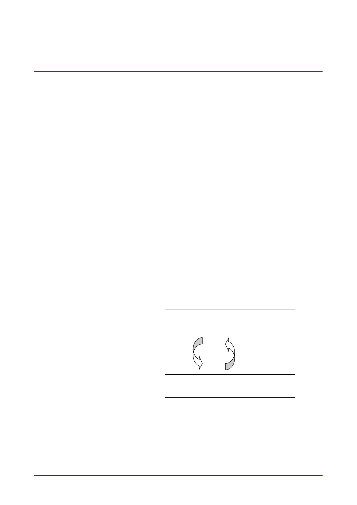
Chapter 4 Message Details
4-14
System management
mode (CONFIG)
Measurement mode
(OSA)
SYS CONFIG,ACT
(Move to system management
mode)
SYS OSA,ACT
(Move to measurement
mode)
Executable s
ystem
management command
Executable measurement
command
4.3 Message Function Category
4.3.1 IEEE488.2 Common Messages and Native Messages
The device messages are classified by the IEEE488.2 common commands
and instrument dependent commands.
IEEE488.2 Common Commands and Queries
The device messages are specified by IEEE488.2-1992. The header first
letter of these messages is an asterisk symbol (*).
Common messages and queries are defined as required or optional by
IEEE standard.
The common messages used with this instrument are only the messages
defined as obligatory by the standard.
Native Messages
These are the device messages required for the panel operations and
measurement functions of this instrument.
4.3.2 System Management and Measurement Commands
The device messages used by this model are divided into system
management commands, measurement commands, and neutral
commands that can be used anytime.
This machine has a system management mode and a measurement mode.
The mode must be switched (
to use.
Figure 4.3.2-1 Switching System Status
SYS
command) for to the type of command
Page 67

4.3 Message Function Category
4-15
Message Details
System Management Command
System management commands are the device messages corresponding
to the operations set at the
the following operations. These commands are listed in Table 4.3.2-2.
Listing, saving, copying, deleting, moving and protecting of files
•
Reading software version and option information
•
Setting communications interface and buzzer
•
To use system management commands, send
Measurement commands cannot be used during this time.
Measurement Commands
Measurement commands are the device messages for the measurement
functions of the optical spectrum analyzer.
To use measurement commands, send
management commands cannot be used during this time. These
commands are listed in Table 4.3.2-3.
F6 Config
screen.
SYS OSA,ACT.
There are commands for
SYS CONFIG,ACT.
System
4
Neutral Commands
Neutral commands for switching between system management
commands for saving IEEE488.2 common device messages, saving screen
image files and initializing parameters, and measurement commands do
not belong to either system management commands or measurement
commands. These commands can be used at any time. These commands
are listed in Table 4.3.2-1.
The following commands can be used at any time.
Page 68

Chapter 4 Message Details
4-16
*CLS
*STB
*ESE
*TST
*ESR
*WAI
*IDN
PRE
*OPC
PMOD
*OPT
PRINT
*RST
SYS
*SRE
BUZ
LISTSYSINFO
COLOR
LISTXML
CPCOPYDAT
MVCOPYDAT
CPCSV
MVCSV
CPSYSINFO
MVSYSINFO
CPXML
MVXML
DELCOPYDAT
PRTCOPYDAT
DELCSV
PRTCSV
DELM
PRTSYSINFO
DELSYSINFO
PRTXML
DELXML
SOFTVER
LISTCOPYDAT
SYSINFO
LISTCSV
TRM
Table 4.3.2-1 Neutral Commands
The following system management commands can be used after sending
SYS CONFIG,ACT
.
Table 4.3.2-2 System Management Command
Page 69

4.3 Message Function Category
4-17
Message Details
ALIN
DCJ
ESR2
SMD
AOFS
DMA
ESR3
SMT ANA DMB
GHC SPC
ANAR
DMC
FML SPN
AP DMD
ITM SRT APR DME
LLV SSI
ARES
DMF
LOFS
SST
ATT DMG
LOG STA AUT DMH
LVS STHR
AVS DMI
MDM
STHRS
AVT DMJ
MKA
STO
CNT
DMK
MKB
SVCSVA
DBA
DPS
MKC
SVCSV
DBB
DSP
MKD
SVXML
DBC
DQA
MKV
TDL
DBD
DQB
MPT
TER
DBE
DQC
MMM
TMD DBF
DQD
MOD
TMK
DBG
DQE
OPT
TSL
DBH
DQF
PKC
TTL DBI
DQG
PKL
TTP
DBJ
DQH
PKS
VBW
DCA
DQI
PPC
WCAL
DCB
DQJ
PPMK
WDP
DCC
DRG
PWR
WOFS
DCD
DSP
PWRR
WSS
DCE
EMK
RCAL
ZCAL
DCF
EOV
RCXML
ZMK
DCG
ERR
RES
DCH
ESE2
RLV
DCI
ESE3
SRT
The following measurement commands can be used after sending
OSA,ACT
.
Table 4.3.2-3 Measurement Commands
SYS
4
Page 70

Chapter 4 Message Details
4-18
4.4 Device Message Details
4.4.1 IEEE488.2 Common Message
This subsection describes the IEEE 488.2 common messages supported
by MS9740A.
*CLS [Clear Status]
Function
1. The
2. The
*CLS
common command clears the following registers.
● Standard event status register
● Extended event status register
● Error event register
Therefore, bits 5, 3, and 2 of status byte register become 0.
The setting value of each enable register does not vary depending on
*CLS
.
*CLS
common command clears the status byte register when
sent before the query after the program message terminator.
All unread messages in the output queue are cleared at this time.
The relevant message example indicates below.
CNT 1305.8
SPN 1000
*CLS ; CNT?
Syntax
*CLS
Page 71

4.4 Device Message Details
4-19
Message Details
*ESE [Event Status Enable]
bit7 : 27 = 128
Power-on
bit6 : 26 = 64
Not used
bit5 : 25 = 32
Command error
bit4 : 24 = 16
Execution error
bit3 : 23 = 8
Unique device error
bit2 : 22 = 4
Query error
bit1 : 21 = 2
Not used
bit0 : 20 = 1
Completion of operation
Function
This command sets the standard event status enable register.
The setting of 0 to 255 is equivalent to 8-bit binary.
The standard event status mask bit is set to 0.
The command queries the standard event status enable register value.
Syntax
*ESE <numeric_value>
*ESE?
<numeric_value> = bit0 + bit1 + bit2 + bit3 + bit4 + bit5 + bit6 + bit7
4
Range 0 to 255
Example of Use
The following example shows how to mask bits 7 to 4 and permit bits 3 to
0. The command data is specified in decimal.
*ESE 15
*ESE?
>15
Page 72

Chapter 4 Message Details
4-20
*ESR [Standard Event Status Register]
*IDN [Identification]
Function
This command queries the standard event status register value.
The standard event status register value is cleared after readout.
This value is the logical product of the 8 bits set by
Syntax
*ESR?
Example of Use
The following example queries the value of the standard event status
register. The data is the value when an execution error or command error
occurs. There are a total of 48 values (bit 5 = 2
as shown in Table 2.6.3-1.
*ESR?
>48
Function
This command queries product supplier name, model name, serial
number, and firmware.
Syntax
*IDN?
Example of Use
*IDN?
>Anritsu,MS9740A,6200123456,1.00.00
*ESE.
5
= 32 and bit 4 = 24 = 16)
Page 73

4.4 Device Message Details
4-21
Message Details
*OPC [Operation Complete]
Option number
Option name
1
GPIB interface
2
Light Source for Wavelength Calibration
3 to 64
Not used
Function
*OPC
If a
to 1 once all active processes are completed.
If a
complete.
command is received, the operation completion bit (bit 0) is set
*OPC?
query is received, 1 is returned once all active processes are
The wait for operation completion set by
following events:
● Power ON
● Reception of DCL or SCL on the IEEE488.1 interface
● Reception of the
● Reception of the
● Completion of all active processing
Syntax
*OPC
*OPC?
Example of Use
*OPC?
>1
*OPT [Option Identification Query]
Function
This command queries what options are installed.
The response is a numeric from 1 to 64 corresponding to options 1 to 64.
The returned value is 0 when no options are installed.
*CLS
*RST
command
command
*OPC/*OPC?
is disabled after the
4
Syntax
*OPT?
Example of Use
*OPT?
>1,1,0,0,0,0,0,0,0,0,0,0,0,0,0,0,0,0,0,0,0,0,0,0,0,0,0,0
,0,0,0,0,0,0,0,0,0,0,0,0,0,0,0,0,0,0,0,0,0,0,0,0,0,0,0,0
,0,0,0,0,0,0,0,0
Page 74

Chapter 4 Message Details
4-22
bit7 : 27 = 128
Not used
bit6 : 26 = 64
Always 0
bit5 : 25 = 32
Standard event status
register
bit4 : 24 = 16
MAV
bit3 : 23 = 8
Error event register
bit2 : 22 = 4
End event register
bit1 : 21 = 2
Not used
bit0 : 20 = 1
Not used
*RST [Reset]
*SRE [Service Request Enable]
Function
This command initializes the setting conditions. However, the following
items are not initialized.
● GPIB address
● Output queue
● Service request enable register
● Standard event status enable register
Syntax
*RST
Function
This command sets the service request enable register.
The setting of 0 to 255 is equivalent to 8-bit binary.
The status byte register mask bit is set to 0.
This command queries the service request enable register value.
Syntax
*SRE <numeric_value>
*SRE?
<numeric_value> = bit0 + bit1 + bit2 + bit3 + bit4 + bit5
+ bit6 + bit7
Range 0 to 255
Example of Use
The following example shows how to mask bits 7, 6, 1, and 0 and permit
bits 5 and 2.
*SRE 60
*SRE?
>60
Page 75

4.4 Device Message Details
4-23
Message Details
*STB [Status Byte]
Function
This command queries the status byte register.
Syntax
*STB?
*TST [Self-Test Query]
Function
This command queries
0 Error does not occur after completing test
1 Te st cannot be executed. Even though test can be executed, error
Syntax
*TST?
Example of Use
*TST?
>0
*WAI [Wait to Continue]
Function
This command holds execution of the next message until processing of
the message sent before
Syntax
*WAI
Example of Use
SSI;*WAI;DBA?
occurs.
the results of self-diagnosis.
*WAI
is completed.
4
Page 76

Chapter 4 Message Details
4-24
4.4.2 Instrument dependent commands
ALIN [Auto Alignment]
Function
This command
4 of the end event status register (execution complete bit) is set to 1. If a
command other than
command displays an execution error.
Syntax
ALIN 0|1|2
ALIN?
0: Restore the data to default value.
1: Execute optical alignment and save the data.
2: Forced shutdown
executes optical alignment. When alignment is complete, bit
ALIN 2
is received during optical alignment, this
Response Data
0|1|2|3
0: Normal end
1: During alignment
2: Aborted optical alignment due to lack of optical level
3: Aborted optical alignment due to other abnormality
Example of Use
ALIN 1
ALIN?
>0
Page 77

4.4 Device Message Details
4-25
Message Details
ANA [Spectrum Analysis]
<switch>
Analysis method
Number of <parameter>
ENV
Envelope method
1
NDB
ndB-Loss method
1
PWR
Spectrum analysis for
integral power
0
RMS
RMS method
2
SMSR
SMSR method
1
THR
Threshold method
1
OFF
Closes spectrum analysis
display
0
Function
This command sets the spectrum analysis method and parameters, and
then executes analysis.
When the processing is finished, bit 0 (measurement end bit) of the end
event status register is set to 1.
The query command reads the method of spectrum analysis function and
parameter.
The parameter details using each analysis method are explained
individually as follows.
Syntax
ANA <switch>[,<parameter>,<parameter>,,…]ANA?
Response Data
<switch>,<parameter>,,
<switch>=ENV|NDB|OFF|PWR|RMS|SMSR|THR
<parameter>
status of <switch>.
4
: The number of <parameter> varies depending on the
<parameter> can be omitted. If <parameter> is omitted, this command
executes analysis with the current set parameter.
Page 78

Chapter 4 Message Details
4-26
ANA ENV [Spectrum Analysis (Envelope)]
Function
This command sets the envelop method and cut level and executes the
spectrum analysis.
This command reads the spectrum analysis method and cut level value.
Syntax
ANA ENV,<numeric_value>
ANA?
Response Data
ENV,<numeric_value>
<numeric_value>:
Example of Use
To set the cut level to 10 dB using the envelop method:
ANA ENV,10
ANA?
>ENV,10.0
Cut level (dB) 0.1 to 20.0
ANA NDB [Spectrum Analysis (NDB)]
Function
This command sets the ndB-Loss method and loss and performs
spectrum analysis.
This command queries the loss.
Syntax
ANA NDB,<numeric_value>
ANA?
Response Data
NDB,<numeric_value>
<numeric_value>:
Example of Use
To set the loss to 20 dB using the ndB Loss method:
ANA NDB,20
ANA?
>NDB,20.0
Loss (dB) 0.1 to 50.0,
Page 79

4.4 Device Message Details
4-27
Message Details
ANA OFF [Spectrum Analysis OFF]
Function
This command closes the spectrum analysis display.
Syntax
ANA OFF
ANA?
Response Data
OFF
Example of Use
ANA OFF
ANA?
>OFF
ANA PWR [Spectrum Analysis (Spectrum Power)]
Function
This command executes the spectrum analysis of the integral power.
This command reads the spectrum analysis method.
Syntax
ANA PWR
ANA?
Response Data
PWR
Example of Use
ANA PWR
ANA?
>PWR
4
Page 80

Chapter 4 Message Details
4-28
No.
Parameter type
Range
Details
1
<numeric_value>
0.1 to 50.0
Spectrum level (dB)
2
<numeric_value>
1.00 to 10.00
K: Standard deviation factor
ANA RMS [Spectrum Analysis (RMS)]
Function
This command sets the RMS method, slice level, and factor K and
executes the spectrum analysis method.
This command queries the spectrum analysis method, slice level and
factor K.
Syntax
ANA RMS,<numeric_value>,<numeric_value>
ANA?
Response Data
RMS,<numeric_value>,<numeric_value>
Example of Use
To set the cut level to 20 dB and the factor to 2.35 using the RMS
method:
ANA RMS,20,2.35
ANA?
>RMS,20.0,2.35
Page 81

4.4 Device Message Details
4-29
Message Details
ANA SMSR [Spectrum Analysis (SMSR)]
Function
This command sets the SMSR method and detecting method and
performs the spectrum analysis.
This command queries the spectrum analysis method and detecting
method.
Syntax
ANA SMSR,<switch>
ANA?
Response Data
SMSR,<switch>
<switch>:
Example of Use
To analyze the left side of the SMSR method:
ANA SMSR,LEFT
ANA?
>SMSR,LEFT
Detecting method
4
{ 2NDPEAK|LEFT|RIGHT }
ANA THR [Spectrum Analysis (THR)]
Function
This command sets the Threshold method and cut level and performs the
spectrum analysis.
This command queries the spectrum analysis method and cut level.
Syntax
ANA THR,<numeric_value>
ANA?
Response Data
THR,<numeric_value>
<numeric_value>:
Example of Use
To set the cut level to 30 dB using the Threshold method:
ANA THR,30
ANA?
>THR,30.0
Cut level (dB) 0.1 to 50.0
Page 82

Chapter 4 Message Details
4-30
Envelope method
Center wavelength
(nm|THz)
Spectrum width
(nm|THz)
None
ndB Loss method
Center wavelength
(nm|THz)
Spectrum width
(nm|THz)
Longitudinal
mode count
Integral power
Power (dBm)
Center
(nm|THz)
None
RMS method
Center wavelength
(nm|THz)
Spectrum width
(nm|THz)
Standard
deviation σ
SMSR method
Wavelength
(nm|THz)
Level difference
None
Threshold method
Center wavelength
(nm|THz)
Spectrum width
(nm)
None
ANAR [Spectrum Analysis Result]
Analysis method Numeric value 1 Numeric value 2 Numeric value 3
Function
This command queries the spectrum analysis result.
Syntax
ANAR?
Response Data
<numeric_value>,<numeric_value>[,<numeric_value>]
The details of spectrum analysis method and numeric values
are as follows.
Table 4.4.2-1 Response of ANAR?
wavelength
difference
The center wavelength, spectrum width and wavelength difference are –1
when analysis cannot be performed. The level difference when analysis
cannot be performed is –999.99.
(dB)
Page 83

4.4 Device Message Details
4-31
Message Details
Example of Use
Queries analysis results at envelope method
ANAR?
>1565.223,1.08
Queries analysis results at ndB Loss method
ANAR?
>1550.100,12.840,9
Queries analysis results at integral power
ANAR?
>-15.44,1550.100
Queries analysis results at RMS method
ANAR?
>1309.330,5.390,2.350
Queries SMSR analysis
ANAR?
>0.920,38.74
Queries SMSR analysis results (when cannot perform analysis)
ANAR?
>-1,-999.99
Queries analysis results at Threshold method
ANAR?
>1298.430,23.52
4
AOFS [Auto Offset]
Function
This command enables/disables the Auto Offset adjustment.
This command queries the On/Off status of the Auto Offset adjustment.
Syntax
AOFS OFF|ON
AOFS?
ON: Enables the Auto Offset adjustment.
OFF: Disables the Auto Offset adjustment.
Response Data
OFF|ON
Example of Use
AOFS OFF
AOFS?
>OFF
Page 84

Chapter 4 Message Details
4-32
<switch>
Application Type
AMP
Optical amplifier
AMP2
Optical amplifier (WDM)
DFB
Distributed feedback laser diode
FP
Fabry-Perot laser diode
LD
Laser diode module
LED
Light-emitting diode
OFF
End of application function
PMD
Polarization mode dispersion
WDM
Wavelength division multiplex transmission
WFIL
WDM Filter
AP [Application]
Function
This command sets the type of application function and parameter and
executes the analysis.
When the processing is complete, bit 0 (measurement end bit) of the end
event status register is set to 1.
Close the display of the application function and read the type of
application function and parameter displayed in the screen. The
parameter details for each application are described separately below.
Syntax
AP <switch>[,<parameter>,…]
AP?
Response Data
<switch>[,<parameter>,,]
<switch>=AMP|AMP2|DFB|FP|LD|LED|OFF|PMD|WDM|WFIL
The number of <parameter> varies depending on the status of <switch>.
The parameter for the application function executes analysis with the
current parameter.
Example of Use
AP AMP
AP?
>AMP
AP DFB
AP?
>DFB,2NDPEAK,20.0,6.07
AP PMD
AP?
>PMD 1.00,0.2
Page 85

4.4 Device Message Details
4-33
Message Details
AP AMP [Application (Optical Amp)]
<switch>
Processing details
CAL
Resolution Calibration
MSL
Memory Select: Specifies save destination for
PASE
Pase: Sets trace for saving ASE spectrum.
PIN
Pin: Sets trace for saving signal optical spectrum.
POUT
Pout: Sets trace for saving output spectrum.
PRM
Parameter: Sets parameters used for optical
Function
This command specifies the parameter and analyzes the Optical Amp
application.
This command reads the application type and parameter.
Syntax
AP AMP,<switch>,<parameter>,,
The number of
<switch>
AP? AMP,<switch>
Response Data
AMP[,<switch>,<parameter>,,]
The number of <parameter> varies depending on the status of
<switch>.
The <parameter> details are described below.
<parameter>
.
varies depending on the status of
4
measuring data.
amplifier measurement.
Page 86

Chapter 4 Message Details
4-34
AP AMP,CAL [Application (Optical AMP Resolution Calibration)]
Function
This command calibrates the resolution of the optical spectrum analyzer
for the Optical AMP application.
Bit 4 (execution completion bit) of the end event status register (ESR2) is
set to 1 after the completion of resolution calibration.
This command queries the status of the resolution calibration in the
Optical AMP application.
This command can be used when in the Optical AMP application mode.
Syntax
AP AMP,CAL,{0|1}
AP? AMP,CAL
0: Initializes current resolution calibration data
1: Executes resolution calibration
Response Data
AMP,CAL,{0|1|2|3}
0: Resolution calibration ended normally
1: Resolution calibration suspended due to inadequate optical level
2: Resolution calibration suspended due to other abnormality
3: Resolution calibration ended abnormally
Example of Use
AP AMP,CAL,1
AP? AMP,CAL
>AMP,CAL,0
Page 87

4.4 Device Message Details
4-35
Message Details
AP AMP,MSL [Application (Optical AMP Memory Select)]
Function
This command selects and queries the saving destination of the
measurement data at the Optical AMP application.
This message can be used only when the Optical AMP application mode
is set.
Note:
PASE can be specified as the measured data save destination of
the measured data when an optical amplifier measurement method
is polarization nulling (PLZN Nulling). If another measurement
method is set, an error is returned when PASE is specified.
Syntax
AP AMP,MSL,<switch>
AP? AMP,MSL
Response Data
AMP,MSL,<switch>
<switch>: Saving destination of measurement data
{PIN|POUT|PASE}
Example of Use
AP AMP,MSL,PIN
AP? AMP,MSL
>AMP,MSL,PIN
4
Page 88

Chapter 4 Message Details
4-36
AP AMP,PASE [Application (Optical AMP Pase)]
Function
This command selects and queries the trace memory saving Pase at the
Optical AMP application.
This message can be used only when the Optical AMP application mode
is set.
Note:
The Pase trace memory can be selected when optical amplifier
measurement method is not polarization nulling (PLZN Nulling).
However, the Pase trace memory cannot be used when using the
measurement method other than PLZN Nulling.
Syntax
AP AMP,PASE,<trace>
AP? AMP,PASE
Response Data
AMP,PASE,<trace>
Example of Use
AP AMP,PASE,C
AP? AMP,PASE
>AMP,PASE,C
AP AMP,PIN [Application (Optical AMP Pin)]
Function
This command selects and queries the trace memory saving Pin at the
Optical AMP application.
This message can be used only when the Optical AMP application mode
is set.
Syntax
AP AMP,PIN,<trace>
AP? AMP,PIN
Response Data
AMP,PIN,<trace>
Example of Use
AP AMP,PIN,A
AP? AMP,PIN
>AMP,PIN,A
Page 89

4.4 Device Message Details
4-37
Message Details
AP AMP,POUT [Application (Optical AMP Pout)]
Function
This command selects and queries the trace memory saving Pout for the
Optical AMP application.
This message can be used only when the Optical AMP application mode
is set.
Syntax
AP AMP,POUT,<trace>
AP? AMP,POUT
Response Data
AMP,POUT,<trace>
Example of Use
AP AMP,POUT,B
AP? AMP,POUT
>AMP,POUT,B
4
Page 90

Chapter 4 Message Details
4-38
No.
Parameter type
Range
Description
1
<switch>
0|1
0:NF(S-ASE)
1:NF(Total)
2
<switch>
0|1|2|3|4
0: Spect Div Off: Spectrum division off
4: WDM Measure: WDM measurement
3
<switch>
0|1
0: Gauss Fitting ASE Level found by Gauss method
1: Mean Fitting ASE Level found by averaging value
4
<numeric_value>
0.10 to 100.00
Fitting Span (nm)
Wavelength range for calculating ASE level
5
<numeric_value>
0.10 to 100.00
Masked Span (nm)
Set a small value than Fitting Span.
6
<numeric_value>
–10.00to 10.00
Pin Loss (dB)
Optical signal level loss correction coefficient
7
<numeric_value>
–10.00to 10.00
Pout Loss (dB)
Optical signal level loss correction coefficient
8
<numeric_value>
0.100 to 10.000
NF Calibration (dB)
Noise figure calibration coefficient
9
<numeric_value>
0.00 to 30.00
O.BPF Level Calibration (dB)
Optical filter loss correction coefficient
10
<numeric_value>
0.01 to 999.99
O.BPF Band Width (nm)
Optical filter passband width
11
<numeric_value>
–10.00to 10.00
Pol Loss (dB)
Polarization controller loss correction coefficient
AP AMP,PRM [Application (Optical AMP Parameter)]
Function
This command sets and queries the measurement parameter at the
Optical AMP application.
This message can be used only when the Optical AMP application is set.
Syntax
AP AMP,PRM,<switch>,<switch>,<switch>,<numeric_value>,,
AP? AMP,PRM
Response Data
AMP,PRM,<switch>,<switch>,<switch>,<numeric_value>,,
1: Spect Div On: Spectrum division on
2: PLZN Nulling: Polarization nulling
3: Pulse Method: Pulse method
Wavelength range excluded from ASE level calculation
Page 91

4.4 Device Message Details
4-39
Message Details
Note:
Parameters 5
measurement depending on the second <switch> (measurement
method) setting.
th
to 11th are common parameters at optical amplifier
Depending on the measurement method, the 5
<numeric_value> is an unnecessary parameter but it cannot be
omitted. In this case, set any in-range value at the 5
<numeric_value>.
Example of Use
AP AMP,PRM,0,2,0,20,2,0,0,1,0,30,0
AP? AMP,PRM
>AMP,PRM,0,2,0,20,2,0,0,1,0,30,0
th
to 11th
th
to 11th
4
Page 92

Chapter 4 Message Details
4-40
<switch>
Processing details
ASE
Sets the ASE Parameter.
MSL
Memory Select: Specifies the save destination for the
measured data.
OBPF
Sets the optical band pass filter settings.
PIN
Pin: Sets the trace that saves the signal spectrum.
POUT
Pout: Sets the trace that saves the output spectrum.
PRM
Parameter: Sets the parameters used with the Optical
AMP (WDM) application.
SLV
Sets the slice level.
STHR
Sets the threshold value for detecting the peak (channel).
WL
Sets the wavelength detection method.
AP AMP2 [Application (Optical Amp Multi Channel)]
Function
This command specifies the parameters and executes the Optical AMP
(WDM) application analysis.
This command reads the parameters for the Optical AMP (WDM)
application.
Syntax
AP AMP2,<switch>,<parameter>,,
The number of
AP? AMP2
Response Data
AMP2
<parameter>
elements differs with the
<switch>.
Examples of Use:
AP AMP2
AP?
>AMP2
Page 93

4.4 Device Message Details
4-41
Message Details
<switch>
Process
Number of <parameter>
AREA
Sets Detection Type to Area
Masked Span
0
AREA,FUNC
Sets/queries Fitting Curve
1
POINT
Sets Detection Type to Point
Sets/queries Noise Position
0
1
AP AMP2,ASE [Application (Optical AMP Multi Channel ASE Detection Type)]
Function
This command sets the ASE parameters for the Optical AMP (WDM)
application.
Settings and queries for each parameter are explained separately later.
This command queries the ASE Interpolation Detection Type for the
Optical AMP (WDM) application.
Syntax
AP AMP2,ASE,<switch>[,<parameter>]
AP? AMP2,ASE
Response Data
AMP2,ASE,{AREA|POINT}
AREA: The Detection Type is set to Area.
PO INT: The Detection Type is set to Point.
4
Sets/queries Fitting Span and
Examples of Use:
AP AMP2,ASE,AREA
AP? AMP2,ASE
>AMP2,ASE,AREA
1
Page 94

Chapter 4 Message Details
4-42
No.
Parameter type
Range
Description
1
CENTER
<numeric_value>
0.10 to 100.00
Sets the halfway point between
2
<numeric_value>
0.10 to 100.00
Masked Span (nm)
AP AMP2,ASE,AREA [Application (Optical AMP Multi Channel ASE Area
Parameter)]
Function
This command sets the ASE Area Parameter for the Optical AMP (WDM)
application.
This command queries the ASE Area Parameter for the Optical AMP
(WDM) application.
Syntax
AP AMP2,ASE,AREA,<CENTER|numeric_value>,<numeric_value>
AP? AMP2,ASE,AREA
Response Data
AMP2,ASE,AREA,<CENTER|numeric_value>,<numeric_value>
―
Examples of Use:
AP AMP2,ASE,AREA,10.00,8.00
AP? AMP2,ASE,AREA
>AMP2,ASE,AREA,10.00,8.00
channels as the interpolation
range.
Fitting Span (nm)
Page 95

4.4 Device Message Details
4-43
Message Details
AP AMP2,ASE,AREA,FUNC [Application (Optical AMP Multi Channel ASE Fitting
Curve)]
Function
This command sets the Fitting Curve for the Optical AMP (WDM)
application.
This command queries the Fitting Curve setting for the Optical AMP
(WDM) application.
Syntax
AP AMP2,ASE,AREA,FUNC,<switch>
AP? AMP2,ASE,AREA,FUNC
Response Data
AMP2,ASE,AREA,FUNC,<switch>
<switch> = 3RD|4TH|5TH|GAUSS|LINEAR
3 RD: 3rd P OLY
4 TH: 4thPOLY
5TH: 5thPOLY
GAUSS: GAUSS
LINEAR: LINEAR
Examples of Use:
AP AMP2,ASE,AREA,FUNC,GAUSS
AP? AMP2,ASE,AREA,FUNC
>AMP2,ASE,AREA,FUNC,GAUSS
4
Page 96

Chapter 4 Message Details
4-44
AP AMP2,ASE,POINT [Application (Optical AMP Multi Channel ASE Point)]
Function
This command sets the Noise Position for the Optical AMP (WDM)
application.
This command queries the Noise Position for the Optical AMP (WDM)
application.
Syntax
AP AMP2,ASE,POINT,<switch>|<numeric_value>
AP? AMP2,ASE,POINT
Response Data
AMP2,ASE,POINT <switch>|<numeric_value>
<switch>
CENTER: Sets the center point between peaks as the Noise Position.
RES: Sets a value dependent on Resolution when the waveform is
measured as the Noise Position.
<numeric_value>:
0.01 to 100.00 (nm)
Examples of Use:
AP AMP2,ASE,POINT,CENTER
AP? AMP2,ASE,POINT
>AMP2,ASE,POINT,CENTER
= CENTER|RES
Uses the set value as the Noise Position.
Page 97

4.4 Device Message Details
4-45
Message Details
AP AMP2,MSL [Application (Optical AMP Multi Channel Memory Select)]
Function
This command selects the saving destination for measurement data from
the Optical AMP (WDM) application.
This command queries the saving destination for measurement data
from the Optical AMP (WDM) application.
This message can be used when in Optical AMP (WDM) application
mode.
Syntax
AP AMP2,MSL,<switch>
AP? AMP2,MSL
Response Data
AMP2,MSL,<switch>
<switch>:
Measurement data saving destination
{PIN|POUT}
4
Examples of Use:
AP AMP2,MSL,PIN
AP? AMP2,MSL
>AMP2,MSL,PIN
Page 98

Chapter 4 Message Details
4-46
No.
Parameter type
Range
Description
1
<numeric_value>
0.00 to 30.00
O.BPF Level Calibration
coefficient
2
<numeric_value>
0.00 to 999.99
O.BPF Band Width (nm)
width
AP AMP2,OBPF [Application (Optical AMP Multi Channel Opt. Band Pass Filter)]
Function
This command sets the O.BPF Lvl Cal/BW for the Optical AMP (WDM)
application.
This command queries the O.BPF Lvl Cal/BW setting for the Optical
AMP (WDM) application.
Syntax
AP AMP2,OBPF,<numeric_value>,<numeric_value>
AP? AMP2,OBPF
Response Data
AMP2,OBPF,<numeric_value>,<numeric_value>
Examples of Use:
AP AMP2,OBPF,0,0
AP? AMP2,OBPF
>AMP2,OBPF,0.00,0.00
(dB)
Optical filter loss correction
Optical filter pass band
Page 99

4.4 Device Message Details
4-47
Message Details
AP AMP2,PIN [Application (Optical AMP Multi Channel Pin)]
Function
This command selects the trace memory for saving the Pin of the Optical
AMP (WDM) application.
This command queries the trace memory for saving the Pin of the Optical
AMP (WDM) application.
This message can be used when in Optical AMP (WDM) application
mode.
Syntax
AP AMP2,PIN,<trace>
AP? AMP2,PIN
Response Data
AMP2,PIN,<trace>
Examples of Use:
AP AMP2,PIN,A
AP? AMP2,PIN
>AMP2,PIN,A
4
AP AMP2,POUT [Application (Optical AMP Multi Channel Pout)]
Function
This command selects the trace memory that saves Pout for the Optical
AMP (WDM) application.
This command queries the trace memory that saves Pout for the Optical
AMP (WDM) application.
This message can be used when in Optical AMP (WDM) application
mode.
Syntax
AP AMP2,POUT,<trace>
AP? AMP2,POUT
Response Data
AMP2,POUT,<trace>
Examples of Use:
AP AMP2,POUT,B
AP? AMP2,POUT
>AMP2,POUT,B
Page 100

Chapter 4 Message Details
4-48
No.
Parameter type
Range
Description
1
<switch>
0|1
0:NF (S-ASE)
1:NF (Total)
2
<switch>
0|1|2
0: ISS Method (IEC)
2: Off
3
<numeric_value>
–10.00 to 10.00
Pin Loss(Offset) (dB)
signal level
4
<numeric_value>
–10.00 to 10.00
Pout Loss(Offset) (dB)
optical level output
5
<numeric_value>
0.100 to 10.000
NF Calibration (dB)
figure
6
<switch>
0|1
0: Actual Resolution
(Initial)
7
<switch>
OFF|ON
OFF: Fitting curve not
ON: Fitting curve displayed
AP AMP2,PRM [Application (Optical AMP Multi Channel Parameter)]
Function
This command sets the measurement parameters for the Optical AMP
(WDM) application.
This command queries the measurement parameters for the Optical AMP
(WDM) application.
This message can be used when in Optical AMP (WDM) application
mode.
Syntax
AP
AMP2,PRM,<switch>,<switch>,<numeric_value>,<numeric_valu
e>,<numeric_value>,<switch>,<switch>
AP? AMP2,PRM
Response Data
AMP2,PRM,<switch>,<switch>,<numeric_value>,<numeric_valu
e>,<numeric_value>,<switch>,<switch>
Examples of Use:
AP AMP2,PRM,0,2,10,5,10,0,ON
AP? AMP2,PRM
>AMP2,PRM,0,2,10,5,10,0,ON
1: ISS Method (Advanced)
Loss correction factor for
Loss correction factor for
Correction factor for noise
(Measured)
1: Actual Resolution
displayed
 Loading...