


TROUBLESHOOTING THE QUICKCHILLER
The QuickChiller is a stand alone, high capacity refrigeration system used to rapidly and uniformly lower the temperature of a hot food product through the “chill danger zone.” There are five Quickchiller models consisting of the QC3, QC20, QC40, QC50, and QC100. All models share the same basic electrical and electronic components.
ELECTRICAL INSTALLATION
Basic installation must be made on a level, load-bearing surface and must have a drain available for condensate. The electrical requirements are either 208VAC or 240VAC single-phase. All units are shipped in the 240 VAC default setting. THE SUPPLY VOLTAGE MUST BE VERIFIED BEFORE HOOKUP.
If the supply voltage is 218 to 245 VAC, no changes are needed. If the supply voltage is less than 218 VAC the leads of the transformer must be changed. Locate and remove the transformer orange lead from the transformer to the terminal block. Remove the wire nut from the transformer red lead and install it on the
terminal block in the same location from which the |
|
|
|
|
|
|
|
|
|
|
|
|
|
|
|
|
|
|
|
|||||||||||||||||
orange wire was removed. Install the wire nut on the |
|
|
|
|
|
|
|
|
|
|
|
|
|
|
|
|
|
|
|
|
||||||||||||||||
|
|
|
|
|
|
|
|
|
|
|
|
|
|
|
|
|
|
|
|
|
|
|
|
|
|
|
|
|
|
Figure 1 |
||||||
orange wire and secure it. Once again verify the power |
|
|
|
|
|
|
|
|
|
|
|
|
|
|
|
|
|
|
|
|
|
|
|
|
|
|
|
|
|
|
||||||
|
|
|
|
|
|
|
|
|
|
|
|
|
|
|
|
|
|
|
|
|||||||||||||||||
supply matches the transformer setup. Once the power |
|
|
|
|
|
|
|
|
|
|
|
|
|
|
|
|
|
|
|
|
||||||||||||||||
supply is connected, the unit circuit breaker, which is |
|
® |
|
|
|
|||||||||||||||||||||||||||||||
mounted on the relay board enclosure, must be |
|
|
|
|
|
|
|
|
|
|
|
|
|
|
|
|
|
|
|
|
|
|
|
|
|
|
|
|
|
|
|
™ |
||||
|
|
|
|
|
|
|
|
|
|
|
|
|
|
|
|
|
|
|
|
|||||||||||||||||
switched ON. |
|
|
|
|
|
|
|
|
|
|
|
|
|
|
|
|
|
|
|
|
||||||||||||||||
MICROPROCESSOR CONTROL |
|
|
|
|
|
|
|
|
|
|
|
|
|
|
|
|
|
|
|
|
|
|
|
|
|
|
|
|
|
|
|
|
|
MENU SCREEN |
||
|
|
|
|
|
|
|
|
|
|
|
|
|
|
|
|
|
|
|
|
|
|
|
|
|
|
|
|
|
|
|
|
|
||||
|
|
|
|
|
|
|
|
|
|
|
|
|
|
|
|
|
|
|
||||||||||||||||||
|
|
|
|
|
|
|
|
|
|
|
|
|
|
|
|
|
|
|
|
|||||||||||||||||
|
|
|
|
|
|
|
|
|
|
|
|
|
|
|
|
|
|
|
||||||||||||||||||
|
|
|
|
|
|
|
|
|
|
|
|
|
|
|
|
|
|
|
||||||||||||||||||
The Alto-Shaam Quickchiller has a microprocessor |
|
|
|
|
|
|
|
|
|
|
|
|
|
|
|
|
|
|
|
|
||||||||||||||||
control panel, which utilizes a menu screen to guide |
|
|
|
|
|
|
|
|
|
|
|
|
|
|
|
|
|
|
CONTROL |
|
||||||||||||||||
the operator through all operation mode sequences. |
|
|
|
|
|
|
|
|
|
|
|
|
|
|
|
|
|
|
|
|
|
|
|
|
|
|
|
|
|
|
|
|
|
KEYBOARD |
||
The main menu screen should appear in the control |
|
|
|
|
|
|
|
|
|
|
|
|
|
|
|
|
|
|
|
|
||||||||||||||||
display (Figure 1). If the Main Menu screen does not |
|
|
|
|
|
|
|
|
|
|
|
|
|
|
|
|
|
|
|
|
|
|
|
|
|
|
|
|
|
|
||||||
|
|
|
|
|
|
|
|
|
|
|
|
|
|
|
|
|
|
|
|
|
|
|
|
|
|
|||||||||||
appear, the control display will show “SYSTEM |
|
|
|
|
|
|
|
|
|
|
|
|
|
|
|
|
|
|
|
|
|
|
|
|
|
|
|
|
|
|
|
|
|
|
||
|
|
|
|
|
|
|
|
|
|
|
|
|
|
|
|
|
|
|
|
|
||||||||||||||||
INITIALIZED” and an audible alarm will sound for 30 |
|
|
|
|
|
|
|
|
|
|
|
|
|
|
|
|
|
|
|
|
|
|
|
|
|
|
|
|
|
|
||||||
|
|
|
|
|
|
|
|
|
|
|
|
|
|
|
|
|
|
|
|
|
|
|
|
|
|
|
|
|
|
|||||||
|
|
|
|
|
|
|
|
|
|
|
|
|
|
|
|
|
|
|
||||||||||||||||||
|
|
|
|
|
|
|
|
|
|
|
|
|
|
|
|
|
|
|
|
|||||||||||||||||
|
|
|
|
|
|
|
|
|
|
|
|
|
|
|
|
|
|
|
|
|||||||||||||||||
to 60 seconds. THE QUICKCHILLER SHOULD BE |
|
|
|
|
|
|
|
|
|
|
|
|
|
|
|
|
|
|
|
|
|
|
|
|
|
|
QUICK |
|||||||||
|
|
|
|
|
|
|
|
|
|
|
|
|
|
|
|
|
|
|
|
|
|
|
|
|||||||||||||
|
|
|
|
|
|
|
|
|
|
|
|
|
|
|
||||||||||||||||||||||
LEFT IN THIS CONDITION FOR A PERIOD OF |
|
|
|
|
|
|
|
|
|
|
|
|
|
|
|
|
|
|
|
|
|
|
|
REFERENCE |
||||||||||||
|
|
|
|
|
|
|
|
|
|
|
|
|
|
|
|
|
|
|
|
|
||||||||||||||||
|
|
|
|
|
|
|
|
|
|
|
|
|
|
|
|
|
|
|
|
|
||||||||||||||||
TWO (2) MINUTES. |
|
|
|
|
|
|
|
|
|
|
|
|
|
|
|
|
|
|
|
|
|
|
|
|
|
|
|
|
|
|
|
|
|
|
OPERATION |
|
After waiting 2 minutes, turn the Quickchiller |
|
|
|
|
|
|
|
|
|
|
|
|
|
|
|
|
|
|
|
|
|
|
|
|
GUIDE |
|||||||||||
|
|
|
|
|
|
|
|
|
|
|
|
|
|
|
||||||||||||||||||||||
|
|
|
|
|
|
|
|
|
|
|
|
|
|
|
||||||||||||||||||||||
|
|
|
|
|
|
|
|
|
|
|
|
|
|
|
|
|
||||||||||||||||||||
circuit breaker OFF for 30 seconds. Turn the |
|
|
|
|
|
|
|
|
|
|
|
|
|
|
|
|
|
|
|
|
|
|
||||||||||||||
|
|
|
|
|
|
|
|
|
|
|
|
|
|
|
|
|
|
|
|
|
|
|||||||||||||||
|
|
|
|
|
|
|
|
|
|
|
|
|
|
|
|
|
|
|
||||||||||||||||||
|
|
|
|
|
|
|
|
|
|
|
|
|
|
|
|
|
|
|
|
|||||||||||||||||
|
|
|
|
|
|
|
|
|
|
|
|
|
|
|
|
|
|
|
|
|||||||||||||||||
Quickchiller circuit breaker back ON and the Main |
|
|
|
|
|
|
|
|
|
|
|
|
|
|
|
|
|
|
|
|
||||||||||||||||
Menu screen will appear on the display. |
|
|
|
|
|
|
|
|
|
|
|
|
|
|
|
|
|
|
|
|
||||||||||||||||
QUICKCHILLER SET-UP SCREEN |
|
|
|
|
|
|
|
|
|
|
|
|
|
|
|
|
|
|
|
|
||||||||||||||||
|
|
|
|
|
|
|
|
|
|
|
|
|
|
|
|
|
|
|
|
|
|
|
|
|
|
|
|
|
|
|
|
|
|
|
|
|
|
|
|
|
|
|
|
|
|
|
|
|
|
|
|
|
|
|
|
|
|||||||||||||||||
From the Main Menu screen, press and hold the “1” key for 5 seconds. The Software Version screen (Figure 2)
will appear. NOTE: YOU MUST VERIFY THAT THE QUICKCHILLER IS PROGRAMMED TO THE SPECIFIC UNIT MODEL NUMBER. After verifying the programmed model number is correct, press the “D” key to return to the Main Menu screen.
Figure 2
Q U I C K C H I L L E R . Q C - 5 0 S O F T W A R E V E R . . 3 . 2 0
V e r s : |
0 1 / 1 7 / 0 1 |
0 8 : 4 3 |
1 / 1 7 / 0 1 |
0 8 : 4 3 : 0 1 A M |
|
1.

QUICKCHILLER SET-UP
Figure 3
PA S S W O R D E N T RY S C R E E N
Since all Quickchillers use the same microprocessor, they |
|
|
|
|
|
|
|
must be configured for each specific model. The set-up is |
|
Q - C H I L L E R C O N F I G U R E |
|
completed at the factory, however, if the unit is unplugged for |
|
|
|
more than 14 days, the microprocessor will lose the factory set |
|
|
|
memory and revert back to a default setup. The default is |
|
PA S S W O R D : 5588744 |
|
always specific to the model QC 50. |
|
|
|
The Main Menu screen must appear on the control |
|
|
|
|
|
|
|
|
Figure 4 |
||
display. To access the Password screen, press and hold the |
|
||
“0” key on the key board for 5 seconds. When the Password |
|
PA S S W O R D D E N I E D S C R E E N |
|
screen is in view, enter the password 5588744 using the |
|
|
|
|
|
|
|
control keyboard (Figure 3). |
|
|
|
After entering the password on the Password screen, press |
|
ACCESS DENIED |
|
the “D” key on the keyboard to access the User Setting screen. |
|
|
|
|
|
|
|
Press and hold the "1" button on the keyboard for a period of five (5) |
|
|
|
seconds. The Software Version screen will appear. The Quickchiller |
|
|
|
|
|
|
|
model number must appear. |
|
|
|
Press and hold the "1" button on the keyboard for a period of five (5) seconds. appear. The Quickchiller model number must appear.
If the model number does not appear, press and hold zero (0) button again until Password Entry screen appears. Enter password 16021892 and press "D" button to access Set-up Menu Screen. Select option "C" and set correct chiller model number using the "C" button. Following entry, press "D", and press "D" again to return to Main Menu screen.
NOTE: If the wrong password number is entered in error, “ACCESS DENIED” (Figure 4) will appear in the display, an alarm will sound for 10 seconds, and the Main Menu screen will reappear. If this situation occurs, press and hold the “0” key for 5 seconds and reenter the correct password.
SETTING TIME, DATE & OPTIONS
Figure 5
U S E R S E T T I N G M E N U S C R E E N
When the User Setting screen (Figure 5) appears on the control display, push the “B” key on the keyboard to access the time and date screen (Figure 6). The time and date are very important particularly if a printer is used since incorrect time and date settings will impact the printout.
NOTE: TIME MUST BE ENTERED AS 24 HOUR, MILITARY TIME (HH:MM:SS).
S e t Po i n t s . . . . . . . . . . . . A
T i m e a n d D a t e . . . . . . . . . B M i s c e l l a n e o u s . . . . . . . . . C E x i t . . . . . . . . . . . . . . . . D
Figure 6
|
|
T I M E A N D D AT E S C R E E N |
||
After the time and date have been set, press the “C” key |
|
|
|
|
|
E n t e r T i m e a n d D a t e |
|
||
to return to the User Setting screen. After the User Setting |
|
|
||
|
0 1 / 1 7 / 0 1 |
0 8 : 3 3 : 4 8 |
|
|
screen appears, press the “C” (Miscellaneous) key to change |
|
|
||
|
|
|
|
|
the following options. Press “A” to scroll to the next screen. |
|
A = L e f t |
C = A c c e p t |
|
TEMPERATURE UNITS: Allows the user to choose |
|
B = R i g h t |
D = C a n c e l |
|
|
|
|
|
|
between Celsius and Fahrenheit. |
|
|
|
|
|
|
|
|
|
KEYBOARD BUZZER: Allows the user to turn tone sound ON or OFF. |
|
|
||
AUTOMATIC DEFROST: Allows the user to turn the Auto-Defrost ON or OFF. |
|
|
||
DEFROST TIME: Allows the user to set the maximum minutes for the defrost cycle. |
||||
NOTE: DEFAULT IS SET FOR 20 MINUTES |
|
|
||
AFTER ALL OPTIONS HAVE BEEN SELECTED, PRESS “D” TO EXIT AND RETURN TO THE USER SETTING SCREEN.
SETTING SET POINTS
From the user screen, press the”A” (Set Point) key to access the Numeric Setting screen (Figure 7). All set points are shown in Celsius and can only be changed within an allowable range. Any value entered outside of this range will result in a warning buzzer and the value must be reentered. To reset any set point to the factory default, push the “CE” key to show the default values for each set point and then key in the
2.
correct setting. Temperatures that require a negative number can be entered by using the minus key ”-“ on the keyboard. To exit, press the “D” key and return to the User Setting screen. To return to the Main Menu screen press the “D” key again.
NOTE: THE SET POINT CONFIGURATIONS HAVE BEEN ESTABLISHED AFTER EXTENSIVE TESTING. CHANGING THE SET POINTS MAY SERIOUSLY AFFECT THE OPERATION OF THE QUICKCHILLER.
The factory default set points for all the Quickchillers are listed in the appendix at the end of the Trouble Shooting Guide.
Figure 7
U S E R S E T T I N G M E N U S C R E E N
S e t Po i n t s . . . . . . . . . . . . A
T i m e a n d D a t e . . . . . . . . . B M i s c e l l a n e o u s . . . . . . . . . C E x i t . . . . . . . . . . . . . . . . D
CPU BOARD
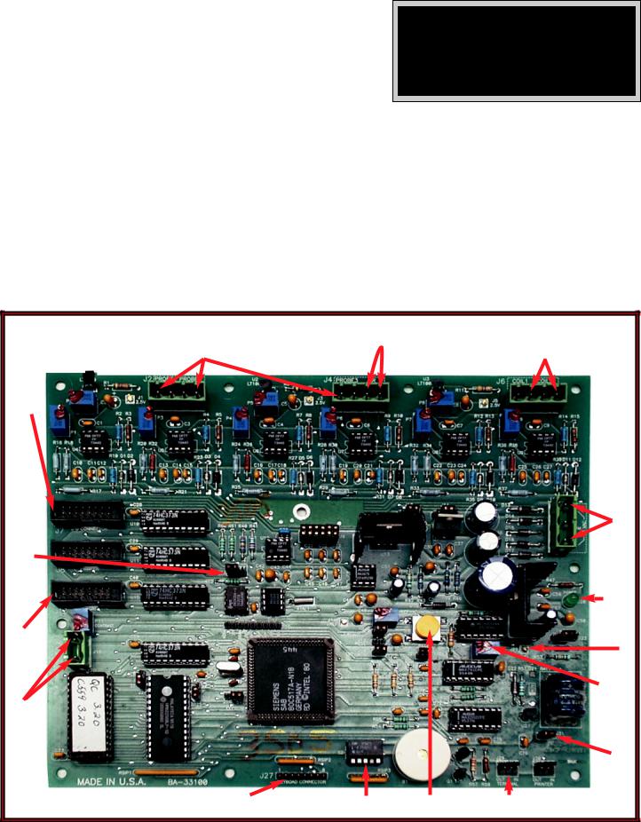
The CPU board is the microprocessor for the Quickchiller. It processes and controls all input from the product probes, air temperature sensor, the coil 1 and coil 2 RTD sensors, the LCD driver board, the keyboard touch pad, and the printer. The microprocessor has a battery that will allow the CPU board to hold a program for up to 14 days in the event of a power failure. A ribbon cable allows the relay board to communicate with the CPU board.
The CPU reset and power LED are located at the bottom part of the board (Figure 8).
NOTE: THERE IS AN RTD SENSOR BUILT INTO A CHIP TO MONITOR TEMPERATURE IN THE CPU ENCLOSURE. IF THE TEMPERATURE IN THE ENCLOSURE EXCEEDS 115 DEGREES F. (46°C), THE CONTROL WILL FAIL. THERE ARE NO SERVICEABLE PARTS ON THE CPU BOARD.
|
|
Figure 8 |
|
|
|
|
PRODUCT PROBE |
AIR SENSOR |
|
COIL 1 & COIL 2 |
|
|
1, 2, 3 |
|
|
RTD SENSORS |
|
RELAY/CPU |
RIBBON CABLE |
|
|
|
|
WRITE |
PROTECT SWITCH |
|
|
|
(J12) 24VAC |
RIBBON |
|
|
|
LEDPOWER |
|
DISPLAY |
CABLE |
|
|
P12 |
PIN PFI |
5VDC |
|
|
|
POT-TRIM |
|
|
KEYBOARD |
DIP |
CPU |
PRINTER SERIAL |
BATTERY SWITCH |
|
|
||||
|
RIBBON |
SWITCHES |
RESET |
PORT CONNECTOR |
|
|
|
|
|
|
3. |
TROUBLE SHOOTING THE CPU BOARD
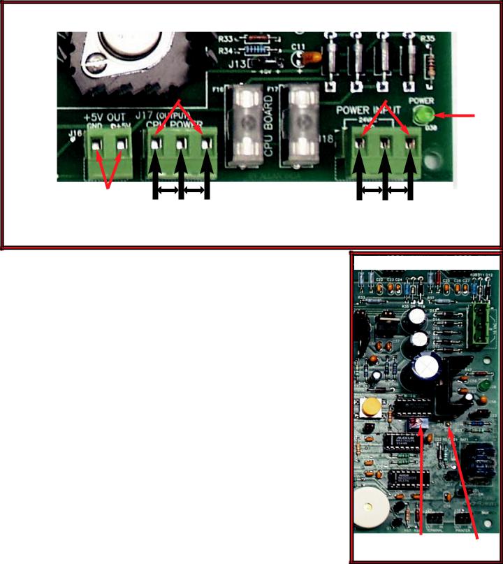
If the CPU board is suspected as the problem, open the locked CPU access door and verify the green power LED is illuminated. If the LED is not illuminated and there is 24VAC on the J12 connector across L1 and L2, the CPU board is defective and must be replaced (Figure 8). Also check for 12VAC from L1 to COM and from L2 to COM. If there is no voltage or 1/2 voltage present, check for 24VAC across the 2 outside terminals at the J17 connector on the relay board (Figure 9). If there is 24VAC on the J17 connector, the wiring from the relay board to the CPU board is defective and needs to be replaced.
Figure 9
24VAC |
|
24VAC |
|
|
|
5VDC
12VAC FROM |
12VAC FROM |
||
L1 |
TO GROUND |
L1 |
TO GROUND |
|
AND |
|
AND |
L2 |
TO GROUND |
L2 |
TO GROUND |
If there is no 24VAC across L1 and L2 on the J17 plug, check the F16 and F17 1 AMP fuses. If the fuses are good and there is no 24VAC present at J18 connector or if the green power LED on the relay board is not illuminated, the circuit breaker switch is tripped or defective. If the circuit breaker switch is turned ON and appears good, check for line voltage through the filter at the terminal block mounted at the top of the relay board enclosure. If there is line voltage at the terminal block, the transformer is defective and needs to be replaced.
If the LCD display is blank and the circuit breaker switch is turned ON, check that the LCD display ribbon cable is not cut or damaged. If it is connected properly to the LCD driver board and the pins on the board are clean, check to make certain it is plugged into the J13 connector and seated properly. If the above checks out good, power down the control by turning the circuit breaker switch OFF. Inspect chip-set U15, U11 and U10 to make certain they are seated properly. Turn the circuit breaker switch ON and check the display. If there is still no display, check to make certain the power failure threshold is set to between 1.70 and 1.85VDC.
To set the power failure threshold, locate the P12 trim-pot at the lower left-hand portion of the CPU board (Figure 10). Using a multi-meter set to the DC volts scale, place the red lead onto pin connector PFI and the black lead onto the metal board retaining nut. Adjust the trim-pot P12 until the voltage reading is between 1.70 and 1.85VDC.
Figure 10
ADJUST TRIM-POT TO RAISE THRESHOLD TO 1.70 - 1.85 VDC (P12)
LED POWER
PFI
4.

RELAY BOARD
The relay board (Figure 11) is mounted in a metal enclosure with a metal or lexan cover over it. For the QC-3 it is located behind the front grille, mounted to the left of the compressor and can be slid out for servicing. For the QC-20 it is located behind the CPU enclosure, laying flat and can be slid out for servicing. For the QC-40 it is located behind the lower grille, mounted to the left of the compressors and can be slid out for servicing. For the QC-50 it is located behind the upper grille, to the left of the compressors and can be accessed by removing the metal cover. For the QC-100 it is located inside the locked CPU enclosure at the top of the enclosure.
|
|
|
|
Figure 11 |
|
|
|
|
|
|
|
EVAPORATOR FANS |
|
|
|
|
REFRIGERANT |
|
|||
|
LEFT |
EVAPORATOR FANS |
|
DEFROST |
|
SOLENOID |
COMPRESSORS |
|
||
|
|
|
|
RIGHT |
LEFT |
|
||||
|
|
|
RIGHT |
|
HEATERS |
|
COMPRESSOR |
|||
|
|
|
|
|
|
|||||
|
|
|
|
|
|
|
|
|||
FAN FUSES |
|
|
|
|
|
|
|
|
FUSE |
|
DEFROST |
HEATER FUSES |
|
|
|
|
|
|
|
RELAYS FUSES |
HEATER SOLENOID |
|
|
|
|
|
|
|
|
|
14VDC |
DEFROST |
|
|
|
|
|
|
|
|
|
LED POWER |
|
|
RIBBON CABLE |
BEEPER |
DOOR |
5DVC |
|
CPU |
|
|
|
|
|
CONNECTOR |
|
SWITCH |
TO CPU BOARD |
POWER FUSES |
|
|
|||
|
|
24VAC |
24VAC |
|
||||||
|
|
|
|
|
|
|
|
|
||
|
|
|
|
|
TO CPU BOARD |
|
|
FROM |
|
|
|
|
|
|
|
|
|
|
|
TRANSFORMER |
|
The relay board has 6 (F1-F6) 2A fuses to protect the fans. There are 6 (F7-F12) 4A fuses to protect the defrost heaters in all Quickchillers except the QC-40 which uses 6.3 Amp fuses. All units use 2 (F13-F14) 300MA fuses to protect the refrigerant solenoids and 1 (F14) 250MA fuse to protect the compressor relays. The 2 (F16-F17) 1A fuses protect the 24 VAC power to the CPU board.
5.
 Loading...