


|
Cook, |
Hold , Smoke Ov en |
|
|
|
Man ual Control |
|
|
Models : |
|
|
|
|
767-SK |
|
|
|
1767-SK |
|
1767-SK |
|
|
|
767-SK |
|
• INST ALLATIO N |
|
|
|
||
|
• OPERATION |
|
|
|
• MAI NTENA NCE |
|
|
W164 N9221 Water Street • P.O. Box 450 • Meno monee Falls , Wiscons in 530520450 USA |
|
||
PHONE : 262.251 .380 0 • 800.558.8744 |
USA/CANADA |
FAX: 262.251.7067 • 800.329.8744 U.S.A. ONLY |
|
|
www.alto-sh aam.com |
|
|
P RINT ED IN U .S .A . |
|
MN28601 |
• 03/10 |

Delivery. . . . . . . . . . . . . . . . . . . . . . . . . . . . . . . . . . 1
Unpacking . . . . . . . . . . . . . . . . . . . . . . . . . . . . . . . . 1
Safety Procedures and Precautions . . . . . . . . . . . . 2
Installation
Installation Requirements . . . . . . . . . . . . . . . . . . 3
Clearance Requirements . . . . . . . . . . . . . . . . . . 3
Dimension Drawings. . . . . . . . . . . . . . . . . . . . . . 4
Net/Ship Weight . . . . . . . . . . . . . . . . . . . . . . . . . 4
Capacity . . . . . . . . . . . . . . . . . . . . . . . . . . . . . . . 4
Options and Accessories . . . . . . . . . . . . . . . . . . 5
Stacking Instructions . . . . . . . . . . . . . . . . . . . . . 6
Leveling . . . . . . . . . . . . . . . . . . . . . . . . . . . . . . . 7
Restraint Requirements - Mobile Equipment . . . . 7
Drip Tray Installation . . . . . . . . . . . . . . . . . . . . . 8
Electrical Specifications . . . . . . . . . . . . . . . . . . . 9
Operating Instructions
User Safety Information . . . . . . . . . . . . . . . . . . 10
Start-Up Operation . . . . . . . . . . . . . . . . . . . . . . 10
Manual Control Operation . . . . . . . . . . . . . . . . . 11
Cooking Oven Characteristics. . . . . . . . . . . . . . 11
General Holding Guidelines . . . . . . . . . . . . . . . 12
Care and Cleaning
Cleaning and Preventative Maintenance . . . . . . 13
Protecting Stainless Steel Surfaces . . . . . . . . . 13
Cleaning Agents . . . . . . . . . . . . . . . . . . . . . . . . 13
Cleaning Materials . . . . . . . . . . . . . . . . . . . . . . 13
Equipment Care . . . . . . . . . . . . . . . . . . . . . . . . 14
Clean Daily. . . . . . . . . . . . . . . . . . . . . . . . . . . . 14
Clean the Door Vents . . . . . . . . . . . . . . . . . . . . 14
Check Overall Condition of Oven . . . . . . . . . . . 14
Sanitation
Sanitation/Food Safety . . . . . . . . . . . . . . . . . . . 15
Internal Food Product Temperatures . . . . . . . . . 15
Service |
|
Thermostat/Pilot Light Sequence . . . . . . . . . . . |
16 |
Thermostat Calibration . . . . . . . . . . . . . . . . . . . |
16 |
Trouble Shooting Checklist . . . . . . . . . . . . . . . . |
17 |
Exterior Service View - 767-SK . . . . . . . . . . . . . . |
18 |
Exterior Service Parts List - 767-SK . . . . . . . . . . |
19 |
Electronic Components Service View - 767-SK . . |
20 |
Electronic Components Parts List - 767-SK . . . . . |
21 |
Cable Heating Kits - 767-SK, 1767-SK . . . . . . . . . . |
21 |
Exterior Service View - 1767-SK . . . . . . . . . . . . . |
22 |
Exterior Service Parts List - 1767-SK. . . . . . . . . . |
23 |
Electronic Components - 1767-SK . . . . . . . . . . . . |
24 |
Electronic Components Parts List - 1767-SK . . . . |
25 |
Wire Diagrams |
|
767-SK, 1PH, 120V . . . . . . . . . . . . . . . . . . . . . |
26 |
767-SK, 1PH, 208-240V . . . . . . . . . . . . . . . . . . |
27 |
767-SK, 1PH, 230V . . . . . . . . . . . . . . . . . . . . . |
28 |
1767-SK, 1PH, 208-240V . . . . . . . . . . . . . . . . . |
29 |
1767-SK, 1PH, 230V . . . . . . . . . . . . . . . . . . . . |
30 |
Warranty
Transportation Damage and Claims . . BACK COVER
Limited Warranty . . . . . . . . . . . . . . . . . BACK COVER

DELI VERY
This Alto-S haam applian ce has been |
||
thorou ghly tested and ins pect ed to ensure only the |
||
highest quality |
unit is prov ided. Upo n receipt, |
|
check for any possible shippin g dama ge and repo rt |
||
it at once to the delivering carrier. See |
||
Transp orta tio n Damage and Claims section |
||
loca ted in this manua l. |
|
|
This appliance, complete with unattac hed |
||
items and acc essories, may have been delivered in |
||
one or more packages . Chec k to ensure that all |
||
stan dard ite ms and options |
have been received |
|
with each mod el as ordered. |
|
|
Sav e all the inf orm ation |
and instruct ions |
|
pack ed with the appliance. |
Complete and return |
|
the warranty card to the factory as soo n as |
||
possib le to ensu re prom pt ser vic e in the event of a |
||
warranty parts |
and lab or claim. |
|
This manual must be read and understo od by |
||
all peop le using |
or installin g the equipment |
|
model . Contact |
the Alto-S haam service |
|
depa rtment if you have any quest ions con cer ning |
||
insta llation, operation, or mainte nance. |
||
NOTE: All claims for war ranty must include the ful l mod el number and seria l number of the unit.
UNPACK I NG
1.Carefull y remov e the applia nce from the carto n or crate.
NOTE : Do not disca rd the |
® |
carton and other |
|
packa ging material |
|
until you have |
|
inspected the unit |
|
for hidde n damage |
|
and tested it for |
|
prope r operation. |
|
2.Read all instru ctions in this manual carefu lly before initiating the installation of this appliance.
DO NOT DISCARD THIS MANUAL.
This manual is conside red to be part of the applia nce and is to be provided to the owner or manager of the busin ess or to the person responsib le for training ope rators. Additi onal man uals are availab le from the Alt o-Shaa m ser vice department .
3.Rem ove all protecti ve plastic film, packaging materi als, and access orie s from the appli anc e before connecting electric al pow er. Store any acces sori es in a convenient place for futu re use.
767-SK, 1767-SK INSTALLA TI ON/OPERA TI ON /SERVI CE MANUAL |
Pg. 1. |

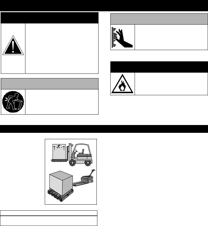
SAFETY PROC EDURES
AND PRECA UTI ONS
Knowl edg e of prop er proc edu res is essen tial to the safe opera tion of elec trically and/or gas energize d equi pment. In accorda nce with gen erally accepte d produ ct safety labeling guideline s for poten tial hazards, the following sign al wor ds and symbo ls may be used throughout this manual.
DAN GER
Used to indicate the presence of a hazard that WILL cause severe personal injury, death, or substantial property damage if the warning included with this symbol is ignored.
WA RNING
Used to indicate the presence of a hazard that CAN cause personal injury, possible death, or major property damage if the warning included with this symbol is ignored.
C AU TI ON
Used to indicate the presence of a hazard that can or will cause minor or moderate personal injury or property damage if the warning included with this symbol is ignored.
C AU TI ON
Used to indicate the presence of a hazard that can or will cause minor personal injury, property damage, or a potential unsafe practice if the warning included with this symbol is ignored.
NOTE: Used to noti fy per sonnel of installation, oper ation, or
mai ntena nce inform ation that is import ant but not hazard rela ted .
1.This appliance is intended to coo k, hold or proce ss food s for the purpose of human consumption . No other use for this applianc e is authori zed or recom mended.
2.This appliance is intended for use in comme rcial establishments where all operators are fami liar with the purpose, limitations, and ass ociated hazards of this appliance. Operati ng
instruct ion s and warnings must be read and understoo d by all operators and users.
3.Any troubleshoot ing guides , component views, and parts lists included in this manual are for general reference only and are inte nded for use by qualif ied technica l person nel.
4.This manual should be con sid ere d a permanent part of this appliance. This manual and all supplied instr uct ions, diagra ms, sche matics , parts list s, notices, and labels must remain with the appliance if the item is sold or moved to another location.
N O TE
For equipment delivered for use in any location regulated by the following directive:
DO NOT DISPOSE OF ELECTRICAL
OR ELECTRONIC EQUIPMENT WITH
OTHER MUNICIPAL WASTE.
Pg. 2. |
767-SK, 1767-SK INST ALLAT ION/OPERA TI ON /SER VICE MANUAL |
I NST ALLATIO N
DAN GE R
IMPROPER INSTALLATION,
ALTERATION, ADJUSTMENT, SERVICE, OR MAINTENANCE COULD RESULT IN SEVERE INJURY,DEATH, OR CAUSE PROPERTY DAMAGE.
READ THE INSTALLATION, OPERATING AND MAINTENANCE INSTRUCTIONS THOROUGHLY BEFORE INSTALLING OR SERVICING THIS EQUIPMENT.
C AUTION
TO PREVENT PERSONAL INJURY,
USE CAUTIONWHEN MOVING OR
LEVELING THIS APPLIANCE.
C AU TIO N
METAL PARTS OF THIS EQUIPMENT
BECOME EXTREMELYHOT WHEN IN
OPERATION. TO AVOID BURNS,
ALWAYS USE HAND PROTECTION
WHEN OPERATINGTHIS APPLIANCE.
 D AN GER
DO NOT store or use gasoline or other flammable vapors or liquids in the vicinity of this or any other appliance.
The Alto-S haa m cook and hold oven must be instal led in a
loca tion that will permit the ove n to function for its inten ded purpose and to allow
adequ ate cle aranc e for ventilation , proper clean ing, and mainte nance access.
CLEARA NCE REQUIREMENTS
3-inc hes (76mm) at the back , 2-inches (51mm) at the top, and 1-in ch (25m m) at both sides
|
SIT E INST AL L ATIO N |
1. |
The oven must be inst alled on a stable and |
|
lev el surface. |
2. |
DO NOT install this appliance in any area |
|
where it may be affected by any adv erse |
|
condi tions such as ste am, grease, dripping |
|
water, high temperatures, or any other sever ely |
|
adv erse cond itions. |
3. |
DO NOT store or use any flammable liq uids or |
|
allow flammable vapors in the vicin ity of this |
|
ove n or any othe r appliance. |
4. |
This appliance must be kep t free and clear of |
|
any com busti ble mater ials. |
5. |
This appliance must be kep t free and clear of |
|
any obs tru cti ons blocking access for |
|
mainte nance or serv ice. |
767-SK, 1767-SK INSTALLA TI ON/OPERA TI ON /SERVI CE MANUAL |
Pg. 3. |

I NST ALLATIO N
S IT E INST AL LA TIO N
|
767-SK |
|
|
|
|
1767-SK |
||||
|
|
|
|
|
|
|
28-3/16" |
|
|
|
|
28-5/8" (726mm) |
|
|
|
|
|
(716mm) |
|
|
|
|
11-5/8" |
|
|
|
|
|
12-7/8" |
|
|
|
|
|
|
|
|
|
(326mm) |
|
|
|
|
|
(295mm) |
|
|
|
|
|
|
|
|
|
|
|
|
|
|
|
|
|
|
|
|
| <![if ! IE]> <![endif]>34-7/8" (886mm) |
|
|
|
|
<![if ! IE]> <![endif]>34-1/2" (876mm) |
Electrical |
|
|
|
|
Electrical |
|
|
|
Connection |
|
|
<![if ! IE]> <![endif]>with optional bumper |
|||
Connection |
|
|
|
Shown with |
<![if ! IE]> <![endif]>54-3/4" (1390mm) |
<![if ! IE]> <![endif]>56-3/4" (1441mm) |
||||
|
<![if ! IE]> <![endif]>56-15/16" (1445mm) |
|
|
|||||||
Shown with |
|
|
Optional |
|||||||
|
|
Bumper |
||||||||
optional bumper |
|
|
||||||||
|
|
|
||||||||
| <![if ! IE]> <![endif]>54-13/16"(1376mm) |
|
|
|
|||||||
|
|
|
|
|
|
|
25-3/4" |
|
|
31-9/16" |
|
|
|
|
|
|
|
(653mm) |
|
|
(801mm) |
|
25-3/4" (654mm) |
31-3/4" (805mm) |
|
|
|
|
|
|
|
|
|
|
|
|
|
|
|
|
|
|
|
| <![if ! IE]> <![endif]>33-1/2" (851mm) with 3-1/2" casters* 28-1/4" (717mm) |
|
|
<![if ! IE]> <![endif]>30-7/8" (784mm) |
<![if ! IE]> <![endif]>(electrical connection) |
<![if ! IE]> <![endif]>62-3/8" (1583mm) |
<![if ! IE]> <![endif]>with 5" Casters |
|
|
|
<![if ! IE]> <![endif]>59-1-2" (1511mm) |
|
26-5/8" (676mm) |
26-15/16" (683mm) |
|
|
|
|
|
|
|
|
*31-13/16" (807mm) - with optional 2-1/2" casters |
|
|
|
|
23-5/8" |
|
|
24-1/8" |
||
|
|
|
|
(600mm) |
|
|
||||
*35-1/4" (894mm) - with optional 5" casters |
|
|
|
|
|
|
(613mm) |
|||
|
|
|
|
|
|
|
||||
*34-7/16" (874mm) - with optional 6" legs |
|
|
|
|
|
*60-15/16" (1548mm) - with optional 3-1/2" (89mm) casters |
||||
|
|
|
|
|
|
|
||||
|
|
|
|
|
|
|
*62-1/2" (1589mm) - with optional 6" (152mm) legs |
|||
WEIGH T |
|
|
CAPACITY PER COMPARTMEN T |
MODEL |
NET WEIGHT |
SHIPWEIGHT |
|
767-SK |
196 lb (89 kg) |
225 lb (102 kg) |
100 lb (45 kg) MAXIMUM |
1767-SK |
359 lb (163 kg) EST. |
450 lb (204 kg) |
VOLUME MAXIMUM: 53 QUARTS (67 LITERS) |
|
|
|
|
Pg. 4. |
767-SK, 1767-SK INST ALLAT ION/OPERA TI ON /SER VICE MANUAL |
|
|
I NST ALLATIO |
N |
|
|
|
||
|
|
|
|
|
|
|
|
|
|
|
|
|
|
|
|
|
|
|
SI TE I NSTA LLAT ION |
|
|
|
|
|
|
|
|
|
|
|
|
|
|
|
|
|
|
|
|
|
|
|
||
|
|
OPTIONS AND ACCESSORIE S |
|
767-SK |
1767-SK |
|
|
|
|
|
|
|
|
|
|
|
|
|
|
Bump er, Full Perime ter |
|
|
5010371 |
5010371 |
|
|
|
|
|
|
|
|
|
|
|
|
|
Car ving Holder |
PRIME RIB |
|
HL2635 |
HL2635 |
|
|
|
|
|
|
|
||||
|
|
STEAMSHIP (CAFETERIA) ROUND |
|
4459 |
4459 |
|
|
|
|
|
|
|
|
|
|
||
|
|
Cas ters - 2 RIGID, 2 SWIVEL W/BRAKE 5" (127mm ) |
|
5004862 |
STANDARD |
|
|
|
|
|
|
3-1/2" (89mm) |
|
STANDARD |
5008017 |
|
|
|
|
|
2-1/2" (64mm) |
|
5008022 |
–– |
|
|
|
|
|
|
|
|
|
|
|
|
|
Door Lock with Key |
|
|
LK-2763 |
LK-2763 |
|
|
|
|
|
|
|
|
|
|
|
|
|
Drip Pan with Drain |
|
|
14831 |
14831 |
|
|
|
|
|
|
|
|
|
|
|
|
|
Legs, 6" (152mm ), Stemme d (SET OF FOUR) |
|
5011149 |
5011149 |
|
|
|
|
|
|
|
|
|
|
||
|
|
Pan Grid, Wire - 18" X 26" PAN INSERT |
|
PN-2115 |
PN-2115 |
|
|
|
|
|
|
|
|
|
|
|
|
|
|
Pan Slides (230V ONLY) |
|
|
1010813 |
1010813 |
|
|
|
|
|
|
|
|
|
|
|
|
|
Security Panel |
|
|
5004750 |
5004750 |
|
|
|
|
|
|
|
|
|
|
|
|
|
Shelf, Stai nless Steel |
FLAT WIRE, REACH-IN |
|
SH-2324 |
SH-2324 |
|
|
|
|
|
|
|
||||
|
|
|
RIB RACK |
|
SH-2743 |
SH-2743 |
|
|
|
|
|
|
|
|
|
|
|
|
|
Stac king Hardware |
|
|
5004864 |
–– |
|
|
|
|
|
|
|
|
|
|
|
|
|
Wood Chi ps, bulk pack |
|
|
|
|
|
|
|
|
|
App le 20 lb (9 kg) |
|
WC-22543 |
WC-22543 |
|
|
|
|
|
Cherry 20 lb (9 kg) |
|
WC-22541 |
WC-22541 |
|
|
|
|
|
Hickory 20 lb (9 kg) |
|
WC-2829 |
WC-2829 |
|
|
|
|
|
Maple 20 lb (9 kg) |
|
WC-22545 |
WC-22545 |
|
|
|
|
|
|
|
|
|
|
|
767-SK, 1767-SK INSTALLA TI ON/OPERA TI ON /SERVI CE MANUAL |
Pg. 5. |
|
|
|
I NST ALLATIO |
N |
|
|
|
|
|
|
|
||
|
|
|
|
|
|
|
|
S IT E INST AL LA TIO N |
|
|
|
||
|
|
|
|
|||
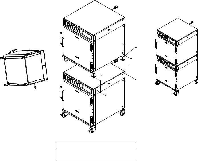
STACKING INSTR UCTIONS |
|
|
|
|||
1) |
If the two applia nces were shipped toget her from the fac tory, the top unit will have the |
|||||
|
caster s alrea dy removed. |
A stacking kit will be included wit h the shi pme nt. |
||||
|
If cast ers need to be remo ved: |
lay the unit on its back, and remove the set screw |
on each caster . Pull the |
|||
|
cast ers out of the unit. |
|
|
|
|
|
2) |
Whi le appliance is laid |
on its back , ins ert one sta cking post in each |
of the four corne rs |
|||
|
of the upper unit. Secure |
the stacking |
posts usi ng one screw and two flat wash ers that |
|||
|
com e with the stacking |
kit. |
|
|
|
|
|
Not e: The flange on the stackin g posts must face the outside of the unit. |
|
||||
3) |
Remov e the four top mounting scr ews from the low er uni t. Place the upper appl iance, |
|||||
|
whi ch has the stac kin g posts installed, |
on top of the bottom unit . Cen ter the top |
||||
|
uni t from front to back. |
Re-ins tall the four screws through the flange of the fou r |
||||
|
sta cking posts. |
|
|
|
|
|
STACKING
POSTS
CASTER SET
 SCREW
SCREW
TOP
MOUNTING
SCREWS
TOP
MOUNTING
SCREWS
Stacking Configurations
767-SK with 767-SK, 750-TH/III, 750-TH-II, 767-SK/III, or 750-S
Pg. 6. |
767-SK, 1767-SK INST ALLAT ION/OPERA TI ON /SER VICE MANUAL |

I NST ALLATIO N
S IT E |
INST |
AL LA TIO N |
A number of adjustment s are associate d with |
||
initial installation |
and sta rt-up . It is important |
|
that these adjust ments be conducted by a qualifi ed |
||
serv ice tech nician. |
Ins talla tion and startup |
|
adjustments |
are the resp ons ibili ty of the deale r or |
|
use r. These adjustment s includ e but are not
limit ed to the rmost at calibra tion, doo r adjustme nt, lev eling, elec tric al hookup and instal lati on of optional cast ers or legs.
LEVEL ING
Leve l the oven from |
|
|
to-si de and front-t o-back |
with the use of a spiri t |
|
lev el. For ove ns ins talled |
with casters, |
it is |
imp ort ant tha t the installa tion surface |
be level due |
|
to the probability of freque nt oven repositio ning.
We recomm end checking the level of the oven periodi cally to make cert ain the flo or has not shifted nor the oven move d.
NOT E: Failur e to properly level this oven can cau se improper fun ction and will result in the uneven bak ing wit h products con sist ing of semi -li quid batter.
RES TRAI NT REQUIREMENTS —MO BIL E EQUIPMENT
 WARN ING
RISK OF ELECTRIC SHOCK.
Appliance must be secured
to building structure.
Any applian ce that is not furnished with a power supply cord but that includes a set of casters must be installe d with a tether. Adequate means must be provided to limit the move ment of this
applian ce without depending on or transmit ting stress to the electr ical conduit. The foll owing requireme nts apply:
1. Casters must be a maximum height of 6" (152mm). 2. Two of the casters must be the loc king type.
3.Such mobile appliances or appliances on mobile stands must be insta lled with the use of a flexibl e connector secure d to the building structure.
A mounti ng con nect or for a restrainin g device is loca ted on the lowe r back flange of the applianc e chassi s or on an oven sta nd, approximately 18"
(457mm) from the floor. A flexible connector is not supplied by nor is it available from the fact ory.
767-SK, 1767-SK INSTALLA TI ON/OPERA TI ON /SERVI CE MANUAL |
Pg. 7. |

I NST ALLATIO N
SI TE INS TALLATIO N
DRI P TRAY INSTALLATION INSTRUCTIONS


|
Item |
Description |
Qty |
|
|
|
|
|
|
|
1 |
Double-Sided Tape |
1 |
|
|
|
|
|
|
|
2 |
Drip Tray Holder |
1 |
|
|
|
|
|
|
|
3 |
8-32 x 1/4" Phil Screw |
3 |
|
|
|
|
|
|
|
4 |
Drip Tray |
1 |
|
|
|
|
|
|
|
|
|
|
|
|
|
|
|
|
1.Poke holes through double-sided tape which is attached to the back of drip tray holder .
2.Remove backing on double-sided tape .
3.Put screws through holes and attach drip tray holder to unit.
4.Optional - apply a line of food-grade silicone caulk along top edge of drip tray holder to seal.
5.Place drip tray in drip tray holder .
 WAR NING
FAILURE TO PROPERLY INSTALL THE
DRIP TRAY CAN OR WILL CAUSE
MAJOR EQUIPMENT DAMAGE AND
WILL RESULT IN A LEAKAGE
HAZARD THAT CAN CAUSE
PERSONAL INJURY.
Pg. 8. |
767-SK, 1767-SK INST ALLAT ION/OPERA TI ON /SER VICE MANUAL |
 Loading...