

Page 1

DDEC IV APPLICAT
ION AND INSTALLATION MANUAL
5 DDEC FEATURES
Section Page
5.1 AIR COMPRESSOR CONTROL ............................................................. 5-3
5.2 ANTI-LOCK BRAKE SYSTEMS .............................................................. 5-9
5.3 CRUISE CONTROL ................................................................................ 5-13
5.4 CRUISE CONTROL FOR DRILLING/PUMPING APPLICATIONS WITH
OPTIONAL DUAL STATION CONTROL ................................................. 5-21
5.5 DIAGNOSTICS ........................................................................................ 5-23
5.6 EDM AND AIM ........................................................................................ 5-27
5.7 ELECTRONIC FIRE COMMANDER ....................................................... 5-31
5.8 ELECTRONIC SPEED SWITCH ............................................................. 5-35
5.9 ENGINE BRAKE CONTROLS ................................................................ 5-39
5.10 ENGINE PROTECTION .......................................................................... 5-45
5.11 ENGINE RATINGS .................................................................................. 5-57
5.12 ETHER START ........................................................................................ 5-61
5.13 EXTERNAL ENGINE SYNCHRONIZATION ........................................... 5-65
5.14 FAN CONTROL ....................................................................................... 5-69
5.15 FUEL ECONOMY INCENTIVE ............................................................... 5-83
5.16 GLOW PLUG CONTROLLER ................................................................. 5-85
5.17 HALF ENGINE IDLE ............................................................................... 5-89
5.18 IDLE SHUTDOWN TIMER AND VEHICLE POWER SHUTDOWN ........ 5-91
5.19 IRIS ......................................................................................................... 5-97
5.20 LOW GEAR TORQUE LIMITING ............................................................ 5-105
5.21 MAINTENANCE ALERT SYSTEM .......................................................... 5-107
5.22 MANAGEMENT INFORMATION PRODUCTS ........................................ 5-131
All information subjecttochangewithout notice. (Rev. (Rev. 3/02)) 5-1
7SA742 0203 Copyright © 2002 DETROIT DIESEL CORPORATION
Page 2

DDEC FEATURES
5.23 MARINE CONTROLS ............................................................................. 5-175
5.24 OPTIMIZED IDLE .................................................................................... 5-179
5.25 OPTIMUM LOAD SIGNAL ...................................................................... 5-185
5.26 OVERALL GOVERNOR GAIN ................................................................ 5-187
5.27 PASSMART ............................................................................................. 5-189
5.28 PASSWORDS ......................................................................................... 5-193
5.29 PRESSURE SENSOR GOVERNOR ...................................................... 5-197
5.30 PROGRESSIVE SHIFT ........................................................................... 5-203
5.31 PULSE TO VOLTAGE MODULE ............................................................. 5-209
5.32 TACHOMETER DRIVE ............................................................................ 5-213
5.33 THROTTLE CONTROL/GOVERNORS ................................................... 5-215
5.34 TRANSMISSION INTERFACE ................................................................ 5-233
5.35 TRANSMISSION RETARDER ................................................................ 5-253
5.36 VEHICLE SPEED LIMITING ................................................................... 5-255
5.37 VEHICLE SPEED SENSOR ANTI-TAMPERING .................................... 5-257
5-2 All information subject to change without notice. (Rev. (Rev. 3/02))
742 0203 Copyright © 20 02 DETROIT DIESEL CORPORATION
7SA
Page 3
DDEC IV APPLICATION AND INSTALLATION MANUAL
5.1 AIR COMPRESSOR CONTROL
Air Compressor C ontrolis an optional DDEC feature that allows DDEC to regulate engine speed
and load/unload a valve in order to maintain a requested compressor outlet air pressure for air
compressor applications.
The DDEC A ir Compressor Control Feature is available with the following software releases:
DDEC III - Release 4.0 (only)
DDEC IV - all software versions (Release 20.0 or later)
5.1.1 OPERATION
The ECM monitors the air outlet pressure while varying the engine speed and operating
load/unload a valve. The valve will be opened or closed. The desired operating pressure may be
varied by the operator, within limits preset by the OEM.
The ECM will activate the Air Compressor G overnor Controls when the digital input “Air
Compressor Load Switch” is gr ounded. Engine speed is governed based on the actual air
compressor outlet pressure versus the desired output pressure. The Air Compressor Pressure
Sensor provides a pressure signal to the ECM.
The engine response to various pressure conditions is listed in Table 5-1.
Pressure Set Point
Current outlet pressure is below the pressure set
point
Pressure in the system continues to increase and
a threshold pressure is exceeded
Current outlet pressure is above the pressure set
point
* The engine will continue to run at PTO maximumuntil the outlet pressure matches the sensor pressure.
† DDEC will open and close the loading valve as a function of pressure with hysteresis. When the pressure
reaches a programmable limit above the pressure set point the DDEC digital output will be grounded.
This output may be used to either open an air compressor vent or close the air inlet. Once the air
pressure has dropped to a lower programmable limit, the digital output will be open circuited which will
either close the vent
Engine speed increases as required up to PTO
maximum speed*
The air compressor solenoid digital output is
enabled† (opened)
Engine speed decreases as required down to the
minimum PTO speed.
Result
Table 5-1 Engine Operation with Air Compressor Controls
Each horsepower rating has an associated pressure range. Horsepower ratings are defined at time
of orde r entry. The minimum and maximum pressure setting for each of the horsepower curves is
set with the DDDL/DDR, Vehicle Ele ctronic Programming System (VEPS), or DRS. The initial
pressure set point is saved between ignition cycles.
Increase (Resume/Acceleration On)
Momentarily toggling and releasing the Increase Switch (grounding the "Resume/A
cceleration
On" digital input) increases set point pressure by 4% of the pressure range. Holding the switch in
the incr ease position (gr ounding the digital input), will increase the set point pressure at a rate of
two increments per second. Releasing the switch sets the compressor controls to
All information subject to change without notice. (Rev. (Rev. 3/02)) 5-3
7SA742
0203 Copyright © 2002 DETROIT DIESEL CORPORATION
the higher setting.
Page 4

DDEC FEATURES
Decrease (Set/Coast On)
Momentarily toggling and re leasing the decrease switch decr eases set point pressure by 4% of the
pressure range. See Figure 5-1. Holding the switch in the decrease position (grounding the digital
input), will decrease the set point pressure at a rate of two increments per second. Releasing the
switch sets the compressor controls to the lower setting.
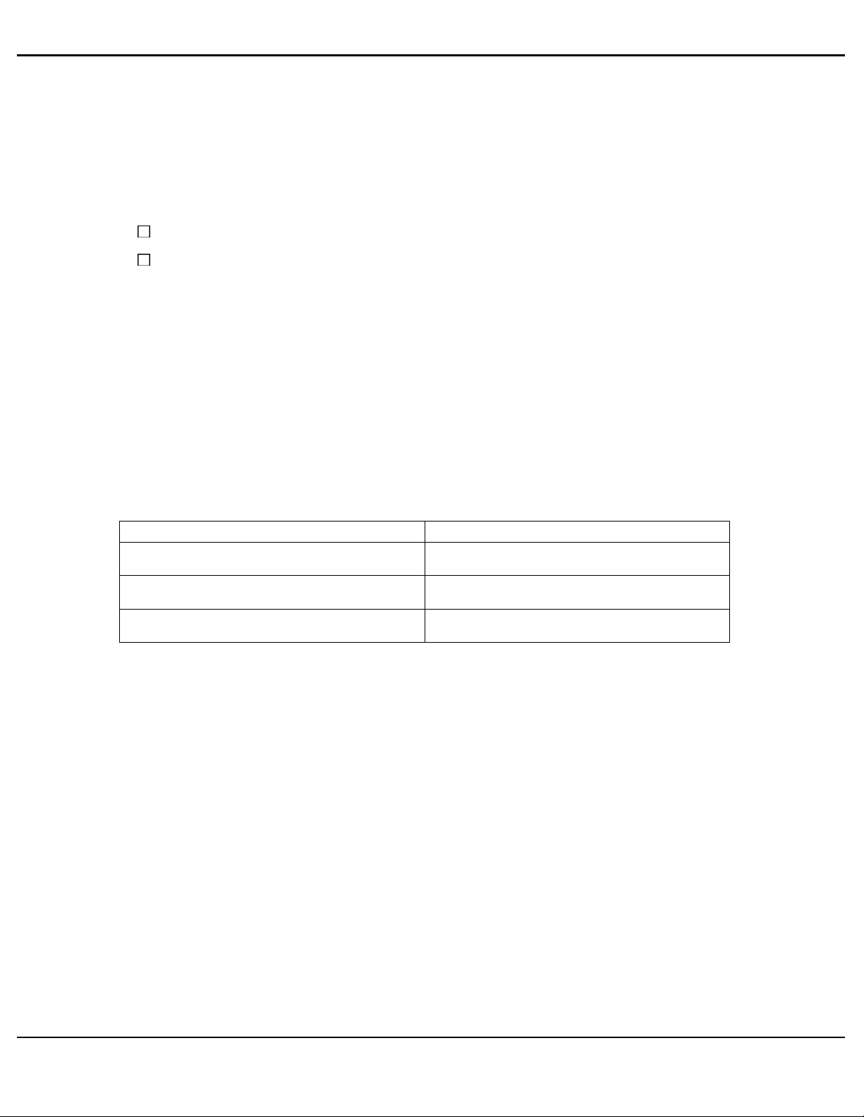
Air Compressor Load Switch
Closing (grounding) the air compressor load switch digital input activates the air compressor
control system. See Figure 5-1. Opening the air compressor load switch digital input deactivates
the air compressor control system.
Air Compressor Solenoid
When the pressure reaches a programmable limit above the pressure set point the D DEC digital
output will be grounded. This output may be use d to either open an air compressor vent or close
the air inlet. Once the air pressure has dropped to a lower programmable limit, the digital output
will be open circuited which will either close the vent or open the air inlet.
Air Compressor Shutdown
DDEC will respond to a proprietary immediate engine shut down message sent over the SAE
J1587/J1708 data link by the Electronic Display Module (EDM). This feature requires both an
EDM and an Auxiliary Information Module (AIM); refer to section 5.6 for addition information
on EDM and AIM.
Multiple Pressure Ratings
The pressure ranges are linked to the engine ratings. A pressure range can be associated with
each rating. The maximum number of engine ratings and pressure ranges is three. Choosing the
rating, with the DDR/DDDL or rating switches will automatically select the associated pressure
range. The proper 6N4D group with multiple 6N4M groups must be specified. For additional
information, contact your DDC Applications Engineer.
5-4 All information subject to change without notice. (Rev. (Rev. 3/02))
742 0203 C opyright © 2002 DETROIT DIESEL CORPORATION
7SA
Page 5
DDEC IV APPLICATION AND INSTALLATION MANUAL
5.1.2 INSTALLATION
See Figure 5-1 for the Air Compressor Control Harness.
Figure 5-1 Air Compressor Control Harness
All information subject to change without notice. (Rev. (Rev. 3/02)) 5-5
7SA742
0203 Copyright © 2002 DETROIT DIESEL CORPORATION
Page 6

DDEC FEATURES
5.1.3 PROGRAMMING REQUIREMENTS AND FLEXIBILITY
Air Compressor Controls must be specified at the time of engine order or added to the ECM
calibration by Detroit Diesel Technical Service. An Application Code (6N4C) Group must be
selected that is configured for Air Compressor Control at order entry or by contacting Detroit
Diesel Technical Service.
The digital outputs and inputs listed in Table 5-2 are required for Air Compressor Controls and
must be configured by order entry, VEPS, or the DRS.
Description Type Function Number
Set/Coast On (Decrease) Digital Input 20
Resume/Acceleration On
(Increase)
Air Compressor Load Switch Digital Input 35
Air Compressor Solenoid Digital Output 21
Table 5-2 Air Compressor Con trol Required Digital Inputs and Outputs
Digital Input 22
At order entry, the Application Code System (ACS) sets the default values for the parameters
listed in Table 5-3. These parameters may be modified using either VEPS or DRS.
Parameter Description
Air Compressor Integral Gain Integral Gain 0-128 RPM/(PSI x SEC)
Air Compressor ProportionalGain Proportional Gain 0-128 RPM/PSI
Air Compressor Pressure
Increment
Percent Pressure Increment
Choice/Display
0-50% (of fuel scale pressure
range)
Table 5-3 Air Compressor Control Parameters
Multiple pressure ratings can be selected with the use of ra ting switches. The proper 6N4D groups
with multiple 6N4M groups must be specified at engine order or by Detroit Diesel Technica l
Service. The digital inputs listed in Table 5-4 are required.
Description Type Function Number
Rating Switch #1 Digital Input 12
Rating Switch #2 Digital Input 13
Table 5-4 Multiple Pressure Ratings Required Digital Inputs
The VSG maximum and minimum RPM can be set with VEPS, DRS, DDR or DDDL as
listed in Table 5-5.
5-6 All information subject to change without notice. (Rev. (Rev. 3/02))
742 0203 C opyright © 2002 DETROIT DIESEL CORPORATION
7SA
Page 7

DDEC IV APPLICATION AND INSTALLATION MANUAL
Parameter Description
VSG Minimum RPM Sets the VSG minimum speed. Idle to VSG, Maximum RPM
VSG Maximum RPM Sets the VSG maximum speed. VSG Minimum RPM to (Rated Speed
Table 5-5 Variable Speed Gove
rnor Maximum and Minimum RPM
Choice/Display
+ LSG Droop)
The minimum and maximum pressure is set with the DDDL/DDR, DRS or VEPS as listed in
Table 5-6. There is a minimum and maximum pressure setting for each of the horsepower cur v es.
Parameter Description Range
Indicates the delta value above the current air
LOAD PSI
UNLOAD PSI
MAX RAT#1 PSI
MIN RAT#1 PSI
MAX RAT #2 PSI
MIN RAT#2 PSI
MAX RAT#3 PSI
MIN RAT #3 PSI
pressureset point thatwill initiate theair compressor
governor to reload the system.
Indicates the delta value above the current air
pressureset point thatwill initiate theair compressor
nor to unload the system.
gover
Indicates the maximum allowable air pressure set
point for engine rating #1
Indicates the minimum allowable air pressure set
point for engine rating #1.
Indicates the maximum allowable air pressure set
point for engine rating #2.
Indicates the minimum allowable air pressure set
point for engine rating #2.
Indicates the maximum allowable air pressure set
point for engine rating #3.
Indicates the minimum allowable air pressure set
point for engine rating #3.
0toUNLOADPSI
LOAD PSI to 31 PSI
MIN RAT#1 to 999 PSI
0toMAXRAT#1
MIN RAT#2 to 999 PSI
0toMAXRAT#2
MIN RAT#3 to 999 PSI
0toMAXRAT#3
Table 5-6 Air Compressor Parameters
5.1.4 INTERACTION WITH OTHER FEATURES
Air Compressor Control may not be used with Cruise Control or the Pressure Sensor Governor.
A proprietary immediate engine shut down message for immediate air compressor shutdown is
sent over the SAE J1587/J1708 data link by the EDM. This feature requires both an EDM and an
AIM; refer to section 5.6 for addition information on EDM and AI M.
All information subject to change without notice. (Rev. (Rev. 3/02)) 5-7
7SA742
0203 Copyright © 2002 DETROIT DIESEL CORPORATION
Page 8

DDEC FEATURES
THIS PAGE INTENTIONALLY LEFT BLANK
5-8 Allinformation subject to change without notice. (Rev. (Rev. 3/02))
742 0203 Co pyri ght © 2002 DETROIT DIESEL CORPORATION
7SA
Page 9

DDEC IV APPLICATION AND INSTALLATION MANUAL
5.2 ANTI-LOCK BRAKE SYSTEMS
Anti-lock Brake Systems (ABS) are electronic systems that monitor and control wheel speed
during braking. The systems are compatible with standard air brake systems. The system
monitors wheel speed at all times, and controls bra k ing during emergency situations. Vehicle
stability and control are impr oved by reducing wheel lock during braking.
5.2.1 OPERATION
The ECM transmits engine data via SAE J1587, SAE J1922, or SAE J1939. Anti-lock brake
systems monitor data on one or more of these communication links. In the event that an excessive
wheel spin is de tected, the ECM receives a message from the ABS requesting a 0% output torque
limit. The message is transmitted on SAE J1922 or SAE J1939.
SAE J1922 and SAE J1939 both implement the same message set. The difference being hardware
and performance. SAE J1922 transmits and rec eives data at 9.6 K baud while SAE J1939
transmits/receives data at 250 K baud. SAE J1939 has a much higher bit rate so messages reach
their de stination very quickly nearly eliminating the latency found with SAE J1922.
SAE J1922 is enabled on all DDEC IV ECMs. SAE J1939 is enabled on a ll DDEC IV ECMs
(Release 24.0 or later). ECMs prior to Release 24.0 must be configured if SAE J1939 is required.
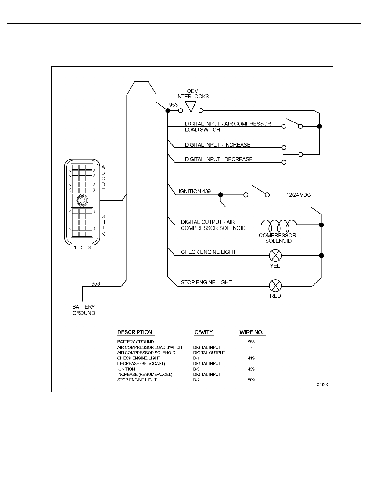
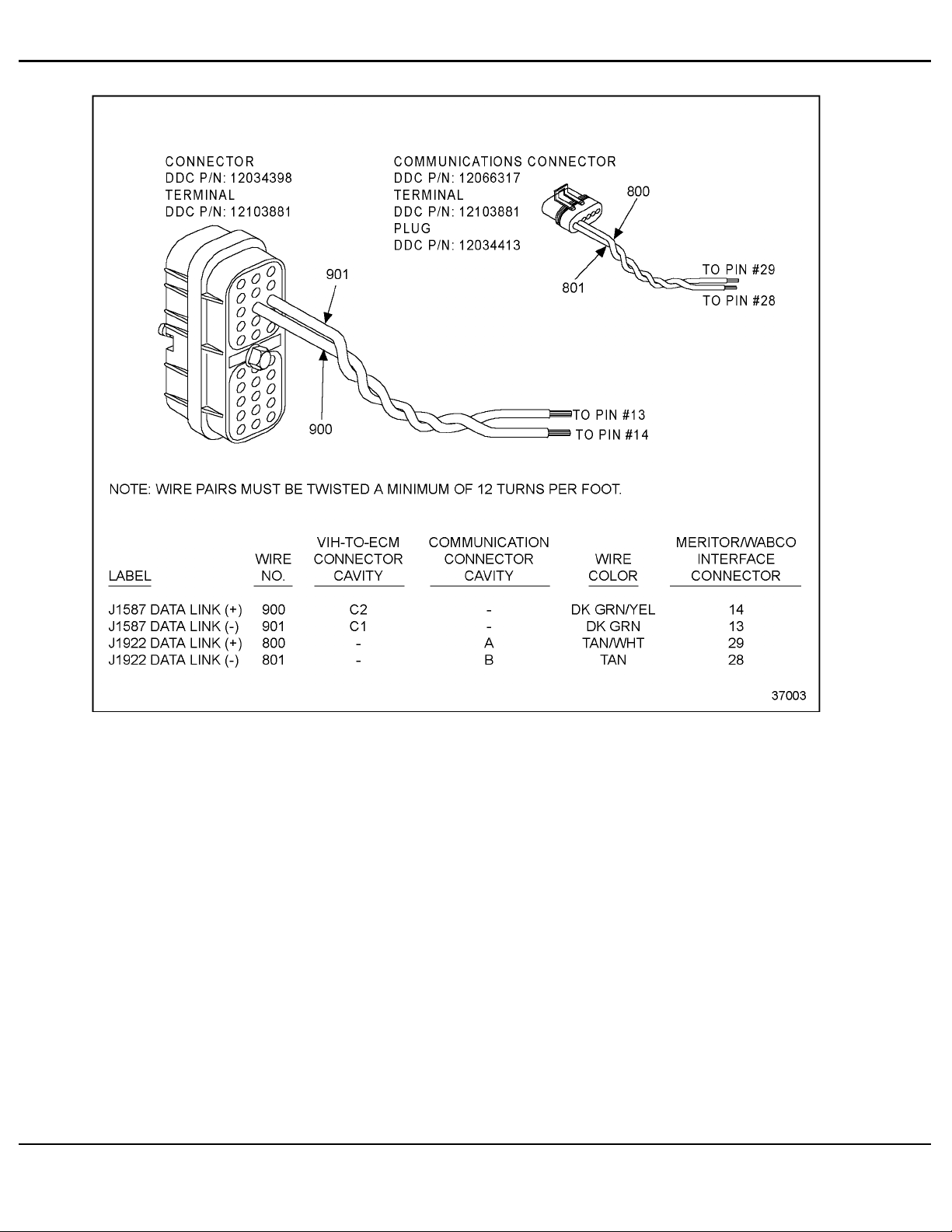
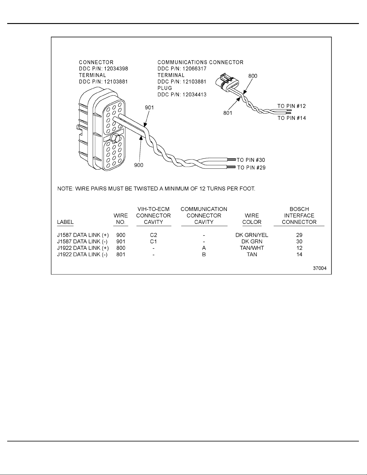
See F igure 5-2 and Figure 5-3 for interface with Meritor/WABCO and Bosch respectively.
All information subject to change without notice. (Rev. (Rev. 3/02)) 5-9
7SA742
0203 Copyright © 2002 DETROIT DIESEL CORPORATION
Page 10
DDEC FEATURES
Figure 5-2 Meritor/WABCO ABS/ATC Interface
5-10 All information subject to change without notice. (Rev. (Rev. 3/02))
742 0203 C opyright © 2002 DETROIT DIESEL CORPORATION
7SA
Page 11
DDEC IV APPLICATION AND INSTALLATION MANUAL
Figure 5-3 Bosch ABS/ATC Interface
All information subject to change without notice. (Rev. (Rev. 3/02)) 5-11
7SA742
0203 Copyright © 2002 DETROIT DIESEL CORPORATION
Page 12

DDEC FEATURES
THIS PAGE INTENTIONALLY LEFT BLANK
5-12 All information subject to change without notice. (Rev. (Rev. 3/02))
742 0203 Co pyri ght © 2002 DETROIT DIESEL CORPORATION
7SA
Page 13

DDEC IV APPLICATION AND INSTALLATION MANUAL
5.3 CRUISE CONTROL
Cruise Control is ava ilable with any DDEC engine. Cruise Control will operate in either Engine
or Vehicle Speed Mode and maintain a targeted speed (M PH or RPM) by increasing or decreasing
fueling. The targeted speed can be selected and adjusted with dash-mounted switches. Up to five
digital inputs are required (four for automatic transmission) for Cruise Control operation and a
digital output is optional (refer to section 4.1.1 for additional information on digital inputs). A
Vehicle Speed Sensor (VSS) is required for Vehicle Speed Cruise Control.
5.3.1 OPERATION
There are two types of Cruise Control: Engine Speed Cruise Control and Vehicle Speed Cruise
Control.
Engine Speed Cruise Control
Power is varied under Engine Speed Cruise Control to maintain constant engine speed. Vehicle
speed will vary depending on powertrain components. Engine Speed Cruise Control does not
need a VSS. Engine Speed Cruise Control cannot be used with automatic transmissions.
Vehicle Speed Cruise Control
Vehicle Speed Cruise is enabled when "Enable Cruise" and a Vehicle Speed Sensor (VSS) are
installed. Engine speed and power are varied under Vehicle Speed Cruise Control to maintain the
set vehicle speed. The maximum Cruise Control speed cannot exceed the programmed maximum
Vehicle Speed Limit (when programmed). The vehicle speed must be above 20 MPH and the
engine speed above 1,100 RPM (1,000 RPM for on-highway 1999 model year or later engines)
to set Cruise Control.
This type of Cruise Control is required when either of the following conditions exists:
Vehicle Speed Limiting -- Vehicle Speed Cruise Control is mandatory if the vehicle speed
limit is programmed and Cruise Control is desired. This will prevent the ECM from
fueling the engine at speeds greater than the vehicle speed limit.
Automatic Transmissions -- Vehicle Speed Cruise Control must be selected if the vehicle is
equipped with an automatic transmission. This will ensure proper transmission upshifts
while in Cruise Control. Refer to the transmission manufacturer's manual for more
information and see the Vehicle Interface Harness schematic.
Cruise c ontrol can be overridden at any time with the foot pedal if the vehicle is not operating at
the programmed Vehicle speed Limit.
Smart Cruise
The Eaton®Smart Cruise™ system will send a "he art beat" message on the SAE J1939 Data Link.
Manual C ruise Control and Smart Cruise will be disabled if the message is not received over the
data link or the message indicates that there is a failure in Smart Cruise. To regain manual control,
the driver must toggle the Cruise Master Switch twice within 10 seconds.
®
Eaton
All information subject to change without notice. (Rev. (Rev. 3/02)) 5-13
7SA742
and Smart Cruise™ trademarks of the Eaton Corporation.
0203 Copyright © 2002 DETROIT DIESEL CORPORATION
Page 14

DDEC FEATURES
This feature is available with Release 27.0 or later. Smart Cruise must be configured by VEPS
(Release 27.0 or later), WinVeps (Release 2.0 or later) or the DRS. F or additional information
on Smart Cruise, contact Eaton Corporation.
Cruise Enable
Cruise Control is enabled, but not active when the Cruise Control Enable digital input is switche d
to battery ground.
Set / Coast On
Set: Cruise Speed is set by momentarily contacting the switch to the ON position
(switching the digital input to battery ground). Cruise Control will become
active a nd maintain the engine or vehicle speed present at the time.
Coast: When Cruise Control is active, the Set/Coast input can
be used to reduce
power and speed by toggling the switch. Momentarily toggling a nd releasing
the Set/Coast switch will decrease the set point by 1 MPH increments for
Vehicle Speed Cruise Control and 25 RPM increments
for Engine Speed
Cruise Control. Holding the Set/Coast will decrease the set point by 1 MPH
per second (Vehicle Spee d CC) or 25 RPM per seconds (Engine Speed CC).
When released the Cruise Control set point will
be at the new speed.
Resume / Accel On
Resume: If Cruise Control has been disabled with the service brake or the clutch switch,
momentary contact to the ON position (switching the input to battery ground)
restores the previously set cruise speed.
Accel: When Cruise Control is active, the Resume/Accel input c an be used to increase
power and speed by toggling the switch. Momentarily toggling and releasing the
Resume/Accel switch will increase the set point by 1 MPH increments for Vehicle
Speed Cruise Control and 25 RPM increments for Engine Speed Cruise Control.
Holding the Resume/Accel will increase the set point by 1 MPH per second
(Vehicle Speed CC) or 25 RPM per seconds (Engine Speed CC). When released
the Cruise Control set point will be at the new speed.
5-14 All information subject to change without notice. (Rev. (Rev. 3/02))
742 0203 C opyright © 2002 DETROIT DIESEL CORPORATION
7SA
Page 15

DDEC IV APPLICATION AND INSTALLATION MANUAL
Clutch Released (Manual Transmissions)
This input indicates that the clutch is released and is used for suspending Cruise Control and
Auto Resume.
When the clutch is released, the input is at battery ground. Cruise Control is suspended if the
clutch is depressed once. If the clutch is depressed twice within three seconds, Cruise Control
is automatically resumed.
NOTE:
When engine brake is configured and auto resume is enabled, the first time the clutch
is depressed to suspend Cruise Control, the engine brakes will be delayed for three
seconds.
The digital input logic for the Clutch Switch disables Cruise Control in the unlikely event of a
broken clutch switch wire.
Service Brake Released (Automatic and Manual Transmissions)
This input indicates that the brake is released when switched to battery ground. If the bra ke is
activated, then the input is not grounded and Cruise Control is suspended. Cruise Control is
resumed by using the Resume/Accel Switch.
The input logic for the Brake Switch disables Cruise C ontrol in the unlikely event of a broken
brake switch wire.
5.3.2 INSTALLATION
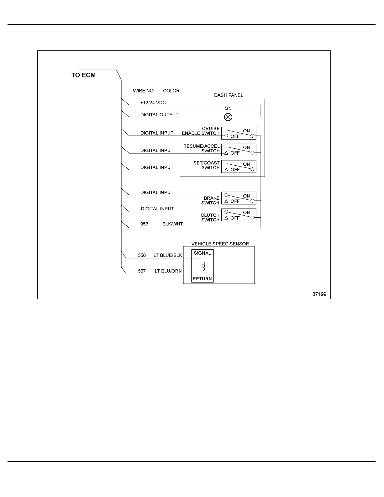
The following is a list of switches that are required for Cruise Control operation.
Cruise Enable Switch
Brake Switch
Clutch Switch -- optional for automatic transmissions
Set/Coast Switch
Resume/Accel Switch
Cruise Active Light -- optional
All information subject to change without notice. (Rev. (Rev. 3/02)) 5-15
7SA742
0203 Copyright © 2002 DETROIT DIESEL CORPORATION
Page 16
DDEC FEATURES
See Figure 5-4 for a diagram of the Cruise Control circuit.
Figure 5-4 Cruise Control Circuit
5-16 All information subject to change without notice. (Rev. (Rev. 3/02))
742 0203 C opyright © 2002 DETROIT DIESEL CORPORATION
7SA
Page 17

DDEC IV APPLICATION AND INSTALLATION MANUAL
5.3.3 PROGRAMMING REQUIREMENTS AND FLEXIBILITY
To configure an engine f or Cruise Control, the digital inputs, output and VSS settings listed in
Table 5-7 must be selected either with the Vehicle Electronic Programming System (VEPS), the
DDEC Reprogramming System (DRS) or on engine order entry. The required and optional
digital inputs and outputs are listed in Table 5-7.
Description Type Function Number
Service Brake Released Digital Input 17
Set/Coast Digital Input 20
Resume/Accel Digital Input 22
Cruise Control Enable Digital Input 23
Clutch Released
(required for manual transmissions)
Cruise Control Active Light
(optional for Cruise Control)
Table 5-7 Cruise Control Related Digital Input and Output Signals
Digital Input 18
Digital Output 11
AVeh
icle Speed Sensor must be configured for Vehicle Speed Cruise Control.
Refer to section 3.14.25, "Vehicle Speed Sensor," for additional inf ormation.
If Eaton Smart Cruise is installed on the ve hicle, the feature as listed in Table 5-8 must be
abledbyVEPSorDRS.
en
Parameter Description
Adaptive Cruise Control
(Smart Cruise)
Enables or disables the Smart Cruise Control feature. YES, NO
Choice
Table 5-8 Smart Cruise Parameter
The Cruise Control parameters listed in Table 5-9 can be set by order entry, DDR, DDDL, the
DRS, or VEPS.
All information subject to change without notice. (Rev. (Rev. 3/02)) 5-17
7SA742
0203 Copyright © 2002 DETROIT DIESEL CORPORATION
Page 18

DDEC FEATURES
Parameter Description Range
CRUISE CONTROL
MIN CRUISE SPEED Sets the maximum cruise speed in MPH or KPH.
MAX CRUISE MPH or KPH Sets the maximum cruise speed in MPH or KPH.
AUTO RESUME
CRUISE SWITCH VSG
INITIAL VSG SET SPEED Sets the cruise switch VSG initial set speed.
RPM INCREMENT Sets the cruise switched VSG RPM increment. 1to255RPM
CRUISE/ENGINE BRAKE
FEATURE
CRUISE/ENGINE BRAKE
ACTIVATION SPEED
ENG BRAKE INCREMENT
MPH or KPH
MAX OVERSPEED LIMIT
MAX SPEED NO FUEL
Enables or disables the vehicle speed Cruise
Control feature.
20 MPH to MAX
MIN CRUZ to Vehicle
Speed Limit or 127 mph
Enables or disables the automatic Cruise Control
set speed resume feature.
Enables or disables the cruise switch VSG set
speed feature.
VSG MIN RPM to
VSG MAX RPM
Enables or disables the feature that allows the
engine brake to be used while on Cruise Control
if the vehicle exceeds the cruise set speed.
Sets the additional speed before the engine
brake is applied to slow down the vehicle. The
engine brake is activated at low level unless the
operator has turned off the engine brakes with
the dash board switches.
Sets the additional incremental speed that must
be reached before the engine brake will activate
the medium and/or high level of retardation.
Sets the vehicle speed above which a diagnostic
code will be logged if the driver fuels the engine
andexceedsthislimit.Enteringa0willdisable
this option.
Sets the vehicle speed above which a diagnostic
code will be logged if the vehicle reaches this
speed without fueling the engine. Entering a 0
will disable this option.
YES, NO
CRUZ SPD
if VSL = NO
YES, NO
YES, NO
YES, NO
0to10MPH
1to5MPH
0to127MPH
0to127MPH
Table 5-9 Cruise Control Parameters
5.3.4 DIAGNOSTICS
Two faults (SID 216 FMI 14 and PID 86 FMI 14) will be logged simultaneously if Smart Cruise
is enabled and the data is not being received, the received data is ba d or the Smart Cruise unit has
been removed.
If these faults are received in addition to an SAE J1939 Data Link failure (SID 231 FMI 12) , then
the problem is with the SAE J1939 Data Link itself.
5-18 All information subject to change without notice. (Rev. (Rev. 3/02))
742 0203 C opyright © 2002 DETROIT DIESEL CORPORATION
7SA
Page 19

DDEC IV APPLICATION AND INSTALLATION MANUAL
5.3.5 INTERACTION WITH OTHER FEATURES
The Cruise Control logic i s also used with the DDEC Pressure Sensor Governor in fire trucks.
Both systems cannot be configured on the same engine. Refe r to section 5.29 for more
information on the Pressure Sensor Governor. DDEC can be configured to allow the engine
brakes to a ctivate during Cruise Control operation.
NOTE:
Cruise Control maximum speed cannot exceed the vehicle speed limit.
All information subject to change without notice. (Rev. (Rev. 3/02)) 5-19
7SA742
0203 Copyright © 2002 DETROIT DIESEL CORPORATION
Page 20

DDEC FEATURES
THIS PAGE INTENTIONALLY LEFT BLANK
5-20 All information subject to change without notice. (Rev. (Rev. 3/02))
742 0203 Co pyri ght © 2002 DETROIT DIESEL CORPORATION
7SA
Page 21

DDEC IV APPLICATION AND INSTALLATION MANUAL
5.4 CRUISE CONTROL FOR DRILLIN G/PUMPING
APPLICATIONS WITH OPTIO NAL DUAL STATION
CONTROL
Cruise control for drilling/pumping applications is an optional DDEC feature that allows the
setting of a targeted engine speed and a easy return to the targeted speed from idle.
For example, petroleum mud pumps are used to supply fluid to a drilling bit when a well is being
drilled. The operator will carefully adjust engine speed until he/she achieves the desired pumping
rate. The optimum speed will vary from job to job. The operator will continue until a new section
of drilling pipe must be added. At that point, the engine must be brought back to idle and the
transmission or clutch disengaged while new pipe is threaded in place. The operator can then
bring the engine back up to operating speed and continue the drilling and pumping operation.
5.4.1 OPERATION
This feature allows the operator to set an engine speed during the drilling and pumping process,
drop to idle speed, and then return to the original speed. Returning to the original set speed is
desirable since it has been carefully dialed in by the operator and is ideal for the particular job.
The Engine Speed Cruise Control feature would work to provide the desired engine set speed for
the pumping operation, but it is not configured to resume speed from engine idle.
This process operates as follows:
1. Start the engine, idle, and warm up.
2. Engage the ALT_MIN_VSG Switch - engine goes to ALT_MIN_VSG speed (e.g. 650
rpm).
3. Engage the Cruise Enable Switch.
4. Adjust the hand throttle to the desired speed, e.g. 1700 rpm.
5. Engage set/coast - sets speed to the desired speed, 1700 rpm.
6. Adjust the hand throttle back to idle position.
7. When the need to add pipe arises, engage the brake switch. The engine drops to 650 r pm.
8. When ready to continue, engage Resume/Accel and the spee d returns to 1700 rpm.
All information subject to change without notice. (Rev. (Rev. 3/02)) 5-21
7SA742
0203 Copyright © 2002 DETROIT DIESEL CORPORATION
Page 22

DDEC FEATURES
5.4.2 PROGRAMMING REQUIREMENTS & FLEXIBILITY
The hardware and software configuration include the proper 6N4C group for VSG engine
governing such as 06N04C0720 a nd customer selectable parameters.
The customer selectable parameters settings are listed in Table 5-10.
Parameter Description
Cruise Control Enable Enables the engine speed cruise control feature. YES
Alternate Minimum VSG Sets the Alternate Minimum VSG speed
(set above the idle speed)
Setting
650 RPM
Table 5-10 Customer Selectable Parameters
The digital inputs listed in Table 5-11 must be programme d.
Description Type Function Number
Cruise Enable Digital Input 23
Set/Coast Digital Input 20
Resume/Accel Digital Input 22
Service Brake Digital Input 17
Alt Min VSG Digital Input 16
Table 5-11 Digital Inputs
5.4.3 DUAL STATION CONTROLS
This feature will also work with dual control stations. The operator has the capability of starting
the engine at Station 1 mounted near the engine, follow the operation procedure above, and while
at the desired operating speed, switch to throttle Station 2 and adjust engine speed remotely, if
desired. The operator could then switch back to Station 1 when pipe was to be added.
For dual station controls, the digital inputs listed in Table 5-10 are required in addition to the
digital inputs listed in Table 5-12.
Description Type Function Number
VSG Station Change Digital Input 33
VSG Station Change C omplement Digital Input 34
Table 5-12 Additional Dual Station Control Digital Inputs
For additional installation information on VSG Dual Station Controls, refer to section, 4.31
"Throttle Controls/Governors".
5-22 All information subject to change without notice. (Rev. (Rev. 3/02))
742 0203 C opyright © 2002 DETROIT DIESEL CORPORATION
7SA
Page 23
DDEC IV APPLICATION AND INSTALLATION MANUAL
5.5 DIAGNOSTICS
Diagnostics is a standard feature of the DDEC system. The purpose of this feature is to provide
information for problem identification and problem solving in the form of a code. The ECM
continuously performs self diagnostic checks and monitors the other system components.
Information for problem identification and problem solving is enhanced by the detection of faults,
retention of fault codes and separation of active from inactive codes.
5.5.1 OPERATION
The e ngine-mounted ECM includes control logic to provide overall engine management. System
diagnostic checks are made at ignition on and continue throughout all engine operating modes.
Sensors provide information to the ECM regarding various engine and vehicle performance
characteristics. The information is used to regulate engine and vehicle per forma nce, provide
diagnostic information, and activate the engine protection system.
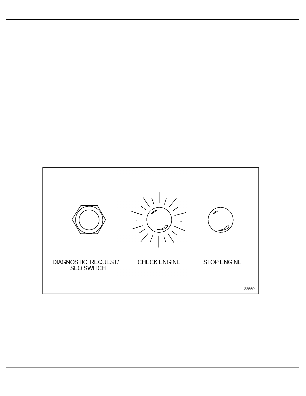
Instrument panel warning lights (see Figure 5-5), the Check Engine Light (CEL) and the Stop
Engine Light (SEL), warn the engine operator. The CEL is an amber light and the SEL is a
red light.
Figure 5-5 Typical Diagnostic Request/SEO Switch and Warning Lights
All information subject to change without notice. (Rev. (Rev. 3/02)) 5-23
7SA742
0203 Copyright © 2002 DETROIT DIESEL CORPORATION
Page 24

DDEC FEATURES
The C EL is illuminated and a code is stored if an electronic system fault occurs. This indicates
the pr oblem should be diagnosed as soon as possible. The ECM illuminates the CEL and SEL
and stores a malfunction code if a potentially engine damaging fault is detected. Th ese codes
can be accessed in one of four ways:
Using the Diagnostic Data Reader (DDR)
Flashing the CEL and SEL with the Diagnostic Request Switch (may be combined with
Stop Engine Override switch, see Figure 5-5)
Using the Detroit Diesel Diagnostic Link™ (DDDL) PC software package
By ProDriver®, Electronic Fire Commander™, Electronic Display Module (EDM), or
other display
There are two types of diagnostic codes:
An active code - a fault present at the time when checking for codes
An inactive code - a fault which has previously occurred; inactive codes are logged into
the ECM and time stamped with the following information:
First occurrence of each diagnostic code in engine hours
Last occurrence of each diagnostic code in engine hours
Total time in seconds that the diagnostic code was active
5-24 All information subject to change without notice. (Rev. (Rev. 3/02))
742 0203 C opyright © 2002 DETROIT DIESEL CORPORATION
7SA
Page 25
DDEC IV APPLICATION AND INSTALLATION MANUAL
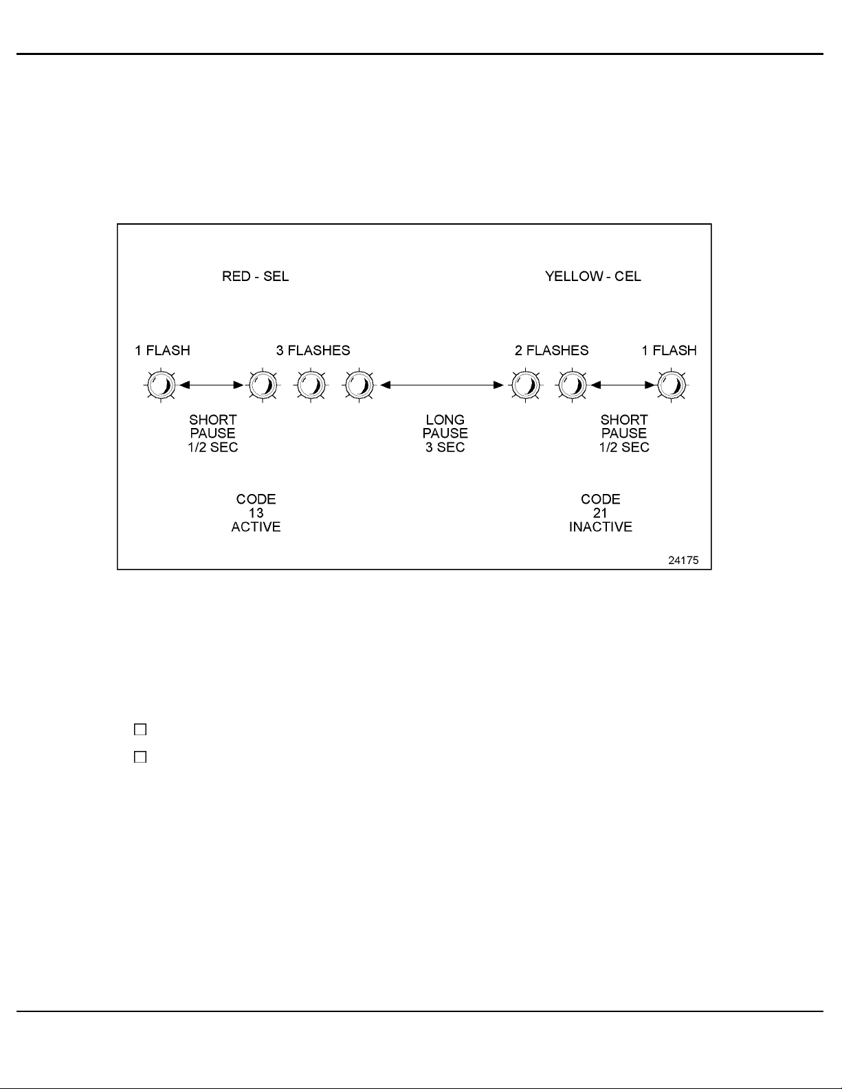
Diagnostic Request Switch
The Diagnostic Request Switch is used to activate the CEL/SEL to flash codes. Active codes are
flashed on the SEL and inactive codes are flashed on the CEL (see Figure 5-6). Inactive c odes are
flashed in numeric al order, a ctive codes are flashed in the order received, most recent to least
recent. The Diagnostic Request Switch can also be used as the Stop Engine Override (SEO)
Switch. The codes are flashed out of the ECM connected to the switch.
Figure 5-6 Flash Codes
NOTE:
For multi-ECM installations, the Diagnostic Request Switch and SEO are combined on
the master ECM. All receiver ECMs have a separate Diagnostic Request Switch.
The Diagnostic Request Switch is used to flash codes in the following circumstances:
The engine is not running a nd ignition is ON
The engine is idling
In both circumstances, activating and holding the Diagnostic Request Switch will flash out the
diagnostic codes.
All information subject to change without notice. (Rev. (Rev. 3/02)) 5-25
7SA742
0203 Copyright © 2002 DETROIT DIESEL CORPORATION
Page 26

DDEC FEATURES
Diagnostic Request Switch/Stop Engine Override
If no separate Diagnostic Request Switch is configured, the SEO Switch serves as both a
Diagnostic Request Sw itch and an SEO Switch.
The Diagnostic Request/Stop Engine Override Switch is used to flash codes in the following
circumstances:
The engine is not running and ignition is on
The engine is idling
In both circumstances, activating and releasing the switch will flash out the diagnostic codes;
activating and releasing the switch a second time will stop the ECM from flashing the diagnostic
codes. Codes will also cease flashing if the engine is no longer at idle. The codes are flashed out
of the ECM connected to the switch.
NOTE:
For multi-ECM installations, the Diagnostic Request Switch and SEO Switch are
combined on the master ECM. All receiver ECMs have a separate Diagnostic Request
Switch.
5.5.2 DEFINITIONS AND ABBREVIATIONS
Parameter Identification Character (PID): A PID is a single byte character used in SAE J1587
messages to identify the data byte(s) that follow. PIDs in the range 0-127 identify single byte
data, 128-191 identify double byte data, and 192-253 identify data of varying length.
Subsystem Identification Character (SID): A SID is a single byte cha racter used to identify
field-repairable or replaceable subsystems for which failures can be detected or isolated. SIDs are
used in conjunction with SAE standard diagnostic codes defined in SAE J1587 within PID 194.
Failure Mode Identifier (FMI): The FMI describes the type of failure detected in the subsystem
and identified by the PID or SID. The FMI and either the PID or SID combine to form a given
diagnostic code defined in SAE J1587 within PID 194.
Flashing Codes: Provides a two digit number (see Figure 5-6). This code may cover several
specific faults. It is provided to advise the operator of the general severity of the fault so the
operator can decide if engine operation can continue without damaging the engine.
Refer to Appendix A for a list of codes, the code number when flashed, the SAE J1587 number
and a description of each code.
5-26 All information subject to change without notice. (Rev. (Rev. 3/02))
742 0203 C opyright © 2002 DETROIT DIESEL CORPORATION
7SA
Page 27
DDEC IV APPLICATION AND INSTALLATION MANUAL
5.6 EDM AND AIM
The Construction and Industrial Electronic Display Module (EDM) and Auxiliary Information
Module (AIM) are the two components which comprise the Detroit Diesel Construction and
Industrial Electronic Display system for engine and equipment parameters.
5.6.1 OPERATION
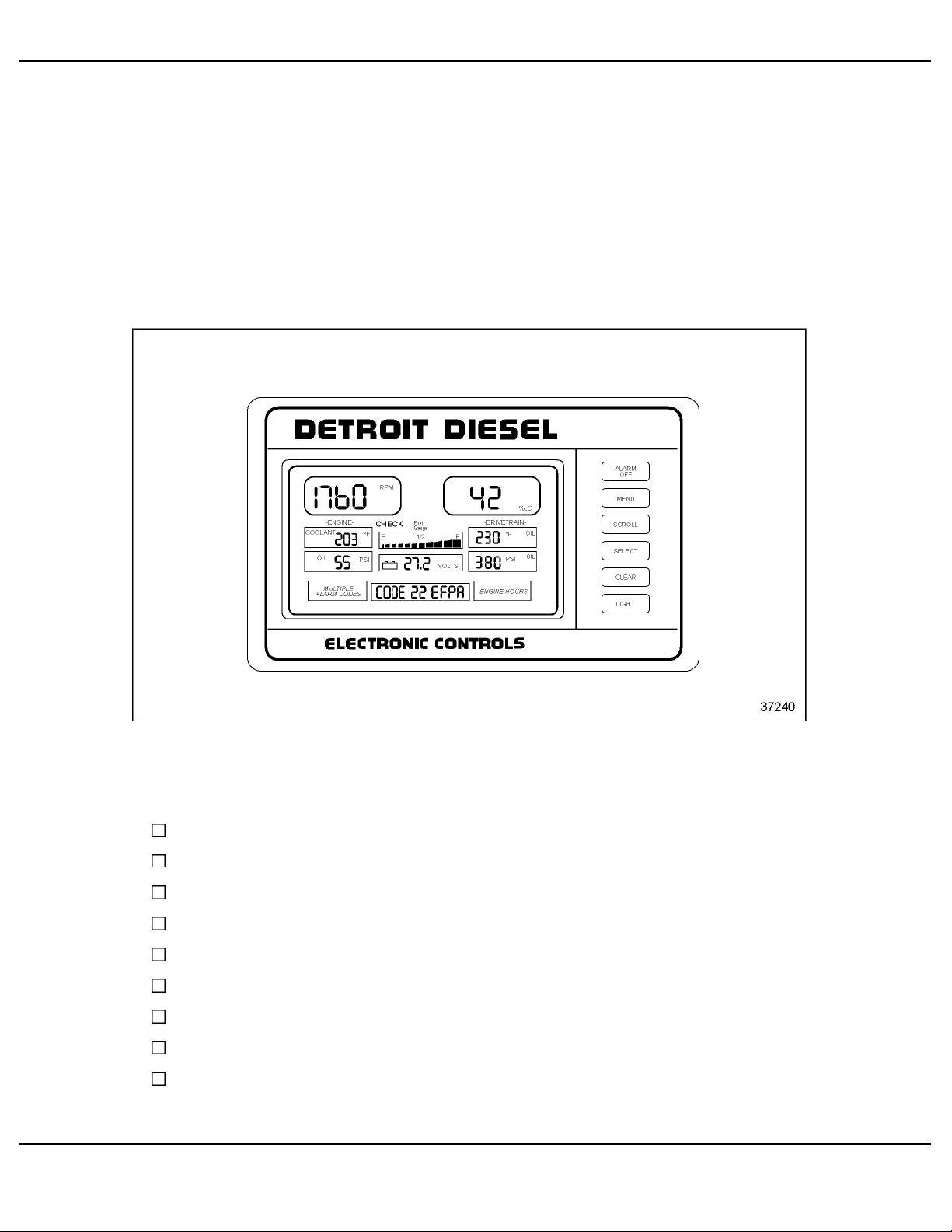
The EDM (see Figure 5-7) m ay be used alone to display engine parameters or in conjunction with
the AIM to display additional equipment parameters. AIM cannot be used without the EDM.
Figure 5-7 Electronic Display Module
The EDM will display the following parameters at all times if the sensor is installed on the
equipment:
Engine RPM
Engine Coolant or Oil Temperature
(Oil Temperature only when coolant temperature is unavailable from the ECM)
Engine Oil Pressure
ECM Battery Voltage or Auxiliary Current (Requires AIM) - (Battery Voltage display)
Vehicle Speed or Auxiliary Pump Pressure or Engine Load
Equipment Temperature or Pressure (Requires AIM)
Equipment Temperature or Pressures (Requires AIM) or Engine Turbo Boost Pressure
Fuel Level (Requires AIM)
All information subject to change without notice. (Rev. (Rev. 3/02)) 5-27
7SA742
0203 Copyright © 2002 DETROIT DIESEL CORPORATION
Page 28
DDEC FEATURES
Check and Stop Indicators
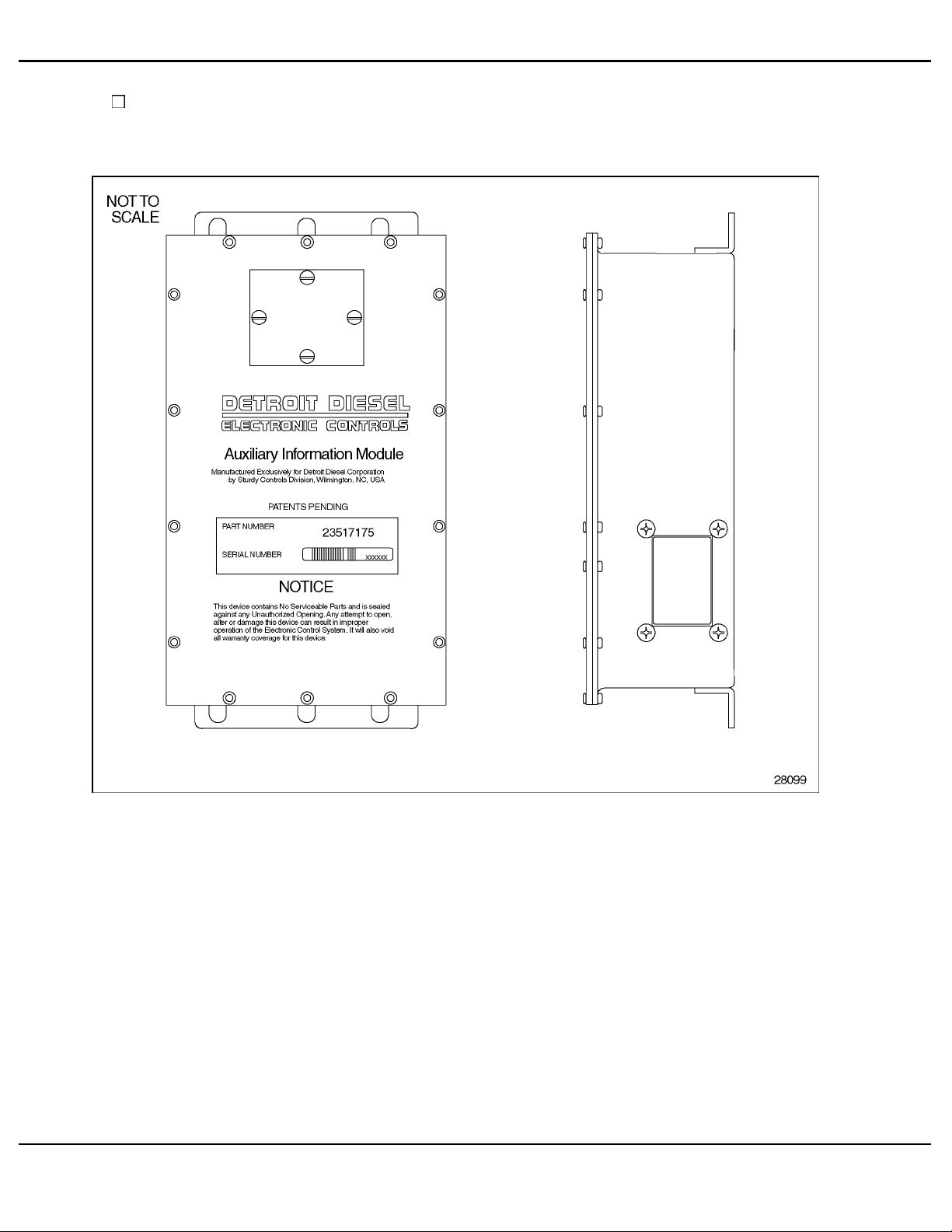
The AI M (see Figure 5-8) is used in conjunction with the EDM to display additional equipment
parameters.
Figure 5-8 Auxiliary Interfa
ce Module
5.6.2 INSTALLATION
For information on installing the Construction and Industrial EDM and AIM refer to the
Construction & Industrial EDM and AIM Installation and Troubleshooting manual ( 7SA801).
5.6.3 PROGRAMMING REQUIREMENTS AND FLEXIBILITY
Refer to Const
(7SA801).
5-28 All information subject to change without notice. (Rev. (Rev. 3/02))
ruction & Industrial EDM and AIM Installation and Troubleshooting manual
742 0203 C opyright © 2002 DETROIT DIESEL CORPORATION
7SA
Page 29

DDEC IV APPLICATION AND INSTALLATION MANUAL
5.6.4 INTERACTION WITH OTHER FEATURES
DDEC installations equipped with both the EDM and AIM may initiate engine shutdowns based
on equipment parameters. The shutdown option include the standard 30 second shutdown as well
as an option for an immediate engine shutdown.
5.6.5 DIAGNOSTICS
Refer to the Construction & Industrial EDM and AIM Installation and Troubleshooting manual
(7SA801).
All information subject to change without notice. (Rev. (Rev. 3/02)) 5-29
7SA742
0203 Copyright © 2002 DETROIT DIESEL CORPORATION
Page 30

DDEC FEATURES
THIS PAGE INTENTIONALLY LEFT BLANK
5-30 All information subject to change without notice. (Rev. (Rev. 3/02))
742 0203 Co pyri ght © 2002 DETROIT DIESEL CORPORATION
7SA
Page 31

DDEC IV APPLICATION AND INSTALLATION MANUAL
5.7 ELECTRONIC FIRE COMMANDER
The Detroit Diesel Electronic Fire Commander™ (EFC) is designed to support DDEC III and
DDEC IV engines in the fire fighting and emergency services market. I t combines the DDEC
Pressure Sensor Governor (PSG), a system monitor, and a pump panel display for vital engine
operating parameters into one co mpa ct, durable package (see Figure 5-9).
EFC replaces the PSG switches, as well as many pump panel gauges as it provides complete
control and monitoring of both DDEC III and DDEC IV systems on the fire truck.
Figure 5-9 Electronic Fire Commander Pump Panel Display
RPM, Oil Pressure, Oil or Coolant Temperature, and ECM Voltage are displayed continuously in
the Engine Data section of the EFC.
Messages and any known diagnostic code accompanying a Check Engine or Stop Engine
condition will be displayed on the Information Center message display. The external alarm output
will also be activated. The EFC displays the PSG status in the Information Center whenever the
OEM interlocks are met. The r eal time of day will also be displayed. The EFC logs the time that
the pump is engaged and that time can be displayed using the Information Center.
All information subject to change without notice. (Rev. (Rev. 3/02)) 5-31
7SA742
0203 Copyright © 2002 DETROIT DIESEL CORPORATION
Page 32

DDEC FEATURES
5.7.1 OPERATION
The Electronic Fire Commander has two modes of operation:
RPM Mode (engine speed)
Pressure Mode (water pump pressure, psi)
RPM M ode controls engine speed to a desired RPM and Pressure Mode controls engine speed to
maintain a desired discharge manifold pressure.
The operating modes are selectable and may be change d by pr essing the MODE button providing
the appropriate interlocks have been met. The engine will continue to run at the same speed when
the mode switch is toggled between the RPM and Pressure modes.
The maximum pres et pressure for EFC is 200 psi.
5.7.2 INSTALLATION
The Electronic Fire Commander Harness schematic shows the minimum requirements for the
PSG to operate (see Figure 5-10). Additional functions and interlocks may be used. Refer to the
Electronic Fire Commander Installation and Troubleshooting manual (6SE476).
EFC may be powered from a 12/24 V supply.
5.7.3 ORDERING EFC
The hardware listed in Table 5-13 is needed for Pressure Governor installation with EFC. The
6N4C group must be specified at engine order entry or through Detroit Diesel Technical Service.
Component
Electronic Fire Commander 23519655
Pressure Sensor 23520795
Electronic Fire Commander Harness (see
Figure 5-10)
OEM Interlocks OEM Supplied
Table 5-13 Electronic Fire Commander and Pressure Sensor
Hardware available from the DDC Parts Distribution Center for installation of Electronic Fire
Commander (EFC) is listed in Table 5-13 as a complete kit. The 6N4C group must be specified at
engine order entry or through Detroit Diesel Technical Service.
Component
Electronic Fire Commander Kit
(contains Electronic Fire Commander and the pressure sensor)
Part Number
OEM Supplied
Part Number
23520139
Table 5-14 Electronic Fire Commander Kit
5-32 All information subject to change without notice. (Rev. (Rev. 3/02))
742 0203 C opyright © 2002 DETROIT DIESEL CORPORATION
7SA
Page 33

DDEC IV APPLICATION AND INSTALLATION MANUAL
Figure 5-10 Electronic Fire Commander Harness
All information subject to change without notice. (Rev. (Rev. 3/02)) 5-33
7SA742
0203 Copyright © 2002 DETROIT DIESEL CORPORATION
Page 34

DDEC FEATURES
5.7.4 PROGRAMMING REQUIREMENTS AND FLEXIBILITY
The digital inputs listed in Table 5-15 are required for use with EFC and can be configured at
order entry, by VEPS, or DRS. Refer to section 4.1, "Digital Inputs," for additional information.
Description Function Number
Pressure/RPM Mode 8 523 H1
PSG Enable 24 543 G2
Resume/Accel On
(increase)
Set/Coast On (decrease) 20 541 J1
* DDC circuit numbers and port assignments shown are default settings but can differ from application
to application.
22 545 G3
Circuit Number*
VIH-to-ECM
Connector Assignment*
Table 5-15 Required Digital Inputs for E FC
The digital outputs required for use with EFC are listed in Table 5-16 and can be configured at
order entry, by VEPS, or DRS. Refer to section 4.2, "Digital Outputs," for additional information.
Description Function Number
PSG Active 5 499
Cruise Active 11 565
* DDC circuit numbers and port assignments shown are default settings but can differ from application
to application.
Circu
it Number*
Conne
Pigtail off the Engine Sensor
ctor Assignment*
VIH-to-ECM Connector
avity F3
-C
Harness - Cavity Y3
Table 5-16 Required Digital Outputs for EFC
The correct 6N4C group must be specified at engine orde r entry or through Detroit Diesel
Technical Service. More information is available in the manual Electronic Fire Commander
Installation and Troubleshooting (6SE476).
5-34 All information subject to change without notice. (Rev. (Rev. 3/02))
742 0203 C opyright © 2002 DETROIT DIESEL CORPORATION
7SA
Page 35

DDEC IV APPLICATION AND INSTALLATION MANUAL
5.8 ELECTRONIC SPEED SWITCH
The Electronic Speed Switch (ESSE-2) is a two channel electronic speed switch typically used in
generator set applications. Two channels can be used f or crank (starter motor) disconnect and
overspeed protection, or for underspeed and overspeed warnings.
5.8.1 OPERATION
The switches on the cover of ESSE-2 are used for two conditions: no power and power applied
with no signal present. When the engine reache s proper speed during cranking, Switch 1 will
close causing the cranking motor to be disconnected. Switch 2 closes during an overspeed
condition causing the engine to cease operation. by removing power from the fuel solenoid.
The setpoint for switch closing is determined by the two se tpoint potentiometers.
There are four reset options available for resetting the speed switch: electrical latch, manual reset,
automatic reset and adjustable reset.
Electrical Latch
After the setpoint has been r eac hed, the switch will close and remain closed even if the input
signal frequency has been lowered to 0 Hz. The only way to reset the unit is to remove power
This switch is typically used for overspeed protection.
Manual Reset
The ESSE-2 is supplied with a reset button. The unit will be reset by pressing the reset button.
Automatic Reset
The switch automatically resets if the frequency of the input signal is lowered to 85 ± 5% of the
setpoint. This switch is typically used for crank disconnect.
Adjustable (Automatic) Reset
The switch will automatically reset at the frequency determine d by the setting of the supplied
reset potentiometer. The reset can be selected anywhere be tween 25% and 95% by adjusting the
potentiometer.
5.8.2 INSTALLATION
Four mounting holes are provided on the ESSE-2 case. Mount the unit in a location where
vibration effects are minimized. Two conductor shielded cable should be used to connect
the signal source, Mini-Gen, mag pickup, to ESSE-2. Single conductor shielded cable is
recommended for alternator or ignition signal sources. The shield should be connected to ground
only at one end. The shield is connected to Terminal 2 for the Mini-Gen or mag pickup connection
and to Terminal 5 for the alternator connection.
All information subject to change without notice. (Rev. (Rev. 3/02)) 5-35
7SA742
0203 Copyright © 2002 DETROIT DIESEL CORPORATION
Page 36

DDEC FEATURES
Fuses or circuit br eakers should be c onnec ted in series with the load to protect ESSE-2. The fuse
should be a 10 Amp slow blow. The circuit breaker should be rated at 10 Amps. If load currents
in e xcess of 10 Amps are expected, interface relays should be used. See Figure 5-11.
Figure 5-11 Electronic Speed Switch Installation
5-36 All information subject to change without notice. (Rev. (Rev. 3/02))
742 0203 C opyright © 2002 DETROIT DIESEL CORPORATION
7SA
Page 37

DDEC IV APPLICATION AND INSTALLATION MANUAL
The pin definition for the connector, current, and wire gage are listed in Table 5-17.
Current
Under 5 Amps 1-2, 7-12 16 AWG
5 - 10 Amps 1-2, 7-12 14 AWG
--
Terminals
3-6 18 - 20 AWG
Wire Gauge
Table 5-17 Wire Gauge for ESSE-2
The electrical input voltage options for ESSE-2 are listed in Table 5-18.
Input Voltage
Option
Max. Operating
Current
Max. Standby
Current
Relay Contact
Ratings
Power Supply
Transient
Protection
Reverse Polarity
Protection
0.1 to 10 Amps - 28 VDC Resistive Load 0.1 to 4 Amps - 75 VDC Resistive Load
0.1 to 8 Amps - 28 VDC Inductive Load 0.1 to 3 Amps - 75 VDC Inductive Load
900 VDC for 100 microseconds
8-40VDC 40 - 80 VDC
At 40 V: 250 MA At 80 V: 115 MA
At 24 V: 220 MA At 64 V: 100 MA
At 12 V: 200 MA At 40 V: 50 MA
At 40 V: 70 MA At 80 V: 75 MA
At 40 V: 45 MA At 64 V: 60 MA
At 40 V: 30 MA At 40 V: 50 MA
900 VDC for 100 microseconds
Exponential Decay
140 VDC for 1 milliseconds
Exponential Decay
110 VDC for 0.45 seconds
Exponential Decay
1000 VDC 1000 VDC
Exponential Decay
140 VDC for 1 milliseconds
Exponential Decay
110 VDC for 0.45 seconds
Exponential Decay
Table 5-18 ESSE-2 Electrical Input Voltage O ptions
All information subject to change without notice. (Rev. (Rev. 3/02)) 5-37
7SA742
0203 Copyright © 2002 DETROIT DIESEL CORPORATION
Page 38

DDEC FEATURES
THIS PAGE INTENTIONALLY LEFT BLANK
5-38 All information subject to change without notice. (Rev. (Rev. 3/02))
742 0203 Co pyri ght © 2002 DETROIT DIESEL CORPORATION
7SA
Page 39

DDEC IV APPLICATION AND INSTALLATION MANUAL
5.9 ENGINE BRAKE CONTROLS
The Engine Brake option converts a power-producing diesel engine into a power-absorbing air
compressor. This is accomplished by opening the cylinder exhaust valves near the top of the
normal compression stroke and releasing the compressed cylinder charge to exhaust. The release
of the compressed air to atmospheric pressure prevents the return of energy to the engine piston
on the expansion stroke, the effect being a net energy loss. Fueling is cut off when this occurs.
5.9.1 OPERATION
A dash mounted On/Off Switch is used to enable the Engine Brake option. DDEC IV will directly
control the engine brake solenoids using an intensity switch to select two, four or six cylinders
to produce low, medium, or high braking power on a Series 60. For Series 71/92, the intensity
switch is used to select left bank or left and right bank cylinders to produce low or high brak ing
power for 6V and 8V engines. Inline 6-71 engines use an intensity switch to select the front three
or all cylinders to produce low or high braking power. The engine brakes are engaged every time
the f oot pedal is brought back to the idle position and Cruise Control is not active.
The following are six options for Engine Brake:
Cruise Control with Engine Brake
Engine Brake Disable
Engine Brake Active
Engine Fan Braking
Clutch Released Input
Service Brake Control of Engine Brakes
Min. MPH for Engine Brakes
Cruise Control with Engine Brake
The Engine Brake option can also provide Engine Brake capability when the vehicle is in Cruise
Control. For example, if the vehicle is going down hill in Cruise Control while the engine brake is
selected, the ECM will control the amount of Engine Brake with respect to the Cruise Control set
speed. The level of Engine Brake (low, medium, high) selected with the dash switches will be the
maximum amount of engine bra king the ECM allows. Cruise Control with Engine Brake can
be set with DDDL/DDR, VEPS, and DRS.
Engine Brake Disable
The Engine Brake Disable option uses a digital input which is switched to ground whenever a
vehicle system, such as a traction control device, does not allow engine braking to occur. This
option is required for most automatic transmissions.
All information subject to change without notice. (Rev. (Rev. 3/02)) 5-39
7SA742
0203 Copyright © 2002 DETROIT DIESEL CORPORATION
Page 40

DDEC FEATURES
Engine Brake Active
The Engine Brake Active option uses a digital output that can be used to drive an Engine Brake
Active Light. This output is switched to battery ground whenever the engine brake is active.
Engine Fan Braking
The Engine Fan Bra k ing option turns on the cooling fan when the engine brake level is high and
DDEC fan control is enabled. This creates about 20 to 40 hp additional engine braking power
depending on the size of the cooling fan. This option is selected at the time of engine order or set
by DDDL/DD R, VEPS or DRS. For additional information, refer to section 5.14, "Fan Controls."
Clutch Released Input
The C lutch Released digital input will prevent the engine brakes from being turned on when the
clutch is pressed. This input is required for use with manual transmissions. Refer to section 4.1,
"Digital Inputs," for additional information.
Service Brake Control of Engine Brakes
This option will allow the dash-mounted engine brake switch to be set to the ON position but
not engage the engine brakes until the service brake pedal is pre ssed. A digital input must be
programmed for service brake. Refer to section 4.1, Digital Inputs for additional information.
VEPS, DDR/DDDL or DRS can set this function. This feature is available with Release 5.0 or
later.
Min MPH for Engine Brakes
This option will disable the engine brakes until a minimum vehicle speed is re ached. This
parameter can be configured by VE PS, DRS, or DDR/DDDL. A Vehicle Speed Sensor is required.
Refer to section 3.14.25, "Vehicle Speed Sensor," for additional information.
5.9.2 INSTALLATION
See Figure 5-12 for a schematic of the internal engine brake for the DDEC III/IV ECM and
see Figure 5-13 for a schematic of the internal engine brake for the DDE C III/IV ECM World
Transmission interface.
5-40 All information subject to change without notice. (Rev. (Rev. 3/02))
742 0203 C opyright © 2002 DETROIT DIESEL CORPORATION
7SA
Page 41

DDEC IV APPLICATION AND INSTALLATION MANUAL
Figure 5-12 Internal Engine Brake for DDEC III/IV ECM
All information subject to change without notice. (Rev. (Rev. 3/02)) 5-41
7SA742
0203 Copyright © 2002 DETROIT DIESEL CORPORATION
Page 42

DDEC FEATURES
Figure 5-13 Internal E ngine Brake for DDEC III/IV ECM World Trans Interface
5-42 All information subject to change without notice. (Rev. (Rev. 3/02))
742 0203 C opyright © 2002 DETROIT DIESEL CORPORATION
7SA
Page 43

DDEC IV APPLICATION AND INSTALLATION MANUAL
5.9.3 PROGRAMMING REQUIREMENTS AND FLEXIBILITY
Engine Brake must be specified at the time of engine order or by contacting Detroit Diesel
Technical Service. This enables the two digital outputs required.
The digital inputs listed in Table 5-19 must be configured by order entry, VEPS, DRS:
Description Function Number
Engine Brake Low 1
Engine Brake Medium 2
Engine Brake Disable
(required for most automatic transmissions)
Clutch Switch
(required for manual transmissions)
Table 5-19 Required Digital Inputs for Engine Brake Controls
The par ameters listed in Table 5-20 can be set by order entry, VEPS, DDDL/DDR or DRS for the
Cruise C
ontrol Engine Brake option.
26
18
Parameter Description
CRUISE CONTROL ENGINE
BRAKE
CRUISE ENGINE BRAKE
ACTIVATION SPEED
ENGINE BRAKE INCREMENT
Enables or disables the feature that
allows the engine brake to be used while
on cruise control if the vehicle exceeds
the cruise set speed.
Sets the delta speed that the engine
brake should be applied to slow the
vehicle while in cruise control.
Sets the additional incremental speedthat
must be reached before the engine brake
will activate the medium and/or high level
of retardation.
Choice / Display
YES, NO
1to10MPH
1to5MPH
Table 5-20 Cruise Control Engine Brake Parameters
The optional digital output listed in Table 5-21 can be configured by order entry, VEPS or DRS. It
can be used to drive an Engine Brake Active Light.
Description Type Function Number
Engine Brake Active Digital Output 16
Table 5-21 Optional Digital Output for Engine Brakes
All information subject to change without notice. (Rev. (Rev. 3/02)) 5-43
7SA742
0203 Copyright © 2002 DETROIT DIESEL CORPORATION
Page 44

DDEC FEATURES
The Engine Fan Braking option as listed in Table 5-22 can be configured at the time of engine
order, VEPS, DDR, DDDL or DRS.
Parameter Description
Provides additional engine braking
by activating the DDEC controlled
DYNAMIC BRAKING
fan whenever the engine brakes
areactiveinhigh. Thisfunction
requires both DDEC engine brake
controls and DDEC fan controls.
Choice/Display
YES, NO
Table 5-22 Optional Fan Braking for Engine Brakes
The para meter listed in Table 5-23 can be set by order entry, VEPS, DDDL/DDR or DRS for the
Service Brake Control of the Engine Brakes option.
Parameter Description
SERVICE BRAKE ENABLE
When this function is enabled, an input
from the service brake is required in order
to activate the engine brake.
Choice / Display
YES, NO
Table 5-23 Service Brake Control of Engine Brakes Parameter
The parameter listed in Table 5-24 can be configured by order entry, VEPS, DDR, and DDDL
for the Minimum Vehicle Speed for engine braking to occur.
Parameter Description
ENGINE BRAKE MIN MPH
The minimum vehicle speed
required before engine braking will
occur.
Choice/Display
0-40 MPH
Table 5-24 Minimum MPH for Engine Brakes Option
5.9.4 INTERACTION WITH OTHER FEATURES
DDEC will respond to requests from other vehicle systems via SAE J1939 data link or SAE
J1922 data link to disable the engine brakes.
5-44 All information subject to change without notice. (Rev. (Rev. 3/02))
742 0203 C opyright © 2002 DETROIT DIESEL CORPORATION
7SA
Page 45

DDEC IV APPLICATION AND INSTALLATION MANUAL
5.10 ENGINE PROTECTION
The DDEC engine protection system monitors all engine sensors and electronic components, and
recognizes s ystem malfunctions. If a critical fault is detected, the Check Engine Light (CEL) and
Stop Engine Light (SEL) illuminate. The malfunction codes are logged into the ECM's m e mory.
The standard parameters which are monitored for engine protection are:
Low coolant level
High coolant temperature
Low oil pressure
High oil temperature
The additional parameters for Series 4000 and Series 2000 which are monitored for engine
protection are:
Low coolant pressure
High crankcase pressure
High intercooler temperature
Low intercooler coolant pressure
Auxiliary digital input(s)
5.10.1 OPERATION
Engine protection is a vital part of ECM programming and software. The ECM monitors
coolant level, various pressures and temperatures, and compares these parameters against the
allowable limits to de term ine when a critical fault is reached. The CEL is illuminated and a code
logged if there is an electronic system fault. This indicates the problem should be diagnosed as
soon as possible. The ECM illuminates the CEL and SEL and stores a malfunction code if a
potentially engine damaging fault is detected. Once a critical fault is reached, the CEL and SEL
are illuminated a nd a 30 second timer starts a countdown to the desired level of protection.
Temperature and pressure limits are established in the engine's calibration and may differ slightly
from one engine model to another.
Engine protection consists of different protection levels:
Warning Only
Rampdown
Shutdown
All information subject to change without notice. (Rev. (Rev. 3/02)) 5-45
7SA742
0203 Copyright © 2002 DETROIT DIESEL CORPORATION
Page 46

DDEC FEATURES
Warning Only
The CEL and S EL will illuminate if a fault is detected. There is no power and/or speed reduction
when "Warning Only" is selected. The resulting engine protection is at the discretion of the
engine operator.
NOTE:
The operator has the responsibility to take action to avoid engine damage.
Some applications require two sets of warning lights for different control stations. The wiring
for two sets of lights is in Chapter 3, refer to section 3.16.4.
NOTE:
A diagnostic switch is not required but applications using one, must have a separate
diagnostic switch for each ECM on the engine.
The Diagnostic Request switch is used to activate the CEL and SEL to flash codes.
Rampdown
The CELand SEL will illuminate if a fault is detected. The ECM reduces torque and/or speed
over a 30 second period after the SEL illuminates. The initial torque/speed, which is used for
reduction, is the operating torque or speed prior to the SEL fault condition. See Figure 5-14.
Figure 5-14 Rampdown
A Stop Engine Override (SEO)/Diagnostic Request switch is required when this engine protection
option is selected. The SEO options are available to prevent engine shutdown at the operator's
discretion.
5-46 All information subject to change without notice. (Rev. (Rev. 3/02))
742 0203 C opyright © 2002 DETROIT DIESEL CORPORATION
7SA
Page 47

DDEC IV APPLICATION AND INSTALLATION MANUAL
Shutdown
This option operates in the same manner a s rampdown, exc ept the engine shuts down 30 seconds
after the SEL is illuminated ( see Figure 5-15). (The initial torque and/or speed which is used f or
reduction, is the torque and/or speed w hich occurred immediately prior to the fault condition.) The
Stop Engine Override options are available to preventengine shutdown atthe operator's discretion.
Figure 5-15 Engine Shutdown
A SEO/Diagnostic Request Switch is required when this engine protection option is selected.
Refer to section 5.10.3. The SEO options are available to prevent engine shutdown at the
operator's discretion.
5.10.2 ENGINE OVERTEMPERATURE PROTECTION
Engine Overtemperature Protection (EOP) is additional logic programmed into the ECM and used
in conjunction with standard temperature protection. When EOP is part of the engine calibration,
engine torque and/or speed is reduced as a function of temperature. The CEL illuminates and a
fault code is logged when the EOP calibrated temperature is reached. If the temperature does
not decrease as torque/speed is reduced, the SEL will illuminate when a still higher temperature
is reached.
The subsequent action taken by the ECM depends on customer selection of one of the following:
Warning only (see Figure 5-16)
30 second rampdown (see Figure 5-17)
Shutdown (see Figure 5-18)
Torque reduction is based on the average torque/speed in use prior to the fault condition.
All information subject to change without notice. (Rev. (Rev. 3/02)) 5-47
7SA742
0203 Copyright © 2002 DETROIT DIESEL CORPORATION
Page 48

DDEC FEATURES
Figure 5-16 Engine Overtemperature Protection and Warning Only
EOP can be disabled when
Warning Only is selected for engine protection (Rel ease 22.00 or later
only). This feature is based on the engine series as listed in Table 5-25.
Engine Series Enabled/Disabled
Series 50, Series 60 Will not be disabled with Warning Only
Series 71, Series 92, Series 149 Will not be disabled with W arning Only
Series 2000 Will not be disabled with W arning Only
Series 4000 Will be disabled with Warning Only
Table 5-25 Warning Only Disabled
5-48 All information subject to change without notice. (Rev. (Rev. 3/02))
742 0203 C opyright © 2002 DETROIT DIESEL CORPORATION
7SA
Page 49

DDEC IV APPLICATION AND INSTALLATION MANUAL
Figure 5-17 Engine Overtemperature Protection and Rampdown
All information subject to change without notice. (Rev. (Rev. 3/02)) 5-49
7SA742
0203 Copyright © 2002 DETROIT DIESEL CORPORATION
Page 50

DDEC FEATURES
Figure 5-18 Engine Overtemperature Protection and Shutdown
Some 1999 Model Year Ser
ies 60 engines and later (DDEC Release 26.0 or later) h ave additional
logic to start the ove rtemperature torque reduction logic earlier without alerting the driver.
Engine torque and/or speed is reduced as a function of temperature. A code will be logged and
torque reduction
will begin when the first EOP calibrated temperature is reached. The CEL
will illuminate and a fault code is logged when the second higher temperature limit is reached.
If the temperature does not reduce as torque/speed is reduced, the SEL will illuminate when a
still higher te
5-50 All information subject to change without notice. (Rev. (Rev. 3/02))
mperature is reached.
742 0203 C opyright © 2002 DETROIT DIESEL CORPORATION
7SA
Page 51

DDEC IV APPLICATION AND INSTALLATION MANUAL
The subsequent action taken by the ECM is the 30 second rampdown (see Figure 5-19) or
shutdown (see Figure 5-20) depending on the customer selection. Torque reduction is based on
the average torque/speed in use pr ior to the fault condition.
Figure 5-19 Series 60 1999 Mode
l Year Engine Overtemperature Protection
and Rampdown
All information subject to change without notice. (Rev. (Rev. 3/02)) 5-51
7SA742
0203 Copyright © 2002 DETROIT DIESEL CORPORATION
Page 52

DDEC FEATURES
Figure 5-20 Series 60 1999 Model Year Engine Overtemperature Protection
and Shutdown
5-52 All information subject to change without notice. (Rev. (Rev. 3/02))
742 0203 C opyright © 2002 DETROIT DIESEL CORPORATION
7SA
Page 53

DDEC IV APPLICATION AND INSTALLATION MANUAL
5.10.3 ENGINE PROTECTION SWITCHES
The SEO/Diagnostic Request switch can be combined. A separate Diagnostic Request switch is
an option.
NOTE:
EOP is active even if engine protection is configured for Warning only for the Series
60, Series 50, and Series 2000 engines.
Diagnostic Request Switch
The Diagnostic Request switch is used to activate the CEL and SEL to flash codes (see
Figure 5-21). The SEL will flash the active codes and the CEL will flash the inactive codes.
Refertosection4.1.3.
Figure 5-21 Typical SEO Switch, Diagnostic Request Switch and Warning
Lights
The Diagnostic Request switch is used to flash codes when:
The engine is not running and ignition is on
The engine is idling and not in an "engine protection" condition
Activating and releasing the switch will flash out the diagnostic codes for either condition.
Activating and releasing the switch a second time will stop the ECM from flashing the diagnostic
codes. Codes will also cease flashing if the engine is no longer at idle.
The codes are flashed out of the ECM c onnected to the switch. For multi-ECM installations,
the Diagnostic Request Switch and SEO switchare combined on the master ECM. All receiver
ECMs use a separate Diagnostic Request Switch.
All information subject to change without notice. (Rev. (Rev. 3/02)) 5-53
7SA742
0203 Copyright © 2002 DETROIT DIESEL CORPORATION
Page 54

DDEC FEATURES
5.10.4 STOP ENGINE OVERRIDE OPTIONS
Two types of stop engine overrides are available, Momentary Override and Continuous
Override. Continuous Override has two options. These types are dependent upon spec ific
engine applications. The ECM will record the num ber of times the override is activated after
a fault occurs.
Momentary Override - An SEO switch is used to over ride the shutdown sequence . This override
resets the 30 second shutdown timer, restoring power to the level when the SEL was illuminated.
The switch must be recycled a fter five sec onds to obtain a subsequent override. See Figure 5-22.
NOTE:
The operator has the responsibility to take action to avoid engine damage.
Figure 5-22 Engine Overtemperature Protection and Shutdown Protection with
Stop Engine Override
5-54 All information subject to change without notice. (Rev. (Rev. 3/02))
742 0203 C opyright © 2002 DETROIT DIESEL CORPORATION
7SA
Page 55

DDEC IV APPLICATION AND INSTALLATION MANUAL
Continuous Override, Option 2- This option is used when the vehicle needs full power during a
shutdown sequence . Full torque capability is maintained as long as the override switch is pressed.
This is intended for Coach applications only.
Continuous Override, Option 2- This option is used for a one time continuous override of the
shutdown sequence. This is primarily used in construction and industrial applications. The engine
protection system is disabled until the ignition key is cycled. See Figure 5-23.
Figure 5-23 Engine Overtempe
rature Protection and Shutdown Protection with
Continuous Override, Option 1
5.10.5 INSTALLATION
Some a pplication require two sets of warning lights (CEL and SEL) at different control stations
(refer to sect
All information subject to change without notice. (Rev. (Rev. 3/02)) 5-55
7SA742
ion 3.16.4).
0203 Copyright © 2002 DETROIT DIESEL CORPORATION
Page 56

DDEC FEATURES
5.10.6 PROGRAMMING FLEXIBILITY
All E CM s are programmed with pressure, temperature, and level protection limits. The level of
protection can be any of the three engine protection features (Warning, Rampdown, or Shutdown)
for each parameter monitored by the ECM. These can be set at time of order entry or with any
of the available service tools, VEPS, DRS, DDR, or DDDL.
The DDEC engine protec tion system monitors all engine sensors and electronic components, and
recognizes system malfunctions. The choices listed in Table 5-26 are available for reprogramming
Engine Protection.
Parameter
RECEIVER 1 OIL
TEMPERATURE
OIL PRESSURE
CRANKCASE PRESSURE
COOLANT PRESSURE
RECEIVER 1 COOLANT
PRESSURE
OIL LEVEL
COOLANT LEVEL
AUXILIARY SHUTDOWN #1
RECEIVER 1 AUXILIARY
SHUTDOWN #1
AUXILIARY SHUTDOWN #2
Definition
Determines the type of engine protection with high
oil temperature on the Receiver ECM #1
Determines the type of engine protection with low
oil pressure. N/A will be displayed if the sensor is
not present.
Determines the type of engine protection with high
crankcase pressure. N/A will be displayed if the
sensor is not present.
Determines the type of engine protection
coolant pressure. N/A will be displayed if the sensor
is not present.
Determines the type of engine protection with low
coolant pressure on the Receiver EC M #1
Determines the type of engine protection with low
oil level. N/A will be displayed if the sensor is not
present.
Determines the type of engine protection with low
coolant level. N/A will be displayed if the sensor
is not present.
Determinesthetypeofengineprotectionwith
an active auxiliary switch #1 input. N/A will be
displayed if auxiliary switch #1 has not been
configured as a switch input.
Determines the type of engine protection with an
active auxiliary switch #1 INPUT on the Receiver
ECM #1
Determinesthetypeofengineprotectionwith
an active auxiliary switch #2 input. N/A will be
displayed if auxiliary switch #2 has not been
configured as a switch input.
with low
Range
N/A; WARN,
RAMP,SHTDWN
N/A; WARN,
RAMP,SHTDWN
N/A; WARN,
RAMP,SHTDWN
N/A; WARN,
RAMP,SHTDWN
N/A; WARN,
RAMP,SHTDWN
N/A; WARN,
RAMP,SHTDWN
N/A; WARN,
RAMP,SHTDWN
N/A; WARN,
RAMP,SHTDWN
N/A; WARN,
RAMP,SHTDWN
N/A; WARN,
RAMP,SHTDWN
Table 5-26 Engine Protection
5.10.7 INTERACTION WITH OTHER FEATURES
Cruise Control operation, Optimized Idle, and PSG are disabled when the SEL is illum inated.
For Applications with LSG and VSG, the governor will revert to the primary governor when
Engine Protection is enabled.
5-56 All information subject to change without notice. (Rev. (Rev. 3/02))
742 0203 C opyright © 2002 DETROIT DIESEL CORPORATION
7SA
Page 57

DDEC IV APPLICATION AND INSTALLATION MANUAL
5.11 ENGINE RATINGS
Engine ratings are designated by horsepower rating and engine speed. For on-highway
applications, three independent engine ratings and an additional dependent rating (cruise power)
are provided. For construction and industrial applications, up to three independent ratings are
provided. Although multiple ratings are stored in the ECM, only one rating is in operation at
any time.
5.11.1 OPERATION
The engine rating may be selected with the DDR, DDDL or OEM supplied rating switches.
Detroit Diesel's method of designating engine ratings is listed in Table 5-27.
Example #1 Example #2
430 bhp @ 2100 RPM Rating #0 470 bhp @ 2100 RPM Rating #0
400 bhp @ 2100 RPM Rating #1 470 bhp @ 1800 RPM Rating #1
370 bhp @ 2100 RPM Rating #2 430 bhp @ 1800 RPM Rating #2
370/430 bhp @ 2100 RPM Rating #3 430/370 bhp @ 1800 RPM Rating #3
Table 5-27 Examples of Engine Ratings
Detroit Diesel can provide additional security to prevent the ECM rating selection from being
modified with the DDR or DDDL. The additional security is not available with the use of rating
switches. The Maximum Rating Security or the Rating Password (if configured) will protect
DDEC III/IV engine ratings.
Engine Rating Switches
Engine rating switches may be used to select any of the individual ratings (maximum of thre e)
and the dependent rating. Engine rating switches are only offered on sele ct horsepower group
ratings. The rating switches must be used in conjunction with up to two digital inputs, Rating
Switch #1 and Rating Switch #2.
Rating Switch #1 selects between Engine Rating #0 a nd Engine Rating #1 when used without
Rating Switch #2 as listed in Table 5-28.
Rating
Engine Rating #0 OFF
Engine Rating #1 ON
Table 5-28 Rating Selections with One Rating Switch
Switch #1 Position
All information subject to change without notice. (Rev. (Rev. 3/02)) 5-57
7SA742
0203 Copyright © 2002 DETROIT DIESEL CORPORATION
Page 58

DDEC FEATURES
Rating Switch #2, in conjunction with Rating Switch #1, is used to select any of the four engine
ratings (three independent and one dependent) as listed in Table 5-29.
Rating
Engine Rating #0 OFF OFF
Engine Rating #1 ON OFF
Engine Rating #2 OFF ON
Engine Rating #3 ON ON
Switch #1 Switch #2
Table 5-29 Rating Selections with Two Rating Switches
Cruise Power
Cruise Power is an optional engine rating which operates on a higher horsepower curve during
Cruise Control operation. T he ECM provides the higher horsepower when Cruise Control is ON
and not being overridden with the foot pedal. The additional power provides an incentive for the
driver to operate in Cruise Control.
Limiting Torque Curve Option (Digital Torque Limiting)
The Limiting Torque Curve option provides the ability to operate the engine on a reduced torque
curve when the appropriate digital input is enabled. Limiting torque curve tables are generated
by Applications Engineering and can either be selected at the time of engine or der or selected
after engine order by DDC Technica l Service.
The Limiting Torque Curve option use is shown in the following examples:
Articulated Coach - The Limiting Torque Curve option is used to limit torque in an extreme
articulated condition, which could occur dur ing reverse operation.
Transmission - The Limiting Torque Curve option provides a customized reduced torque
curve during conditions which would otherwise exceed the maximum allowable torque
limit set by the transmission manufacturer.
Locomotive - The Limiting Torque Curve option provides a reduced torque to reduce
wheel slip at low vehicle speed.
The following must be considered when using the Limiting Torque Curve option:
The DDEC system cannot detect or display a malfunction of the digital input wiring.
Limiting vehicle speed is best accomplished by utilizing DDEC's Vehicle Speed Limiting
feature. Refer to section 5.36.
The % Load display on the DDR / DDDL is a function of the main rating torque curve.
5-58 All information subject to change without notice. (Rev. (Rev. 3/02))
742 0203 C opyright © 2002 DETROIT DIESEL CORPORATION
7SA
Page 59

DDEC IV APPLICATION AND INSTALLATION MANUAL
5.11.2 INSTALLATION
The rating switches must be used in conjunction with up to two digital inputs, Rating Switch #1
and Rating Switch #2. Refer to section 4.1, "Digital Inputs," for additional information.
See Figure 5-24 for an installation using one rating switch.
Figure 5-24 Simple Engine Rating Switch
See Figure 5-25 for an installation using two rating switches.
Figure 5-25 Rotary Switch for Multiple Engine Ratings
All information subject to change without notice. (Rev. (Rev. 3/02)) 5-59
7SA742
0203 Copyright © 2002 DETROIT DIESEL CORPORATION
Page 60

DDEC FEATURES
5.11.3 PROGRAMMING REQUIREMENTS AND FLEXIBILITY
The Max imum Rating Security to protect DDEC III/IV engine rating must be enabled at the time
of e ngine order. Maximum Rating Security locks out all other ratings and will only operate on
the rating selected at order entry. The DDR or DDDL cannot change a rating selection if the
rating is maximum security protected.
The Rating Password is a four digit alphanumeric password that may be set at the time of engine
order, by the DDR, DDDL, or VEPS. This offers additional protection above and beyond the
standard DDR, DDDL password protection.
Rating Switches
The Rating Switches option and the digital inputs listed in Table 5-30 must be configured by
order entry, VEPS, or D RS.
Description Type
Rating Switch #1 Digital Input 12
Rating Switch #2 Digital Input 13
Function #
Table 5-30 Rating Switches Digital Input Requirements
Cruise Power
Cruise Power may be selected at the time of engine order, by VEPS, DDR, DDDL or using
the engine rating switches.
Limiting Torque Option
Limiting Torque Curves must be selected at the time of engine o rder or selected after engine
order by Technical Service.
The digital input listed in Table 5-31 must be configured by order entry, VEPS, or DRS.
Description Type Function Number
Limiting Torque Curve Digital Input 14
Table 5-31 Limiting Torque Curve Option Digital Input Requirements
5-60 All information subject to change without notice. (Rev. (Rev. 3/02))
742 0203 C opyright © 2002 DETROIT DIESEL CORPORATION
7SA
Page 61

DDEC IV APPLICATION AND INSTALLATION MANUAL
5.12 ETHER STA RT
The DDEC Ether Start™ System is a fully-automatic engine starting fluid system used to assist a
Series 50, Series 60 or Series 2000 diesel engine in cold starting conditions. The amount of ether
is properly controlled to optimize the starting process and prevent engine damage. DDEC will
control ether injection using standard sensors to control the ether injection hardware.
5.12.1 OPERATION
Ether Start will occur in two mode s, preload (before cranking) and block load (during and after
cranking). The mode and duration of injection is determined by DDEC based on engine speed
and coolant, air and oil tempe ra tures. Since excessive preloading could be harmful to engine
components, D DEC will not allow multiple preloads. The engine speed must exceed 1500 RPM
to reset the preload.
The system is composed of the DDEC ECM, Ether Injection Relay Module, ether canister,
Dieselmatic valve, injection nozzle, metering orifice, nylon tubing, harness and miscellaneous
hardware (see Figure 5-26).
Figure 5-26 DDEC Ether Start System
All information subject to change without notice. (Rev. (Rev. 3/02)) 5-61
7SA742
0203 Copyright © 2002 DETROIT DIESEL CORPORATION
Page 62

DDEC FEATURES
It will be necessary to configure a DDEC digital output to control the relay module. Battery
power and ground must also be supplied to the module.
To avoid injury from flames, explosion, and toxicants when
using ether, the following precautions must be taken:
Do not smoke when servicing ether system.
Work in well-ventilated area.
Do not work near open flames, pilot flames (gas or oil
heaters), or sparks.
Do not weld or carry an open flame near the ether
system if you smell ether or otherwise suspect a leak.
Always wear goggles when testing.
If fluid enters the eyes or if fumes irritate the eyes, wash
eyes with large quantities o f clean water for 15 minutes.
A physician, preferably an eye specialist, should be
contacted.
Contents of cylinder are under pressure. Store
cylinders in a cool dry area. Do not incinerate, puncture
or attempt to remove cores from cylinders.
The relay module performs a number of important functions. The module will not allow ether
injection unless it receives a signal from DDEC, it will prevent ether injection in the event of a
faulty signal, and itwill illuminate a light on the module when the ether canister is 90% consumed.
If the digital output remains grounded for longer than a factory set time, the relay module will
cause an inline fuse to blow to prevent e xcessive ether from being injected into the cylinders. If
the output is shorted to ground, a code will be logged by DDEC and the CEL will be illuminated.
The system does not operate without the fuse in place . The cause of the digital output short must
be fixed before replacing the fuse.
5-62 All information subject to change without notice. (Rev. (Rev. 3/02))
742 0203 C opyright © 2002 DETROIT DIESEL CORPORATION
7SA
Page 63

DDEC IV APPLICATION AND INSTALLATION MANUAL
5.12.2 INSTALLATION
The injector nozzle is installed in the intake manifold (see Figure 5-27).
Figure 5-27 Series 60 Intake Manifold - Injector N ozzle Location
A red dot indicates the direction of spray, which should be pointed against the airflow. The
cylinder assem bly should be mounted vertically in an accessible location away from extreme heat
such as the exhaust system a nd protected from road dirt, ice and snow. If protected, i t can be
mounted in the engine compartment on the firewall, frame or any other convenient location. The
Ether Injection Relay (EIR) should be located near the valve and cylinder assembly.
The DDEC Ether Start system requires a harness (see Figure 5-28) to supply battery pow er,
receive a signal from DDEC and control the ether injection valve. A fuse is required on the battery
input (15 amp for 12 V systems, 10 amps for 24 V systems). Circuit breakers cannot be used.
For complete information on installing Ether Start and other details of the Ether Start system,
refer to the DDEC Ether Start Installation Manual (7SA0727).
All information subject to change without notice. (Rev. (Rev. 3/02)) 5-63
7SA742
0203 Copyright © 2002 DETROIT DIESEL CORPORATION
Page 64

DDEC FEATURES
Figure 5-28 DDC Ether Start Harness
Programming Requirements and Flexibility
To configure an engine for Ether Injection, digital output function # 24 must be selected with
VEPS, DRS, or on order entry. This feature does not have any reprogrammable parameters.
5-64 All information subject to change without notice. (Rev. (Rev. 3/02))
742 0203 C opyright © 2002 DETROIT DIESEL CORPORATION
7SA
Page 65

DDEC IV APPLICATION AND INSTALLATION MANUAL
5.13 EXTERNAL ENGINE SYNCHRONIZATION
External Engine Synchronization (EES) provides a method of synchronizing the engine RPM of
two or more engines using a frequency signal generated by an external vehicle controller or the
tach drive output of another engine.
5.13.1 OPERATION
ESS is configured in an Application Code (6N4C group). To use EES, the ECM must be
programmed with the same Application Code (6N4C group). The engine must be running and the
digital input “Engine Synchronization” (function # 10) must be configured and enabled. When in
EES m ode, the external engine synchronization RPM is limited to the PTO maximum RPM.
Engines opera ting in ESS mode must be operating with 100 RPM of each other to exit ESS. If the
engine speed differential between the follower and master engines is greater than 100 RPM, the
follower engine will not exit ESS.
However, it is possible to disable the engine synchronization input (function # 10) and remain in
ESS until the engine speed differential is less than 100 RPM.
5.13.2 INSTALLATION
See Figure 5-29 for a schema tic for wiring engines for EES.
All information subject to change without notice. (Rev. (Rev. 3/02)) 5-65
7SA742
0203 Copyright © 2002 DETROIT DIESEL CORPORATION
Page 66

DDEC FEATURES
Figure 5-
5-66 All information subject to change without notice. (Rev. (Rev. 3/02))
29
External
Engine Synchronization Schematic
742 0203 C opyright © 2002 DETROIT DIESEL CORPORATION
7SA
Page 67

DDEC IV APPLICATION AND INSTALLATION MANUAL
The tach output from the controlling engine's ECM is wired to the VSS input or the ATI port on
the follower engine's ECM. Both ECMs can be programmed as followers to provide flexibility.
Be sure to only have one engine follow at a time by having one of the digital inputs open.
Establish a switchable ground to the digital input “External Engine Sync.” Connect the tach
output (wire #555) to the VSS (+) input (wire #556) or the ATI port (wire #973) between the two
ECMs. Now you can ground one of the assigned digital input wires through the switch and that
engine will become the follower to the other. Avoid the possibility of having both switches closed
at the same time otherwise you won't have proper control of the master RPM.
5.13.3 PROGRAMMING REQUIREMENTS AND FLEXIBILITY
Engine Sync must be specified at the time of engine order with the correct Application Code
(6N4C group) that enables this feature. For existing units in the field, contact Detroit Diesel
Technical Service.
The digital input listed in Table 5-32 must be configured by order entry, VEPS, or the D RS.
Description Function Number
External Engine Synchronization Enable 10
Table 5-32
The Vehicle Speed S ensor parameters listed in Table 5-33 can be progra mmed with the DDR,
DDDL, VEPS, DRS, or on order entry.
Parameter
VSS ENABLED YES
VSS SIGNAL VSS TEETH SWITCHED
Choice/Display
Appropriate Pulses/rev
Table 5-33 Vehicle Speed Sensor Parameters
All information subject to change without notice. (Rev. (Rev. 3/02)) 5-67
7SA742
0203 Copyright © 2002 DETROIT DIESEL CORPORATION
Page 68

DDEC FEATURES
THIS PAGE INTENTIONALLY LEFT BLANK
5-68 All information subject to change without notice. (Rev. (Rev. 3/02))
742 0203 Co pyri ght © 2002 DETROIT DIESEL CORPORATION
7SA
Page 69

DDEC IV APPLICATION AND INSTALLATION MANUAL
5.14 FA N CONTROL
The purpose of the Fan Control feature is to electronically control engine cooling fan activation
and to provide a load for vehicle re tardation, when require d. DDEC Fan Controls are designed to
optimally control the engine cooling fan(s) based on engine cooling re quireme nts. Fan Controls
are designed to use other system inputs such as A/C pressure switches, transmission retarder
status, and operator requested fan operation. Transmission Retarder Status may be received via
the Transmission Reta rder Digital Input or on demand by a data link.
NOTE:
Fan Controls are required for some on-highway truck and on-highway bus applications.
5.14.1 OPERATION
The DDEC IV ECM continuously monitors and compares the coolant, oil, and air temperature,
engine torque, engine operation mode, and various optional inputs to calibrated levels stored
within the ECM. These limits are factory configured based on application.
When these temperature levels exceed the preset fan ON temperature value, the ECM will enable
the f an control digital output(s) that activate the fan. The fan will remain on, cooling the engine
with the increased air flow until the temperature levels re ach the preset fan OFF temperature.
At this point, the ECM will switch fan control to battery ground, which will deactivate the fan,
effectively ma intaining the coolant temperature between the two preset levels.
DDEC IV provides fan control for four different fan configurations:
Single fan (ref er to section 5.14.3, page 5-70)
Dual fans (refer to section 5.14.4, page 5-75)
Two-speed fan (refer to section 5.14.5, page 5-76)
Variable speed single fan (PWM) (refer to sec tion 5.14.6, page 5-80)
In accordance with the proposed Truck Maintenance Council (TMC) Standard, the minimum
fan-on time for on-highway applications is 30 seconds.
All information subject to change without notice. (Rev. (Rev. 3/02)) 5-69
7SA742
0203 Copyright © 2002 DETROIT DIESEL CORPORATION
Page 70

DDEC FEATURES
5.14.2 INSTALLATION
This section provides a schematic of the specific connection from the ECM to the fan. See
Figure 5-30 and Figure 5-31 for the input and outputs used for fan control.
Figure 5-30 Fan Control Inputs with Two Digital Outputs
Figure 5-31 Fan Control Inputs with PWM Output for Variable Speed Fan
Control
Compatible fans may be obtained from severa l vendors.
5-70 All information subject to change without notice. (Rev. (Rev. 3/02))
742 0203 C opyright © 2002 DETROIT DIESEL CORPORATION
7SA
Page 71

DDEC IV APPLICATION AND INSTALLATION MANUAL
5.14.3 SINGLE FAN
The single-fan control uses one digital output to drive a single-speed fan. The digital output is
called Fan Control #1. Fan Control #1 is deactivated to turn the fan OFF. The fan remains ON
for 30 seconds when turned ON. The fan output will not be enabled until five seconds after
the engine has started.
NOTE:
Digital output circuits are designed to sink no more than 1.5 A (DC) current.
Fan Control #1 is enabled (opened) when at least one of the following conditions occur:
Oil or coolant temperature above DDC factory set levels
Air temperature and engine torque above DDC factory set levels
Air c onditioner is active (OEM supplied A/C switch is opened), the fan remains ON for
three minutes (the de fault) after the switch is grounded if vehicle speed is less than 20 MPH
Oil, coolant, or air temperature sensor fails
Fan engine brake enabled and engine brake is active at high level for a minimum of five
seconds and air temperature is above factory set levels
Transmission retarder is active and coolant temperature above DDC factory set level
(Release 2.00 or later only)
Fan Control Override Switch is enabled
Pressure Sensor Governor is active
NOTE:
If either the A/C or transmission retarder inactive digital input is configured, the input
must be grounded to prevent continuous fan operation.
The digital inputs and outputs for a single fan are listed in Table 5-34.
Fan
State
On Open Grounded Open NotinHighMode Engine Temperature Sensors
Off Grounded Grounded Open NotinHighMode Engine Temperature Sensors
On Open Open
On Open
On Open Don't Care Don't Care High Mode
On Open Don't Care Don't Care NotinHighMode
Fan Control
Output 1
A/C Input
Don't Care
Override
Input
Don't Care
Grounded NotinHighMode OEM Override Switch
Jake Brake
Status
NotinHighMode OEM A/C Switch
Primary Control
JakeBrakeinHighModeand
Air Temperature Above Limit
Transmission Retarder Active
and Coolant Temperature
Above Limit
Table 5-34 Single Fan Digital Inputs and Outputs
All information subject to change without notice. (Rev. (Rev. 3/02)) 5-71
7SA742
0203 Copyright © 2002 DETROIT DIESEL CORPORATION
Page 72

DDEC FEATURES
Installation
See Figure 5-32 for the specific connection from the ECM to the fan.
Figure 5-32 Fan Control Inputs and Outputs Electro Magnetic Single-Speed
Digital Fans (Linn
ig)
For additional information, contact the fan vendor :
Linnig Corp.
P.O. Box 2002
Tucker, GA 30084
Phone: (770) 414–949
5-72 All information subject to change without notice. (Rev. (Rev. 3/02))
9
742 0203 C opyright © 2002 DETROIT DIESEL CORPORATION
7SA
Page 73

DDEC IV APPLICATION AND INSTALLATION MANUAL
See Figure 5-33 for the specific connection from the ECM to the fan.
Figure 5-33 Fan Control Inputs and Outpu ts Index Control Module
For additional information, contact the fan vendor:
Index Sensors and Cont rols, Inc.
12335 134th Court NE
Redmond, WA 98052
Phone: 1-800-726- 1737
Fax: 425- 821-4112
All information subject to change without notice. (Rev. (Rev. 3/02)) 5-73
7SA742
0203 Copyright © 2002 DETROIT DIESEL CORPORATION
Page 74

DDEC FEATURES
See F igure 5-34 for the specific connection from the ECM to the control module.
Figure 5-34 Fan Control Inputs - Normally Closed Air Solenoid Single-Speed
Fan (Kysor, Bendix, and Horton)
For additional info
rmation, contact the fan vendors:
Kysor
1100 Wright Street
Cadillac, MI 49601
Phone: (616) 779-7528
Bendix Truck Brake Systems
901 Cleveland Street
Elyria, OH 44036
Phone: 1-800-AIR-BRAK E
5-74 All information subject to change without notice. (Rev. (Rev. 3/02))
742 0203 C opyright © 2002 DETROIT DIESEL CORPORATION
7SA
Page 75

DDEC IV APPLICATION AND INSTALLATION MANUAL
Horton, Inc
2565 Walnut Street
Roseville, MN. 55113
Phone: 1–800–621–1320
Fax: 1–651–361–3801
www.hortoninc.com
5.14.4 DUAL FANS
This configuration uses two digital outputs, Fan Control #1 and Fan Control #2, to drive two
separate single-speed fans. Fan Control #1 and Fan Control #2 are opened (switched to battery
ground) to turn OFF each fan respectively. The fan remains on for 30 seconds whenever it is
turned ON. The f an outputs will not be enabled until five seconds after the engine has started.
The two fans are independent of one another a nd are controlled by different conditions. Both
fans will be activate d when either the Fan Control Override is enabled or when the conditions a re
met for Fan Engine Brake.
Fan Control #1 is enabled (opened) when at least one of the following conditions occur:
Air temperature and engine torque above DDC factory set levels
Air temperature sensor fails
Air c onditioner is active (OEM supplied A/C switch is opened), the fan remains ON for
three minutes (the de fault) after the switch is grounded if vehicle speed is less than 20 MPH
Fan engine brake enabled and engine brake level is active at high level and air temperature
is above DDC factory set levels
Fan control ove rride switch is enabled
Pressure governor system is active
Fan control #2 is enabled (opened) when one of the following conditions occur:
Oil or coolant temperature above DDC factory set levels
Oil or c oolant temperature sensor fails
Fan engine brake enabled and engine brake level is active at high level and air temperature
is above DDC factory set levels
Fan control ove rride switch is enabled
Transmission retarder is active and coolant temperature above DDC factory set level
(Release 2.00 or later only)
NOTE:
If either the A/C or transmission retarder inactive digital input is configured, the input
must be grounded to prevent continuous fan operation.
The digital inputs and outputs for dual fans are listed in Table 5-35.
All information subject to change without notice. (Rev. (Rev. 3/02)) 5-75
7SA742
0203 Copyright © 2002 DETROIT DIESEL CORPORATION
Page 76

DDEC FEATURES
Fan
State
1-On
2-On
1-On
2-Off
1-Off
2-On
1-Off
2-Off
1-On
2-Off
1-On
2-Off
1-On
2-Off
1-Off
2-On
Fan
Control
Output 1
Open Open Grounded Open
Open Grounded Grounded Open
Grounded Open Grounded Open
Grounded Grounded Grounded Open
Open Grounded Open
Open Grounded
Open Grounded Don't Care Don't Care High Mode JakeBrakeinHighMode
Open Grounded Don't Care Don't Care High Mode
Fan
Control
Output 2
A/C Input
Don't Care
Override
Input
Don't Care
Grounded
Jake
Brake
Status
Not in High
Mode
Not in High
Mode
Not in High
Mode
Not in High
Mode
Not in High
Mode
Not in High
Mode
Table 5-35 Dual Fans Digital Inputs and Outputs
Installation - Dual Fans
Primary Control
Engine Temperature
Sensors
Engine Temperature
Sensors
Engine Temperature
Sensors
Engine Temperature
Sensors
OEM A/C Switch
Override Switch
Transmission Retarder
Active and Coolant
Temperature Above
Limit
The compatible fa n manufacturers are the same as the manufacturers for the single fan. Follow
the wiring diagrams for single fans for the first fan. See F igure 5-35 for the specific connection
from the ECM to the second fan.
Figure 5-35 Fan Control Inputs and Outputs - Second Fan
5-76 All information subject to change without notice. (Rev. (Rev. 3/02))
742 0203 C opyright © 2002 DETROIT DIESEL CORPORATION
7SA
Page 77

DDEC IV APPLICATION AND INSTALLATION MANUAL
5.14.5 TWO-SPEED FAN
This configuration u ses two digital outputs, Fan Control #1 and Fan Control #2, to drive a
two-speed fan. When Fan Control #1 output is opened, the fan operates in low-spe ed mode.
When Fan Control #1 and Fan Control #2 a re both open, the fan operates in high-speed mode.
Fan Control #1 is enabled (opened) when at least one of the following conditions occur:
Oil or coolant temperature above DDC factory set levels
Air temperature and engine torque above DDC factory set levels
Fan control #2 is enabled (opened) when one of the following conditions occur:
Oil or coolant temperature above DDC factory set levels
Air temperature and engine torque above DDC factory set levels
Oil, coolant, or air temperature sensor fails
Air c onditioner is active (OEM supplied A/C switch is opened), the fan remains ON for
three minutes (the default) after the switch is grounded when vehicle speed is less than
20 MPH
Fan engine brake enabled and engine brake level is active at high level and air temperature
is above DDC factory set levels
Fan control ove rride switch is enabled
Pressure governor system is active
Transmission retarder is active and coolant temperature above DDC factory set level
(Release 2.00 or later only)
Once the fan has been enabled due to the Transmission Retarder, the fan will remain on high
speed until the Transmission Retarder is deactivated. The Fan will re ma in on high speed for
a minimum of 30 seconds.
NOTE:
If either the A/C or transmission retarder digital input is configured and not used, they
should be deconfigured.
All information subject to change without notice. (Rev. (Rev. 3/02)) 5-77
7SA742
0203 Copyright © 2002 DETROIT DIESEL CORPORATION
Page 78

DDEC FEATURES
The digital inputs and outputs for a two-speed fan are listed in Table 5-36.
Fan
State
Off Grounded Grounded Grounded Open
Low Open Grounded Grounded Open
High Open Open Grounded Open
High Open Open Open Don't Care
High Open Open
High Open Open
High Open Open
Fan
Control
Output 1
Fan
Control
Output 2
A/C Input
Don't Care
Don't Care Don't Care
Don't Care Don't Care
Override
Input
Grounded
Jake
Brake
Status
Not in High
Mode
Not in High
Mode
Not in High
Mode
Not in High
Mode
Not in High
Mode
High Mode JakeBrakeinHighMode
Not in
High Mode
Table 5-36 Two-speed Fan Digital Inputs and Outputs
Primary Control
Engine Temperature
Sensors
Engine Temperature
Sensors
Engine Temperature
Sensors
OEM A/C Switch
Override Switch
Transmission Retarder
Active and Coolant
Temperature Above
Limit
5-78 All information subject to change without notice. (Rev. (Rev. 3/02))
742 0203 C opyright © 2002 DETROIT DIESEL CORPORATION
7SA
Page 79

DDEC IV APPLICATION AND INSTALLATION MANUAL
Installation - Two-speed Fans
See Figure 5-36 for the specific connection from the ECM to the fan.
Figure 5-36 Fan Control Inputs and Outputs - Electro Magnetic Two-Speed
Fans (Linnig)
All information subject to change without notice. (Rev. (Rev. 3/02)) 5-79
7SA742
0203 Copyright © 2002 DETROIT DIESEL CORPORATION
Page 80

DDEC FEATURES
For additional information, contact the fan vendor :
Linnig U.S.A.
P.O. Box 670
Mineola, NY 11501-0670
Phone: (516) 742-1900
5.14.6 VARIABLE SPEED SINGLE-FAN
DDEC uses a pulse width modulated (PWM) output to drive a variable speed fan. Presently
available PWM outputs and specifications are listed in Table 5-37.
Duty Cycle @
Engine Series PWM Output
Series 4000 PWM #2 10 Hz 80% 5%
All Others PWM #4 50 Hz 90% 10%
Frequency
Minimum Fan
Speed
Duty Cycle @
Maximum Fan
Speed
Table 5-37 PWM Outputs an d Specifications
The fan may be enabled by specific e ngine temperature s ensors and various other inputs. The fan
will ramp up to the requested speed in order to reduce noise, shock-loading, and belt slippage. If
the fan is turned on for any reason other than high temperature, it will ramp up to the full fan
speed (i.e. 5% or 10% duty cycle, application dependent). The ram p rate is set by the Application
Code System (A CS). A decrease in fan speed will occur after a short time delay and will step
down to the value dictated by the highest sensor request. If the A/C switch is opened, the fan will
increase speed at the ramp rate until it is at a maximum. A fter the A/C switch is grounded the fan
will rema in on for a short time delay and then turn off. If the oil temperature (Series 4000 only),
intercooler temperature or jacket coolant temperature are not received from the receiver ECM, the
master ECM requests the maximum fan speed.
The P WM output is initiated when at least one of the following conditions occur:
Air, oil, coolant, or intercooler tempera tures above DDC factory set limits
Air c onditioner is active (OEM supplied A/C switch is opened), the fan remains on for 3
minutes (the default) after the switch is grounded when vehicle speed is less than 20 mph
Jacket coolant tempera ture above DDC factory set limits
Oil, coolant, intercoole r, or air temperature sensor fails
Fan Control Override Switch is enabled
NOTE:
If A/C input is configured and not used, that input must be deconfigured.
The Series 4000 DDEC system uses a PWM output to control the oil p ressure governing
solenoid for the Rockford variable speed fan clutch. The PWM signal to the solenoid operates
at a frequency of 10 Hz. Several engine temperatures are monitored to determine the required
fan speed.
5-80 All information subject to change without notice. (Rev. (Rev. 3/02))
742 0203 C opyright © 2002 DETROIT DIESEL CORPORATION
7SA
Page 81

DDEC IV APPLICATION AND INSTALLATION MANUAL
The fan is off when the PWM signal is at or above 80%. Maximum fan speed is re quested when
the PWM2 signal is at 5% or below. The fan speed will ramp up to the required speed at a set
rate to pr event belt slippage. If the A/C switch is closed the fan w ill ramp up to maximum
speed. In the event that the fan governing solenoid loses the PWM signal the fan will operate
at maximum speed.
The digital inputs and outputs for PWM fan control are listed in Table 5-38.
Fan
State
On Modulated Grounded Open NotinHighMode
Off Open Grounded Open NotinHighMode
Full On Grounded Open Don't Care NotinHighMode OEM A/C Switch
Full On Grounded Don't Care Grounded NotinHighMode OEM Override Switch
Full On Grounded Don't Care Don't Care High Mode
Full On Grounded
PWM
Output
A/C Input
Don't Care Don't Care
Override
Input
Jake Brake
Status
NotinHighMode
Primary Control
Engine Temperature
Sensors
Engine Temperature
Sensors
Jake Brake in
High Mode and Air
Temperature Above
Limit
Transmission Retarder
Active and Coolant
Temperature Above
Limit
Table 5-38 PWM Fan Control Digital Inputs and Outputs
Installation - Variable Speed Single-Fan
See Figure 5-37 for the specific connection from the ECM to the fan.
Figure 5-37 Series 4000 Fan Control Inputs and Outputs
All information subject to change without notice. (Rev. (Rev. 3/02)) 5-81
7SA742
0203 Copyright © 2002 DETROIT DIESEL CORPORATION
Page 82

DDEC FEATURES
For additional information, contact the clutch manufacturer:
Rockford Powertrain, Inc.
1200 Windsor Road,
Rockford, Il 61132-2908
Phone: (815) 633-7460
5.14.7 PROGRAMMING REQUIREMENTS AND FLEXIBILITY
To have fan control for single, dual, or two-speed fans, fan control must be enabled and a fan type
defined at engine order entry or by DDC Technical Service.
For single, dual, and two-speed speed fans the digital inputs and outputs listed in Table 5-39
may be required based on the fan vendor's requirements. The digital inputs and outputs can
be configured by order entry, VEPS or DRS.
Function Number Type Description
13 Digital Output Fan Control #1
14 Digital Output Fan Control #2
27 Digital Input Transmission R etarder
32 Digital Input Fan Control Override
29 Digital Input Air Conditioner Status
Table 5-39 Fan Control Digital Input and Outputs - Single and Dual Speed Fans
For variable speed fans, the PWM output is enabled at the time of engine order or by ACS. The
digital inputs and outputs listed in Table5-40 may be required based on fan vendor's requirements.
The digital inputs and outputs can be configured by order entry, VEPS or DRS.
Function Number Type Description
27 Digital Input Transmission Retarder
32 Digital Input Fan Control Override
29 Digital Input Air Conditioner Status
Table 5-40 Fan Control Digital Input and Outputs - Variable Speed Fans
VEPS or the DRS can set the A/C Fan time. The default for the parameter listed in Table 5-41 is
three minutes.
Parameter Description
The minimum duration of time the fan will remain
AC Fan Timer
ON after the AC status digital i nput has indicated
that the AC unit has turned OFF. The timer starts
when the input is grounded after being open.
Choices
0-255 seconds
Table 5-41 Fan Timer Parameter
5-82 All information subject to change without notice. (Rev. (Rev. 3/02))
742 0203 C opyright © 2002 DETROIT DIESEL CORPORATION
7SA
Page 83

DDEC IV APPLICATION AND INSTALLATION MANUAL
5.15 FUEL ECONOMY INCENTIVE
Fuel E conomy Incentive is a standard DDEC feature for on-highway Detroit Diesel engines. The
purpose of this feature is to allow the fleet manager to set a target fuel economy while providing
the driver an incentive to meet the target.
5.15.1 OPERATION
Using the Fuel Economy Incentive option, a fleet manager can set a target fuel economy for each
engine. If this fuel economy is exceeded, the driver will be given a slightly increased vehicle
speed limit.
Target fuel economy, road speed limit, maximum MPH increase, conversion factor for MPH/MPG
and the option of total average fuel economy o r trip fuel economy are all calibrated using the
DDR, DDDL, VEPS, DRS or at engine order entry. The feature is enabled by setting the
Maximum MPH to a non-zero value.
In this example the following limits are set as listed in Table 5-42.
Item
Vehicle Speed Limit 60 MPH
Maximum MPH - the maximum allowable increase
in vehicle speed
Conversion Factor 20 MPH/MPG
Target Fuel Economy 7MPG
Set Limit
5MPH
Table 5-42 Fuel Economy Limits
If the driver has an average fuel economy of 7.1 MP G then the new vehicle speed limit is 62
MPH. (60 MPH + (7.1-7.0 MPG) x (20 MPH/MPG) = 62 MPH)
The maximum vehicle speed obtainable regardless of the fuel economy is 65 MPH.
All information subject to change without notice. (Rev. (Rev. 3/02)) 5-83
7SA742
0203 Copyright © 2002 DETROIT DIESEL CORPORATION
Page 84

DDEC FEATURES
5.15.2 PROGRAMMING FLEXIBILITY
The parameters listed in Table 5-43 can be set using the DDR, DDDL, VEPS, or DRS.
Parameter
MINIMUM ECONOMY
MAXIMUM MPH or MAXIMUM KPH
CONVERT FACTOR MPH/MPG or
CONVERT FACTOR KPH/KPL
CALC TYPE
Indicates the minimum economy for fuel
economy incentive.
Indicates customer set maximum vehicle speed
increase for vehicle.
The miles per hour you want to allow for each
full mile per gallon above the minimum MPG.
FILT ECON bases the calculations on the
fuel information, by periodic sampling of fuel
consumption, recorded in the ECM. TRIP
ECON bases the calculation on the trip portion
of the fuel usage information.
Definition Choice
5to10MPG,
50.8 to 23.3 L/100 K
0to10MPH,
0.0to16.1KPH
0.1to20MPH/MPG,0.4
to 75.8 KPH/KPL
TRIP ECON, FILT ECON
Table 5-43 Fuel Economy Incentive Parameters
5.15.3 INTERACTION WITH OTHER FEATURES.
Fuel Economy Incentive will incre ase the C ruise Control and vehicle speed limits.
A vehicle can be have with both PasSmart and Fuel Economy Incentive, but the extra speed
increments provided by the two features do not add together. For example, if Fuel Economy
Incentive is set for 7 MPH of extra speed when the driver hits the maximum fuel economy target
and the same vehicle has a 5 MPH PasSmart increase, the resulting speed increase is 7 MPH, not
12 MPH.
5-84 All information subject to change without notice. (Rev. (Rev. 3/02))
742 0203 C opyright © 2002 DETROIT DIESEL CORPORATION
7SA
Page 85

DDEC IV APPLICATION AND INSTALLATION MANUAL
5.16 GLOW PLUG CONTROLLER
The Glow Plug Controller is used for warm-up for alcohol fueled engine applications.
5.16.1 OPERATION
Alcohol engines are similar to standard diesel engines. A metered amount of fuel is injected into
the cylinder after the air is compressed. Ignition is accomplished b y the heat of compression.
Glow plugs are used to aid in combustion during starting and warm-up. The alcohol engine is
equipped with several unique components not found on the diesel engine. These components
are designed using alcohol compatible materials. Fuel, glow plug, air induction and catalytic
converter systems are unique to alcohol engines.
5.16.2 INSTALLATION
The Glow Plug Controller requires a direct battery +12/24 VDC supply into the stud on the side
of the glow plug controller (see Figure 5-38).
Figure 5-38 Glow Plug Controller Power Supply
All information subject to change without notice. (Rev. (Rev. 3/02)) 5-85
7SA742
0203 Copyright © 2002 DETROIT DIESEL CORPORATION
Page 86

DDEC FEATURES
A #6 AWG wire or larger is required. This stud and exposed wire must be covered with a rubber
boot to prevent shorting. No other accessories can be sourced from this line.
5.16.3 OEM CONNECTIONS
Several OEM connections are required involving the engine sensor harness a nd the glow plug
controller.
Switched +12 VDC Ignition (Circuit 50)
Circuit 50 is a dedicated +12 VDC ignition wire to activate the glow plug controller. No other
accessories should be sourced from this line.
Ground (Circuit 151)
Circuit 151 from the glow plug controller must be connected directly to the negative battery post.
No splices, chassis grounds, or other intermediate connections are permitted.
Starter Inhibit Circuit (Circuit 968)
The starter inhibit circuit is required. Typically, the starter inhibit circuit (Circuit 968) uses
a continuous, transient suppressed rel ay placed in the starter solenoid system. The starter wire
is connected to the normally open contacts. The relay coil is connected to a power source
and grounded by circuit 968. No ground exists on circuit 968 when the glow plugs light is
illuminated. The relay contacts to the starter are open, preventing the starter from operating.
Circuit 968 is grounded when the glow plug circuit 968 is grounded when the glow plug light is
not illuminated thus permitting the starter to operate. The glow plug controller enables/disables
the Starter Inhibit circuit.
An override circuit must be provided to allow starting if the glow plug lamp is illuminated. This
circuit should be incorporated into the stop engine override switch. The starter inhibit circuit must
be installed to protect the catalytic converter during engine startup.
Glow Plug Panel Light
The glow plug controller provides ground for the glow plug light on circuit 905. A switched
+12/24 VDC source must be provided for the light. This light is OEM supplied and must be
integrated into the instrument panel. The lens color must be blue and the words GLOW PLUG
must appear to identify the display. The light will be illuminated for 60 seconds each time the
ignition is cycled. The lamp will also illuminate to in indicate an electrical problem in the glow
plug system. This lamp does not nec essarily indicate glow plug operation.
5-86 All information subject to change without notice. (Rev. (Rev. 3/02))
742 0203 C opyright © 2002 DETROIT DIESEL CORPORATION
7SA
Page 87

DDEC IV APPLICATION AND INSTALLATION MANUAL
Fire Suppression System Interface/Catalytic Converter High Temperature
(Circuit 906 & 416)
This optional circuit interfaces with DDEC a nd will provide engine shutdown with a diagnostic
code if the fire suppression system is activated. The fire suppression system must also shut
off the electric fuel pump.
A27k
resistor must be connected if the fire suppression circuit is not utilized.
See Figure 5-39 for an installation schematic.
5.16.4 DIAGNOSTICS
The glow plug contr oller illuminates the glow plug light for startup. The light is also illuminated
when one or more of the following faults are detected:
Open circuit in either a glow or glow p lug output circuit
Short circuit in either a glow plug or glow plug output circuit
Short or open circuit in the glow plug activation circuit 910 (PWM #3) from the ECM
5.16.5 FUEL SYSTEM REQUIREMENTS
An electrically driven fuel pump is required for alcohol engines.
A fuel pressure switch must be incorporated into the fuel pump power supply. This switch must
interrupt the power to the fuel pump if the fu el pressure drops below 45 psi (approximately
310 kPa). A low fuel pressure light must be incorporated into the circuit and integrated into the
instrument panel. The lens color must be red and the words LOW FUEL PRESSURE must appear
to identify the display. A fuel pump override m u st be incor porate d with the SEO switch.
A high fuel temperature lamp must be incorporated into the instrument panel. The light must
illuminate when the fuel temperature on the discharge side of the fuel cooler reaches 150
(approximately 132
C). The lens color must be orange and the words HIGH FUE L TEMP must
F
appear to identify the display.
All information subject to change without notice. (Rev. (Rev. 3/02)) 5-87
7SA742
0203 Copyright © 2002 DETROIT DIESEL CORPORATION
Page 88

DDEC FEATURES
Figure 5-39 Glow Plug Controller Installation Schematic
5-88 All information subject to change without notice. (Rev. (Rev. 3/02))
742 0203 C opyright © 2002 DETROIT DIESEL CORPORATION
7SA
Page 89

DDEC IV APPLICATION AND INSTALLATION MANUAL
5.17 HALF ENGINE IDLE
Half Engine Idle (HEI) mode a llow s the engine to run on half the cylinders. Running in HEI
significantly r educe s white smoke in cold engine operation, after startup or during extreme cold
weather operation. The HEI logic continuously reviews several engine conditions to determine
if it should be deactivated.
5.17.1 OPERATION
HEI can be set to three modes of operation: disabled, enabled or enabled-cold. If disabled, HEI
will not function. The conditions necessary for the engine to run in HEI mode set to "enabled" are
listed in Table 5-44. If HEI is set to "enabled-cold" mode, the conditions necessary for operation
in enabled mode must be met in addition to certain engine temperature s being below limits.
DDR
Engine HEI Allowed
Series 50 No
Series 60 Yes Yes Yes 5MPH
Series 71 Yes No No None Enabled - Cold
Series 92 Yes No No None Enabled - Cold
Series 149 Yes No No None Enabled - Cold
Series 2000 Yes No No 5MPH Enabled - Cold
Series 4000 Yes No No None Enabled - Cold
Configuration
Allowed
-- -- -- --
Parking
Brake
Required
Vehicle
Speed Limit
Default
--
Table 5-44 Conditions for HEI
HEI can be deactivated and reactivated if certain conditions are met. This is likely only during
extended idle if HEI is in the enabled-cold mode.
5.17.2 INSTALLATION
HEI was not released for Series 60 engines prior to DDEC Release 5.0. Series 60 engines r equire
a park brake input to run in HEI.
5.17.3 PROGRAMMING FLEXIBILITY
DDEC Release 5 .0 software or higher requires that HEI be calibrated by DDC and will notsupport
DDR HEI configuration. For Series 60 engines, DDR calibration of HEI requires DDEC Release
7.0. On select engines, DDDL/DDR may configure HEI mode (enabled/disabled). The rest of the
parameters are factory set and cannot be changed. VEPS is not capable of setting the HEI mode.
5.17.4 DIAGNOSTICS
The DDR or DDDL display will tell the user if the engine is running in HEI. This display is
part of the Data List menu.
All information subject to change without notice. (Rev. (Rev. 3/02)) 5-89
7SA742
0203 Copyright © 2002 DETROIT DIESEL CORPORATION
Page 90

DDEC FEATURES
THIS PAGE INTENTIONALLY LEFT BLANK
5-90 All information subject to change without notice. (Rev. (Rev. 3/02))
742 0203 Co pyri ght © 2002 DETROIT DIESEL CORPORATION
7SA
Page 91

DDEC IV APPLICATION AND INSTALLATION MANUAL
5.18 IDLE SHUTDOWN TIMER AND VEHIC LE POWER
SHUTDOWN
The Idle Shutdown Timer will shutdown the engine if it remains idling for a specified pe riod of
time. There are four options that can operate with Idle Shutdown Timer.
Idle Shutdown Override
Vehicle Power Shutdown
Variable Speed Governor (VSG) Shutdown
Ambient Air Temperature Override Disable
5.18.1 OPERATION
There are two types of idle shutdown:
The engine has been idling for a specified time period.
The engine has been idling for a specified time period and the ambient temperature is
within a specified range.
Certain conditions must be met for the entire time-out period for shutdown to occur. These
conditions include:
Engine temperature above 104 F(40C)
Engine operation at idle or VSG minimum
The parking brake interlock digital input switched to battery ground
OEM supplied interlocks enabled
Ignition ON (Circuit 439)
Fueling is stopped after the specified idle time; the ignition circuit 439 remains active after the
engine shuts down. T he ignition switch must be cycled to OFF (wait 10 seconds) and back to
ON before the engine will restart, if shutdown occurs. The CEL will blink until the ignition is
turned off to indicate shutdown has occurred. If the ignition is not turned off within 20 minutes,
the ECM will begin its low power mode. This will cause the CEL to turn off. In low power mode,
the ignition cycle will be considered over. All steps which normally occur after the ignition cycle
was turned off will take place even though the ignition switch is still on. This prevents excessive
battery drain by the ECM.
All information subject to change without notice. (Rev. (Rev. 3/02)) 5-91
7SA742
0203 Copyright © 2002 DETROIT DIESEL CORPORATION
Page 92

DDEC FEATURES
A Park Brake Switch must be installed (see Figure 5-40). Idle Shutdown Timer operates with
a digital input configured as a park brake and switched to bat tery ground. The time can ra nge
from 1 to 100 minutes in one minute intervals. An optional digital output can be programmed for
vehicle power shutdown. This is used with idle timer shutdown or the engine protection shutdown
features to shut off any electrical loads on the vehicle.
Figure 5-40 Park Brake Digital Input
Idle Shutdown Override - Optional
Idle Shutdown Override allows the operator to override the idle shutdown to keep the engine
idling if this feature is enabled.
Ninety seconds before the specified idle time is reached, the CEL will begin flashing. The idle
timer can be disabled if the perc ent throttle is increased to greater than 1%. This will allow
the idle timer to be overridden if longer engine idling is desired. The timing sequence can be
re-initiated by disengaging and reapplying the parking brake, by cycling the ignition OFF (waiting
10 seconds) and back to ON or by once again increasing the percent throttle greater than 1%.
5-92 All information subject to change without notice. (Rev. (Rev. 3/02))
742 0203 C opyright © 2002 DETROIT DIESEL CORPORATION
7SA
Page 93

DDEC IV APPLICATION AND INSTALLATION MANUAL
Vehicle Power Shutdown - Optional
Vehicle Power Shutdown is used with Idle Timer Shutdown or Engine Protection Shutdown.
After the idle timer times out or engine protection shuts the engine down, the Vehicle Power
Shutdown relay shuts down the rest of the electrical power to the vehicle.
A Vehicle Power Shutdown relay can be installed to shutdown all electrical loads when the engine
is shutdown (see F igure 5-41). This figure also provides a method to turn OFF the ignition while
the idle timer is active. The engine will shutdown after the specified idle time and will reset
the relay (ignition circuit).
Figure 5-41 Vehicle Power Shutd own R elay
All electrical loads that should be turned OFF when the engine shuts down should be wired
through this relay.
Refer to section 4.2, "Digital Outputs" for additional information.
Enabled on Variable Speed Governor (VSG) - Optional
This option, when enabled, allows the engine to be shutdown when operating on the VSG when
the conditions are met for the Idle Timer Shutdown.
Ambient Air Temperature Override Disable - Optional
This option allows the override to be disabled based on ambient air temperature. If the upper and
lower temperature limits are set and the ambient temperature is within the specified limits, the
override will be disabled and the engine will be shutdown after the specified time limit is met. To
disable this feature, the upper and lower limits must be set to 167
All information subject to change without notice. (Rev. (Rev. 3/02)) 5-93
7SA742
0203 Copyright © 2002 DETROIT DIESEL CORPORATION
F.
Page 94

DDEC FEATURES
For example , if the upper limit is set to 80 F and the lower limit is set to 65 F, the override would
be disabled if the ambient air temperature was between 65
F a nd 80 F (see Figure 5-42).
Figure 5-42 Ambient Air Temperature Override Disabled
Inactive Shutdown
The Idle Shutdown Timer can be defeated by holding down the throttle or by not setting the
park brake. The inactive timer will shutdown the engine after 20 minutes if the fueling is not
sufficient to accelerate the vehicle
To improve the accuracy of ambient air temperature sensor readings, an ambient air temperature
sensor can be installed. This installation is recommended if the ambient air temperature shutdown
feature is enabled.
Refer to section 3.14.27, "Ambient Air Temperature Sensor," for additional information.
5.18.2 PROGRAMMING REQUIREMENTS AND FLEXIBILITY
To program the Idle Shutdown timer, the digital inputs listed in Table 5-45 must be configured by
order entry, VEPS or DRS.
Description
Park Brake/ISD 5 Digital Input
Vehicle Power Shutdown - optional 6 Digital Output
Function #
Type
Table 5-45 Idle Shutdown Timer Digital Input
The I dle Shutdown timer options listed in Table 5-46 can be programmed by the DDR, DDDL,
VEPS or DRS.
5-94 All information subject to change without notice. (Rev. (Rev. 3/02))
742 0203 C opyright © 2002 DETROIT DIESEL CORPORATION
7SA
Page 95

DDEC IV APPLICATION AND INSTALLATION MANUAL
Parameter Description
Enables or Disables the Idle
Shutdown feature. N/A will be
ENABLED
TIME (MIN)
OVERRIDE
ENABLED ON VSG
OVERRIDE TEMP DISAB
LOWER LIMIT
UPPER LIMIT
displayed if the parking brake has
not been configured as a digital
input.
The amount of engine idle time that
is allowed before the Idle Shutdown
feature stops fueling the engine.
The override will flash the CEL
90 seconds before shutdown to
allow the driver to cancel the
shutdown by pressing the throttle.
Enables or disables the Idle Timer
Shutdown feature when operating
on the Variable Speed Governor.
Allows choice between lower or
upper limit to disable the Idle
Shutdown Override feature based
on ambient air temperature.
The lower limit of the ambient air
temperature range that will disable
the Idle Shutdown Override feature.
The upper limit of the ambient air
temperature range that will disable
the Idle Shutdown Override feature.
Choice / Display
YES, NO
1 to 100 minutes
YES, NO
YES, NO
LOWER LIMIT,
UPPER LIMIT
-40 to "UPPER LIMIT" F
"LOWER LIMIT" to 167 F
Table 5-46 Idle Shutdown Timer Programming Options
5.18.3 INTERACTION WITH OTHER FEATURES
The Idle Shutdown Timer i s required for Optimized Idle. Refer to section 5.24, "Optimized Idle,"
for additional information.
All information subject to change without notice. (Rev. (Rev. 3/02)) 5-95
7SA742
0203 Copyright © 2002 DETROIT DIESEL CORPORATION
Page 96

DDEC FEATURES
THIS PAGE INTENTIONALLY LEFT BLANK
5-96 All information subject to change without notice. (Rev. (Rev. 3/02))
742 0203 Co pyri ght © 2002 DETROIT DIESEL CORPORATION
7SA
Page 97

DDEC IV APPLICATION AND INSTALLATION MANUAL
5.19 IRIS
The Infrared Information System (IRIS) is an optional feature that provides for infrared two-way
communication between a vehicle and a PC.
Detailed IRIS installation information can be found in the IRIS User and Installation
Guide(6SE0036).
5.19.1 OPERATION
All data whic h is currently transmitted via cable, can now be sent using IRIS. This includes
downloading of all information in the ECM, ProDriver DC, ProDriver, engine diagnosis, and
complete engine reprogramming. IRIS replaces direct hook-up via cables with an infrared beam
(see Figure 5-43).
Figure 5-43 IRIS Config
All information subject to change without notice. (Rev. (Rev. 3/02)) 5-97
7SA742
0203 Copyright © 2002 DETROIT DIESEL CORPORATION
uration
Page 98

DDEC FEATURES
Downloading and uploading time takes place with IRIS at the same high speed as a direct cable
connection.
IRIS eliminates the need for the driver to exit the vehicle, locate a cable and plug into the vehic le.
No physical connections are required. IRIS can also be used in a service bay with diagnostic
equipment, eliminating the need to bring the computer cart to the ve hicle.
IRIS works with most devices communicating via the J1708 Data Link.
One transceiver, the Mobile Unit, is mounted on the vehicle and the other, the Base Unit, is
located where the vehicle owner wants to extract information, such as the entrance to the shop
or the fuel island. The base transceiver is continuously polling for a vehicle, while the mobile
transceiver is silent until it receives a message from the base transceiver. When the mobile
transceiver on the vehicle is in general alignment to the base transceiver, handshaking will take
place and establish the infrared link. (see Figure 5-44).
Figure 5-44 IRIS - Infrared Tw o-way Communication
The base transceiver will only communicate with one mobile transceiver at a time. The vehicle
must be moved out of the infrared connection area for the base transceiver to start polling for
another vehicle.
The IRIS dash light will flash during the handshaking communication between the two
transceivers. Once the infrared link is established the light will be solidly illuminated until the
connection is broken.
If the remote Data Interface (RDI) is used with IRIS, the RDI lights will indicate when the
extraction ha s been c o m pleted. For installations without RDI, the service technician will need to
indicate to the driver that the reprogramming or extraction has been complete d.
5-98 All information subject to change without notice. (Rev. (Rev. 3/02))
742 0203 C opyright © 2002 DETROIT DIESEL CORPORATION
7SA
Page 99

DDEC IV APPLICATION AND INSTALLATION MANUAL
5.19.2 INSTALLATION
As long as the two transceivers are in general alignment, IRIS will function up to a distance of 25
ft outdoors to 50 ft indoors (see Figure 5-45).
Figure 5-45 Horizontal and Vertical Alignment is not Critical
Use the following guidelines when installing IRIS:
The control module should be mounted in a cab environment.
The transceiver can be shaded to obtain more distance.
Do not shine electronic ballast fluorescent lights into the transceiver.
Do not install transceivers where they are exposed to strobe lights.
Do not add more than two transceivers w ith one control module.
All information subject to change without notice. (Rev. (Rev. 3/02)) 5-99
7SA742
0203 Copyright © 2002 DETROIT DIESEL CORPORATION
Page 100

DDEC FEATURES
Mobile Unit Installation
The Mobile Unit installation consists of an transceiver and the Mobile Unit Module (see
Figure 5-46). The transceiver should be mounted outside either on the side or the front of the
vehicle at least seven feet above the ground for optimal performance.
Figure 5-46 IRIS Mobile Unit
The M obile Unit Module can be mounted anywhere inside the vehicle. It can be hidden behind
the dash, but should be accessible for the transceiver and vehicle harness connection and for
troubleshooting purposes.
5-100 All information subject to change without notice. (Rev. (Rev. 3/02))
742 0203 C opyright © 2002 DETROIT DIESEL CORPORATION
7SA
 Loading...