


1665
Table of contents
 Loading...
Alcatel-Lucent 1665
DATA MULTIPLEXER (DMX) | RELEASE 7.1
INSTALLATION MANUAL
365-372-304R7.1
CC109666487
MARCH 2008
ISSUE 2

Copyright © 2008 Alcatel-Lucent. All Rights Reserved.
Notice
The information presented is subject to change without notice. Alcatel-Lucent assumes no responsibility for inaccuracies contained herein.
Trademarks
Alcatel, Lucent, Alcatel-Lucent and the Alcatel-Lucent logo are trademarks of Alcatel-Lucent. All other trademarks are the property of their respective owners.
Conformance statement
Interference Information: Part 15 of FCC Rules
NOTE: This equipment has been tested and found to comply with the limits for a Class A digital device, pursuant to Part 15 of the FCC Rules. These limits are
designed to provide reasonable protection against harmful interference when the equipment is operated in a commercial environment. This equipment
generates, uses, and can radiate radio frequency energy. If the equipment is not installed and used in accordance with the guidelines in this document, the
equipment may cause harmful interference to radio communications. Operation of this equipment in a residential area is likely to cause harmful interference,
in which case the user will be required to correct the interference at the expense of the user.
Security Statement
In rare instances, unauthorized individuals make connections to the telecommunications network through the use of access features. In such an event, applicable
tariffs require that the customer pay all network charges for traffic. Alcatel-Lucent and its predecessors cannot be responsible for such charges and will not
make any allowance or give any credit for charges that result from unauthorized access.
Limited Warranty
Alcatel-Lucent provides a limited warranty to this product. For terms and conditions of sale, contact your Alcatel-Lucent Account Team.
Ordering Information
For more ordering information, refer to “How to order” in the section titled “About this document.”
Developed by Alcatel-Lucent

Contents
About this document
Purpose ...................................................................................................................................................... xiii
Reason for reissue ..................................................................................................................................... xiii
Intended audience ...................................................................................................................................... xiii
How to use this document ..........................................................................................................................xiv
Safety information ..................................................................................................................................... xvi
Conventions used ....................................................................................................................................... xvi
Related information .................................................................................................................................. xvii
Document support .................................................................................................................................... xvii
Technical support .................................................................................................................................... xviii
How to order ............................................................................................................................................ xviii
How to comment ..................................................................................................................................... xviii
Packaging collection and recovery requirements .................................................................................... xviii
Recycling/take-back/disposal of product ................................................................................................ xviii
Part I: Physical installation and powering
1 Equipment and cable installation
Planning ..................................................................................................................................................... 1-3
Connector references ................................................................................................................................. 1-7
Inspection .................................................................................................................................................. 1-8
Alcatel-Lucent 1665 DMX High-Capacity shelf installation ................................................................... 1-9
Heat baffle installation ............................................................................................................................ 1-14
Power cable and cable bracket installation .............................................................................................. 1-16
Fiber management installation (optional) ............................................................................................... 1-27
Installing the fiber ducts (optional) ......................................................................................................... 1-31
Cable and optical fiber installation .......................................................................................................... 1-32
DS1 cable installation .............................................................................................................................. 1-34
DS3/EC1 and TMUX 48-port cable installation ..................................................................................... 1-41
12-DS3/EC1 and TMUX (LNW16 LNW18) cable installation .............................................................. 1-52
............................................................................................................................................................................................................................................................
365-372-304R7.1
Issue 2 March 2008
iii

Contents
............................................................................................................................................................................................................................................................
10/100BaseT backplane Ethernet cable installation ............................................................................... 1-58
Ethernet cabling to SFP modules on circuit pack faceplates .................................................................. 1-63
IAO LAN and TCP/IP cable installation ................................................................................................. 1-65
Modem cable installation ........................................................................................................................ 1-70
Sync cable installation ............................................................................................................................ 1-72
Office alarm cable installation ................................................................................................................ 1-78
Miscellaneous (environmental) discrete telemetry cable installation ..................................................... 1-84
Main optical fiber installation (OC-12, OC-48, OC-192) ....................................................................... 1-88
Fiber installation for low-speed packs .................................................................................................... 1-90
1000Base-F and 100Base-F fiber installation ......................................................................................... 1-92
Fibre channel fiber installation ............................................................................................................... 1-94
CIT cable installation .............................................................................................................................. 1-96
Final operations ....................................................................................................................................... 1-99
2 Powering and initial circuit pack installation
Description ................................................................................................................................................ 2-2
Powering ................................................................................................................................................... 2-3
Circuit pack compatibility ......................................................................................................................... 2-7
Initial circuit pack installation ................................................................................................................. 2-12
Part II: Stand-alone installation tests
3 Software download and circuit pack installation
Software installation ................................................................................................................................. 3-4
Circuit pack installation ............................................................................................................................ 3-5
®
Use of WaveStar
Circuit pack firmware version verification ............................................................................................. 3-12
Alcatel-Lucent 1665 DMX shelf initialization ....................................................................................... 3-13
Provision/enable/disable TCP/IP on an IAO LAN port .......................................................................... 3-14
Reset system date and time ..................................................................................................................... 3-17
Provision/enable/disable the Alcatel-Lucent 1665 DMX as a TL1 TCP/IP GNE .................................. 3-18
4 Installation tests
CIT software ................................................................................................................ 3-9
LBO software settings ............................................................................................................................... 4-5
Clearing alarms ......................................................................................................................................... 4-8
Local equipment and cross-connect tests ................................................................................................ 4-10
............................................................................................................................................................................................................................................................
iv
365-372-304R7.1
Issue 2 March 2008

Contents
............................................................................................................................................................................................................................................................
DS1 protection switching ........................................................................................................................ 4-15
DS1 cleanup procedures .......................................................................................................................... 4-19
DS3/EC1 and TMUX testing procedure ................................................................................................. 4-23
DS3 protection switching ........................................................................................................................ 4-29
DS3 cleanup procedures .......................................................................................................................... 4-33
LNW66, LNW71 and LNW74 (10/100T) TX ethernet cabling testing .................................................. 4-37
OC-3 (LNW37, LNW45, LNW55)/OC-12 (LNW49, LNW55)/OC-48 (LNW55, LNW62)
low-speed SFP test procedure ................................................................................................................. 4-42
OC-3 (low-speed) testing ........................................................................................................................ 4-44
OC-12 (low-speed) testing ...................................................................................................................... 4-48
OC-48 (low-speed) testing ...................................................................................................................... 4-53
LED test ................................................................................................................................................... 4-57
Additional optical tests (optional) ........................................................................................................... 4-58
5 Operational tests
Tools, test equipment and accessories ....................................................................................................... 5-2
Office alarm test ........................................................................................................................................ 5-4
Automatic protection switching and alarm test ......................................................................................... 5-9
Manual switching tests ............................................................................................................................ 5-12
External timing verification ..................................................................................................................... 5-14
Miscellaneous (environmental) discrete telemetry test ........................................................................... 5-17
Modem connection test ........................................................................................................................... 5-21
Final operations ....................................................................................................................................... 5-23
Part III: Network setup and testing
6 OC-3/12/48 Ring setup and testing: integration procedures
Tools, test equipment and accessories ....................................................................................................... 6-2
Fiber installation ........................................................................................................................................ 6-4
Optical transmission test (OC-192, OC-48, OC-12) ...............................................................................6-11
Automatic protection switching test ........................................................................................................ 6-12
Manual switching tests ............................................................................................................................ 6-14
Final operations ....................................................................................................................................... 6-17
7 WDMX setup and testing: integration procedures
Turn-up and test the LNW785 8 channel OMD ........................................................................................ 7-4
Turn up and test the LNW705 muxponder ................................................................................................ 7-7
............................................................................................................................................................................................................................................................
365-372-304R7.1
Issue 2 March 2008
v

Contents
............................................................................................................................................................................................................................................................
Integrating the LNW705 into the LNW785 ............................................................................................ 7-10
Connecting the ring (Mains) to the WDMX ........................................................................................... 7-12
Removing provisioning and equipage from the LNW705 and LNW785 ............................................... 7-16
Part IV: Supplementary information and installation checklist
A Laser safety and classifications and Electrostatic Discharge (ESD)
considerations
Laser safety ...............................................................................................................................................A-2
Electrostatic Discharge ESD considerations .............................................................................................A-5
Laser product classification ......................................................................................................................A-9
Alcatel-Lucent 1665 DMX optical specifications ..................................................................................A-11
B Fiber cleaning
Equipment requirements and recommendations .......................................................................................B-3
Safety instructions .....................................................................................................................................B-5
Cleaning/inspecting optical connectors ....................................................................................................B-6
Cleaning pluggable optics modules ........................................................................................................B-12
C Installing fiber connectors and LBOs
LBOs .........................................................................................................................................................C-2
Fiber connections ......................................................................................................................................C-5
D Backplane pin replacement
Pin and connector background ..................................................................................................................D-2
Repair kits and tools ..................................................................................................................................D-4
Simple repair methods ..............................................................................................................................D-5
Replacement methods ...............................................................................................................................D-7
E Installation checklist
F Fiber labeling
Fiber description ....................................................................................................................................... F-2
Fiber labels ................................................................................................................................................ F-4
G Pluggable transmission module installation
Pluggable transmission modules ...............................................................................................................G-2
Install pluggable transmission modules ....................................................................................................G-6
............................................................................................................................................................................................................................................................
vi
365-372-304R7.1
Issue 2 March 2008

Contents
............................................................................................................................................................................................................................................................
H Technical support
Technical assistance ................................................................................................................................. H-2
Accessing and navigating the On-Line Customer Support (OLCS) web site .......................................... H-7
Other technical support services ............................................................................................................ H-12
GL Glossary
Acronyms and abbreviations ..................................................................................................................GL-1
Terms and definitions ...........................................................................................................................GL-15
IN Index
............................................................................................................................................................................................................................................................
365-372-304R7.1
Issue 2 March 2008
vii

Contents
............................................................................................................................................................................................................................................................
............................................................................................................................................................................................................................................................
viii
365-372-304R7.1
Issue 2 March 2008

List of figures
1-1 Alcatel-Lucent 1665 DMX High-Capacity shelf backplane ........................................................ 1-2
1-1 Connector types and pinouts ........................................................................................................ 1-7
1-2 Alcatel-Lucent 1665 DMX High-Capacity shelf mounting bracket
positions — 23-inch frame ......................................................................................................... 1-10
1-3 Alcatel-Lucent 1665 DMX High-Capacity shelf mounting bracket
positions — 19-inch frame ......................................................................................................... 1-11
1-4 Typical Alcatel-Lucent 1665 DMX High-Capacity shelf bay mounting arrangements .............1-12
1-5 Heat baffle position .................................................................................................................... 1-15
1-6 Cable brackets ............................................................................................................................ 1-17
1-7 Power connector mounting positions ........................................................................................ 1-19
1-8 Alternating power cable routing ................................................................................................. 1-20
1-9 Power connection ....................................................................................................................... 1-21
1-10 Power cable routing with cable bracket .....................................................................................1-22
1-11 Power cable routing without cable bracket ................................................................................ 1-23
1-12 DS1 cable installation ................................................................................................................ 1-35
1-13 DS1 cable routing ....................................................................................................................... 1-36
1-14 DS3/EC1 and TMUX cable installation ..................................................................................... 1-42
1-15 DS3/EC1 and TMUX cable routing ........................................................................................... 1-43
1-16 12-port DS3/EC1 and TMUX cable installation ....................................................................... 1-53
1-17 12-DS3/TMUX cable routing .................................................................................................... 1-54
1-18 10/100BaseT cable installation .................................................................................................. 1-59
1-19 Ethernet cable routing to faceplate SFP modules ...................................................................... 1-63
1-20 LAN cable installation to front of Alcatel-Lucent 1665 DMX High-Capacity shelf ................ 1-66
1-21 IAO LAN/TCP-IP cable installation to rear of Alcatel-Lucent 1665 DMX
High-Capacity shelf ................................................................................................................... 1-67
1-22 Modem cable installation .......................................................................................................... 1-70
1-23 Sync cable with molded DB9 connector installation ................................................................. 1-73
1-24 Sync cable with wire-wrap connector installation ..................................................................... 1-74
1-25 Office alarm cable installation ................................................................................................... 1-79
1-26 Office alarm mult cable installation ........................................................................................... 1-81
............................................................................................................................................................................................................................................................
365-372-304R7.1
Issue 2 March 2008
ix

List of figures
............................................................................................................................................................................................................................................................
1-27 Miscellaneous discrete cable installation .................................................................................. 1-85
1-28 CIT cable installation ................................................................................................................. 1-97
2-1 Power connections on Alcatel-Lucent 1665 DMX High-Capacity shelf backplane ................... 2-4
2-2 Alcatel-Lucent 1665 DMX High-Capacity shelf ...................................................................... 2-11
2-3 LNW221 - 259 channel positions ..............................................................................................2-14
4-1 Optical test set arrangement ....................................................................................................... 4-60
4-2 Optical test arrangement RX fiber moved ................................................................................. 4-61
5-1 Alcatel-Lucent 1665 DMX shelf backplane .............................................................................. 5-15
5-2 Miscellaneous (environmental) discrete functions ................................................................... 5-19
A-1 Laser Warning Labels ..................................................................................................................A-3
A-2 Static control wrist strap ..............................................................................................................A-6
B-1 Cleaning the Ferrule Endface .......................................................................................................B-7
B-2 CleTop Cleaner ............................................................................................................................B-8
B-3 Acceptability Criteria for Fiber Cleaning ................................................................................B-10
C-1 LC-Type Connector Ports on Circuit Pack ..................................................................................C-2
C-2 LC-Type LBO ..............................................................................................................................C-3
C-3 LC-Type LBO Inserted Into LC-Type Connector Port ...............................................................C-3
C-4 Removing LC-Type LBO From LC-Type Connector Port ..........................................................C-4
C-5 LC-Type Fiber Connector ............................................................................................................C-5
C-6 LC-Type Fiber Connection ..........................................................................................................C-6
G-1 Pluggable Transmission Module With Dust Plug (Optical PTMs Only) .....................................G-6
G-2 Examples of Dust Plugs ...............................................................................................................G-6
G-3 Module Types ...............................................................................................................................G-7
G-4 Latch Type 3 (Opened and Closed) ..............................................................................................G-9
G-5 Latch Type 4, 5, 6, 7 and 8 (Opened and Closed) ......................................................................G-10
............................................................................................................................................................................................................................................................
x
365-372-304R7.1
Issue 2 March 2008

List of tables
1-1 Computer requirements ................................................................................................................ 1-7
1-1 Cable requirements and options ................................................................................................... 1-5
1-2 Power cable positioning ............................................................................................................ 1-18
1-3 Power cable assemblies .............................................................................................................. 1-25
1-4 Power connections ...................................................................................................................... 1-26
1-5 DS1 cable assemblies ................................................................................................................. 1-37
1-6 DS1 transmission connections ................................................................................................... 1-38
1-7 DS3 connections for different function groups .......................................................................... 1-42
1-8 DS3 Cable with 24 DS3 with BNC (LNW16/LNW18/LNW19/LNW20) ................................ 1-44
1-9 DS3 Cable with 24 DS3 w/o BNC(LNW16/LNW18/LNW19/LNW20)) ................................. 1-45
1-10 Miscellaneous DS3 Cables (LNW16/LNW18/LNW19/LNW20) ............................................. 1-46
1-11 DS3/EC1 and TMUX transmission connections ........................................................................ 1-48
1-12 Table DS3 Cable assemblies with BNC with 12-DS3 (LNW16/LNW18) ................................ 1-55
1-13 DS3 Cable assemblies w/o BNC with 12-DS3 (LNW16/LNW18) ........................................... 1-56
1-14 12-port DS3/EC1 and TMUX transmission connections ........................................................... 1-57
1-15 10/100BaseT Ethernet cable assemblies .................................................................................... 1-60
1-16 10/100BaseT Ethernet connections ............................................................................................ 1-61
1-17 GbE Ethernet cables ................................................................................................................... 1-64
1-18 LAN 10BaseT cable assemblies ................................................................................................. 1-68
1-19 LAN 10BaseT cross-over cable connections ............................................................................. 1-69
1-20 LAN 10BaseT straight-through cable connections .................................................................... 1-69
1-21 Modem cable assemblies ............................................................................................................ 1-71
1-22 Modem cable connections .......................................................................................................... 1-71
1-23 Synchronization cable assemblies (SYNC1 and SYNC2) ......................................................... 1-76
1-24 Synchronization cable (DS1 timing reference) connections ...................................................... 1-77
1-25 Office alarm cable assemblies .................................................................................................... 1-82
1-26 Office alarm connections ........................................................................................................... 1-83
1-27 Miscellaneous discrete cable assemblies ................................................................................... 1-86
1-28 Miscellaneous (environmental) discrete telemetry connections ................................................1-87
............................................................................................................................................................................................................................................................
365-372-304R7.1
Issue 2 March 2008
xi

List of tables
............................................................................................................................................................................................................................................................
1-29 CIT Cable Assembly .................................................................................................................. 1-97
1-30 Standard CIT cable connections ................................................................................................ 1-98
1-31 RJ-45 to DB-9 connector connections ....................................................................................... 1-98
2-1 Alcatel-Lucent 1665 DMX High-Capacity shelf power supply requirements ............................ 2-3
2-2 Release 7.1 circuit pack compatibility ......................................................................................... 2-7
2-3 OC-12 Mains with 12 STS-1s of vt switch fabric ........................................................................ 2-9
2-4 OC-48 Mains with 12 STS-1s of vt switch fabric ...................................................................... 2-10
2-5 OC-48 Mains with 48 STS-1s of vt switch fabric ...................................................................... 2-10
2-6 OC192 circuit packs with 48 STS-1s of vt switch fabric ........................................................... 2-10
2-7 OC192 circuit packs with 192 STS-1s of vt switch fabric (VLF) ............................................. 2-10
2-8 Main Switch Pack (no optics) with 96 STS-1s of vt switch fabric ............................................ 2-10
2-9 XM10G/8 PTM Port Guidelines ................................................................................................ 2-34
3-1 Computer Requirements .............................................................................................................. 3-3
4-1 Cable lengths (feet) ...................................................................................................................... 4-6
4-2 DS1 Cross-Connections ............................................................................................................. 4-19
4-3 DS3 Cross-Connections ............................................................................................................. 4-33
4-4 Transmission rate ....................................................................................................................... 4-60
5-1 Office alarm connections ............................................................................................................. 5-5
5-2 Miscellaneous (environmental) discrete telemetry connections ................................................ 5-19
6-1 Attenuation Table ......................................................................................................................... 6-6
6-2 Attenuation table (Pluggable Transmission Modules) ................................................................. 6-7
7-1 Channel/port assignments ......................................................................................................... 7-18
7-2 Attenuation Table ....................................................................................................................... 7-19
7-3 Attenuation table (Pluggable Transmission Modules) ............................................................... 7-20
A-1 Laser Classes ..............................................................................................................................A-10
A-2 Alcatel-Lucent 1665 DMX Optical Circuit Pack Laser Safety Specifications ..........................A-11
A-3 Alcatel-Lucent 1665 DMX Optical Specifications ....................................................................A-13
B-1 Required and Recommended Equipment and Materials ..............................................................B-3
D-1 Backplane Locations of METRAL Pins ......................................................................................D-3
D-2 Metral Pins ...................................................................................................................................D-4
E-1 Installation acceptance checklist .................................................................................................. E-1
G-1 Alcatel-Lucent Approved Pluggable Transmission Modules ......................................................G-2
G-2 Insert Pluggable Transmission Module Into Socket ..................................................................G-11
............................................................................................................................................................................................................................................................
xii
365-372-304R7.1
Issue 2 March 2008

About this document
Purpose
This document provides the information and procedures necessary to install, self-test and
turn up the Alcatel-Lucent 1665 Data Multiplexer (Alcatel-Lucent 1665 DMX) system.
Product naming
As a result of the Alcatel-Lucent merger and new corporate branding guidelines,
Metropolis® DMX Access Multiplexer (DMX) (Metropolis® DMX is now Alcatel-Lucent
1665 Data Multiplexer (1665 DMX). The company logo and product name will be
changed on many items including the shelves, circuit packs, cables, software banners, the
WaveS ta r® CIT, documentation, ED drawings, software CD labels, configurators, Optical
Management System (OMS), and VitalSuite Integrated Network Controller (INC). Please
be patient as we migrate each of these items. You may experience a period of transition
when you may receive a mixture of the company logo and product names on any of these
items. For example, a document may say Alcatel-Lucent 1665 DMX while the software
says Metropolis® DMX. Despite the name change, rest assured that Metropolis® DMX and
1665 DMX are the same product with the same product features, interoperability, and
operations remain unchanged
Reason for reissue
This document is being reissued to include information about new features and hardware
associated with Release 7.1.1.
Intended audience
This installation manual is intended to provide individuals and customers the information
and procedures necessary to install, self-test and turn up the Alcatel-Lucent 1665 DMX
system.
This manual is not a service or operations manual. Refer to 365-372-301, Alcatel-Lucent
1665 DMX Data Multiplexer User Operations Guide and 365-372-302, Alcatel-Lucent
1665 DMX Data Multiplexer Alarm Messages and Trouble Clearing Guide for any
activities involving circuit turn-up, regular maintenance, or trouble analysis.
............................................................................................................................................................................................................................................................
365-372-304R7.1
Issue 2 March 2008
xiii

About this document
............................................................................................................................................................................................................................................................
How to use this document
This manual is divided into the following sections with a brief description of the contents
of each major part/chapter/appendix:
About this document
This chapter describes the purpose, intended audience, reason for reissue, and
organization of this document. This section references related documentation and explains
how to order, make comments or recommend changes to this document.
Part I: “Physical installation and powering”
Chapter 1, “Equipment and cable installation”
This chapter provides the information and procedures for installing and cabling the
Alcatel-Lucent 1665 DMX system. It provides the additional cabling information needed
for the added DS1, DS3 capacity and Ethernet capacity.
Chapter 2, “Powering and initial circuit pack installation”
This chapter provides information for verifying that the shelf is being supplied with the
proper power and provides instructions for circuit pack installation.
Part II: “Stand-alone installation tests”
Chapter 3, “Software download and circuit pack installation”
Software download and circuit pack installation is covered in this chapter.
Chapter 4, “Installation tests”
This chapter verifies proper transmission cabling installation and functionality.
Chapter 5, “Operational tests”
This chapter provides instructions to test protection switching and the non-transmission
cabling. This section is not intended to replace acceptance test procedures.
Part III: “Network setup and testing”
Chapter 6, “OC-3/12/48 Ring setup and testing: integration procedures”
This chapter provides the tests to verify proper ring fiber cabling and protection switching.
............................................................................................................................................................................................................................................................
xiv
365-372-304R7.1
Issue 2 March 2008

About this document
............................................................................................................................................................................................................................................................
Part IV: “Supplementary information and installation checklist”
Appendix A, “Laser safety and classifications and Electrostatic Discharge (ESD)
considerations”
This appendix provides lightwave and laser safety information and precautions.
Appendix B, “Fiber cleaning”
This appendix describes the Lucent recommended method for the cleaning and inspection
of optical connectors using specific tools and materials that have been proven to be
effective in the assembly and testing of optical equipment.
Appendix C, “Installing fiber connectors and LBOs”
This appendix provides procedures for installing and removing the types of Line Build
Out (LBO) units and fiber connectors onto input and output ports found on the AlcatelLucent 1665 DMX circuit packs.
Appendix D, “Backplane pin replacement”
This appendix provides information and the procedures used when a pin or blade on the
Alcatel-Lucent 1665 DMX backplane has been bent or broken.
Appendix E, “Installation checklist”
This appendix provides a checklist to ensure that all necessary procedures have been
completed. Use of the installation checklist is required to ensure a quality installation, all
completed tasks should be checked off and those not completed should be duly noted as to
the reason why. This checklist should be turned in as part of your job complete paperwork.
Appendix F, “Fiber labeling”
This appendix provides
Appendix G, “Pluggable transmission module installation”
a description of how to label the fiber.
Provides examples of various SFP installation.
Appendix H, “Technical support”
This appendix provides information on Technical Support Services.
Glossary
The Glossary provides definitions for telecommunication acronyms and terms.
............................................................................................................................................................................................................................................................
365-372-304R7.1
Issue 2 March 2008
xv

About this document
............................................................................................................................................................................................................................................................
Index
The Index supplies users with specific subjects and corresponding page numbers to find
necessary information.
Safety information
This information product contains hazard statements for your safety. Hazard statements
are given at points where safety consequences to personnel, equipment, and operation may
exist. Failure to follow these statements may result in serious consequences.
Safety precautions
Adhere to the following safety precautions:
• Electrostatic discharge (ESD)
You must be properly grounded when making contact with the 1665 Data Multiplexer
(1665 DMX) frame and handling circuit packs. Wrist strap ground cords should be
routinely tested for the minimum 1-megohm resistance.
• Plug-in storage
Circuit packs should be stored in static-safe packaging or in a grounded cabinet.
For additional safety precautions, please see the 1665 Data Multiplexer (1665 DMX) User
Operations Guide.
Laser safety
For more detailed information and safety precautions, refer to Appendix A, “Laser safety
and classifications and Electrostatic Discharge (ESD) considerations”.
Conventions used
Italic typeface denotes a particular product line or information product.
CAUTION
Laser safety
When connecting fiber loops between the IN and OUT ports on optical circuit
packs, always connect to the IN port first and then the OUT port. This will
prevent any optical radiation from being present at the fiber end.
Helvetica Bold typeface signifies a window, section, command or parameter used with the
TL1 Command Builder.
Helvetica typeface indicates a faceplate or Alcatel-Lucent 1665 DMX label designation,
as in the ACTIVE LED on a circuit pack.
............................................................................................................................................................................................................................................................
xvi
365-372-304R7.1
Issue 2 March 2008

About this document
............................................................................................................................................................................................................................................................
Courier Bold indicates a TL1 command typed in a terminal window by the user, as in
act-user:LT-DMX:LUC01:ctag::DMX2.5G10G;
Courier
For the remainder of this document, “Alcatel-Lucent 1665 DMX” is used in place of
Alcatel-Lucent 1665 Data Multiplexer (1665 DMX) in most cases.
Related information
1665 DMX Documentation Set
The following is a list of related documents:
• 365-372-300R7.1 Alcatel-Lucent 1665 Data Multiplexer, Release 7.1 Applications
and Planning Guide
• 365-372-301R7.1 Alcatel-Lucent 1665 Data Multiplexer, Release 7.1 User Operations
Guide
• 365-372-302R7.1 Alcatel-Lucent 1665 Data Multiplexer, Release 7.1 Alarm Messages
and Troubleclearing Guide
• 365-372-304R7.1 Alcatel-Lucent 1665 Data Multiplexer, Release 7.1 Installation
Manual
• 365-372-306R7.1 Alcatel-Lucent 1665 Data Multiplexer, Release 7.1 TL1 Message
Details
typeface indicates the system or PC response to a command.
• Alcatel-Lucent 1665 Data Multiplexer Software Release Description
1665 DMX drawings
•
• ED8C871-20 1665 Data Multiplexer, Release 1.0 - 7.1.1 Interconnect Information
Document support
Alcatel-Lucent provides a referral telephone number for document support. Use this
number to report errors or to ask questions about the document. This is a non-technical
number. The referral number is 1 (888) 727 3615 (continental United States) or +1 (630)
713 5000 (for all countries).
– Paper - 109674713
– CD-ROM - 109674721
ED8C871-10 1665 Data Multiplexer, Release 1.0 - 7.1.1 Engineering and Ordering
Information
............................................................................................................................................................................................................................................................
365-372-304R7.1
Issue 2 March 2008
xvii

About this document
............................................................................................................................................................................................................................................................
Technical support
For technical support, contact your local Alcatel-Lucent customer support team. See the
Alcatel-Lucent Support web site (http://alcatel-lucent.com/support) for contact
information. For more information refer to Appendix H, “Technical support”.
How to order
To order Alcatel-Lucent documents, contact your local sales representative or use Online
Customer Support (OLCS) (https://support.lucent.com).
How to comment
To comment on this information product, go to the Online Comment Form
(http://www.lucent-info.com/comments) or email your comments to the Comments
Hotline (comments@alcatel-lucent.com).
Packaging collection and recovery requirements
Countries, states, localities, or other jurisdictions may require that systems be established
for the return and/or collection of packaging waste from the consumer, or other end user,
or from the waste stream. Additionally, reuse, recovery, and/or recycling targets for the
return and/or collection of the packaging waste may be established.
For more information regarding collection and recovery of packaging and packaging
waste within specific jurisdictions, please contact the Alcatel-Lucent Field
Services/Installation - Environmental Health and Safety organization.
For installations not performed by Alcatel-Lucent, please contact the Alcatel-Lucent
Customer Support Center at:
Technical Support Services, Alcatel-Lucent
• Within the United States: 1 (866) 582-3688, prompt 1
• From all other countries: +1 (630) 224 4672, prompt 2
Recycling/take-back/disposal of product
Electronic products bearing or referencing the symbol shown below, when put on the
market within the European Union, shall be collected and treated at the end of their useful
life in compliance with applicable European Union and local legislation. They shall not be
............................................................................................................................................................................................................................................................
xviii
365-372-304R7.1
Issue 2 March 2008
About this document
............................................................................................................................................................................................................................................................
disposed of as part of unsorted municipal waste. Due to materials that may be contained in
the product, such as heavy metals or batteries, the environment and human health may be
negatively impacted as a result of inappropriate disposal.
Note: In the European Union, a solid bar under the crossed-out wheeled bin
indicates that the product was put on the market after 13 August 2005.
Moreover, in compliance with legal requirements and contractual agreements, where
applicable, Alcatel-Lucent will offer to provide for the collection and treatment of AlcatelLucent products at the end of their useful life. Alcatel-Lucent will also offer to provide for
the collection and treatment of existing products displaced by Alcatel-Lucent equipment.
For information regarding take-back of equipment by Alcatel-Lucent, or for more
information regarding the requirements for recycling/disposal of product, please contact
your Alcatel-Lucent Account Manager or Alcatel-Lucent Take-Back Support at
takeback@alcatel-lucent.com.
............................................................................................................................................................................................................................................................
365-372-304R7.1
Issue 2 March 2008
xix

About this document
............................................................................................................................................................................................................................................................
............................................................................................................................................................................................................................................................
xx
365-372-304R7.1
Issue 2 March 2008

Part I: Physical installation
and powering
Overview
Purpose
Part I covers the physical mounting of the Alcatel-Lucent 1665 Data Multiplexer (AlcatelLucent 1665 DMX) shelf, the running and connecting of power cables, interconnecting
cables, alarm cables, and as required, external timing and communication cables. This
section also covers initial circuit pack installation (not seated).
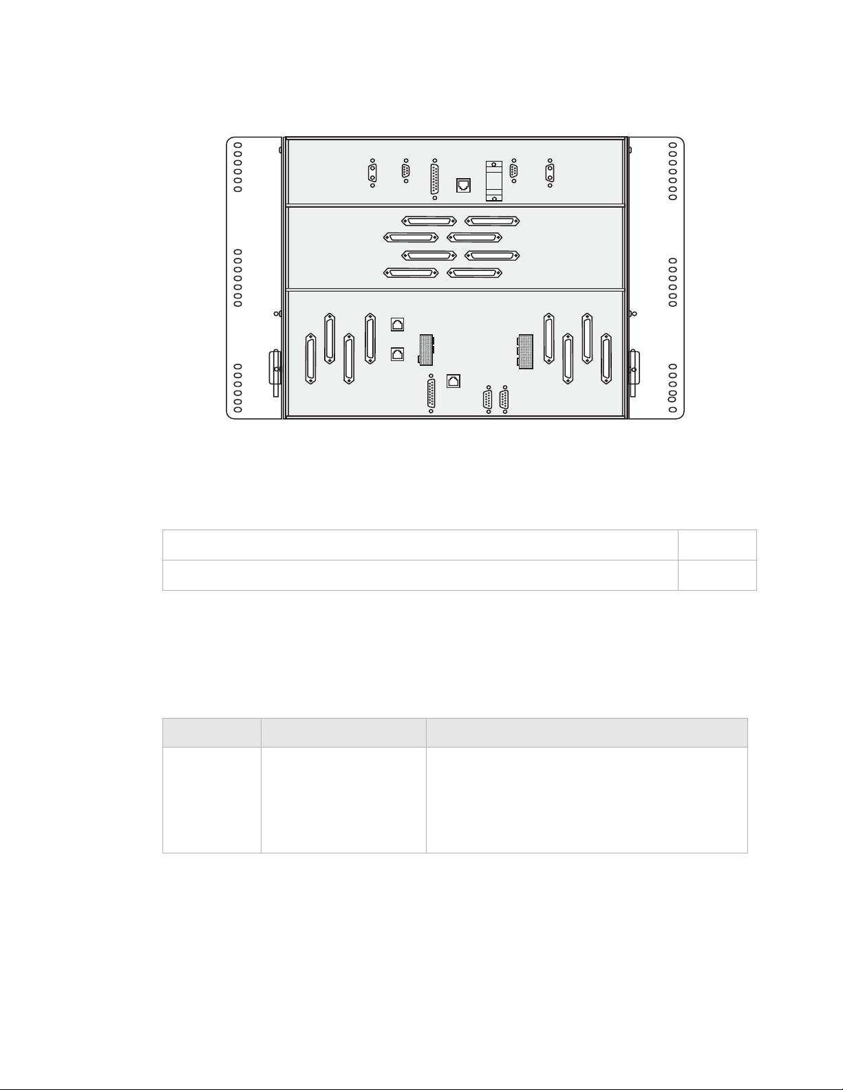
Note: The high capacity shelf does not require the installation of an additional fan
shelf since the fan unit is integral to the shelf itself. Check Figure 1-1, “Alcatel-Lucent
1665 DMX High-Capacity shelf backplane” (p. 1-2) to determine if the shelf is a
Alcatel-Lucent 1665 DMX High-Capacity shelf shelf. If the shelf you are installing is
NOT equipped with the additional middle connectors (J20 - J27), refer to the 1665
DMX Release 5.0 Installation Manual. Installation details for the 1665 DMX standard
shelf are not included in this issue.
............................................................................................................................................................................................................................................................
365-372-304R7.1
Issue 2 March 2008
I-1
Physical installation and powering
............................................................................................................................................................................................................................................................
Figure 1-1 Alcatel-Lucent 1665 DMX High-Capacity shelf backplane
Contents
-48VB
-48RTNB
J23DIN
J27 D OUT
J7
DIN
J8
D OUTJ6C OUT
P15
J22CIN
J26 C OUT
INTEROP
J5
CIN
J14
SYNC2
J19
J16
IAOLAN
CTL
J10
X.25
EXP2
J11
MISC
IN
OUT
DLAN
J17
MODEM
J18
J12
ALM
J15
FAN
OUT
CTL
This section is organized into the following chapters:
J9
SYNC1
J20 A IN
J21BIN
J24 A OUT
J25 B OUT
EXP1
IN
J13
ALM MULT
P14
-48VA
-48RTNA
J4
BINJ2AIN
J3
B OUTJ1A OUT
-
-
Equipment and cable installation
Powering and initial circuit pack installation
Tools, test equipment, and accessories
This section lists the tools, test equipment and accessories needed to perform all the
procedures in this installation manual.
Listed below are the required tools, test equipment and accessories.
Quantity Description Comments
Screwdriver(s) A screwdriver(s) with the appropriate head(s) is
Chapter 1
Chapter 2
(are) required for securing the mounting screws,
repositioning the mounting brackets, installing the
interfacing cables, and for setting the circuit
breakers to the OFF position.
............................................................................................................................................................................................................................................................
I-2
365-372-304R7.1
Issue 2 March 2008

Physical installation and powering
............................................................................................................................................................................................................................................................
Quantity Description Comments
1 Thomas & Betts* R-
5648B Crimping Tool
†
1 Paladin
Coaxial Wire
Stripper R-5648B
Replacement Paladin
Cassette R-5648B D5
1 Wire-Wrap Gun
R-4496A
1 Impact Tool -Wire
R-5974
1 ESD Wrist Strap
R-4987C
1 Torque Wrench
R-5952
The crimping tool and wire stripper are only
required if installing DS3 cables. The replacement
cassette is for the wire stripper tool.
†
The wire-wrap gun is required for terminating
DS1 cable and must be able to accommodate 24
gauge wire.
The impact tool is required for terminating
Ethernet cable onto a 110 type panel.
A wrist strap must be worn when handling circuit
packs. Use the electrostatic discharge (ESD) jack
provided on the shelf.
A torque wrench (50-250 IN-LBS) is used when
tightening the
1665 DMX shelf to the frame. It is
also used when reattaching the mounting brackets
to the 1665 DMX shelf.
1 Multimeter (Optional)
ITE-6379C
The voltmeter must be capable of measuring DC
voltage in the 40 to 60 volt range. The use of the
voltmeter is optional since the shelf will alarm or
shut down if the proper voltage is not supplied.
1 Ohmmeter
ITE-6379C
1 DS1 Error Rate Test Set
ITE-7113
An ohmmeter is required to verify that the
1665
DMX is properly grounded.
A DS1 error rate test set is required for testing of
DS1 cabling. A T-BERD 2209 or equivalent is
recommended.
1 DS3 Error Rate Test Set
ITE-7113
A DS3 error rate test set is required for testing of
DS3 cabling. A T-BERD 209 or equivalent is
recommended.
1 SONET Optical Test Set An OC-3, OC-12 or OC-48 test set as required for
testing of optical circuit packs. An Agilent
OmniBER 718 or equivalent is recommended.
............................................................................................................................................................................................................................................................
365-372-304R7.1
Issue 2 March 2008
I-3

Physical installation and powering
............................................................................................................................................................................................................................................................
Quantity Description Comments
2 or 3 LC-Type Optical Fiber
Jumper ITE-7169
(108918269)
2 or 3 15-dB LC-Type LBO
ITE-7196 (108279480)
2 20-dB LC-Type LBO
ITE-7196 (108279530)
2 LC-Type Optical Fiber
Jumper (108918269)
Two optical fiber jumpers with LC type
connectors are required to optically loop the 1665
DMX shelf for test purposes. In addition, for
shelves containing optical circuit packs in any of
the Function unit slots, a single optical fiber
jumper is required for testing of the individual
ports.
Two 15-dB LBOs are required when optically
looping the 1665 DMX shelf for test purposes. In
addition, for shelves containing optical circuit
packs in any of the Function unit slots, a single
15-dB LBO is required for testing of the
individual ports
Two 20-dB LBOs are required when optically
looping the 1665 DMX shelf equipped with
LNW60.
Two optical fiber jumpers with LC type
connectors are required to optically loop the 1665
DMX shelf for test purposes.
Noyes OFS 300-200X
Optical Fiber Scope
ITE-7129
2.5 mm Universal
Adapter Cap ITE-7129
D1
1.25mm Universal
Adapter Cap ITE-7129
D2
Noyes VFS-1 ITE-7187
Video Fiber Scope
Individual Presaturated
Alcohol Wipes ITE7136
1 CLETOP Cleaning
Cassette ITE-7137
Optical Fiber Scope
For use with the Noyes OFS 300-200X Optical
Fiber Scope
This equipment may not be necessary at all
1
locations. It is to be used when the ports need to
be verified for cleanliness. If care is exercised
when cleaning fibers, the video scope may not be
needed
99% pure isopropyl alcohol
Type A Reel
............................................................................................................................................................................................................................................................
I-4
365-372-304R7.1
Issue 2 March 2008

Physical installation and powering
............................................................................................................................................................................................................................................................
Quantity Description Comments
1 CLETOP Cleaning
Cassette Replacement
Reel
ITE-7137 D1
Luminex Stick Port
Cleaners ITE-7134 &
ITE-7135
Luminex Cloth R-6033 5.5” x 5.5”
* Registered trademark of Thomas & Betts Corporation
† Registered trademark of Paladin Corporation.
PC and cable requirements for WaveStar® CIT
This section lists the required equipment needed to run the WaveStar® CIT software with
the 1665 DMX.
Quantity Description Comments
1 Personal Computer
(PC)
1 CIT Interface Cable 8-ft. long RJ45 to 9-pin D-sub
Type A Reel
1.25 mm and 2.5 mm sizes
See PC minimum requirements
below.
serial cable (Comcode
848748869).
1 Cross Over LAN
Cable (If CIT cable is
10-ft. long cable (Comcode
109321810) or equivalent.
not available)
............................................................................................................................................................................................................................................................
365-372-304R7.1
Issue 2 March 2008
I-5

Physical installation and powering
............................................................................................................................................................................................................................................................
PC minimum requirements
It is anticipated that most customers will dedicate a laptop or personal computer (PC) to
run the WaveStar® CIT software. However, any properly configured computer will also
suffice. The following table shows the requirements for the computer:
Note: Windows Vista is not supported
............................................................................................................................................................................................................................................................
I-6
365-372-304R7.1
Issue 2 March 2008

Physical installation and powering
............................................................................................................................................................................................................................................................
Table 1-1 Computer requirements
Components Minimum
*
Recommended
Processor Pentium 266 MHz Pentium III 500 MHz
RAM (1 system
128 MB 256 MB
view)
RAM (up to 5
256 MB 256 MB
system views)
Virtual Memory 139 MB 267 MB
Available Hard
Disk Space
†
Video 800X600 256 Colors
Network Interface 10/100 baseT Network
500 MB 600 MB
1024X768 16 Million
(8 Bit)
Colors (24 Bit)
10/100 baseT Network
Card
Card
CD ROM Drive Required Required
Operating System Windows
Windows
Windows
®
NT 4.0,
®
2000 or
®
XP
Windows
Windows
Windows
®
NT 4.0,
®
2000 or
®
XP
Internet Browser Internet Explorer
5.0/5.5/6.0
Network Interface
Card (NIC)
Drivers
Latest NIC Divers
installed from
Manufacturers web site
Video Drivers Latest Video Divers
installed from
Manufacturers web site
* Minimum requirements are sufficient to run two to three GUI System Views, unless
otherwise noted. Recommended requirements are intended to be used as a general
guideline to optimize WaveStar
connections and multiple NE types, the processor type and speed and the memory size will
all factor into CIT performance.
† Available hard disk space required to install and store the CIT and Generic Software is
approximately 250 MB (it is 550 MB, if all graphical packages are installed). The additional
disk space specified is to provide hard disk space to store Alcatel-Lucent 1665 DMXbackup
files.
®
CIT performance. As the CIT is used with multiple NE
Internet Explorer
5.0/5.5/6.0
Latest NIC Divers
installed from
Manufacturers web site
Latest Video Divers
installed from
Manufacturers web site
............................................................................................................................................................................................................................................................
365-372-304R7.1
Issue 2 March 2008
I-7

Physical installation and powering
............................................................................................................................................................................................................................................................
............................................................................................................................................................................................................................................................
I-8
365-372-304R7.1
Issue 2 March 2008

1 Equipment and cable
installation
Overview
Purpose
This section provides installation and cabling instructions for the Alcatel-Lucent 1665
Data Multiplexer (Alcatel-Lucent 1665 DMX).
Contents
This chapter provides information on the following topics:
Planning 1-3
Connector references 1-7
Inspection 1-8
Alcatel-Lucent 1665 DMX High-Capacity shelf installation 1-9
Heat baffle installation 1-14
Power cable and cable bracket installation 1-16
Fiber management installation (optional) 1-27
Installing the fiber ducts (optional) 1-31
Cable and optical fiber installation 1-32
DS1 cable installation 1-34
DS3/EC1 and TMUX 48-port cable installation 1-41
12-DS3/EC1 and TMUX (LNW16 LNW18) cable installation 1-52
10/100BaseT backplane Ethernet cable installation 1-58
Ethernet cabling to SFP modules on circuit pack faceplates 1-62
IAO LAN and TCP/IP cable installation 1-64
Modem cable installation 1-69
............................................................................................................................................................................................................................................................
365-372-304R7.1
Issue 2 March 2008
1-1

Equipment and cable installation
............................................................................................................................................................................................................................................................
Sync cable installation 1-71
Office alarm cable installation 1-77
Miscellaneous (environmental) discrete telemetry cable installation 1-83
Main optical fiber installation (OC-12, OC-48, OC-192) 1-87
Fiber installation for low-speed packs 1-89
1000Base-F and 100Base-F fiber installation 1-91
Fibre channel fiber installation 1-93
CIT cable installation 1-95
Final operations 1-98
............................................................................................................................................................................................................................................................
1-2
365-372-304R7.1
Issue 2 March 2008
Loading...