


 Loading...
SAVE THESE IMPORTANT SAFETY
INSTRUCTIONS!
1.Read and understand all instructions.
2.Follow all warnings and instructions marked on the product.
3.Unplug this product from the wall outlet before cleaning. Do not use liquid cleaners or aerosol cleaners. Use a damp cloth for cleaning.
4.Do not use this product near water; for example, near a bath tub, wash bowl, kitchen sink, or laundry tub, in a wet basement, or near a swimming pool.
5.This product should be operated only from the type of power source indicated on the marking label. If you are not sure of the type of power supply to your home, consult your dealer or local power company.
6.Do not allow anything to rest on the power cord. Do not locate this product where the cord will be abused by persons walking on it.
7.Do not overload wall outlets and extension cords, as this can result in the risk of fire or electric shock.
8.To reduce the risk of electric shock, do not disassemble this product, but take it to a qualified serviceman when service or repair work is required. Opening or removing covers may expose you to dangerous voltages or other risks. Incorrect reassembly can cause electric shock when the appliance is subsequently used.
9.Unplug this product from the wall outlet and refer servicing to qualified service personnel under the following conditions:
∙When the power supply cord or plug is damaged or frayed;
∙If liquid has been spilled into the product;
∙If the product has been exposed to rain or water;
∙If the product does not operate normally by following the operating instructions. Adjust only those controls that are covered by the operating instructions; improper adjustment of other controls may result in damage and will often require extensive work by a qualified technician to restore the product to normal operation;
∙If the product has been dropped or the housing has been damaged;
∙If the product exhibits a distinct change in performance.
10.Avoid using a telephone (other than a cordless type) during an electrical storm. There may be a remote risk of electric shock from lightning.
11.Do not use the telephone to report a gas leak in the vicinity of the leak.
Contents
Note:
When using hyperlinks to navigate through this document, you may use either the "back" button of your reader software to return to the table of contents, or the bookmark, using the bookmark display button.
SECTION 1: QUICK START PROCEDURES
GETTING STARTED
Delivery Check
Placement of ADSL High Speed Modem
Wall-Mounting Option
Filter Installation
Determining Your Service Type
BRIDGED SERVICE
System Requirements
Hardware Installation
Accessing Online Services
POINT TO POINT SERVICE
System Requirements
Hardware Installation
Accessing Online Services
Windows 95/Windows 98 Dial-Up Procedures
Windows NT Dial-Up Procedures
ATM-25 SERVICE
System Requirements
Hardware Installation
Accessing Online Services
SECTION 2: DESCRIPTION OF FEATURES
MODEM CONNECTIONS
Connector Pinout
Power Supply
Visual Indicators
Subscriber Line Interface
Ethernet Interface
Single PC Configuration
Straight-Through Cable Layout
Multiple PC Configuration
Crossover Cable Layout
ATMF-25 Interface
NETWORK CONNECTIONS
Virtual Connections
ATM-Forum Interface
Ethernet Interface
ISP/Corporate Network Requirements
BRIDGED CONNECTIONS
Multiprotocol
Number of Machines Supported
Plug and Play
PC/Workstation Configuration
Bridged Service with Filtering
POINT TO POINT TUNNELING CONNECTIONS
Introduction
PPP/PPTP Network
Establishing PPP/PPTP Connections
Number of PPP/PPTP Connections Supported
LAN Protocols Supported
Known Limitations
ADVANCED CONFIGURATIONS
Overview
IP Parameters
Sample Configurations
Ping-of-Life Procedure
Ping-to-Defaults Procedure
CHANGING THE MODEM SETTINGS
Configuring the Browser
Accessing the ADSL Modem Interface
Welcome Page
Basic Configuration
Advanced Configuration
Bridge Configuration
Basic PPP/PPTP Configuration
Advanced PPP/PPTP Configuration
System Overview Page
REGULATORY INFORMATION
Environmental Conditions
Safety Standards
Power Supply
Conformance Declarations
Interference Information Part 15 of FCC Rules For Canadian Modem Users
Pour les Utilisateurs Canadiens de Modem TROUBLESHOOTING TIPS
SECTION 1: QUICK START PROCEDURES
This section of the 1000 ADSL High Speed Modem User’s Guide provides the basic instructions to install your modem and access online services as quickly as possible. Procedures include steps for correct placement of your modem, cable connections, and switching on the modem. These quick start procedures assume a single PC configuration using the modem's default settings.
A detailed description of features is provided in section 2 of this user's guide. Section 2 also provides a description of advanced configurations used in small office environments. Because the Alcatel high speed modem provides a user interface to your PC, you can change default settings of the modem to accommodate specific networking requirements.
GETTING STARTED
Delivery Check
Verify that the Alcatel 1000 High Speed Modem box contains all the components listed below:
∙ADSL high speed modem,
∙Power supply adapter with connecting cable,
∙Alcatel Data Cable (Category 5)
∙Wall-mounting template,
∙Two wall plugs and two screws for wall-mounting option, and
∙This user’s guide.
Placement of ADSL High Speed Modem
The ADSL high speed modem may be placed on an even, hard surface, such as a desk, or mounted on a wall. In either case, make sure the modem is near a power outlet, phone jack, and the PC to facilitate connections to these devices.

Wall-Mounting Option
Part of the packaging is a wall-mounting template. If you want to mount the modem on a wall, cut the template out and use it as follows (see figure 1).
1. Use template to mark positions of holes as indicated in table A.
|
Table A. |
|
|
|
|
If you mount the |
|
Mark positions of holes |
modem on... |
|
|
|
|
|
 Left side of corner
Right side of corner
Area of wall away from corner

 A1 and A2

 B1 and B2
Either A1 and A2 or B1 and B2
2.Drill the marked holes with a 6-mm (0.24-in.) diameter drill bit to a minimum depth of 35 mm (1.38 in.).
3.Insert the wall plugs in the drilled holes.
4.Insert the screws in the wall plugs and tighten them, leaving at least 3 mm (0.12 in.) protruding.
5.Position the modem over the upper screw (A1 or B1) and pull the box down until you hear a click.
6.Rotate the modem toward the lower screw (A2 or B2) and push it until you hear a click.
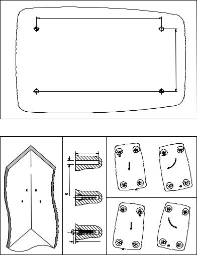
Template |
Corner |
Figure 1. Wall-Mounting Instructions
Filter Installation
To maintain normal phone service, a special filter must be installed in the Network Interface Device or NID, the gray box mounted on the outside of your home that terminates your phone connection. This filter, sometimes called a splitter, splits the voice (phone) signal from the ADSL (data) signal.
Set-up and installation charges for ADSL service typically include the filter installation. If you are not sure that the filter is installed, contact your service provider.

Determining Your Service Type
Note:
Before continuing, you must know the type of service you are being provided. If you do not know your service type, contact your service provider for this information. Your service type is one of the following:
∙Bridged Service (RFC 1483) [with or without filtering]
∙Point To Point Service (PPP)
∙ATM-25 Service (ATMF)
The ADSL modem is available in various models. The model must support the type of service you are being provided. Table B lists the model numbers and the types of service supported. The model number is on the bottom of the modem.
Table B.
Service Type |
Model Number |
|
|
ATM-25 Service (ATMF) |
3EC 18200 AB |
|
|
Bridged Service (RFC 1483) |
3EC 18202 AB |
|
|
Bridged Service (RFC 1483) |
3EC 18202 BB |
Point To Point Service (PPP) |
|
|
|
Bridged Service (RFC 1483) with |
3EC 18202 DB |
Filtering |
|
Point To Point Service (PPP) |
|
|
|
|
|
BRIDGED SERVICE
If your service provider is providing bridged service, your ADSL modem should have model number 3EC 18202 AB, 3EC 18202 BB, or 3EC 18202 DB on the bottom of the modem case.
System Requirements
The Alcatel 1000 ADSL high speed modem requires a PC or workstation equipped with an Ethernet 10Base-T network adapter card.
Note:
Before you begin, you will need to ask your service provider whether your connection will use static addressing, or DHCP (dynamic) addressing. You will need this information at step 9.
Hardware Installation
To connect your high speed ADSL modem, follow these steps:
1.Make sure the modem on/off switch is set to the O (off) position.
2.Connect the jack end of the power cable to the modem power socket.
3.Plug the other end of the power cable (the end with the power supply adapter) to an electrical outlet.
4.Connect one end of a standard telephone cable (not provided) to the modem connector labeled LINE.
Note:
The line cable may be provided by your service provider during installation, or it can be purchased at your local electronics supply store.
5.Connect the other end of the line cable to a phone jack.
6.Connect one end of the Alcatel Data Cable (provided) to the modem connector labeled 10BASE-T.
7.Connect the other end of the Alcatel Data Cable to the Ethernet 10Base-T network adapter card in your PC.
8.Start your PC.
9.Click Start, Settings, Control Panel, and finally, the Network icon.
10.Click the Configuration tab.
11.Scroll down to the TCP/IP protocol adapters, find the adapter which includes the name of your Ethernet card, and select it.
12.Click the Properties button.
13.When the TCP/IP Properties window appears, click the IP Address tab.
14.If your service is DHCP, click the Obtain an IP address automatically radio button. If your service uses static addressing, press the Enter IP address radio button, and enter the IP address and subnet mask assigned to you by your service provider.
15.Restart your computer.
16.Turn on the modem by switching the on/off switch to |.
Power/Sync Light
The Power/Sync light begins blinking. After about two minutes, the light should be solid green. If the light is not solid green, check the telephone line cable between the modem LINE connector and the phone jack. If this connection is secure and the Power/Sync light is not solid green, contact your service provider for assistance.
10BASE-T Light
The 10BASE-T light should be solid green. If the light is not solid green, check the Alcatel Data Cable connection between the modem 10BASE-T connector and the Ethernet 10Base-T network adapter card in your PC. If this connection is secure and the 10BASE-T light is not solid green, contact your service provider for assistance.
Accessing Online Services
When your PC is started and your ADSL modem is switched on, a connection is automatically established with your online service. Through this connection, you can access the World Wide Web or your corporate network or other online services.
Network Address Assignments
Network addresses are either manually assigned (static addresses) or dynamically assigned. If the address is fixed, your PC must be configured with an IP address provided by your service provider. If the address is dynamic, your PC must be configured to use dynamic host configuration protocol (DHCP).
If you are not sure which network addressing method you are using, ask your service provider for this information.
POINT TO POINT SERVICE
If your service provider is providing point to point (PPP) service, your ADSL modem should have model number 3EC 18202 BB or 3EC 18202 DB on the bottom of the modem case.
System Requirements
The Alcatel 1000 ADSL high speed modem requires a PC or workstation equipped with the following:
1.Ethernet 10Base-T network adapter card,
2.Operating system such as Windows 95, Windows 98, or Windows NT (see note)
3.Microsoft Virtual Private network (VPN) Adapter
Note:
If you have an operating system other than Windows 95, Windows 98, or Windows NT, contact your service provider for additional system requirements.
PPP service requires a user account to the service provider of your choice.
Hardware Installation
To connect your high speed ADSL modem, follow these steps:
1.Make sure the modem on/off switch is set to the O (off) position.
2.Connect the jack end of the power cable to the modem power socket.
3.Plug the other end of the power cable (the end with the power supply adapter) to an electrical outlet.
4.Connect one end of a standard telephone cable (not provided) to the modem connector labeled LINE.
Note:
The line cable may be provided by your service provider during installation, or it can be purchased at your local electronics supply store.
5.Connect the other end of the line cable to a phone jack.
6.Connect one end of the Alcatel Data Cable (provided) to the modem connector labeled 10BASE-T.
7.Connect the other end of the Alcatel Data Cable to the Ethernet 10Base-T network adapter card in your PC.
8.Start your PC.
9.Click Start, Settings, Control Panel, and finally, the Network icon.
10.Click the Configuration tab.
11.Scroll down to the TCP/IP protocol adapters, find the adapter which includes the name of your Ethernet card, and select it.
12.Click the Properties button.
13.When the TCP/IP Properties window appears, click the IP Address tab.
14.Press the Specify IP address radio button, and enter the IP address and subnet mask assigned to you by your service provider.
15.Restart your PC.
16.Turn on the modem by switching the on/off switch to |.
Power/Sync Light
The Power/Sync light begins blinking. After about two minutes, the light should be solid green. If the light is not solid green, check the telephone line cable between the modem LINE connector and the phone jack. If this connection is secure and the Power/Sync light is not solid green, contact your service provider for assistance.
10BASE-T Light
The 10BASE-T light should be solid green. If the light is not solid green, check the Alcatel Data Cable connection between the modem 10BASE-T connector and the Ethernet 10Base-T network adapter card in your PC. If this connection is secure and the 10BASE-T light is not solid green, contact your service provider for assistance.
Accessing Online Services
To access online services, you must dial-up your service provider. The procedure to use depends on the operating system of your PC. Procedures are provided for Windows 95, Windows 98, and Windows NT.
Windows 95/Windows 98 Dial-Up Procedures
The dial-up feature is not included in the Windows 95 operating system. It can be downloaded without cost from the Microsoft web site http://www.microsoft.com or obtained through other software distribution sources. Procedures for downloading and installing this software are provided next.
Downloading Dial-Up Networking Software Upgrade (Windows 95 Only)
To download the Windows Dial-Up Networking 1.3 Performance and Security Upgrade for Windows 95:
1.Access the Microsoft website at http://www.microsoft.com.
2.In the Contents frame, select Free Downloads.
3.Scroll to Support Drivers, Patches and Service Packs and select Windows95 Updates. The Microsoft Windows95 Downloads page appears.
4.Select Windows 95 in the Select a product or feature box.
5.Select Networking & Communications in the Select a category box.
6.Click Go. The Windows Dial-Up Networking 1.3 Performance and Security Upgrade for Windows 95 is listed.
7.Click this hyperlink to access the Windows Dial-Up Networking 1.3 Performance and Security Upgrade for Windows 95 page.
8.Click the Download Now hyperlink in the upper right corner of the page. The MSDUN1.3 download page appears.
9.Click the link to a site near you. The program prompts you for a directory to download the msdun13.exe file.
10.Specify a directory. The msdun13.exe file is downloaded to this directory.
Installing Dial-Up Networking Software (Windows 95 Only)
The Dial-Up Networking 1.3 Performance & Security Upgrade (MSDUN13.exe) must be installed to setup a dial-up connection to your corporate headquarters or your ISP.
Note:
During the installation, you will be asked to restart your workstation. Make sure you save your work and exit from all applications (except Internet Explorer) before beginning the installation.
Note:
If you installed Windows 95 from a CD, have the Windows 95 CD ready before you begin the installation.
To install the MSDUN13.exe file, proceed as follows:
1.At your desktop, click Start, and select Run from the menu. The Run window appears.
2.Specify the path for the MSDUN13.exe file in the Open box and click OK.
This will install Microsoft Dial-Up Networking 1.3 for Windows 95. Do you wish to continue?
3.Click Yes. The End-User License Agreement window appears. This license agreement must be accepted to start the installation.
4.Click Yes.
During the installation, you will be prompted to restart the workstation twice. After restarting, the installer will rebuild your driver twice, once for Dial-Up- Networking and once to enable virtual private networking. This is normal.
Note:
Setup may notify you of a version conflict and ask if you want to keep an original newer file. If this happens, click Yes (always save the newer file).
When the installation is complete, the Microsoft VPN Adapter is added to the list of devices in the Make New Connection window.
Installing Dial-Up Networking Software (Windows 98 Only)
To check whether VPN is installed:
1.Select Start, Settings, Control Panel, Network.
2.Select the Configuration tab. On the Configuration list, there should be a listing for Microsoft Virtual Private Networking Adapter. If not, select Add and double-click Adapter.
3.Scroll down the Manufacturers list and select Microsoft.
4.Under Network Adapters, double-click Microsoft Virtual Private Networking (VPN support) Adapter.

Note:
If you do not see the VPN adapter on the list, it means that the operating system component file for this adapter was not loaded when Windows 98 was installed on your PC. You will need your Windows 98 CD-ROM at this point. The procedure follows:
5.Select Start, Settings, click Control Panel.
6.Double-click the Add/Remove Programs icon. The Add/Remove Programs Properties window (shown below) opens.
7.Click the Windows Setup tab. Momentarily, the Searching for Installed Components window pops up, then disappears.
8.Click on Communications in the Components: list.
9.Press the Details… button.
10.Scroll down the subcomponents list until you see Virtual Private Networking. The box next to this listing needs to have a check mark in it. If it does not, click it to install it.
11.Click OK, and then OK in the Add/Remove Programs Properties window.
12.Your PC will prompt you to insert your Windows 98 CD. When you do this, VPN will install, and you can follow the steps under Installing Dial-Up Networking Software (Windows 98 Only) to activate VPN.
Configure the Connection
To configure a new PPP connection to your corporate network or an ISP, do the following:
1.Double-click the My Computer icon.
2.Double-click the Dial-Up Networking icon.
3.Activate the Make New Connection application by double-clicking on the corresponding icon. The Welcome to Dial-Up Networking window appears (this window only appears the first time you use the Make New Connection application).
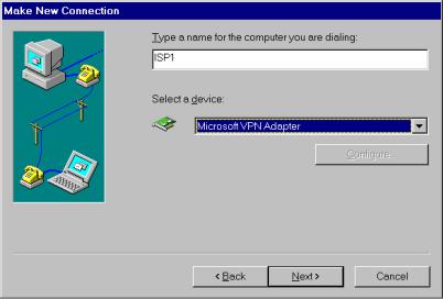
4.Click Next. The Make New Connection window appears (see figure 2).
Figure 2. Make New Connection (Windows 95 Example)
5.Enter a name for the ISP or corporate network you are dialing (this name appears with the icon that is created).
6.To create a connection to your ISP or corporate network, select Microsoft VPN Adapter in the Select a device box.
7.Click Next. The VPN Server field appears (see figure 3).
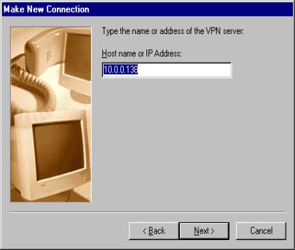
Figure 3. VPN Server Field (Windows 98 example)
8.Enter 10.0.0.138 (default IP address of the ADSL modem).
9.Click Next. A window appears indicating you have successfully installed a new dial-up networking Connection.
10.Click Finish.
A new icon with the name of the connection you just created is added to your Dial-Up Networking folder (see figure 4). You can use this icon to make a connection to your corporate network or ISP.
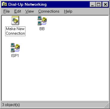
Figure 4. Dial-Up Networking Folder (Windows 95 Example)
Make the Connection
After configuring the PPP connection, make the connection:
1.Double-click the My Computer icon.
2.Double-click the Dial-Up Networking icon.
3.Activate the connection setup by double-clicking the icon of the connection you want to establish. The Connect To window appears (see figure 5).
Figure 5. Connect To (Windows 98 Example)
4.Enter the User name and Password (the IP address defaults to the modem's IP address of 10.0.0.138).
5.Click Connect. The Connecting To window appears (see figure 6).
Figure 6. Connecting To (Windows 95 Example)
This window indicates the status of the connection process. When the connection is established, a connection icon appears on your desktop. You are now connected to the destination specified in the connection icon.
Note:
User name and password are unique for a specific remote destination. They must be entered each time you want to set up a connection. Therefore it is useful to create multiple icons, one to each remote destination.
If you intend to use this connection often, it may be useful to create a shortcut to it on your desktop.
To create a shortcut, select the icon and drag it to your desktop. The program asks if you want to create a shortcut to the selected item. Select Yes and a copy of the selected icon appears on your desktop.
You can now make a PPP connection by double-clicking the shortcut.
Break the Connection
To break the connection, proceed as follows:
1.Click the connection icon.
2.Click Disconnect. The network connection to your ISP or corporate network is disconnected.
Windows NT Dial-Up Procedures
Add Point To Point Tunneling Protocol
Before making connections, the PPTP Network Protocol must be added to your Windows NT platform.
To install the PPTP networking protocol, proceed as follows:
1.Double-click the My Computer icon.
2.Double-click the Control Panel icon.
3.Double-click the Network icon. The Network Window appears (see figure 7)
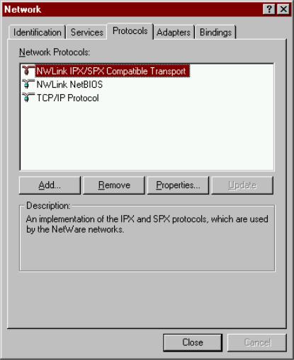
Figure 7. Network Window
4.Select the Protocols tab and click Add. The Select Network Protocol
Window appears (see figure 8).
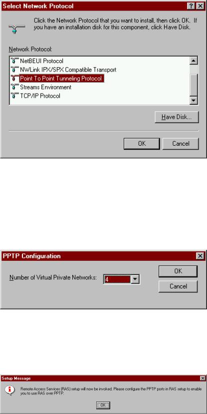
Figure 8. Select Network Protocol Window
5.Scroll the dialog box and select Point-to-Point Tunneling Protocol from the list.
6.Click OK. The system prompts for a directory to copy installation files.
7.Specify the directory and click Continue. The installer loads the PPTP files. The PPTP Configuration window appears (see figure 9).
Figure 9. PPTP Configuration Window
8.Click the scroll arrow to select the maximum number of concurrent remote PPTP connections to this Remote Access Services (RAS) server.
9.Click OK to continue. The Setup Message Window appears (see figure 10).
Figure 10. Setup Message Window
Loading...