


WL-5470AP
802.11g Hi Power
Multifunction AP/Router
User’s Manual

Declaration of Conformity
We, Manufacturer/Importer
OvisLink Corp.
5F., NO.6, Lane 130, Min-Chuan Rd.,
Hsin-Tien City, Taipei County, Taiwan
Declare that the product
802.11b/g Multi-function Wireless Access Point
AirLive WL-5470AP is in conformity with
In accordance with 89/336 EEC-EMC Directive and 1999/5 EC-R & TTE Directive
Clause |
Description |
■ EN 300 328 V1.7.1 Electromagnetic compatibility and Radio spectrum Matters (ERM);
(2006-10) Wideband transmission equipment operating in the 2.4GHz ISM band
And using spread spectrum modulation techniques; Part 1 technical Characteristics and test conditions Part2 Harmonized EN covering
Essential requirements under article 3.2 of the R&TTE Directive
■ EN 301 489-1 V1.5.1 |
Electromagnetic compatibility and Radio spectrum Matters (ERM); |
(2004-11) |
Electromagnetic compatibility(EMC) standard for radio equipment and |
■ EN 301 489-17 V1.2.1 |
Services; Part 17 Specific conditions for wideband data and |
(2002-08) |
HIPERLAN equipment |
■ EN 50371:2002 |
Generic standard to demonstrate the compliance of low power |
|
Electronic and electrical apparatus with the basic restrictions related |
|
to human exposure to electromagnetic field (10MHz – 300GHz) |
|
-General public |
■ EN 60950-1:2001/ |
Safety for information technology equipment including electrical |
A11:2004 |
business equipment |
■ CE marking |
|
Manufacturer/Importer
Signature |
|
|
||
Name |
|
Albert Yeh |
Date 2007/6/28 |
|
Position/ Title |
: |
|
Vice President |
|
(Stamp)

AirLive WL-5470AP CE Declaration Statement
Country |
Declaration |
Country |
Declaration |
cs |
OvisLink Corp. tímto prohlašuje, že tento AirLive |
lt |
Šiuo OvisLink Corp. deklaruoja, kad šis AirLive WL- |
Česky [Czech] |
WL-5470AP je ve shodě se základními |
Lietuvių |
5470AP atitinka esminius reikalavimus ir kitas |
|
požadavky a dalšími příslušnými ustanoveními |
[Lithuanian] |
1999/5/EB Direktyvos nuostatas. |
|
směrnice 1999/5/ES. |
|
|
da |
Undertegnede OvisLink Corp. erklærer herved, |
nl |
Hierbij verklaart OvisLink Corp. dat het toestel AirLive |
Dansk [Danish] |
at følgende udstyr AirLive WL-5470AP |
Nederlands [Dutch |
WL-5470AP in overeenstemming is met de |
|
overholder de væsentlige krav og øvrige |
|
essentiële eisen en de andere relevante bepalingen |
|
relevante krav i direktiv 1999/5/EF. |
|
van richtlijn 1999/5/EG. |
de |
Hiermit erklärt OvisLink Corp., dass sich das |
mt |
Hawnhekk, OvisLink Corp, jiddikjara li dan AirLive |
Deutsch |
Gerät AirLive WL-5470AP in Übereinstimmung |
Malti [Maltese] |
WL-5470AP jikkonforma mal-ħtiġijiet essenzjali u ma |
[German] |
mit den grundlegenden Anforderungen und den |
|
provvedimenti oħrajn relevanti li hemm fid-Dirrettiva |
|
übrigen einschlägigen Bestimmungen der |
|
1999/5/EC. |
|
Richtlinie 1999/5/EG befindet. |
|
|
et |
Käesolevaga kinnitab OvisLink Corp. seadme |
hu |
Az OvisLink Corporation kijelenti, hogy az AirLive |
Eesti [Estonian] |
AirLive WL-5470AP vastavust direktiivi |
Magyar |
WL-5470AP megfelel az 1999/05/CE irányelv |
|
1999/5/EÜ põhinõuetele ja nimetatud direktiivist |
[Hungarian] |
alapvető követelményeinek és egyéb vonatkozó |
|
tulenevatele teistele asjakohastele sätetele. |
|
rendelkezéseinek. |
en |
Hereby, OvisLink Corp., declares that this AirLive |
pl |
Niniejszym OvisLink Corp oświadcza, że AirLive WL- |
English |
WL-5470AP is in compliance with the essential |
Polski [Polish] |
5470AP jest zgodny z zasadniczymi wymogami oraz |
|
requirements and other relevant provisions of |
|
pozostałymi stosownymi postanowieniami Dyrektywy |
|
Directive 1999/5/EC. |
|
1999/5/EC. |
es |
Por medio de la presente OvisLink Corp. declara |
pt |
OvisLink Corp declara que este AirLive WL-5470AP |
Español |
que el AirLive WL-5470AP cumple con los |
Português |
está conforme com os requisitos essenciais e outras |
[Spanish] |
requisitos esenciales y cualesquiera otras |
[Portuguese] |
disposições da Directiva 1999/5/CE. |
|
disposiciones aplicables o exigibles de la |
|
|
|
Directiva 1999/5/CE. |
|
|
el |
ΜΕ ΤΗΝ ΠΑΡΟΥΣΑ OvisLink Corp. ΔΗΛΩΝΕΙ |
sl |
OvisLink Corp izjavlja, da je ta AirLive WL-5470AP v |
Ελληνική [Greek] |
ΟΤΙ AirLive WL-5470AP ΣΥΜΜΟΡΦΩΝΕΤΑΙ |
Slovensko |
skladu z bistvenimi zahtevami in ostalimi relevantnimi |
|
ΠΡΟΣ ΤΙΣ ΟΥΣΙΩΔΕΙΣ ΑΠΑΙΤΗΣΕΙΣ ΚΑΙ ΤΙΣ |
[Slovenian] |
določili direktive 1999/5/ES. |
|
ΛΟΙΠΕΣ ΣΧΕΤΙΚΕΣ ΔΙΑΤΑΞΕΙΣ ΤΗΣ ΟΔΗΓΙΑΣ |
|
|
|
1999/5/ΕΚ. |
|
|
fr |
Par la présente OvisLink Corp. déclare que |
sk |
OvisLink Corp týmto vyhlasuje, že AirLive WL- |
Français [French] |
l'appareil AirLive WL-5470AP est conforme aux |
Slovensky [Slovak] |
5470AP spĺňa základné požiadavky a všetky |
|
exigences essentielles et aux autres dispositions |
|
príslušné ustanovenia Smernice 1999/5/ES. |
|
pertinentes de la directive 1999/5/CE |
|
|
it |
Con la presente OvisLink Corp. dichiara che |
fi |
OvisLink Corp vakuuttaa täten että AirLive WL- |
Italiano [Italian] |
questo AirLive WL-5470AP è conforme ai |
Suomi [Finnish] |
5470AP tyyppinen laite on direktiivin 1999/5/EY |
|
requisiti essenziali ed alle altre disposizioni |
|
oleellisten vaatimusten ja sitä koskevien direktiivin |
|
pertinenti stabilite dalla direttiva 1999/5/CE. |
|
muiden ehtojen mukainen |
lv |
Ar šo OvisLink Corp. deklarē, ka AirLive WL- |
|
Hér með lýsir OvisLink Corp yfir því að AirLive WL- |
Latviski [Latvian] |
5470AP atbilst Direktīvas 1999/5/EK būtiskajām |
Íslenska [Icelandic] |
5470AP er í samræmi við grunnkröfur og aðrar kröfur, |
|
prasībām un citiem ar to saistītajiem |
|
sem gerðar eru í tilskipun 1999/5/EC. |
|
noteikumiem. |
|
|
sv |
Härmed intygar OvisLink Corp. att denna AirLive |
no |
OvisLink Corp erklærer herved at utstyret AirLive WL- |
Svenska |
WL-5470AP står I överensstämmelse med de |
Norsk [Norwegian] |
5470AP er i samsvar med de grunnleggende krav og |
[Swedish] |
väsentliga egenskapskrav och övriga relevanta |
|
øvrige relevante krav i direktiv 1999/5/EF. |
|
bestämmelser som framgår av direktiv |
|
|
|
1999/5/EG. |
|
|
A copy of the full CE report can be obtained from the following address:
OvisLink Corp. 5F, No.6 Lane 130,
Min-Chuan Rd, Hsin-Tien City, Taipei, Taiwan, R.O.C.
This equipment may be used in AT, BE, CY, CZ, DK, EE, FI, FR, DE, GR, HU, IE, IT, LV, LT, LU, MT, NL, PL, PT, SK, SI, ES, SE, GB, IS, LI, NO, CH, BG, RO, TR
FCC Certifications
This equipment has been tested and found to comply with the limits for a Class B digital device, pursuant to Part 15 of the FCC Rules. These limits are designed to provide reasonable protection against harmful interference in a residential installation. This equipment generates uses and can radiate radio frequency energy and, if not installed and used in accordance with the instructions, may cause harmful interference to radio communications. However, there is no guarantee that interference will not occur in a particular installation. If this equipment does cause harmful interference to radio or television reception, which can be determined by turning the equipment off and on, the user is encouraged to try to correct the interference by one or more of the following measures:
yReorient or relocate the receiving antenna.
yIncrease the separation between the equipment and receiver.
yConnect the equipment into an outlet on a circuit different from that to which the receiver is connected.
yConsult the dealer or an experienced radio/TV technician for help.
CAUTION:
Any changes or modifications not expressly approved by the grantee of this device could void the user’s authority to operate the equipment.
This device complies with Part 15 of the FCC rules. Operation is subject to the following two conditions: (1) This device may not cause harmful interference, and (2) This device must accept any interference received, including interference that may cause undesired operation.
FCC RF Radiation Exposure Statement
This equipment complies with FCC RF radiation exposure limits set forth for an uncontrolled environment. This equipment should be installed and operated with a minimum distance of 20cm between the radiator and your body.
CE Mark Warning
This is a Class B product. In a domestic environment, this product may cause radio interference, in which case the user may be required to take adequate measures.
All trademarks and brand names are the property of their respective proprietors.
Specifications are subject to change without prior notification.
AirLive WL_5470AP User’s Manual
2
Table of Contents |
|
Chapter I: Introduction ............................................................................................................... |
1 |
1.1 FEATURES................................................................................................................................. |
1 |
1.2 PARTS, NAMES, AND FUNCTIONS................................................................................................ |
2 |
1.3 FACTORY DEFAULT SETTINGS.................................................................................................... |
3 |
Chapter II: Hardware Connection .............................................................................................. |
4 |
2.1 CHECK THE LED:....................................................................................................................... |
4 |
Chapter III: About the Wireless Operation Modes ..................................................................... |
5 |
3.1 ACCESS POINT MODE ................................................................................................................ |
5 |
3.2 CLIENT MODE (INFRASTRUCTURE) ............................................................................................. |
6 |
3.3 CLIENT MODE (AD-HOC) ............................................................................................................ |
7 |
3.4 BRIDGE MODE ........................................................................................................................... |
8 |
3.5 WDS REPEATER MODE ............................................................................................................. |
9 |
3.6 UNIVERSAL REPEATER MODE .................................................................................................... |
9 |
3.7 WISP ( CLIENT ROUTER) MODE ............................................................................................... |
10 |
3.8 WISP + UNIVERSAL REPEATER MODE...................................................................................... |
11 |
3.9 GW MODE............................................................................................................................... |
11 |
Chapter IV: Configuration ........................................................................................................ |
13 |
4.1 MODE...................................................................................................................................... |
14 |
4.2 AP MODE SETTING .................................................................................................................. |
15 |
4.3 CLIENT MODE SETTING............................................................................................................ |
24 |
4.4 BRIDGE MODE SETTING ........................................................................................................... |
26 |
4.5 WDS REPEATER MODE SETTING ............................................................................................. |
28 |
4.6 UNIVERSAL REPEATER MODE SETTING .................................................................................... |
30 |
4.7 WISP (CLIENT ROUTER) MODE SETTING.................................................................................. |
31 |
4.8 WISP + UNIVERSAL REPEATER MODE SETTING........................................................................ |
34 |
4.9 GW MODE SETTING................................................................................................................. |
36 |
4.10 STATUS ................................................................................................................................. |
38 |
4.11 TCP/IP ................................................................................................................................. |
41 |
4.12 REBOOT ................................................................................................................................ |
42 |
Chapter V: Other...................................................................................................................... |
43 |
AirLive WL_5470AP User’s Manual
3
Chapter I: Introduction
WL-5470AP is world's most popular multi-function access point. It features an impressive total of 8 wireless multi-function modes that are not available in normal access point. In addition, the ACK timeout and RSSI feature makes it suitable for long distance application. From ordinary AP application to Hotspot and WISP usage, you will find the WL-5470AP is the device you want.
WL-5470AP is an IEEE802.11b/g compliant 11 Mbps & 54 Mbps Ethernet Wireless Access Point. The Wireless Access Point is equipped with two 10/100 M Auto-sensing Ethernet ports for connecting to LAN and also for cascading to next Wireless Access Point.
WL-5470AP provides 64/128bit WEP encryption, WPA-PSK, WPA2-PSK and IEEE802.1x which ensures a high level of security to protect users’ data and privacy. The MAC Address filter prevents the unauthorized MAC Addresses from accessing your Wireless LAN. Your network security is therefore double assured.
The web-based management utility is provided for easy configuration that your wireless network connection is ensured to be always solid and hassle free.
1.1 Features
1.4x100Mbps LAN ports for Wireless AP cascade.,2MB flash,16MB SDRAM.
2.TX output power is limited to 20dBm (EU), 23dBm (FCC), up to 25dBm (South America).
3.AP , Client, Bridge ,WDS Repeater, Universal Repeater mode.
4.WISP Client Router, WISP+ Universal Repeater, Gateway mode.
5.Allows WEP 64/128 bit.
6.Support WPA-PSK, WPA2-PSK encryption.
7.Support data rate automatic fallback.
8.Automatic channel selection.
9.Client access control.
10.Supports 802.1x/Radius client with EAP-TLS, TKIP, AES encryption.
11.Supports IAPP.
12.Adjustable Tx power, Tx rate, and SSID broadcast.
13.ACK Timeout , Watch dog function.
14.Web interface management.
15.Support System event log and statistics.
16.MAC filtering (For wireless only).
AirLive WL_5470AP User’s Manual
1

1.2 Parts, Names, and Functions
1. Front Panel: LED Indicators
LED |
Function |
Color |
Status |
Description |
|
|
|
|
|
|
|
Power |
Power |
Green |
On |
Power is being applied to this product. |
|
indication |
|
||||
|
|
|
|
||
|
|
|
|
|
|
WAN |
WAN port |
Green |
Blinking |
The WAN port is link. |
|
activity |
|
||||
|
|
|
|
||
|
|
|
|
|
|
Wireless |
Wireless |
Green |
Solid |
The wireless function is ON. |
|
activity |
|
|
|||
Blinking |
Sending or receiving data via wireless. |
||||
|
|
||||
|
|
|
|
|
|
LAN 1 |
|
|
|
An active station is connected to the |
|
|
|
|
|
corresponding LAN port. |
|
LAN 2 |
Link activity |
Green |
Blinking |
||
|
|
||||
LAN 3 |
|
||||
|
|
|
|
||
|
|
|
|
|
|
LAN 4 |
|
|
|
|
|
|
|
|
|
|
|
|
|
|
|
Press over 3 seconds to reboot this |
|
|
|
|
|
device. |
|
Reset |
Reset |
Button |
|
Press for over 10 seconds to restore |
|
|
factory settings. |
||||
|
|
|
|
||
|
|
|
|
Performing the Factory Reset will erase |
|
|
|
|
|
all previously entered device settings. |
|
|
|
|
|
|
|
|
|
Table 1: LED Indicators |
|||
AirLive WL_5470AP User’s Manual
2
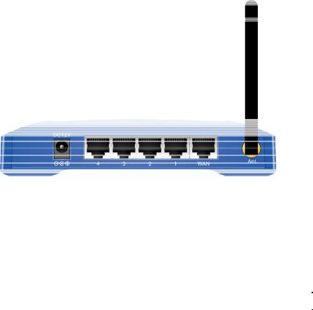
2. Rear Panel: Connection Ports
Port |
Functions |
|
|
|
|
DC 12V |
Connects the power adapter plug. |
|
|
|
|
LAN 1 |
|
|
|
|
|
LAN 2 |
Connects inside network group. |
|
|
||
LAN 3 |
||
|
||
LAN 4 |
|
|
|
|
|
WAN |
Connects inside network group or outside internet. |
|
|
|
|
Ant. |
Connects antenna. |
|
|
|
|
|
Table 2: Connection Ports |
1.3 Factory Default Settings
|
Setting |
Wireless Access Point |
|
|
Device Name |
WL-5470AP |
|
|
|
|
|
|
|
|
|
|
SSID |
Default value: airlive |
|
|
|
|
|
|
Channel |
Default value: 13 |
|
|
|
|
|
|
WEP |
Default value: Disabled |
|
|
|
|
|
|
IP Address |
Default value: 192.168.100. 252 |
|
|
|
|
|
|
DHCP Server |
z In AP, Client, Repeater and GW mode, the default DHCP Server is |
|
|
|
disabled, Please set your PC's IP to the same subnet as the AP to |
|
|
|
access the AP. |
|
|
|
In WISP, mode, the default DHCP server is enabled. Please restart |
|
|
|
your PC to renew the IP address. |
|
|
|
|
|
|
DHCP Server IP Range |
192.168.100.100~192.168.100.200 |
|
|
|
|
|
|
|
Table 3: Default Setting |
|
|
|
AirLive WL_5470AP User’s Manual |
|
3

Chapter II: Hardware Connection
Note: Before you starting hardware connection, you are advised to find an appropriate location to place the Access Point. Usually, the best place for the Access Point is at the center of your wireless network, with line of straight to all your wireless stations. Also, remember to adjust the antenna; usually the higher the antenna is placed the better will be the performance.
1.Connect to your local area network: connect an Ethernet cable to one of the Ethernet port.
2.(LAN1 to LAN4) of this Wireless Access Point, and the other end to a hub, switch, router, or another wireless access point.
3.Power on the device: connect the included AC power adapter to the Wireless Access Point’s power port and the other end to a wall outlet.
2.1 Check the LED:
The Power and LAN # LED should be ON. LAN# LED will even blink if there is traffic.
The Link/Act LED will be on in static when associated with a station and blink whenever this AP receives data packets in the air.
If the Status LED glows after self-test, it means the Wireless Access Point fails on self test. Please ask your dealer for technical support.
4.Please make sure your computer IP is in the same subnet as the AP (i.e. 192.168.100.x).
5.please make sure your computer has wireless network adapter installed.
6.Open the web browser and enter http://192.168.100.252/.
AirLive WL_5470AP User’s Manual
4
Chapter III: About the Wireless Operation Modes
The WL-5470AP v2 device provides all 7 modes of wireless operational applications with:
1Access Point Mode.
2Client Mode.
3Bridge Mode.
4WDS Repeater Mode.
5Universal Repeater Mode.
6WISP (Client Router) Mode.
7WISP + Universal Repeater Mode.
8GW Mode
This device is shipped with configuration that is functional right out of the box. If you want to change the settings in order to perform more advanced configuration or even change the mode of operation, you can use the web-based utility provided by the manufacturer as described in the following sections.
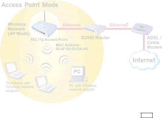
3.1 Access Point Mode
When acting as an access point (default setting), this device connects all the stations (PC/notebook with wireless network adapter) to a wired network. All stations can have the Internet access if only the Access Point has the Internet connection. See the sample application below.
To set the operation mode to “Access Point”, please go to “Mode JAP” and click the Setup button.
AirLive WL_5470AP User’s Manual
5
3.2 Client Mode (Infrastructure)
If set to Client (Infrastructure) mode, this device can work like a wireless station when it’s connected to a computer so that the computer can send packets from wired end to wireless interface.
Refer to the illustration below. This station (AP1 plus the connected computer 1) can associate to another Access Point (AP2), and then can have the Internet access if the other Access Point (AP2) has the Internet connection.
AirLive WL_5470AP User’s Manual
6

To set the operation mode to “Client (Infrastructure)”, Please go to “Mode JClient” and click the Setup button.
In the “Network Type” field, select as “infrastructure” for configuration.
3.3 Client Mode (Ad-hoc)
If set to the Client (Ad-hoc) mode, this device can work like a wireless station when it is connected to a computer so that the computer can send packets from wired end to wireless interface. You can share files and printers between wireless stations (PC and laptop with wireless network adapter installed).
See the sample application below.
AirLive WL_5470AP User’s Manual
7

To set the operation mode to “Client (Ad-Hoc)”, Please go to “Mode JClient” and click the Setup button. In the “Network Type” field, select as “infrastructure” for configuration.
3.4 Bridge Mode
In this mode, 2 access points in two remote locations connect to each other to provide a wireless bridge between 2 remote LANs. It is mostly used by enterprise to connect 2 remote office's network together. The bridge modes are connected by using either the WDS (Wireless Distribution System) or Ad-Hoc topology.
This feature is also useful when users want to bridge networks between buildings where it is impossible to deploy network cable connections between these buildings.
To set the operation mode to “Bridge”, Please go to “Mode JBridge” and click the Setup button for configuration.
AirLive WL_5470AP User’s Manual
8

3.5 WDS Repeater Mode
A repeater's function is to extend the wireless coverage of another wireless AP or router. For WDS repeater to work, the remote wireless AP/Router must also support WDS function.
To set the operation mode to “WDS Repeater”, Please go to “Mode JWDS Repeater” and click the Setup button for configuration.
3.6 Universal Repeater Mode
A universal repeater can also extend the wireless coverage of another wireless AP or router. But the universal repeater does not require the remote device to have WDS function. Therefore, it can work with almost any wireless device.
Note: When you are using the universal repeater mode, please make sure the remote AP/Router‘s WDS function is turned off.
AirLive WL_5470AP User’s Manual
9

To set the operation mode to “Universal Repeater”, Please go to “Mode JUniversal Repeater” and click
the Setup button for configuration.
3.7 WISP ( Client Router) Mode
zWISP (Client Router) mode
In WISP mode, the AP will behave just the same as the Client mode for wireless function. However, Router functions are added between the wireless WAN side and the Ethernet LAN side. Therefore, The WISP subscriber can share the WISP connection without the need for extra router.
To set the operation mode to “WISP”, Please go to “Mode JWISP” and click the Setup button for configuration.
AirLive WL_5470AP User’s Manual
10
 Loading...