


WL-350HD

A
irCam
W
Auto Light Sensor Wireless-G
MegaPixel IP Camera
L-350HD
User’s Manual

Copyright and Disclaimer
Copyright & Disclaimer
No part of this publication may be reproduced in any form or by any means, whether
electronic, mechanical, photocopying, or recording without the written consent of OvisLink
Corp.
OvisLink Corp. has made the best effort to ensure the accuracy of the information in this
user’s guide. However, we are not liable for the inaccuracies or errors in this guide.
Please use with caution. All information is subject to change without notice
All Trademarks are properties of their respective holders.

FCC Statement
Federal Communication Commission Interference Statement
This equipment has been tested and found to comply with the limits for a Class B digital
device, pursuant to Part 15 of the FCC Rules. These limits are designed to provide
reasonable protection against harmful interference in a residential installation. This
equipment generates, uses and can radiate radio frequency energy and, if not installed and
used in accordance with the instructions, may cause harmful interference to radio
communications. However, there is no guarantee that interference will not occur in a
particular installation. If this equipment does cause harmful interference to radio or
television reception, which can be determined by turning the equipment off and on, the user
is encouraged to try to correct the interference by one of the following measures:
Reorient or relocate the receiving antenna.
Increase the separation between the equipment and receiver.
Connect the equipment into an outlet on a circuit different from that to which the
receiver is connected.
Consult the dealer or an experienced radio/TV technician for help.
FCC Caution
Any changes or modifications not expressly approved by the party responsible for
compliance could void the user's authority to operate this equipment. This device complies
with Part 15 of the FCC Rules. Operation is subject to the following two conditions: (1) This
device may not cause harmful interference, and (2) this device must accept any
interference received, including interference that may cause undesired operation. For
product available in the USA/Canada market, only channel 1~11 can be operated.
Selection of other channels is not possible.
This device and its antenna(s) must not be co-located or operation in conjunction with any
other antenna or transmitter.
FCC Radiation Exposure Statement
This equipment complies with FCC radiation exposure limits set forth for an uncontrolled
environment. This equipment should be installed and operated with minimum distance
20cm between the radiator & your body.
AirLive AirCam WL-350HD User’s Manual

Table of Contents
1. Overview...................................................................................................3
1.1 Introduction..............................................................................3
1.2 Features ..................................................................................3
1.3 Product Specification ...............................................................3
1.4 System Requirement ...............................................................4
2. Package Contents and Installation ........................................................5
2.1 Hardware Overview .................................................................6
2.2 Hardware Installation...............................................................7
2.3 Connect to IP Camera .............................................................8
3. Using IP Camera via Web Browser ......................................................10
3.1 Windows Web Browser .........................................................10
3.2 Mac Web Browser .................................................................11
4. Setting up Wireless Configuration .......................................................13
5. Operating IP Camera via Mobile Phone ...............................................15
5.1 Mobile Phone Viewing ...........................................................15
5.2 Using IP Camera via iPhone .................................................16
6. MSN Messenger .....................................................................................17
7. Configuration of Main Menu .................................................................22
7.1 Live View ...............................................................................22
7.2 Setting ...................................................................................24
7.3 Client Setting .........................................................................25
7.4 Image Setup ..........................................................................26
8. Setting-Basic..........................................................................................27
8.1 System...................................................................................27
8.2 Camera..................................................................................31
8.3 Network .................................................................................43
i
AirLive AirCam WL-350HD User’s Manual

8.4 Security..................................................................................58
8.5.HTTPS...................................................................................60
8.6.IP Filter ..................................................................................61
9. Setting-Advanced ..................................................................................63
9.1 FTP Client..............................................................................63
9.2 SMTP.....................................................................................68
9.3 Network Storage ....................................................................75
9.4 HTTP Event ...........................................................................79
9.5 Schedule................................................................................82
9.6 Alarm Buffer...........................................................................83
9.7 Motion Detection....................................................................85
9.8 Audio Detection .....................................................................86
9.9 System Log............................................................................87
10. Appendix..........................................................................................88
A. Frame-rate and Bitrate Table............................................................88
B. Storage Requirement Table..............................................................92
AirLive AirCam WL-350HD User’s Manual
ii

1. Overview
1
This user’s guide explains how to operate this camera from a computer. User should read
this manual completely and carefully before you operate the device.
1.1 Introduction
Still couldn’t find a way to watch your children or the elders when you are in busy or on duty?
Or just need an easy solution for monitoring your office, store or garage? WL-350HD, with
its compact size and wireless network technology, moves the “surveillance” from a complex
task to a simply “Plug and Play” job.
1.2 Features
This manual will illuminate the steps of how to setup and operation this IP camera, so you’ll
also soon be enjoying the benefits of these product features:
Compact and thin design
UPnP for fast and easy installation
Support 6pcs high illumination LED
1.3 megapixel progressive scan CMOS
Multiple H.264, Motion JPEG and MPEG-4 video streams
Supports Two-Way Audio
Mobile Phone Live Viewing
Support Windows Live Messenger
32 channel surveillance software
1.3 Product Specification
Models
Image sensor
Lens
Digital Zoom
Min Illumination
IR working distance
Video Compression
Resolutions
AirCam WL-350HD
1/4” Progressive scan CMOS 1.3 Megapixel sensor
F1.8, 4.2 mm
10x digital
0 Lux at F2.0 with Night-vision LEDs on
5 M
Motion JPEG
MPEG-4 Part2 (ISO/IEC 14496-2), Profile: SP
H.264 BP
UP to 1280 x 1024
3

Frame rate
Video streaming
Audio
Wireless
Alarm and event
management
Casing
Power
Operating
conditions
Supported
protocols
Dimensions
(HxWxD) and
weight
Approvals
Motion JPEG: Up to 15 fps at 1280x1024
Up to 30 fps at 640x480
MPEG-4: Up to 15 fps at 1280x1024
Up to 30 fps at 640x480
H.264: Up to 15 fps at 1280x1024
Up to 30 fps at 640x480
Simultaneous Motion JPEG, MPEG-4, H.264 and
3GPP (4 streaming)
Two-way (full duplex)
IEEE 802. 11b/g
Input: alarm buffer, motion detection, audio detection
Output: network storage, FTP, SMTP, HTTP event
Pre-and post alarm buffer
PC+ABS casing
12V DC, 1A, Max 12W
0 ~ 50 ℃ (32 ~ 122 ℉)
Bonjour, TCP/IP, DHCP, PPPoE, ARP, ICMP, FTP,
SMTP, DNS, NTP, UPnP, RTSP, RTP, HTTP, TCP,
UDP, 3GPP/ISMA RTSP
104 x 63 x 35 mm (4.1” x 2.5” x 1.4”)
116.5 g (0.3 lb) excl. power supply
CE, FCC, RoHS
1.4 System Requirement
For normal operation and viewing of the network camera, it’s recommended that your
system meet these minimum requirements for proper operation:
Item Requirements
CPU Pentium 4 2.8GHz (or equivalent AMD)
Graphic Card 256 MB RAM graphic cards(or equivalent on-board graphic
cards)
RAM 1G
Operating
System
Web Browser Internet Explore 6 or later
Note: Please keep updating the latest Windows software and service package. (Ex: Net
Framework, Windows Media Player, Enhance ActiveX Security)
Windows 2000, Windows 2003, Windows XP, Windows Vista,
Windows 7, and Mac OS X Leopard
4
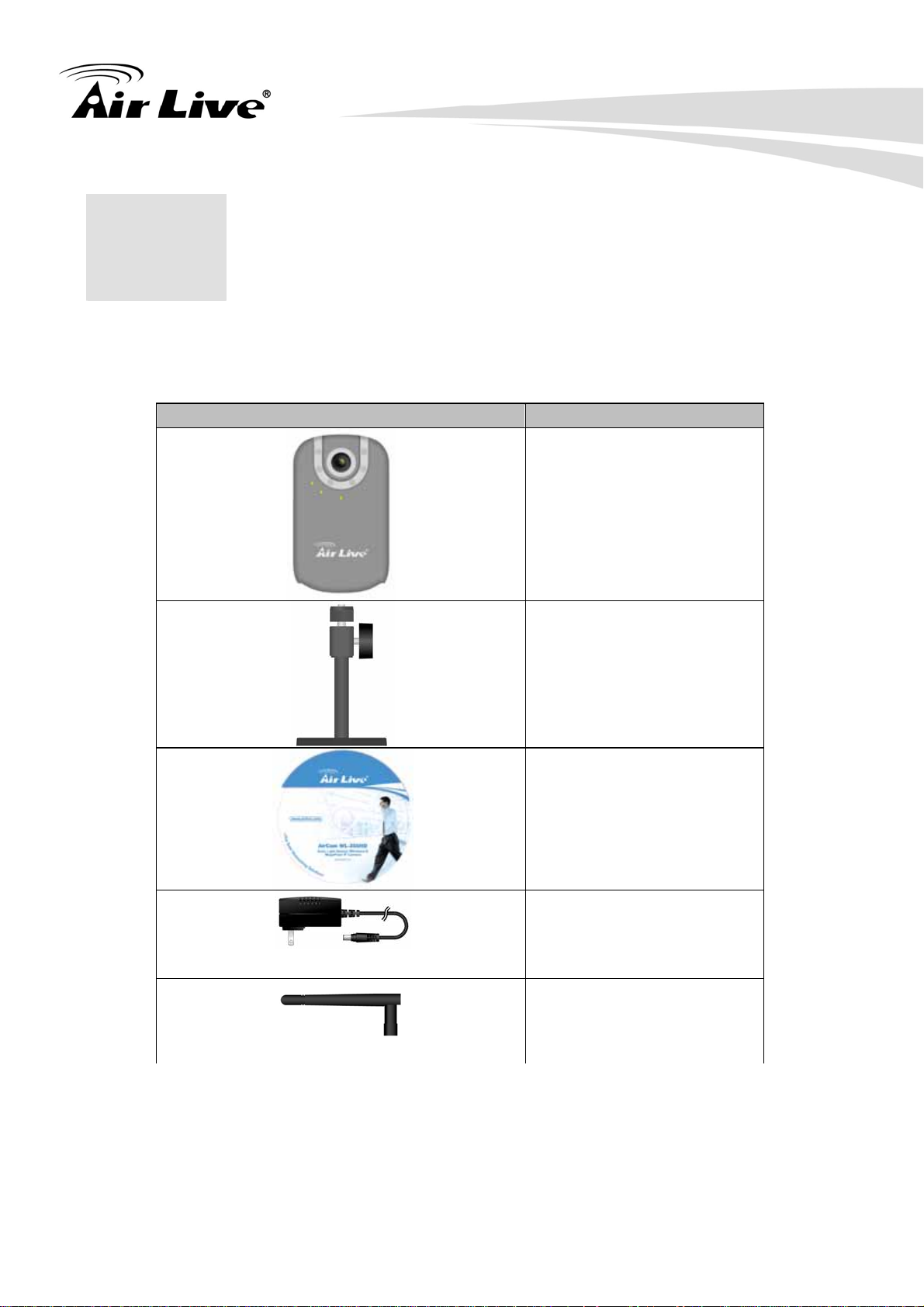
2. Package Contents
2
User can find the following items in the package as below:
and Installation
Item Descriptions
1. WL-350HD is the main
element of the product.
2. Stand and Mounting
Bracket
3. Bundle CD include Setup
Wizard II, Messenger Plug-in,
Quick Start Guide, User Manual
and other tools
4. Power Adapter dedicates
12V DC electric power output to
Network Camera.
5. Antenna
5
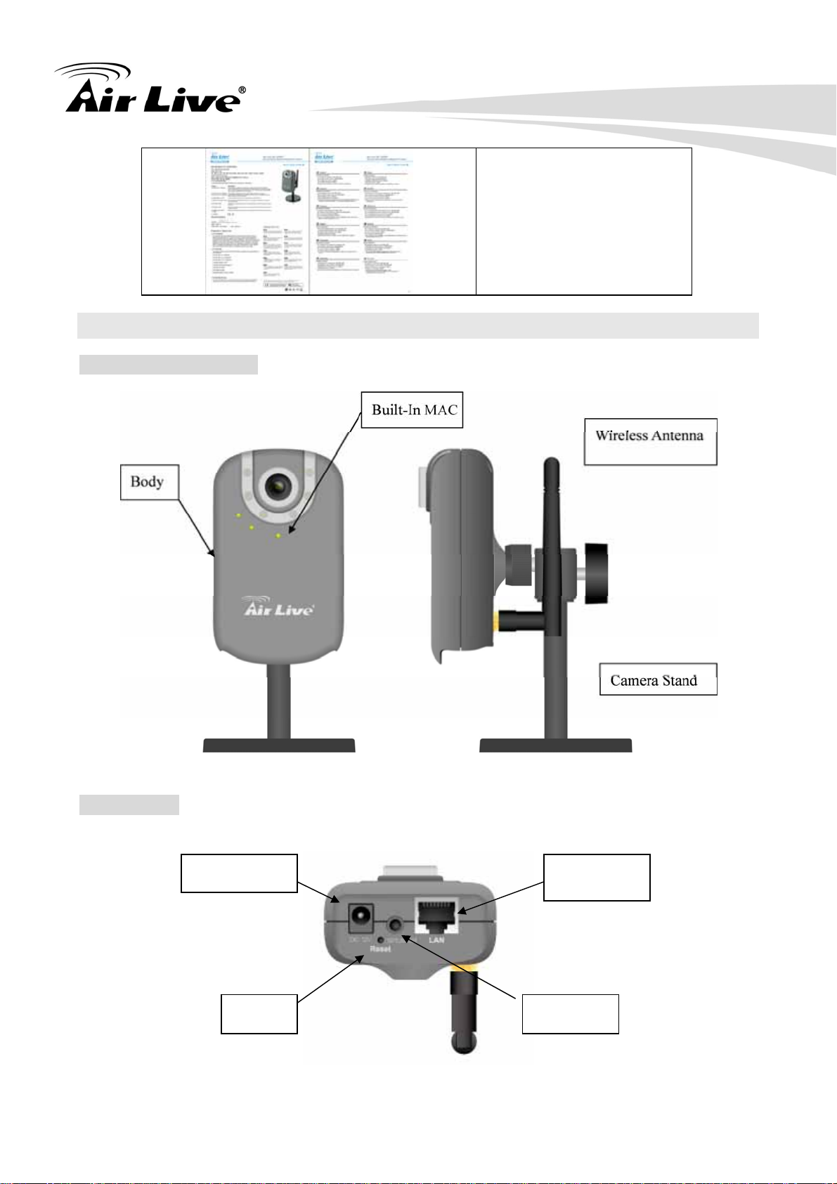
2.1 Hardware Overview
Front and Lateral Side
6. Quick Start Guide provides
important information and
instructions for installing this
device.
Bottom Side
Power In
Network
Audio Out Reset
6
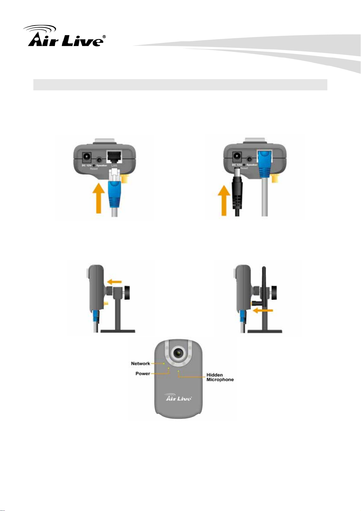
2.2 Hardware Installation
Follow these steps to install the WL-350HD on your Ethernet:
1. Install Ethernet
Cable
2. Install Power
Adapter
3. Install Stand
4. Install Antenna
Note:
Press the Reset Button to reboot the camera.
Hold the Reset Button for 10 seconds to restore the camera to default
7

2.3 Connect to IP Camera
A. Insert the bundle CD into your PC/Laptop
B. Auto Run Screen then shows up, click “Install Driver & Utility Æ IP Search Tool” to
install the configuration tool software
C. After complete installation, run the configuration tool software
8
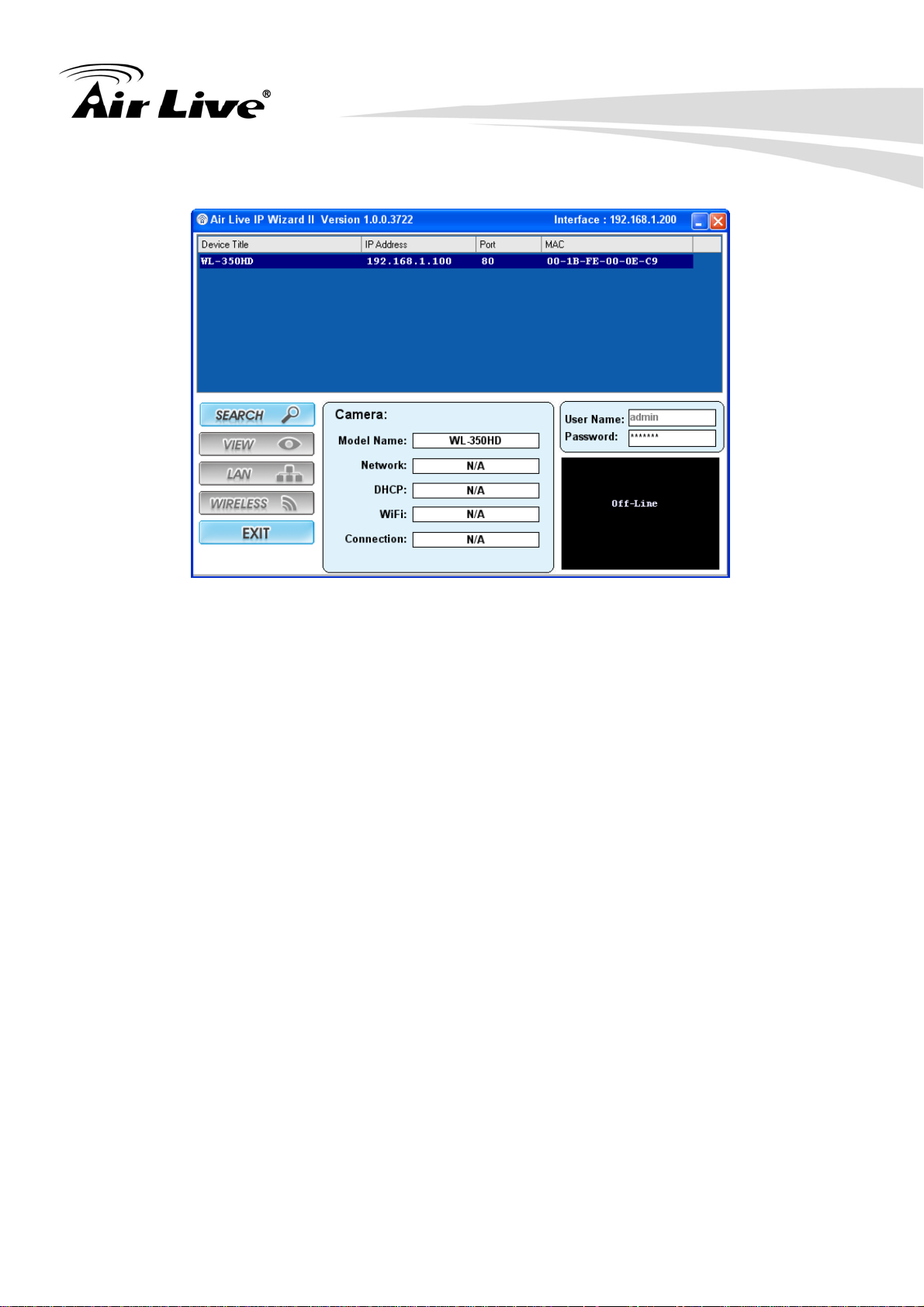
D. The Software scans the network and finds the IP Camera, then list in the dialog box.
E. If the Camera’s IP address is in the same IP segment as your LAN, select the founded IP
Camera and double click on the item, then the default browser will show up and connect
to the IP camera’s Web automatically.
9
3. Using IP Camera via
3
Web Browser
3.1 Windows Web Browser
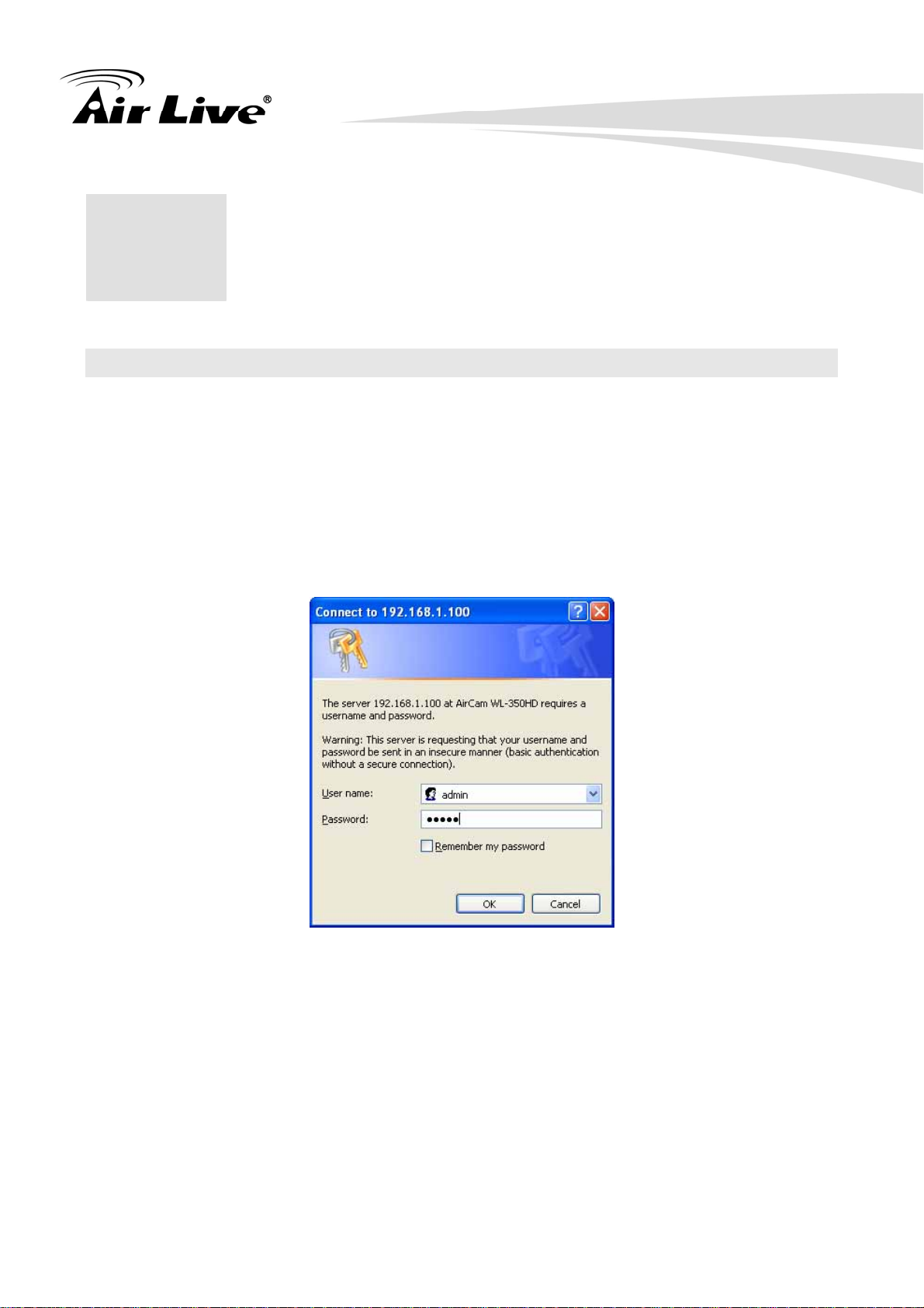
A. Open your web browser, and enter the IP address or host name of the IP camera in the
Location / Address field of your browser.
Note: If you only want to view the video without accessing Setting screen, enter
“http://<IP>/index2.htm” as your web URL.
B. Use the default account “admin” and default password “airlive”.
Note : The default user name “admin” and the password “airlive” are set at the factory for
the administrator. You can change them in the Account Menu. (Please check “Setting →
Basic → Security → Account”)
C. The monitor image will be displayed in your browser. In the far left side of main
configuration are Setting, Client Setting, and Image Setup. For more details, you can
check Chapter 7.2、Chapter 7.3、Chapter 7.4 and Chapter 7.5.
10
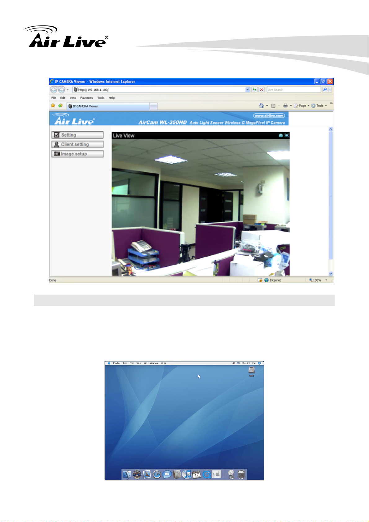
3.2 Mac Web Browser
A. Click the Safari icon, and enter the IP address of the IP camera in the Location / Address
field of your browser.
Note: If you only want to view the video without Setting screen “http://<IP>/index2.htm” as
your web URL.
11
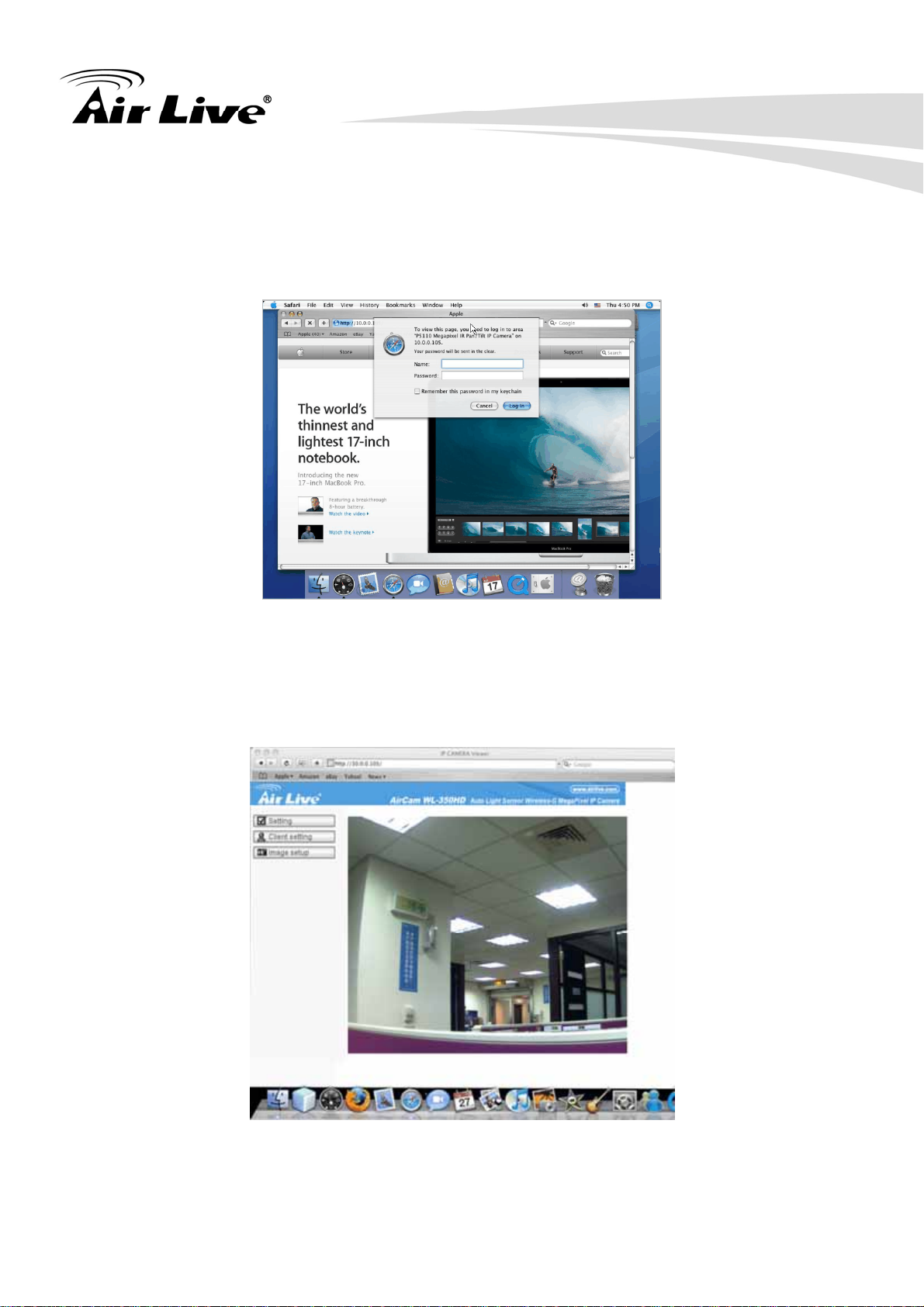
B. Enter the default account “admin” and default password “airlive”.
Note: The default user name “admin” and the password “airlive” are set at the factory for
the administrator. You can change them in the Account Menu (Please check “Setting →
Basic → Security → Account”)
C. The monitor image will be displayed in your browser. In the far left side of main
configuration are Setting, Client Setting, and Image Setup. For more details, you can
check Chapter 7.2、Chapter 7.3、Chapter 7.4 and Chapter 7.5.
12
4. Setting up Wireless
4
The wireless network has to be set up by using cable network connection. After setting the
camera correctly, the wireless function can work without cable network connection. Please
follow the setting process below step by step:
A. Connect IP Camera with Ethernet connection.
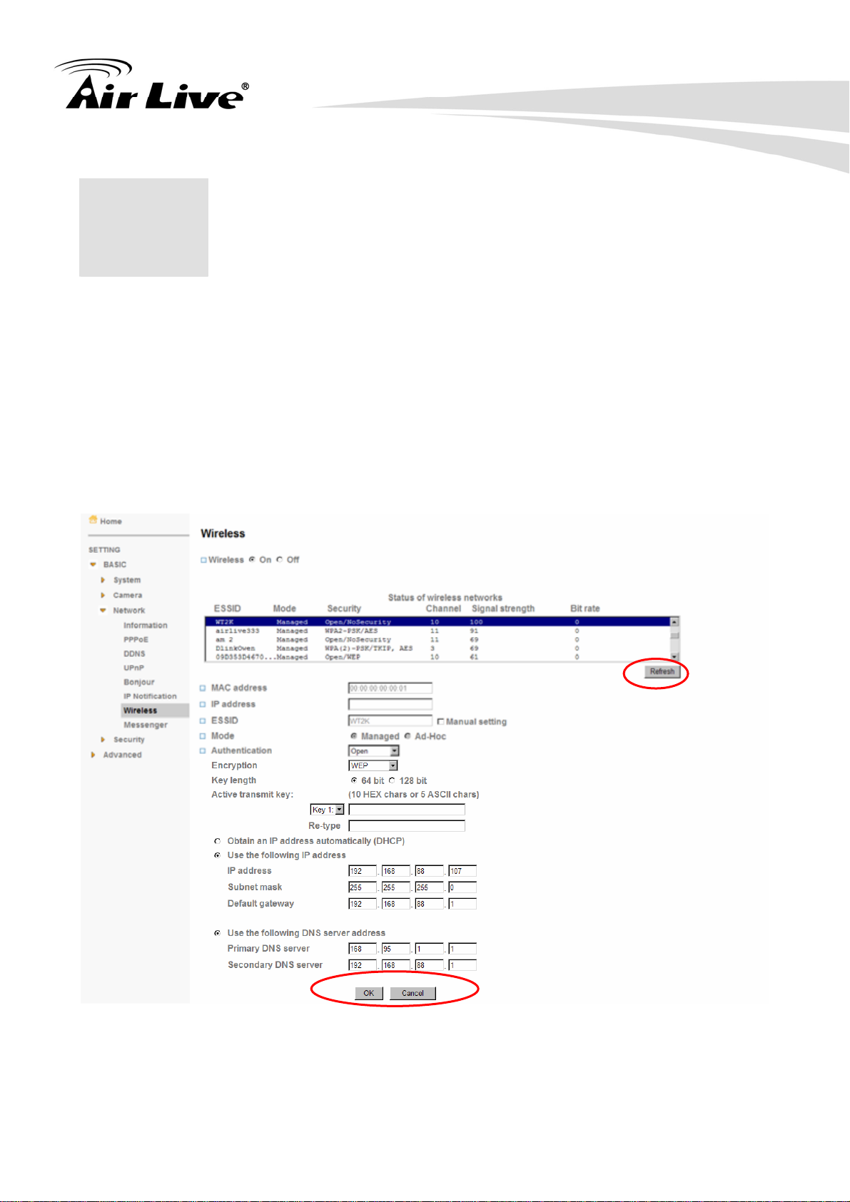
B. Go to “Setting → Basic → Network → Wireless,” choose option “On”. You will see the
wireless Setting screen.
Configuration
C. Then click “Refresh”. All access points (AP) around you will show up.
D. Select the AP you wish to connect.
13
E. Enter password at active transmit key if you need. If you don't know the setting of the
wireless AP, please ask your network administrator.
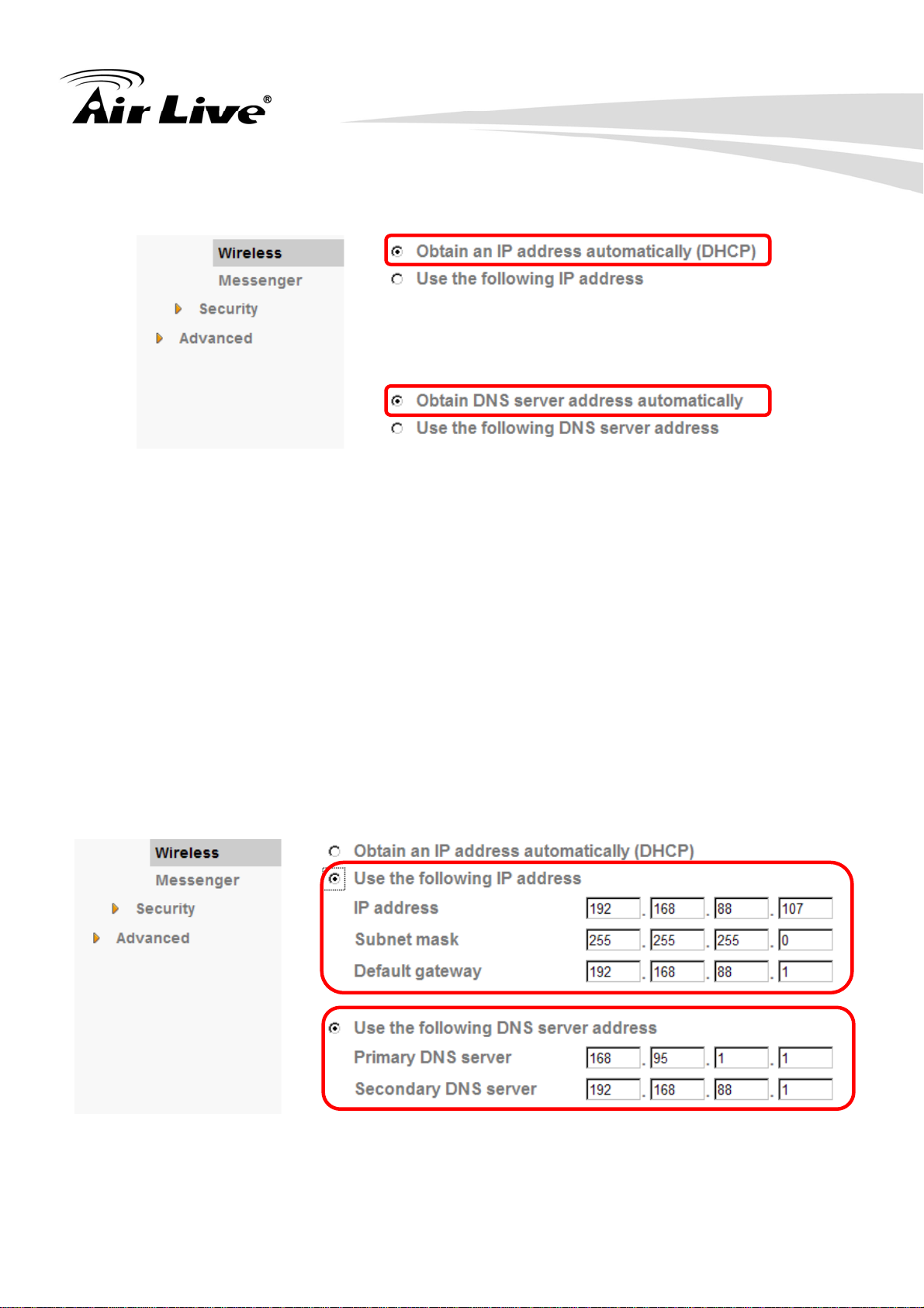
F. Choose the option of Obtain an IP address automatically (DHCP) and Obtain DNS
server address automatically.7. Otherwise, Choose Use the following IP address and
Use the following DNS sever address.
Use the following IP address: Select this when the fixed IP address is set.
z IP address: Enter the IP address of the device.
z Subnet mask: Enter the subnet mask.
z Default gateway: Enter the default gateway.
Use the following DNS server address: Select this when you set the fixed address
as the IP address of DNS server.
z Primary DNS server: Enter the IP address of the primary DNS server.
z Secondary DNS server: Enter the IP address of the secondary DNS server, if
necessary.
14

5. Operating IP Camera
5
5.1 Mobile Phone Viewing
5.1.1 3G Mobile Phone Streaming Viewing
For 3G mobile phone viewing, type “ rtsp://<IP>:<PORT>/video.3gp ” into your 3G
Streaming Link. <IP> is the Public IP address of your IP camera; <PORT> is the RTSP port
of your IP camera (Default value is 554.) Example: rtsp://100.10.10.1:554/video.3gp
Note: You can also use RTSP clients (RealPlayer, VLC, QuickTime Player…etc.) to view
RTSP streaming, just type in “rtsp://<IP>:<PORT>/video.3gp” as the Player URL
5.1.2 2.5G Mobile Phone WAP Viewing
For 2.5G mobile phone viewing, type “http://<IP>/mobile.wml” into your 2.5G WAP Browser.
<IP> is the Public IP address of your IP camera.
via Mobile Phone
5.1.3 2.5G Mobile Phone Browser Viewing
For 2.5G mobile phone viewing, type “http://<IP>/mobile.wml ” into your 2.5G Web Browser.
<IP> is the Public IP address of your IP camera.
15
5.2 Using IP Camera via iPhone
You can access to your IP camera via your iPhone. Please follow the setting process below.
Then you can use the Web UI via iPhone.
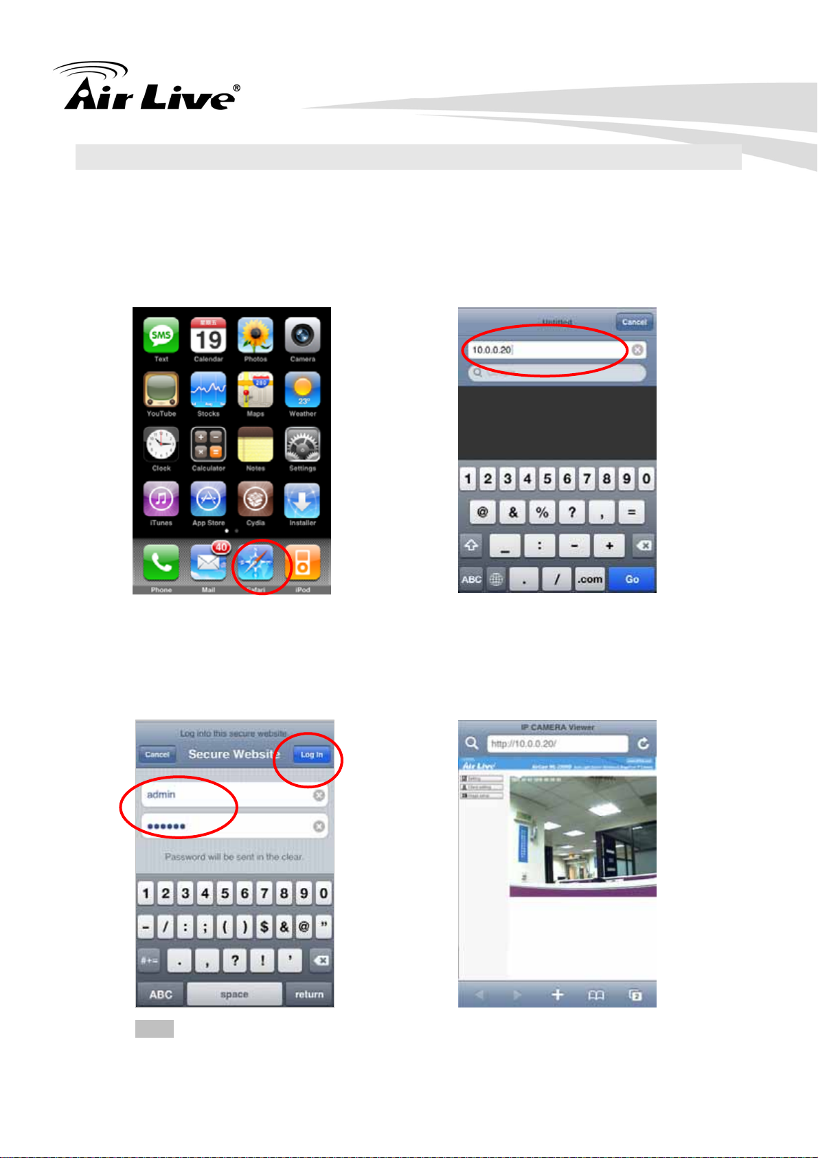
A. Select Safari function
B. Type IP address in your web link.
C. Type name and password.
Default value is admin / airlive.
Then click Login In
D. The Web User Interface and
live image will show up in the
middle of screen.
Note: The image is continuous snapshots, not video. Thus, live image can’t be
recorded here.
16
6. MSN Messenger
6
Please follow the following steps to set up the Messenger function.
A. Download free MSN software and create a new MSN account (Camera at home) for
Microsoft Live Messenger.
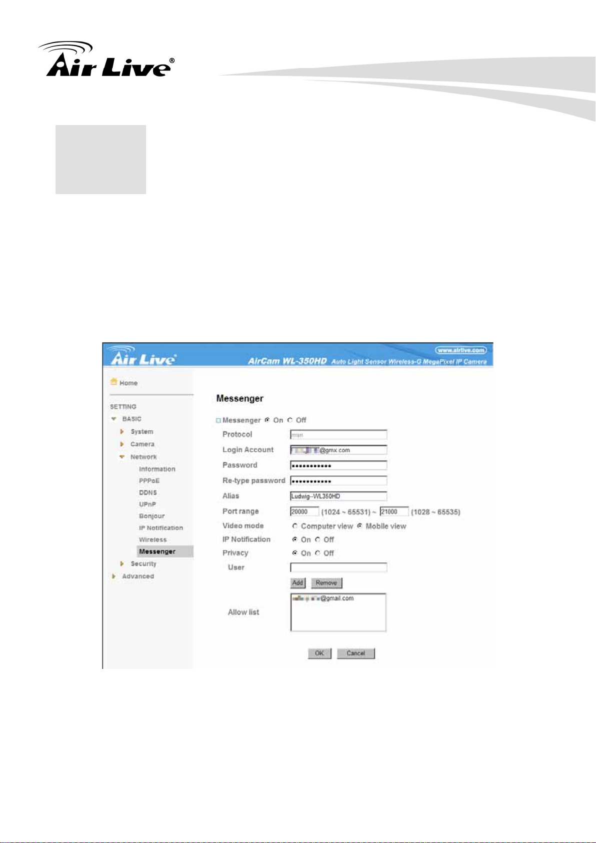
B. Go to “Setting→Basic→Network→Messenger,” set the Messenger to “ON” . Then, fill out
Login Account and Password (Camera at home).
C. The Alias will be shown as the nickname on the contact list when you login with the
messenger account that be added to the Allow list.
D. If your router has firewall function, you have to set the Port Range on this setting page in
17

accordance with the one of firewall.
E. Choose the Video Mode, decide the live view image of messenger received from
Computer View (H.264/MPEG-4) or Mobile View (3GPP).
F. Choose On at the option of IP Notification. If this feature switches to On, camera will
send IP notification to the users who are allowed.
G. Choose On at the option of Privacy. After you choose On at the privacy option, you can
set the Allow list.
H. Insert the bundle CD to your PC/Laptop and install the Messenger Plug-in (Install Driver
& Utility Æ Messenger Plug-in) for retrieving and adjusting the image from of the IP
camera via Messenger.
I. Login Messenger with the account that be added to the Allow list. Then, add the new
MSN account (Camera at home )
J. The Camera at home will show up with its Public IP and Private IP if the option of IP
Notification is “On”. ( You can enter “Ping” to show up with Public IP and Private IP. )
18
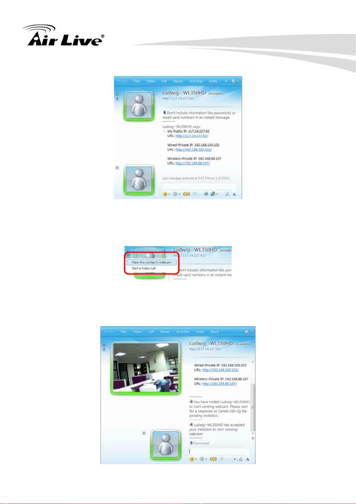
K. Click on the small camera icon. Then, choose “View this contact's webcam”.
L. The IP Camera will accept your invitation; the live video will show up in the screen after
few seconds.
19

M. Click Action button and choose Start Control Panel to use control panel.
N. The dialog box will show up with “This application is not part if Window Live
Message…….” Tick the box of “Don’t show me this again” and click OK.
O. The IP Camera will accept your invitation to start Control Panel.
20
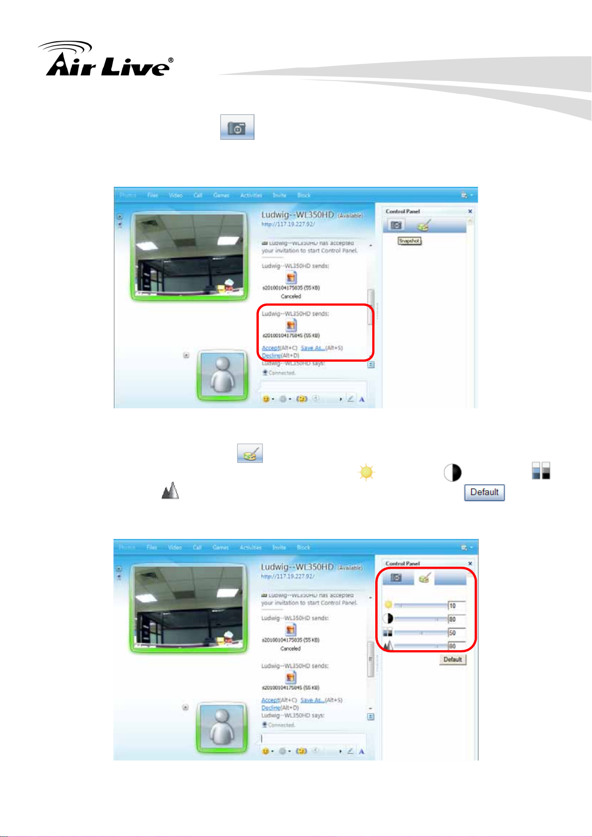
P. You can click Camera icon to snapshot then the picture will send to you
immediately.
Q. You can click paint palette icon showing up with tool bar to set up image. Then,
you can use the tool bar to optimize video Brightness , Contrast , Saturation
and Sharpness . After the adjustment of all setting, you can still click to
make the setting back to the original setting.
21
7. Configuration of Main
7
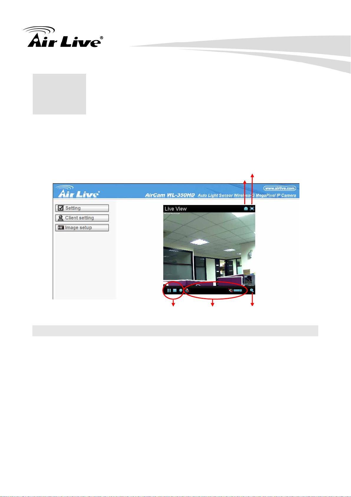
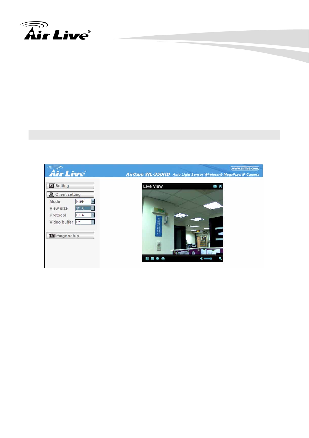
In the left side of main configuration are Setting, Client setting, and Image setting. For
more details, please check Chapter 7.2、Chapter 7.3、Chapter 7.4.、Chapter 7.5.
In the right side, you can control Live View in your main Browser. The functions include
Snapshot, Open digital zoom, Audio, and Video Play.
Menu
Full screen
Snapshot
Open digital zoom Video Play Audio Play
7.1 Live View
7.1.1 Snapshot
You can capture a still image shot by clicking the camera icon and save it in the operating
computer.
22
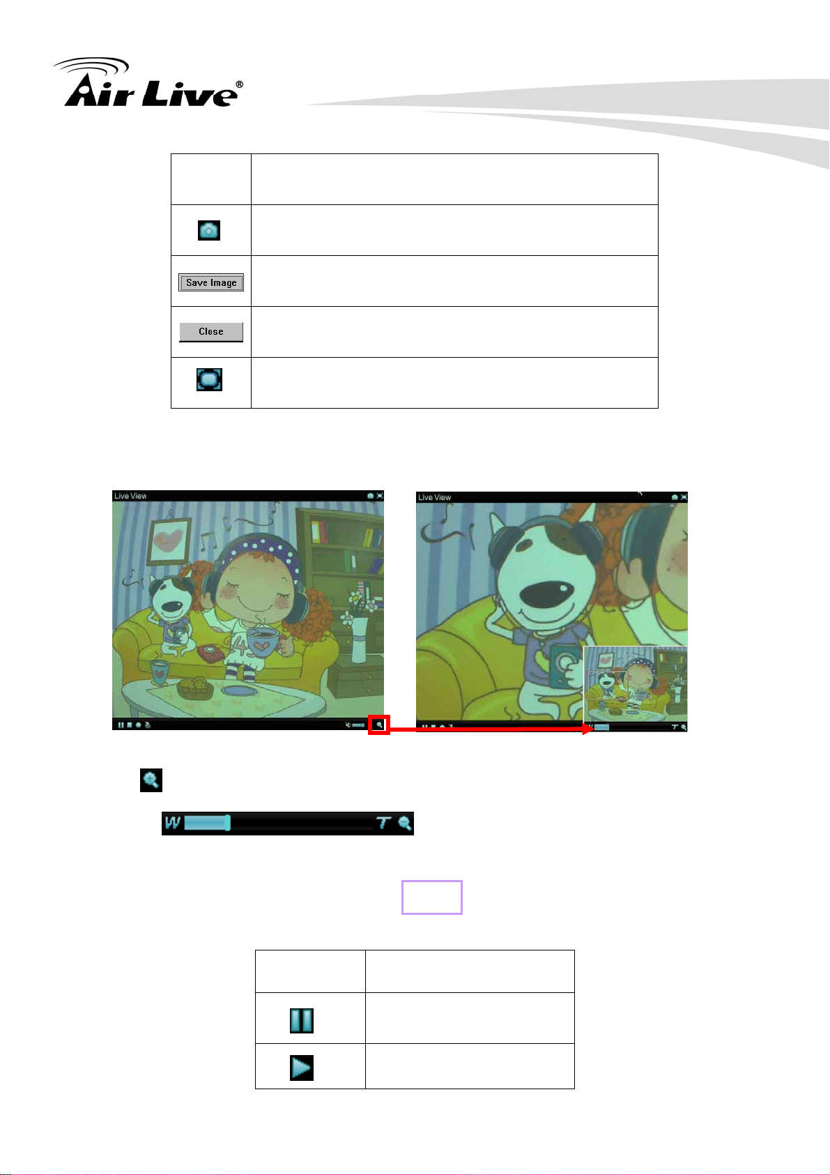
Symbols Meaning
a snapshot window appears after clicking the icon
save the picture captured by snapshot into your computer
Return to the view screen
full screen
7.1.2 Digital zoom in / out the image via the monitor window
A. Click to display the digital zoom in window.
B. Pull the to adjust the digital zoom range, and it will be
showed on the above window.
C. Use the left click of your mouse to move to anywhere in the window area.
7.1.3 Video play buttons
Symbols Meaning
Pause the current video
Play the video
23
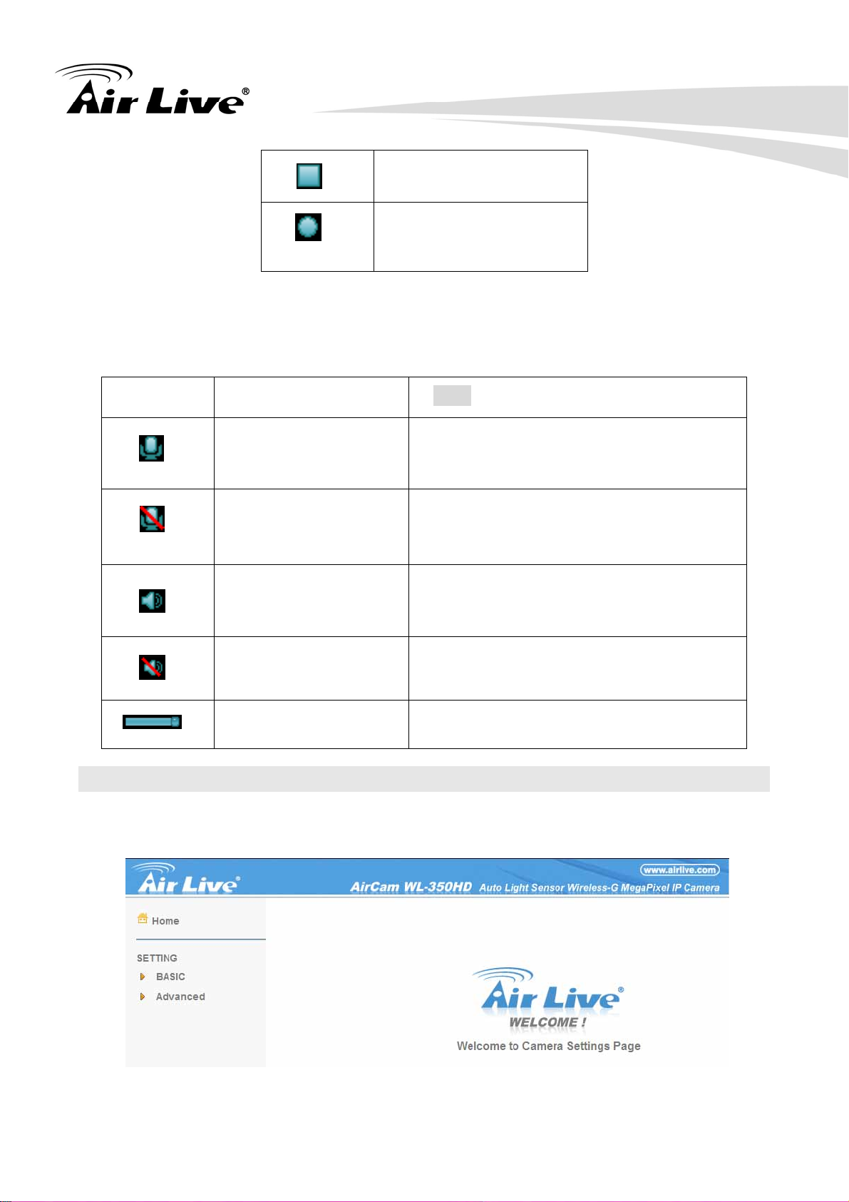
Stop the current video
Record the current
video
Note: Concerning the recording storage requirement of your hard disk, please refer to the
CHAPTER 10. APPENDIX / B. Storage Requirement Table.
7.1.4 Audio buttons
Symbols Meaning Note
Speakers turned on
Speakers turned off
Mute off
mean you can broadcast to the
connected IP camera(s) via the Ethernet
using your microphone
mean you can’t broadcast to the
connected IP camera(s) via the Ethernet
using your microphone
mean the speakers of your computer
are turned on to receive the sounds
from the connected IP camera(s)
Mute on
Volume control bar
mean the speakers of your computer
are turned off to receive the sounds
from the connected IP camera(s)
mean you can adjust the sound
volume by the control bar
7.2 Setting
This function is only for the Administrator. Click “Setting” on the home page of web user
interface to get into the Basic and Advanced Settings menu.
24
7.2.1 Basic
Click Basic, there are sub-menus including System, Camera, Network, and Security. For
more information, you can see Chapter 8.1、Chapter 8.2、Chapter 8.3 and Chapter 8.4.
7.2.2 Advanced
Click Advanced, there are sub-menus including FTP Client, SMTP, Network storage, HTTP
event, Schedule, Alarm buffer, Motion Detection, Audio Detection, and System Log. For
more information, please see Chapter 9.
7.3 Client Setting
This function is only for the client. Click this button to control Mode, View Size, Protocol,
and Video Buffer.
7.3.1 Mode
Click the pull-down box to choose video compression mode of LIVE VIEW among H.264,
MPEG-4, and MJPEG.
Note: As long as the operating system not able to afford loading under H.264 mode, please
downgrade the mode to MPEG-4 or MJPEG.
7.3.2 View Size
Select the desired view size of image resolution among 1/4X, 1/2X, and 1X.
7.3.3 Protocol
Select the transferring protocol among TCP, UDP, and HTTP.
7.3.4 Video Buffer
Turn the Video Buffer function On / Off. The Video Buffer function makes the streaming
more smoothly in unsteady network environment, but might cause a little delay in live
viewing
25

7.4 Image Setup
The tool bar can be adjusted to optimize video Brightness, Contrast, Saturation and
Sharpness.
7.4.1 Brightness
The value range is 0~99. The higher value the brightness is, the brighter the image is.
7.4.2 Contrast
The value range is 0~99. The contrast is a measure of a display system, defined as the
white to black that the system is capable of producing. The higher value the contrast is, the
more delicate of color you can have.
7.4.3 Saturation
The value range is 0~99. The saturation of a color is determined by a combination of light
intensity and how much it is distributed across the spectrum of different wavelengths. The
higher value the saturation is, the more colorful the image will be.
7.4.4 Sharpness
The value range is 0~99. It applies image processing techniques to adjust the sharpness of
live view. However, higher the value is, more the noise is.
7.4.5 Default
After the adjustment of all setting, you can still click Default to make the setting back to the
original setting.
26
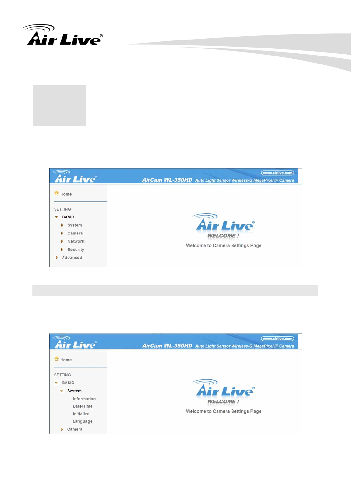
8. Setting-Basic
8
Click the Basic to display the sub-menus including System, Camera, Network, and
Security.
8.1 System
Click System to display the sub-menus including Information, Date / Time, Initialize, and
Language.
27
 Loading...