

Page 1

Agilent E6474A
Wireless Network
Optimization Platform
User’s Guide
Agilent Technologies
Page 2

Notices
© Agilent Technologies, Inc. 2004
No p art o f this manu al ma y be r epro duced in
any form or by any means (including electronic storage and retrieval or translation
into a foreign language) without prior agreement and written consent from Agilent
Technologies, Inc. as governed by United
States and international copyright laws.
Manual Part Number
E6474-90052
Edition
Fourth edition, April 2004
Printed in Singapore
Agilent Technologies
1400 Fountaingrove Parkway
Santa Rosa, CA 95403 USA
Acknowledgements
MapInfo ® is a registered trademark of
MapInfo Corporation.
Pentium ® is a registered trademark of Intel
Corporation.
Adobe ® is a trademark of Adobe Systems
Incorporated.
Windows XP, Windows 2000, and
Windows 98 are U.S. registered trademarks
of Microsoft Corporation.
iDEN ® is a registered trademark of Motorola, Inc.
All other trademarks are the property of
their respective holders.
Warranty
The material contained in this document is provided “as is,” and is subject to being changed, without notice,
in future editions. Further, to the maximum extent permitted by applicable
law, Agilent disclaims all warranties,
either express or implied, with regard
to this manual and any information
contained herein, including but not
limited to the implied warranties of
merchantability and fitness for a particular purpose. Agilent shall not be
liable for errors or for incidental or
consequential damages in connection with the furnishing, use, or performance of this document or of any
information contained herein. Should
Agilent and the user have a separate
written agreement with warranty
terms covering the material in this
document that conflict with these
terms, the warranty terms in the separate agreement shall control.
Technology Licenses
The hardware and/or software described in
this document are furnished under a license
and may be used or copied only in accordance with the terms of such license.
Restricted Rights Legend
If software is for use in the performance of a
U.S. Government prime contract or subcontract, Software is delivered and licensed as
“Commercial computer software” as
defined in DFAR 252.227-7014 (June 1995),
or as a “commercial item” as defined in FAR
2.101(a) or as “Restricted computer software” as defined in FAR 52.227-19 (June
1987) or any equivalent agency regulation or
contract clause. Use, duplication or disclosure of Software is subject to Agilent Technologies’ standard commercial license
terms, and non-DOD Departments and
Agencies of the U.S. Government will
receive no greater than Restricted Rights as
defined in FAR 52.227-19(c)(1-2) (June
1987). U.S. Government users will receive
no greater than Limited Rights as defined in
FAR 52.227-14 (June 1987) or DFAR
252.227-7015 (b)(2) (November 1995), as
applicable in any technical data.
Safety Notices
CAUTION
A CAUTION notice denotes a
hazard. It calls attention to an
operating procedure, practice, or
the like that, if not correctly
performed or adhered to, could
result in damage to the product
or loss of important data. Do not
proceed beyond a CAUTION
notice until the indicated
conditions are fully understood
and met.
WARNING
A WARNING notice denotes a
hazard. It calls attention to an
operating procedure, practice,
or the like that, if not correctly
performed or adhered to, could
result in personal injury or
death. Do not proceed beyond a
WARNING notice until the
indicated conditions are fully
understood and met.
2 Agilent E6474A User’s Guide
Page 3

Welcome to Agilent E6474A Wireless Network Optimization Platform
Thank you for choosing Agilent Technologies. In this User’s
Guide, you will find the instructions you need to setup the
hardware and begin using the software to take measurements.
About this guide
This guide contains installation and operating instructions for
the Agilent E6474A Wireless Network Optimization Platform
software, as well as instructions for using the Agilent E6473B
High Speed Direct Connect Hub.
See this chapter For this information
1 Get Ready A list of tasks to perform before you get started.
2 Install the Software Instructions for Installing the E6474A software.
3 Set Up Your System Setup instructions and cable connections for each
component of your systems.
4 Use Your System • Powering up systems.
• Starting the software.
5 Get Results Fast • Using the Quick Basics to get started learning to
use the E6474A.
• Accessing and using online help.
6 Get Assistance, If You
Need It
Appendix A, “Safety
and Regulatory
Information”
Appendix B,
“Connection Panels
and LED Indicators”
• Getting telephone support.
• Frequently asked questions.
• Returning systems for service.
• Solving problems.
• Contacting customer support.
• Updating E645xx receiver firmware.
Information to help you to use your system safely
A quick reference for the panel connectors and LED
indicators of the E6473B High Speed Direct Connect
Hub, E645x receiver, the GPS/DR Navigation unit,
and the Trimble Placer 455DR.
Agilent E6474A User’s Guide 3
Page 4

See this chapter For this information
Appendix C, “System
Information”
Appendix D,
“Permanent In-Vehicle
Hardware Installation”
“Index” Key word index helps you find information quickly
System specifications, including software and
hardware options, and part numbers.
Recommendations for installing components
connected to your vehicle.
Information you need
This guide is one member of a comprehensive documentation
set for the Agilent E6474A. It is designed to provide you with a
smooth, successful installation and set-up. In addition to this
guide, the documentation set includes:
• E6474A Quick Basics—online tutorial that provides
interactive training on how to use the system.
• Getting Started Poster—helps you quickly set up the
hardware. You’ll find that the steps on the poster correspond
directly to the chapters in this book, making it easy to know
where to go for more information.
• Online help—provides context-sensitive information for
entries in each of the views within the software, as well as
in-depth information about the use of the E6474A software.
4 Agilent E6474A User’s Guide
Page 5

Contents
1Get Ready 13
2 Installing the Software 15
3 Set Up Your System 25
About this guide 3
Unpacking your boxes 13
Before installing the software 14
What is on the CD 16
Install the E6474A software. 17
Install Analysis Reporter software 18
Install Adobe Reader software 19
Uninstalling the Walkabout or VoicePrint software 21
Verifying your software installation 22
Overview 25
E6473B High Speed Direct Connect Hub 26
How to connect the E6473B hub 27
How to power your E6473B hub 28
How to connect a license key dongle to the E6473B hub 31
How to connect other devices to the E6473B hub 31
Connecting two direct connect hub systems 32
Verifying E6473B hub installation 32
Phones 36
Agilent E6474A User’s Guide 5
Page 6

Overview 36
Phone connection using direct serial port 36
Phone connection using PCMCIA (PC Card) 37
Phone connection using the E6473B hub 37
Phone connection using a USB port 39
External antennas 39
Agilent Digital Receivers 40
Overview 40
Connect directly to your laptop 41
Connect to the E6473B hub 42
Connect two receivers to your in-vehicle E6473B hub 42
Connect multiple receivers 44
Pulse trigger the receiver 45
GPS and GPS/DR 47
Overview 47
Agilent digital receiver internal GPS 47
Agilent digital receiver external GPS 47
External GPS using the E6473B hub 51
Agilent GPS/DR navigator 51
Gyro positioning 53
Indoor positioning 54
Batteries 55
Checking the remaining charge 55
Charging the battery 55
Safe handling and disposal 56
Indoor Setup 58
Overview 58
Portable system cable connections 58
Portable digital receiver system 61
Portable dual E645xx receiver system 64
License Manager 72
6 Agilent E6474A User’s Guide
Page 7

Introduction 72
For more information 72
4 Use Your System 73
Overview 73
Turning the power on 74
Battery charging 74
E6473B high speed direct connect hub 74
Agilent direct connect GPS/DR 75
Starting the software 77
To start the software 77
Creating a new project 79
To create a new plan 80
Identifying devices 81
Identify devices 82
Enabling the devices 83
Configuring devices and views 84
To configure a device 84
To configure measurement views 85
File types and locations 87
Configuring and creating a data project 88
Generic data devices 88
Configuring and creating a WAMS project (Option 740) 92
To start the WAMS interface 92
To configure a WAMS sequence 92
5 Get results fast 93
Using Quick Basics — the Online Tutorial 94
Agilent E6474A User’s Guide 7
Page 8

To run the tutorial 95
After the Tutorial 95
Online Help 96
Accessing Online Help 96
Using Online Help 98
6 Get Assistance, if You Need It 101
Troubleshooting your E6474A system 102
Device communication problems 102
Setting an iDEN phone’s baud rate 103
Changing a Sagem phone’s operating mode 103
Toshiba phone power-up issues 104
Verifying your System 106
Test 1 - Receiver testing using a signal generator 106
Test 2 - Receiver testing by measuring a known channel 112
Test 3 - Receiver testing by measuring the noise floor 114
Test 4 - GPS receiver testing 116
Test 5 - Phone testing using a test call 117
Online Frequently Asked Questions 119
Updating E645xx Receiver Firmware 120
Replacement firmware security key 122
Contacting Customer Support 123
Technical telephone assistance 123
Numbers to call 123
Returning the System for Service 124
Warranty repair 124
Preparing the system for shipping 125
8 Agilent E6474A User’s Guide
Page 9

A Safety and Regulatory Information 127
Warning and caution notices 127
General safety considerations 127
Installation, Use, and Storage 128
Signal and input power 129
Symbols 129
Declaration of Conformity - Analog and Digital Cellular RF
Receivers 131
Declaration of Conformity - Agilent Direct Connect Hub 132
B Connection Panels and LED Indicators 133
E6473B High Speed Direct Connect Hub 134
E645xx Receiver 136
Agilent High Speed Direct Connect GPS/DR Navigation 137
Trimble Placer GPS 455DR 139
C System Information 141
Computer Hardware and Software Requirements 142
Battery Specifications (part of E6473B, options 022, 023, and
024) 143
Charger specifications (part of E6473B Options 022, 023, and
024) 143
Battery disposal 143
Power cable 144
E6473B High Speed Direct Connect Hub Specifications 145
Receiver Specifications 146
E6450C CDMA/TDMA PCS 1.9 GHz receiver
specifications 146
Agilent E6474A User’s Guide 9
Page 10

E6451A/E6451C GSM900 receiver specifications 148
E6452C CDMA/TDMA cellular band receiver
specifications 150
E6452A Option 002/E6457C Japan cellular band receiver
specifications 152
E6453C GSM1800 and Korean CDMA band receiver
specifications 154
E6454C 1.9 GHz CDMA/GSM1900 receiver specifications 156
E6455C 2.1 GHz W-CDMA/UMTS/cdma2000 receiver
specifications 158
E6456C 1.9 GHz W-CDMA/UMTS/cdma2000 receiver
specifications 160
E6458C GSM 850 receiver specifications 162
E7456C iDEN/CDMA RF receiver specifications 164
Phone Support 166
Options and Part Numbers 167
Cable part numbers 167
E6473B phone interface cable options 167
Antenna kit part numbers 168
Agilent receivers 169
Hardware included with E6474A software licenses 169
D Permanent In-Vehicle Hardware Installation 171
Installation Guidelines 172
Direct Connect Hub Installation 174
Mounting the E645x receiver 174
Antenna Installation 175
Installation guidelines 175
GPS antenna 175
Cellular antennas 176
Computer mount installation 176
10 Agilent E6474A User’s Guide
Page 11

Cable Installation 177
Phone extender cables 177
USB data cable 177
Main power cable 177
Power cable connections to the vehicle 178
Ignition sense lead 178
Connecting the ignition sense lead to the fuse block 178
Connecting the ignition sense lead to a switched 12 Volt
lead 179
Speed Pulse Cable 179
1 Index 181
Agilent E6474A User’s Guide 11
Page 12

12 Agilent E6474A User’s Guide
Page 13
Agilent E6474A
User’s Guide
1
Get Ready
Unpacking your boxes
The Agilent E6474A system is a modular system so your
delivery may arrive as a collection of boxes. Carefully unpack
each box and locate the following items:
• License key(s).
• Installation CD.
• License documents.
• Order details (order number, packing list).
• Getting Started Poster.
NOTE
Do not connect any hardware at this stage.
Agilent Technologies
13
Page 14

1 Get Ready
Before installing the software
Once you have identified your delivered items and before
connecting any hardware or installing any software, check you
have these items:
• A PC that meets the minimum requirements (refer to
“Computer Hardware and Software Requirements" on
page 142
• Agilent E6474A installation CD
• A valid license key
• A valid SIM phone card
• Fully charged phone batteries
If you are unclear about any items you have received, please
contact us as soon as possible. Refer to “Contacting Customer
Support" on page 123.
14 Agilent E6474A User’s Guide
Page 15

Agilent E6474A
User’s Guide
2
Installing the Software
What you’ll find in this chapter
To d o th is See this
Find out what’s on the CD “What is on the CD" on page 16
Install the E6474A system software. “Install the E6474A software." on
page 17.
NOTE
NOTE
Install the E6474A Option 758
Analysis Reporter software.
Install the Adobe Reader software. “Install Adobe Reader software" on
Uninstalling Walkabout or VoicePrint
software.
Verify your installation. “Verifying your software
Do not connect any hardware at this stage.
Refer to “Set Up Your System" on page 25 for more information on
hardware configuration.
If you have Walkabout or VoicePrint software on your PC, it must be
removed before installing Agilent E6474A software.
Refer to “Uninstalling the Walkabout or VoicePrint software" on page 21.
“Install Analysis Reporter
software" on page 18.
page 19.
“Uninstalling the Walkabout or
VoicePrint software" on page 21.
installation" on page 22.
Agilent Technologies
15
Page 16

2 Installing the Software
What is on the CD
The Agilent E6474A software CD includes:
• Release Notes
• The main E6474A measurement software
• Analysis Reporter - post-processing software (option 758)
• Adobe Reader software
• E6473B, Socket I/O, and phone hardware drivers
• Default plan and demo files for most technologies
After installation of the main Agilent E6474A software the
following items are added to your PC:
• The main E6474A measurement software
• Folders containing hardware drivers
• Default plan and demo files (only if the custom install has
been used)
• All documentation, including help files and a quick start
tutorial
NOTE
16 Agilent E6474A User’s Guide
It is recommended that you read the Release Notes before you install the
software.
The Release Notes include information that may not appear in this guide.
It also lists all the new features and enhancements made since the last
released version.
Page 17
Install the E6474A software.
Follow these steps.
Do This Notes
1 Insert the Agilent E6474A CD. This CD contains the required
Installing the Software 2
software device drivers.
2 Your system may have autostart or go to
the Start button, click Run and type D:\
setup (where D is your CD drive).
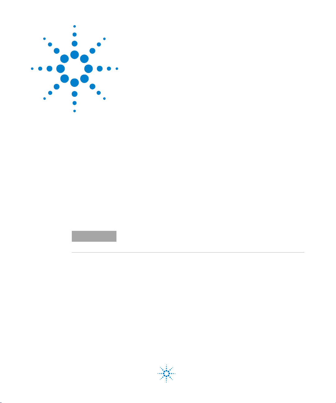
The installation dialog box
appears (see below).
Select this option
3 Select View and read the E6474A Release
Notes before installing.
4 Select Install next to the E6474A Wireless
Network Measurement Software option.
5 Follow the installation instructions Select the Cus tom I nstall option
These notes provide additional
information that may not be
covered in this guide.
Before selecting this option you
can find out more by clicking the
information button.
if you wish to install sample
default plan and demo files.
Once the installation has completed you are returned to the
installation dialog box.
Agilent E6474A User’s Guide 17
Page 18
2 Installing the Software
Install Analysis Reporter software
The Analysis Reporter (Agilent E6474A-758) option is a
simple-to-use post-processing report tool. It quickly generates
network performance overview and detailed network analysis
reports.
Follow these steps.
Do This Notes
1 Insert the Agilent E6474A CD. This CD contains the required
software device drivers.
2 Your system may have autostart or go to
the Start button, click Run and type D:\
setup (where D is your CD drive).
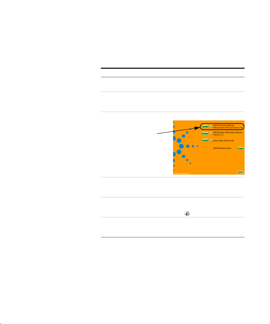
3 Select Install next to the E6474A Option
758 Analysis Reporter option.
4 Follow the installation instructions If you have a previous version of
Select this option
The installation dialog box
appears (see below).
Before selecting this option you
can find out more by clicking the
information button.
Analysis Reporter installed on
your PC your will be prompted to
over-write with the newer
version.
Once the installation has completed you are returned to the
installation dialog box.
18 Agilent E6474A User’s Guide
Page 19
Install Adobe Reader software
Installing the Software 2
NOTE
If you already have this software installed on your PC, you do not need to
install the Adobe Reader software.
All the documentation supplied with your system is also
available in PDF (Portable Document Format) for online
viewing. All these documents can be viewed once the main
E6474A software has been installed.
To v ie w do cu m ent s:
1 Start the E6474A software.
2 Select Help > Library.
To read the supplied documents you need to have the Adobe
Reader software installed on your PC.
To install the Adobe Reader software.
Do This Notes
1 Insert the Agilent E6474A CD. This CD contains the required
software device drivers.
2 Your system may have autostart or go to
the Start button, click Run and type D:\
setup (where D is your CD drive).
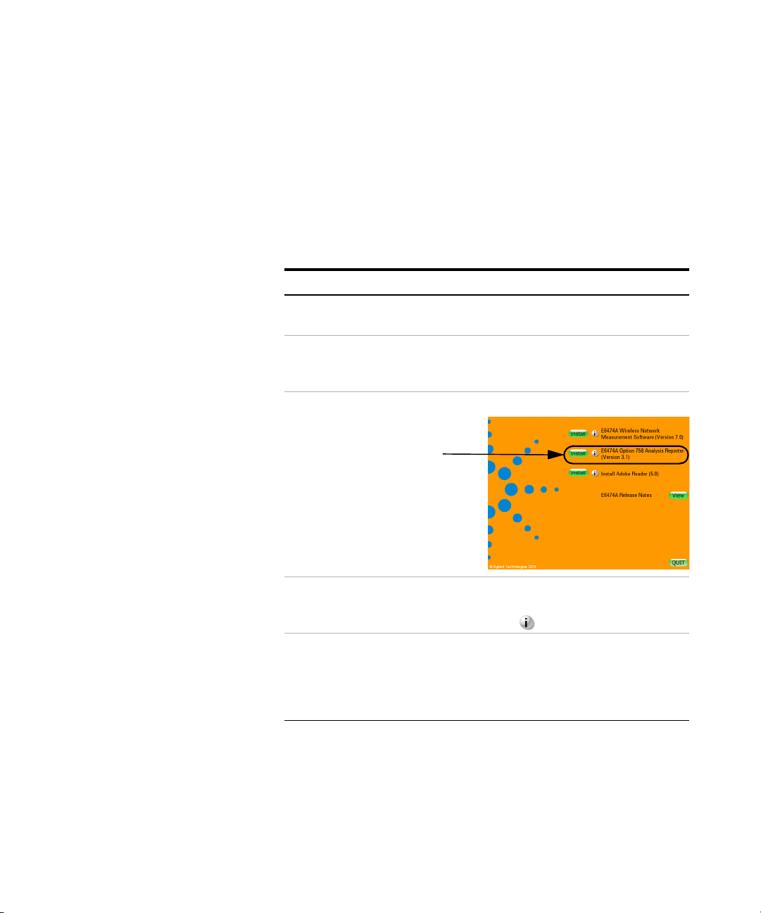
Select this option
Agilent E6474A User’s Guide 19
The installation dialog box
appears (see below).
Page 20

2 Installing the Software
Do This Notes
3 Select Install next to the Adobe Reader
software option.
4 Follow the installation instructions You may need to restart your PC
Before selecting this option you
can find out more by clicking the
information button.
once the installation has
completed.
Once the installation has completed you are returned to the
installation dialog box.
If you have installed the options you require, select
(Quit) to close the installation screen.
20 Agilent E6474A User’s Guide
Page 21

Uninstalling the Walkabout or VoicePrint software
It is recommended that you uninstall existing Walkabout, or
VoicePrint software prior to installing E6474A software.
Uninstalling Existing Software
Follow these steps:
Do this Notes
1 Select Start button.
2 Select Settings > Control Panel.
3 Double-click Add/Remove Programs.
4 Select Walkabout or VoicePrint.
5 Click Yes to begin the uninstallation process.
6 When the uninstallation is completed, restart your
PC.
Installing the Software 2
Agilent E6474A User’s Guide 21
Page 22
2 Installing the Software
Verifying your software installation
Once you have installed the E6474A software you can verify the
installation using the following methods.
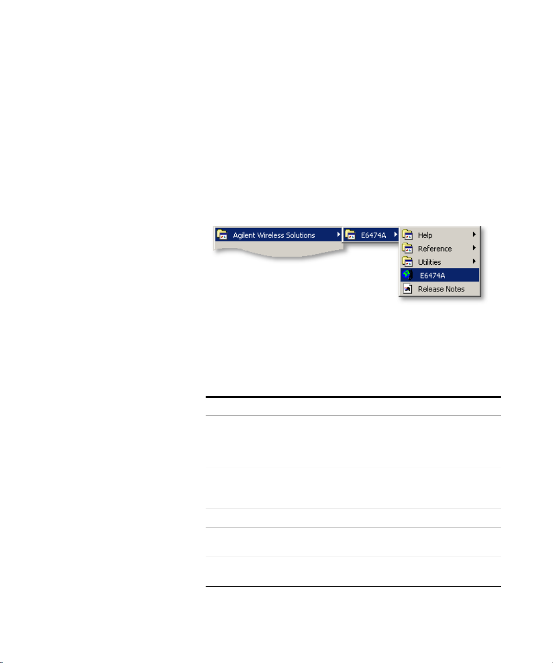
An option will appear in your program listing.
Select Start > Programs > Agilent Wireless Solutions >E6474A
and you should see a new program group and items added to
your program listing. Refer to Figure 1.
Figure 1 Menu item options after installation
Start the software and check you license options
Do the following.
Do this Notes
1 Attach your USB license dongle to
your PC.
2 Select Start > Programs >
Agilent Wireless Solutions >
E6474A > E6474A.
3 Select Help > About E6474A... The About E6474A dialog box appears.
4 Confirm you have the version of
software you ordered.
5 Select the License Info button The License Information dialog box
This also applies to parallel license
dongles.
Your PC should automatically detect the
USB license dongle.
The E6474A software starts.
appears.
22 Agilent E6474A User’s Guide
Page 23

Do this Notes
Installing the Software 2
6 Confirm the license descriptions
match your ordered license
options.
If no license descriptions appear in this
dialog box, check that you have properly
connected a valid license dongle.
Ordered license options can provide a range of measurement
features. When you view the license descriptions, you will see
more features listed than the options you ordered.
If you are having problems with installing the software or
verifying its operation, refer to “Get Assistance, if You Need
It" on page 101.
Agilent E6474A User’s Guide 23
Page 24

2 Installing the Software
24 Agilent E6474A User’s Guide
Page 25

Agilent E6474A
User’s Guide
3
Set Up Your System
Overview 25
E6473B High Speed Direct Connect Hub 26
Phones 36
Agilent Digital Receivers 40
GPS and GPS/DR 47
Batteries 55
Indoor Setup 58
License Manager 72
Overview
NOTE
This chapter explains how to configure and set up each type of
hardware that forms part of your E6474A system.
Do not connect hardware until you installed the Agilent E6474A software.
Refer to “Installing the Software" on page 15.
Agilent Technologies
25
Page 26

3 Set Up Your System
E6473B High Speed Direct Connect Hub
The E6473B High Speed Direct Connect Hub expands the serial
communication capabilities of your computer. The computer
and hub communicate via the Universal Serial Bus (USB). The
hub converts the USB to six serial (COM) ports, which are in
turn connected to the devices.
Up to two phones and two Agilent digital receivers can be
connected to the hub. It also provides power to all devices,
phone battery charging, phone audio monitoring, and a serial
port for a GPS receiver or GPS/DR navigator.
In this section you can find:
To do this Refer to
How to connect your E6473B hub. page 27
How to power your E6473B hub. page 28
How to connect a License key dongle. page 31
How to connect other devices to the E6473B hub. page 31
How to connect two E6473B hubs together page 32
Verifying E6473B hub installation page 32
NOTE
26 Agilent E6474A User’s Guide
Windows 2000 and XP
Window 2000 and Window XP requires that anyone installing hardware
drivers must have System Administrator rights. If you do not have System
Administrator rights for the computer on which the E6473B drivers need to
be installed, contact your site’s IT Support for assistance.
Page 27
How to connect the E6473B hub
Set Up Your System 3
NOTE
Do not connect the E6473B High Speed Direct Connect Hub until you have
installed the E6474A software. Refer to “Install the E6474A software." on
page 17.
Follow these instructions.
Do this Notes
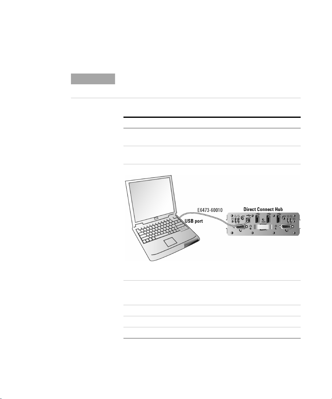
1 Connect the E6473B hub to a suitable power
source.
2 Connect the E6473B hub to the USB port of
your PC.
Refer to “How to power your
E6473B hub" on page 28.
Refer to Figure 2.
Figure 2 USB connection between the E6473B hub and your PC.
3 Follow the hardware installation wizard that
starts automatically when you connected the
E6473B hub.
4 Select ‘Search for a suitable driver’.
5 Select ‘Specify location’.
6 Follow the installation instructions.
Agilent E6474A User’s Guide 27
Page 28

3 Set Up Your System
Do this Notes
7 Select the drivers that were added to your PC
when you installed the E6474A software.
These can be found in:
C:\Program Files\Agilent Technologies\
Shared\Drivers\Edgeport\E6473B
8 Accept all the installation options listed by the
installation wizard.
9 The installation process is repeated for each
added port.
10 Restart your PC.
Do not use any other drivers.
Select ‘yes’ for any digital
signature dialogs.
How to power your E6473B hub
The E6473B hub can be powered from any of these sources.
Powering the E6473B hub Refer to
Power from the in-vehicle lighter socket using the in-vehicle
lighter cable (E6473-90004) (option 015).
Power from the in-vehicle chassis (E6473-60224) connected
directly to the vehicle ignition system (option 021).
Power from a battery (E6473-60008) connection using the
in-building chassis (E6473-60225) (option 022).
page 28
page 29
page 30
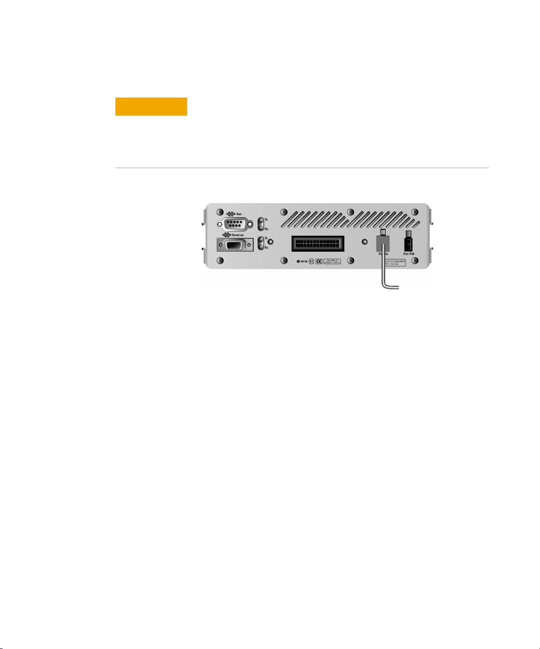
Power the E6473B hub from the in-vehicle lighter socket
The E6473B hub (option 015) is supplied with a lighter power
cable. The E6473B hub is connected directly to the in-vehicle
lighter socket. Refer to Figure 3 on page 29.
28 Agilent E6474A User’s Guide
Page 29
Set Up Your System 3
CAUTION
Using the in-vehicle lighter socket to power the E6473B hub may cause
problems if more than one device is attached to the hub.
It is recommended that the E6473B hub is powered using the in-vehicle
ignition system. Refer to “Permanent In-Vehicle Hardware Installation" on
page 171.
to vehicle lighter
socket (E6473-60004)
Figure 3 Power E6473B hub directly from lighter socket
Power the E6473B hub using the in-vehicle chassis
The E6473B in-vehicle chassis has a built-in power socket which
the E6473B hub plugs into. The chassis allows connection to
your car ignition system. Refer to “Direct Connect Hub
Installation" on page 174 for more information about connecting
the E6473B hub to your vehicle ignition system. Figure 4 below
shows the E6473B hub fitted into the in-vehicle chassis (shown
with the E6473B GPS/DR unit) and the in-vehicle power
connections.
Agilent E6474A User’s Guide 29
Page 30
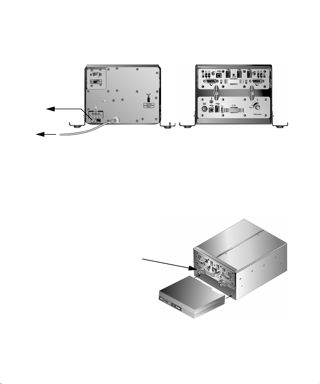
3 Set Up Your System
Power to vehicle
ignition system
Power ground cable to vehicle
Rear view of hub
Figure 4 E6473B hub inside in-vehicle chassis
Front view of hub
Power the E6473B hub from a battery
The E6473B hub can be used for indoor measurement systems
and is powered using an Agilent battery (E6473-60008). Refer to
Figure 5.
Locking knobs:
After inserting the battery
and hub, the knobs should
be turned vertical and the
screws tightened to lock
in place.
Battery
Figure 5 Inserting the battery into the chassis with the E6473B hub.
30 Agilent E6474A User’s Guide
Page 31

Set Up Your System 3
Refer to “Batteries" on page 55 for more information about the
battery and how to use it.
How to connect a license key dongle to the E6473B hub
Once the E6473B hub has been configured and an adequate
power supply has been provided, it is possible to attach devices,
such as the USB license dongle.
The USB license dongle can be plugged into any of the three
USB ports
on the front of the hub. Refer to Figure 6.
Attach USB License Dongle
Figure 6 Fit the USB dongle to any of three USB ports.
How to connect other devices to the E6473B hub
The E6473B hub is part of the E6474A measurement system.
Other parts of the system that the hub supports, include:
System component Refer to
Phones page 36
Agilent digital receivers page 40
GPS and GPS/DR page 47
Batteries page 55
Indoor setup page 58
Agilent E6474A User’s Guide 31
Page 32

3 Set Up Your System
Connecting two direct connect hub systems
To find out more about connecting these devices to the E6473B
hub and how the hub is configured, refer to the relevant section
in this chapter.
If your system includes two Direct Connect Hub units, connect
them together as follows:
Do this
1 Connect the USB cable (E6473-60005) to the (USB
Downstream) port on the front panel of the Direct Connect
Hub connected to the computer.
2 Connect the opposite end of the cable to the (USB
Upstream) port on the front panel of the second Direct
Connect Hub.
3 If programmed, insert the software license key into the
(USB Downstream) port on the front panel of any
available USB Downstream. Otherwise, plug the DB25 key
into the parallel port of the computer
Notes
Direct connect hub connections
CAUTION
To prevent damage to the direct connect hub or phone, always power
the direct connect hub off before connecting or disconnecting a phone.
Verifying E6473B hub installation
To verify driver installation and that your PC can see the
E6473B hub you should use the configuration utility and device
manager to confirm port identification.
Once the E6473B hub drivers have been installed, a COM port
utility is added to your PC. With this utility you can see what
COM ports have been assigned to which part of the hub and lets
you change COM port labelling.
32 Agilent E6474A User’s Guide
Page 33

Set Up Your System 3
Verifying installation using the Configuration Utility
To verify the driver installation:
Do this
1 Connect and switch on the E6473B hub.
2 Select Start > Programs > Agilent Technologies >
Configuration Utility.
3 Select the General tab.
4 Expand the device tree so that you can see all six ports. Refer to Figure 7.
Notes
Figure 7 Configuration Utility
Test the ports using the Test Ports button:
NOTE
This test uses an internal loopback to test the ports. Devices that generate
data without being polled (for example a GPS receiver or certain phones)
can cause this test to fail. You must unplug all devices before testing the
ports.
Agilent E6474A User’s Guide 33
Page 34

3 Set Up Your System
1 Select the USB port to test.
2 Select the Test Ports button.
3 Select the ports to test.
4 Enable Use Digital Loopback option.
5 Select Begin Test.
Once the test is completed and successful (refer to Figure 8 on
page 34), the selected ports are flagged as Passed. If the ports
Fail, check the power connections and driver installation using
the Device Manager.
Figure 8 Confidence Test dialog box
34 Agilent E6474A User’s Guide
Page 35

Set Up Your System 3
Verifying Installation using the Device Manager
To verify the driver installation:
1 Connect and switch on the E6473B hub.
2 Select Start > Settings > Control Panel.
3 Select System.
4 Select the Hardware tab.
5 Select the Device Manager button.
6 Expand the device tree to see the active ports. Refer to
Figure 9 on page 35.
Figure 9 Device Manager showing E6473B ports
Agilent E6474A User’s Guide 35
Page 36

3 Set Up Your System
Phones
Overview
The Agilent E6474A system supports a wide range of phones
and data communication devices. A list of the currently
supported phones can be found in the Library. To access this
list open the E6474A software and select Help > Library or
Start > Programs > Agilent Wireless Solutions > E6474A >
Reference > Library.
Phones can be connected to your system using the following
methods:
Phone connection using
Direct serial port page 36
PCMCIA (PC Card) page 37
NOTE
E6473B hub page 37
USB port page 39
Phone battery charging and audio monitoring are not supported with direct
connect phones.
Refer to
Phone connection using direct serial port
Depending on the type of phone you wish to connect to your
laptop. It may be possible to connect the phone directly to your
laptop serial port.
Refer to the phone manufacturers instructions before
connecting a phone.
36 Agilent E6474A User’s Guide
Page 37

Phone connection using PCMCIA (PC Card)
To extend your laptop serial port capability you can use a
dual-port serial PCMCIA (PC-card) I/O card. Refer to Figure 10
on page 37.
Refer to the PCMCIA manufacturer instructions before
installing this device.
Set Up Your System 3
Figure 10 Connecting a phone using a PCMCIA card
Phone connection using the E6473B hub
The E6473B hub provides two ports for connecting phones.
Each port provides a voice and data capability while charging
the attached phone.
NOTE
Agilent E6474A User’s Guide 37
To use the two phone ports on the front of the E6473B hub you have to use
a special cable. Refer to the list of supported phones to see if a cable
exists for your phone.
To access this list open the E6474A software and select Help > Library.
Page 38

3 Set Up Your System
Figure 11 on page 38 shows the two phone connection ports.
These ports are labelled
Port B in Figure 11 on page 38.
and . Refer to Port A and
A
Figure 11 COM port allocation for phone ports
When certain types of phones are connected to the E6473B hub
their sound output is disabled. To hear the attached phone
sound output, you can use headset sockets marked
Refer to the online help in the E6474A software for information
on directing phone sound through your laptop. Refer to
Figure 12 on page 38.
B
C D
or .
Headsets
Figure 12 Connecting two phones to the E6473B hub
38 Agilent E6474A User’s Guide
Page 39

Phone connection using a USB port
Some phones can be connected to your system using USB
interface cables. When these types of phones are connected to
your system, your PC should automatically detect the new USB
device.
The USB drivers used by these phones may require custom
installation processes. Follow the phone manufacturers
instructions for configuring USB phone connections.
External antennas
The following phone interface kits include antenna adapters. If
your system includes one of the phone interface kits listed in
Table 1, follow these steps:
1 Connect the antenna adapter to the phone.
2 Connect the antenna extender cable (E6473-60105) to the
appropriate adapter, if necessary. (Two adapters are
included with the antenna kit). The antenna extender cable
connectors are both FME female type.
3 Connect the antenna to the extender cable.
4 Mount the antennas on the roof of the vehicle, with at least
18” (approx. 46 cm) between antennas.
Set Up Your System 3
Ta b l e 1 Adapters used in kits
Phone interface kit part
number
E6473-803 QCP 860, 1960, and 2760 E7483-60002 TNC female
E6473-830 Nokia 61xx E7484-60023 FME male
Phone antenna kit part
number
E6473-898 900/1800 MHz E6473-60101 E6473-60102
E6473-899 800/1900 MHz E6473-60101 E6473-60102
Use with phone(s) Adapter part number Adapter type
Use with frequency bands TNC male to FME male
adapter part number
FME male to FME male
Adapter part number
Agilent E6474A User’s Guide 39
Page 40

3 Set Up Your System
Agilent Digital Receivers
Overview
Agilent manufactures a range of digital RF receivers that cover
most technologies. All receivers are supplied with an internal
GPS systems. For technical details of the available receivers,
refer to “Receiver Specifications" on page 146.
Receivers can be connected and configured using the following
methods:
Receiver configuration
Connect directly to your laptop page 41
Connect to your in-vehicle E6473B hub page 42
Connect two receivers to your in-vehicle E6473B hub page 42
Connect multiple receivers page 44
NOTE
Pulse trigger the receivers page 45
For details on how to upgrade the Agilent receiver firmware, refer to
“Updating E645xx Receiver Firmware" on page 120.
Refer to
40 Agilent E6474A User’s Guide
Page 41

Connect directly to your laptop
The Agilent digital receiver can be connected directly to the
serial port of your laptop. The direct serial port connection
provides RF measurement information and GPS coordinate
results.
Refer to Figure 13 on page 41 for typical serial port connection
(this diagram does not include a GPS antenna).
Set Up Your System 3
Serial port
RF Antenna
Figure 13 Serial port connection for Agilent digital receiver
Agilent E6474A User’s Guide 41
Page 42

3 Set Up Your System
Connect to the E6473B hub
to
RF antenna
Receiver
An Agilent digital receiver can be connected to the E6473B hub
using the receiver port (marked with
the hub. The receiver cable (E6473-60006) splits into a data
cable and power cable. Refer to Figure 14.
E6473-60006
to optional GPS
) on the back of
to vehicle power
Figure 14 Data and power connection for one receiver
E6473B Hub
Connect two receivers to your in-vehicle E6473B hub
The E6473B hub provides an additional power socket for
powering a second Agilent digital receiver.
Connections for receiver 1
1 Connect the RS-232 port on the receiver 1 to the receiver
port on the hub (
2 Connect the power lead part of the E6473-60106 cable to
receiver 1 power socket.
42 Agilent E6474A User’s Guide
) using the cable E6473-60106.
Page 43

to RF antenna
Set Up Your System 3
Connections for receiver 2
1 Connect RX LOOP IN on receiver 1 to RX LOOP OUT on
receiver 2 using cable E6450-60002.
2 Connect RX LOOP OUT on receiver 1 to RX LOOP IN on
receiver 2 using cable E6450-90001.
3 Connect power on receiver 2 to Aux Out socket on the
E6473B hub using cable E6473-60091.
Refer to Figure 15 on page 43.
E6473-60106
Receiver 1
to optional GPS
to vehicle power
E6450-60002
E6450-60001
to RF antenna
Receiver 2
Figure 15 Data and power connection for two receivers
Agilent E6474A User’s Guide 43
E6473-60091
E6473B Hub
Page 44

3 Set Up Your System
Connect multiple receivers
When you configure multiple receivers, only one receiver (the
master receiver) is physically connected to the computer and is
able to supply input from the GPS. You attach an external GPS
system (unless it has internal GPS) to the master receiver only.
The other receiver(s) receive their GPS signal from the master
receiver. If other receivers contain internal GPS systems, their
GPS is ignored.
To connect multiple receivers:
1 Attach one end of a short cable to the RX LOOP IN connector
on the master receiver. Attach the other end of the short
cable to the RX LOOP OUT of the second receiver.
2 Continue to attach receivers (up to a total of four receivers)
as in step 1.
3 When all receivers are connected with short cables, connect
one end of a long cable to the RX LOOP OUT connector on the
master receiver to the RX LOOP IN on the last receiver in the
series.
4 Connect the serial port of your laptop to the RS-232 port of
the master receiver with an RS-232 cable.
5 Connect the RF antenna to the RF input of each of the
receivers.
Refer to Figure 16 on page 45.
44 Agilent E6474A User’s Guide
Page 45

Set Up Your System 3
Figure 16 Connecting more than one receiver to your laptop
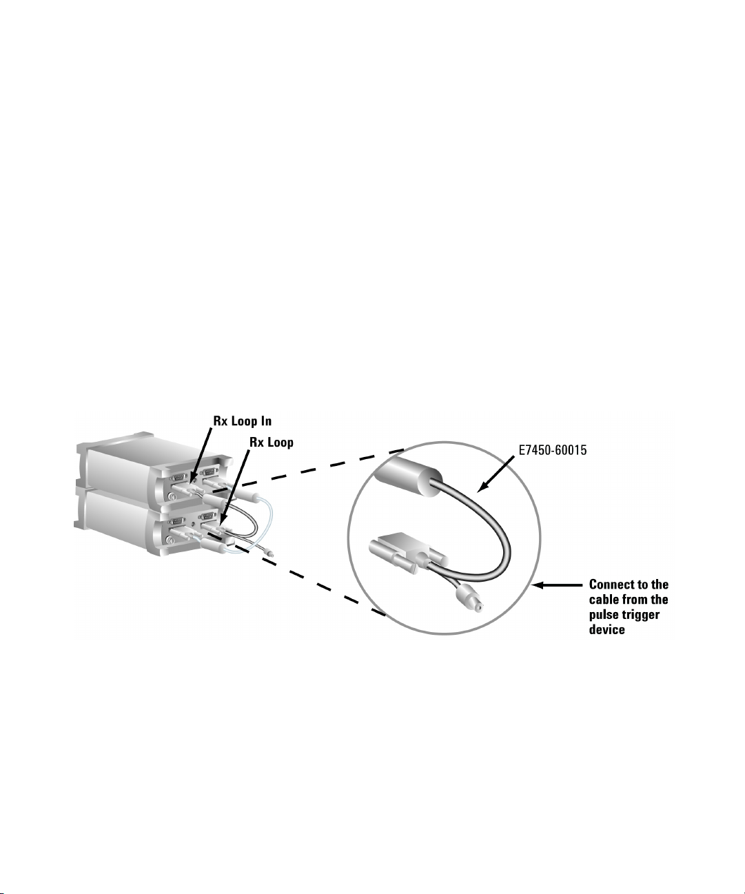
Pulse trigger the receiver
The E645xC receivers accommodate a pulse trigger device. The
triggering device requirements are:
• Cable with BNC male connector (the Agilent pulse trigger
cable input is female BNC)
• Falling-edge trigger
• TTL threshold
• 15 volt maximum pulse level
• 100 nanosecond minimum pulse width of period
Agilent E6474A User’s Guide 45
Page 46
3 Set Up Your System
• 300 microsecond minimum pulse
Follow the manufacturer’s instructions for installing the pulse
trigger device. Connections to the receiver are shown in
Figure 17.
• If you have two receivers, connect the pulse trigger cable
(E7450-60015) to the R
shown in Figure 17.
• Or, if you have one receiver, connect the pulse trigger cable to
X LOOP IN and RX LOOP OUT ports of the same receiver.
the R
• Connect the cable from the pulse trigger device to the BNC
connector of the pulse trigger cable. For software
configuration and calibration instructions, refer to the online
help. Search for “wheel pulse unit setup” to locate the
information.
X LOOP IN and RX LOOP OUT ports as
Figure 17 Connecting the pulse trigger cable
46 Agilent E6474A User’s Guide
Page 47

GPS and GPS/DR
Overview
Set Up Your System 3
To provide accurate measurement analysis and signal
synchronization, the Agilent E6474A system provides
comprehensive methods of support for Global Positioning
Systems (GPS).
The Agilent E6474A system obtains its GPS signal from a variety
of sources. GPS systems can be connected and configured using
the following methods:
GPS and GPS/DR configuration
Agilent digital receiver internal GPS page 47
Agilent digital receiver external GPS page 47
External GPS using the E6473B hub page 51
Agilent GPS/DR navigator page 51
Indoor positioning page 54
Agilent digital receiver internal GPS
All Agilent digital receivers are supplied with an internal GPS
system. When an Agilent digital receiver is connected to your
system, this GPS device is automatically detected. GPS signals
are passed to your system through the serial connection.
Agilent digital receiver external GPS
The following examples show a complete system with various
external GPS systems attached through an Agilent digital
receiver. These examples show the external GPS and receiver
connected to a PC, however the same connection can be made to
the AUX port on the E6473B hub. Refer to Figure 18 on page 48.
Refer to
Agilent E6474A User’s Guide 47
Page 48

3 Set Up Your System
Example 1 - Using the internal GPS with a differential GPS antenna.
Figure 18 Internal GPS with optional differential GPS
Example 2 - Using Placer GPS 455
In this example the external GPS unit is connected using an
adapter box. The adapter box is connected to the GPS RS-232
port on the receiver.
Refer to Figure 19 on page 49.
The adapter box is connected to the MDT/RTCM and Digital IO
ports.
48 Agilent E6474A User’s Guide
Page 49

Set Up Your System 3
Figure 19 External GPS - Placer 455
Example 3 - Placer 455 with differential GPS
Refer to Figure 20 on page 50.
1 Connect the RTCM port of the Trimble-supplied
communications cable to the differential GPS receiver, using
the RS-232 cable included with the system. Connect the
remaining port of the Trimble-supplied communications
cable to the MDT/RTCM port of the Trimble Placer GPS 455
unit.
2 Connect the digital port of the adapter box to the Digital IO
port of the Trimble Placer GPS 455 unit, using the RS-232
cable.
3 Connect the MDT/RTCM port of the adapter box to the MDT
port of the Trimble-supplied communications “T” cable,
connected to the Differential, using the RS-232 cable.
Agilent E6474A User’s Guide 49
Page 50

3 Set Up Your System
4 Connect the GPS antenna to the GPS ANT port of the Trimble
Placer GPS 455 unit. Agilent Technologies recommends that
a “bulkhead mount” GPS antenna be used whenever possible
for improved performance.
Figure 20 Placer 455 GPS with differential GPS
50 Agilent E6474A User’s Guide
Page 51
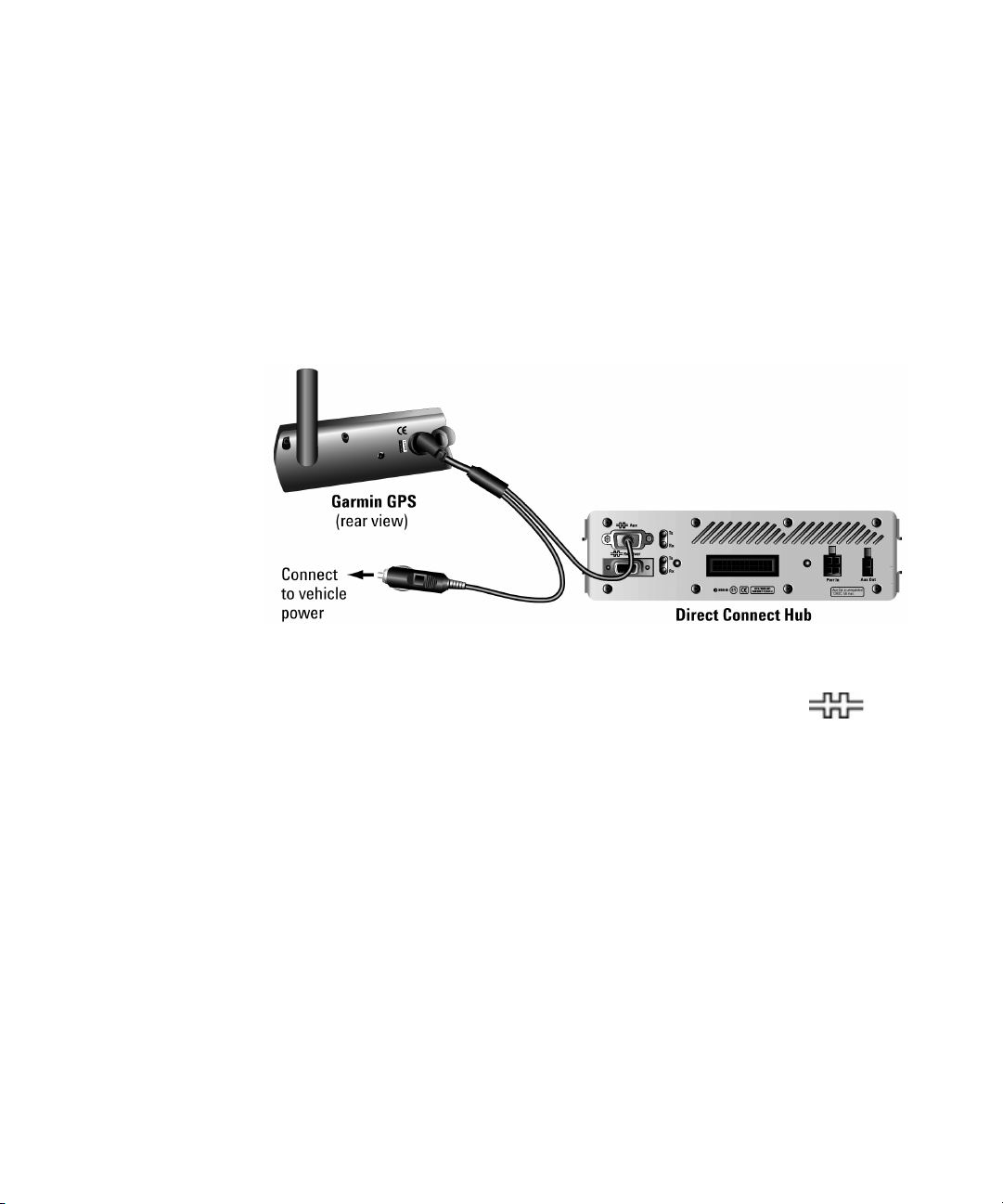
External GPS using the E6473B hub
Other types of external GPS systems can be connected to the
E6473B hub. This example shows the Garmin II Plus GPS
Receiver connected to the E6473B hub.
1 Connect the interface cable to the GPS receiver. See
Figure 21.
Set Up Your System 3
Figure 21 Connect the GPS to the AUX connector
2 Connect the D-shell connector of the cable to the AUX
port on the rear panel of the Direct Connect Hub. See
Figure 21.
3 Connect the power plug to the lighter socket.
Agilent GPS/DR navigator
The Agilent GPS/DR navigation option (Option 30 and 31) is a
GPS Dead-Reckoning unit that can be connected to your system
using one of the following three methods:
Agilent E6474A User’s Guide 51
Page 52

3 Set Up Your System
Method 1 - In-vehicle chassis
Connect using the in-vehicle chassis. Data and GPS information
is passed to your PC through the E6473B hub. See Figure 22 on
page 52.
Figure 22 GPS/DR system fitted into the in-vehicle chassis (shown
with the E6473B hub)
Method 2 - USB connection
If the GPS/DR unit can not be fitted to the in-vehicle chassis it is
possible to use the downstream USB port. Power is provided
from the power socket at the back of the unit (power cable
E6473-60004).
Method 3 - Serial connection
You can use the serial port on the back of the GPS/DR unit
(refer to Figure 23). Connect this port to the serial port on your
The GPS/DR serial port overrides the USB port.
PC.
Figure 23 Serial port on GPS/DR unit
52 Agilent E6474A User’s Guide
Page 53

Gyro positioning
Set Up Your System 3
To avoid inaccuracies in dead reckoning, the Gyro in the Agilent
Direct Connect GPS/DR must be positioned so that it is within
10 degrees of vertical or horizontal. The Gyro must be set to
indicate the Up position on the unit as follows:
1 Position the unit either horizontally or on its right edge
(vertically).
2 Turn the Gyro Position knob counter-clockwise to loosen it.
3 Slide the pin so that it indicates the applicable Up position.
4 Turn the Gyro Position knob clockwise to tighten it.
Figure 24 Setting the Gyro pin. If the unit is set on its right side, the pin is set at the alternate position.
Connecting the Speed Pulse
CAUTION
The dead reckoning system is comprised of the Gyro and the Speed
Pulse (odometer) connection. The connection of the Speed Pulse cable
is vehicle-specific and should be performed by persons trained to do
such installations.
When connecting the Speed Pulse cable, the following wiring
scheme is used:
Agilent E6474A User’s Guide 53
Page 54

3 Set Up Your System
Indoor positioning
Color Connection
Red Speed Pulse (odometer)
Black Ground
White Backup (seldom used; not
necessary for proper
operation)
Shield
The Agilent E6474A system supports indoor measurements.
Mapping and recording data for indoor environments requires
the following items:
• Detailed floor and building plan (BMP format).
• Pen tablet laptop (preferred).
• (optional) 1 PPS signal for CDMA measurements
synchronization.
Full details on how to perform indoor measurements and
configure the indoor positioning and tracking, refer to the
online help and quick basics tutorial.
54 Agilent E6474A User’s Guide
Page 55

Batteries
Set Up Your System 3
Checking the remaining charge
Press the test button shown in Figure 25 to check the remaining
charge capacity. The battery charge level can be checked while
the Direct Connect Hub power switch is on or off; however
checking it with the power on may provide a more accurate
indication.
LEDs Lit Capacity Remaining
5 81% to 100%
4 61% to 80%
3 41% to 60%
2 21% to 40%
1 1% to 20%
Figure 25 Lithium-ion battery
Charging the battery
The battery (E6473-60008) can be charged within the carry bag.
Disconnect the charger (E6473-60009) from the battery before
checking the charge. The battery is fully charged when all five
LEDs are lit.
Agilent E6474A User’s Guide 55
Page 56

3 Set Up Your System
WARNING
Never charge the battery when the E6473B Hub is powered on. Use
only the approved charger, part no. E6473-60009.
1 Connect the battery charger cable to the battery.
2 Plug the battery charger’s AC power cord into a 100-240V AC
50-60 Hz power source.
3 Allow approximately three hours to fully charge the battery.
Safe handling and disposal
For the safe use of lithium-ion batteries, always follow the
instructions provided below. Improper handling of lithium-ion
batteries may result in injury or damage from electrolyte
leakage, heating, ignition, or explosion. Batteries must be
recycled or disposed of properly.
56 Agilent E6474A User’s Guide
Page 57

Set Up Your System 3
WARNING
Always use the battery charger provided with the battery.
Never heat or incinerate the battery.
Never impact, pierce, or crush the battery.
Never disassemble or modify the battery. The battery contains a
circuit designed to enhance safety. Damaging this circuit may cause
overheating, fire or bursting.
Never charge a battery under high temperature conditions, such as
near a fire or in the direct sunlight. If the ambient temperature is too
high, the protection circuit may be actuated, preventing further
charging, or damage.
Never short-circuit the battery by connecting the positive and
negative terminals with a metal material.
Do not store or carry the battery where it could come into contact
with metal objects such as a key chain or necklace.
Never allow the battery to get wet or be immersed in water.
Do not place the battery in a microwave oven or high-pressure
container.
Stop charging if the battery is not charged after the prescribed
charge time.
If leakage of the electrolyte occurs, or if there is an offensive odor,
keep the battery away from any source of fire or spark.
If you become aware of any abnormal phenomena, such as odor,
discoloration, or deformation, during use, while charging, or when
storing the battery, remove the battery from the device or charger
and stop using.
In the event the electrolyte comes into contact with the eyes, flush
thoroughly with clean water, without rubbing. Consult with a
physician immediately.
Agilent E6474A User’s Guide 57
Page 58

3 Set Up Your System
Indoor Setup
Overview
Portable system cable connections
This section contains instructions for setting up a portable or
indoor system. A single lithium-ion battery powers the portable
system. Always charge all batteries before beginning a survey.
Cable connections to the rear panels should be made before the
E6473B hub and the battery pack are loaded into the carry bag.
Cable connections to the front panels can be made after the
components are inserted into the carry bag. If the system is not
equipped with a receiver, no cable connections are made to the
rear panel of the E6473B hub.
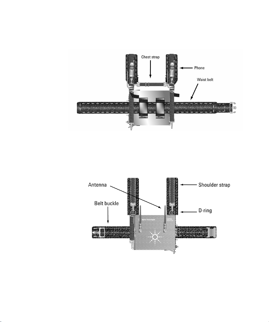
Carry pack final assembly
1 Route the antenna, phone, and computer cables through the
openings provided.
2 Close all open panels.
3 Attach the clip-on receiver antenna to the pocket of pack. See
Figure 28 on page 60 for an example.
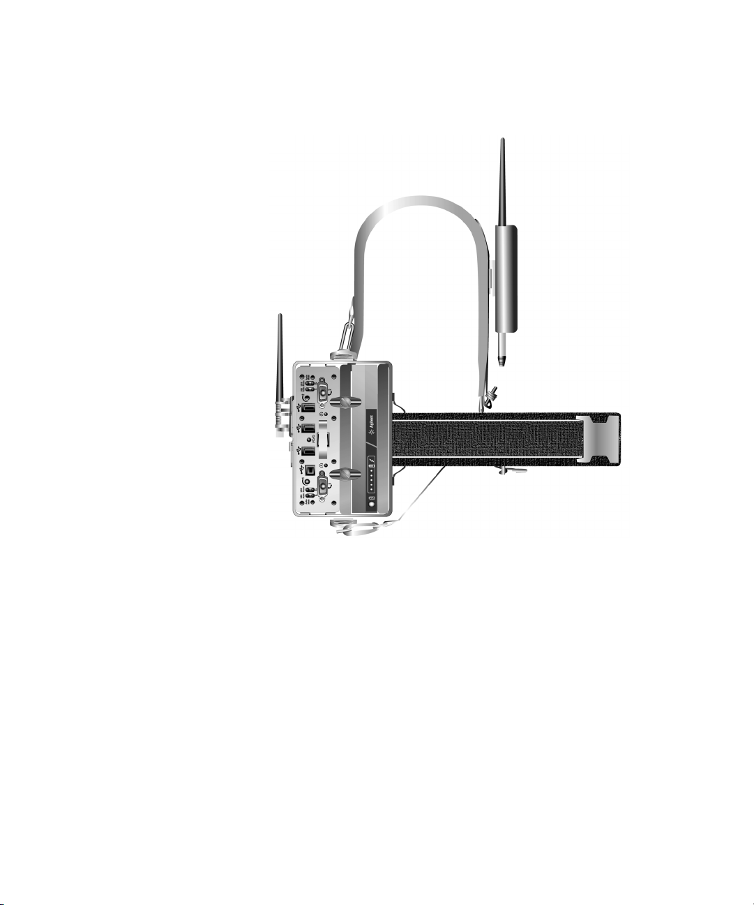
Using carry pack assembly with the shoulder strap
See Figure 26 on page 59 for an example.
1 Attach the shoulder strap to the D-rings.
2 Slip the shoulder strap around your neck.
58 Agilent E6474A User’s Guide
Page 59

Set Up Your System 3
Figure 26 Side view of the carry pack showing the shoulder strap
Using the carry pack as a backpack
1 Adjust the waist belt for a snug fit around your waist, then
remove it.
2 Feed the waist belt through the belt loops of the pack, as
shown in Figure 27 on page 60. The black mesh should be on
the outside.
Agilent E6474A User’s Guide 59
Page 60
3 Set Up Your System
Figure 27 Carry pack inside view
3 Connect the two shoulder straps to the D-rings of the pack as
shown in Figure 28.
Figure 28 Carry pack outside view
4 Mount the pack to your body, then connect the buckle of the
waist strap. See Figure 29 on page 61.
60 Agilent E6474A User’s Guide
Page 61
Set Up Your System 3
Figure 29 Carry pack side view
5 Adjust the shoulder straps.
6 Connect the chest strap to the D-rings of the shoulder straps
as shown in Figure 27 on page 60.
7 Adjust all straps for a comfortable fit.
Portable digital receiver system
This section describes the cable connections for a system
equipped with one Agilent digital receiver. This configuration is
housed in a single receiver backpack hub kit,
Agilent E6474A User’s Guide 61
Page 62

3 Set Up Your System
E6473B option 023. The carry bag contains a bracket that
secures the Direct Connect Hub and the battery, and provides
the power connection between them.
NOTE
Refer to Appendix C, “System Information", for antenna and phone
interface cable part numbers.
Chassis and backpack assembly
Use the straps provided to secure all components within the
single receiver backpack.
1 Insert the battery into the chassis, and then push until it
locks in place, as shown in Figure 5 on page 30.
NOTE
The battery is keyed, and can only be properly inserted into the chassis
when the connectors are aligned.
2 Align the tabs of the Direct Connect Hub with the slots in the
chassis, then attach it to the chassis by pushing it rearward
until it locks in place.
3 Secure the chassis assembly within the right side of the
backpack.
4 Secure the Agilent digital receiver within the left side of the
backpack.
62 Agilent E6474A User’s Guide
Page 63
Set Up Your System 3
Final assembly
1 Route the USB, antenna, and phone cables through the
openings provided. See Figure 30.
Phone Pouch
Receiver
Figure 30 Single receiver backpack (right side view)
2 Close all open panels.
3 Attach the clip-on receiver antenna to the antenna loop of
the pack.
4 Attach the shoulder strap to the D-rings of the pack. See
Figure 31.
Antenna Loop
Direct connect hub
Battery
Side Panels
Agilent E6474A User’s Guide 63
Page 64

3 Set Up Your System
Battery Connector
Receiver Connector Panel
D-ring for strap
Figure 31 Single receiver backpack (left side view)
Using the single-receiver backpack
1 Adjust the waist belt for a snug fit around your waist, then
remove it.
2 Feed the waist belt through the belt loops of the pack. The
black mesh should be on the outside.
3 Connect the two shoulder straps to the D-rings of the pack.
4 Mount the pack to your body, then connect the buckle of the
waist strap.
5 Adjust the shoulder straps.
6 Connect the chest strap to the D-rings of the shoulder straps.
7 Adjust all straps for a comfortable fit.
Portable dual E645xx receiver system
This section describes the cable connections for a system
equipped with two receivers. This configuration is housed in the
dual receiver back pack hub kit, E6473B option 024. The
backpack contains a removable mounting platform to which the
receivers and hub are attached.
Belt loop
D-ring for strap
64 Agilent E6474A User’s Guide
Page 65

Set Up Your System 3
The dual receiver backpack hub kit also supports a two-direct
connect hub (no receivers) configuration. To achieve this
configuration, you must purchase two Agilent hubs (E6473B
option 015), one dual receiver backpack hub kit (E6473B-024),
and one carry pack hub kit (E6473B option 022).
The carry pack hub kit is required for the portable chassis and
the battery kit, which would be used for the second direct
connect hub. Please note that the carry pack, itself, can be
strapped into the backpack.
NOTE
NOTE
Please refer to Appendix C, “System Information", for antenna and phone
interface cable part numbers.
1 Rotate the locking knobs horizontally to allow devices to
slide into the slots of the chassis.
2 Insert the battery into the bottom slot of the chassis.
3 Rotate the locking knobs to a vertical position, and tighten
the screws.
The battery is keyed, and can only be properly inserted into the chassis
when the connectors are aligned.
Cable routing within the backpack
Refer to Figure 32 for cable routing details. Refer to “System
Information" on page 141, for antenna, phone, and headset
cable part numbers.
1 Route the receiver and GPS antenna cables through the two
openings in the cover.
2 Route the phone cables through the appropriate opening,
depending on where the phones will be attached.
3 Route the USB cable (E6473-60005) and headset cables
through the top opening.
Agilent E6474A User’s Guide 65
Page 66

3 Set Up Your System
Figure 32 Inside the backpack
Cable routing through the shoulder straps
Refer to Figure 33 for a cable routing example.
1 Route the USB cable (E6473-60005) through either shoulder
strap.
2 If the phones will be attached to the shoulder straps, route
the phone interface cables through either shoulder strap.
66 Agilent E6474A User’s Guide
Page 67

Set Up Your System 3
Figure 33 Routing cables through the shoulder straps
Receiver and hub mounting
Refer to Figure 34 on page 68 for receiver and Direct Connect
Hub mounting positions. Use the straps provided to secure the
components to the platform.
1 Remove the inner component platform from the backpack.
2 Attach the receivers to the platform.
3 Attach the hub, battery and chassis assembly to the platform.
Agilent E6474A User’s Guide 67
Page 68

3 Set Up Your System
Figure 34 Two receivers and Direct Connect Hub mounted to the platform
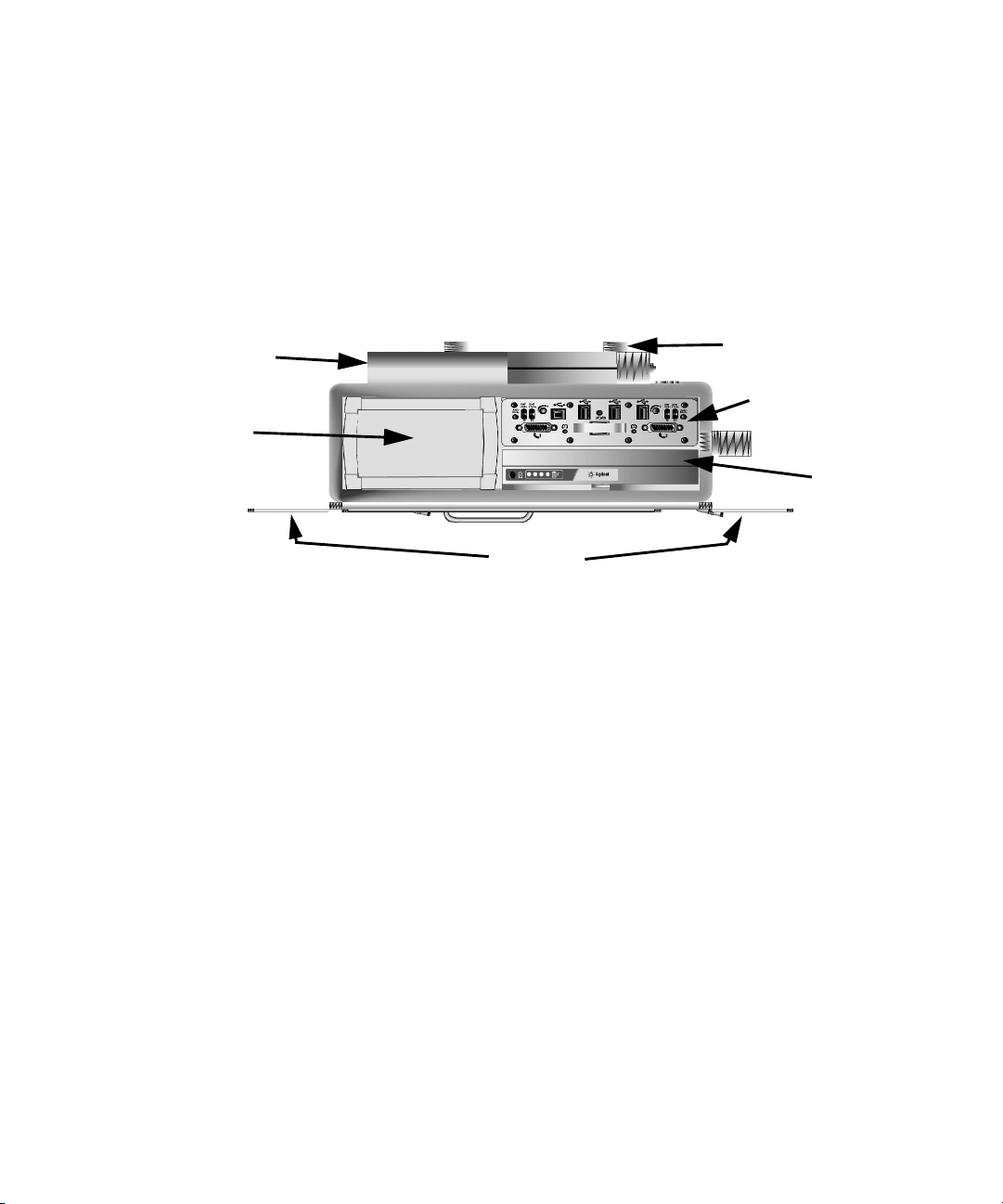
Cable connections to the E6473B hub
1 Connect the receiver data/power cable (E6473-60106) to the
2 Connect the second receiver power cable (E6473-60107) to
AUX PWR OUT connector.
the
3 If programmed, insert the software license key into the
(USB Downstream) port on the front panel. Otherwise, plug
the DB25 key into the parallel port of the computer.
4 Connect the USB cable (E6473-60005) to the (USB
Upstream) port on the front panel.
port on the rear panel.
Cable connections to the receiver
1 Connect the D-shell connector end of the receiver
data/power cable (E6473-60106) to the RS-232 port of
Receiver 1.
2 Connect the power plug of the receiver data/power cable to
the 9-34 VDC connector of Receiver 1.
3 Connect the power plug of the second receiver power cable
(E6473-60107) to the 9-34 VDC connector of Receiver 2.
68 Agilent E6474A User’s Guide
Page 69

Set Up Your System 3
4 Connect the short RX Loop cable (E7450-60001) to the RX
LOOP IN port of Receiver 1.
5 Connect the opposite end of the cable to the RX LOOP OUT port
of Receiver 2.
6 Connect the long RX Loop cable (E7450-60002) to the RX LOOP
IN port of Receiver 2.
7 Connect the opposite end of the cable to the RX LOOP OUT port
of Receiver 1.
8 Connect the receiver antennas to the RF INPUT connectors of
the receivers.
9 If equipped, connect the GPS antennas to the GPS ANTENNA
connectors of the receivers.
Dual receiver backpack final assembly
1 Place the component platform inside the backpack, as shown
in Figure 34 on page 68. It attaches to the backpack with
Velcro fasteners.
2 Connect one phone interface cable to the (Phone 1)
port of the Direct Connect Hub.
3 Connect the second phone interface cable to the
(Phone 2) port of the Direct Connect Hub.
4 Connect the headset cables (E6473-60017) to the connectors
of the Direct Connect Hub.
5 Attach the clip-on receiver antennas to the antenna loops on
the sides of the backpack. See Figure 35.
Agilent E6474A User’s Guide 69
Page 70

3 Set Up Your System
Figure 35 Backpack exterior features
6 Close all zips.
CAUTION
To prevent damage to the Direct Connect Hub or phone, always power
the Direct Connect Hub off before connecting or disconnecting a
phone.
7 With the Direct Connect Hub powered off, connect each
phone to its interface cable.
8 Attach the phones to the shoulder straps, antenna loops on
the side of the backpack, or in the phone pouches.
9 Connect the free end of the USB cable to the USB port of the
computer.
70 Agilent E6474A User’s Guide
Page 71

Set Up Your System 3
Adjusting the backpack harness
1 Loosen all straps and place the pack on your back as shown
in Figure 36.
Figure 36 Tightening the shoulder straps on the backpack
2 Fasten the waist belt and tighten it so that it rests on your
hips. The waist belt should always remain on your hips, even
after the harness is adjusted.
3 Tighten up the shoulder straps until the pack feels
comfortable. The weight of the pack should be carried on
your hips for maximum comfort. The shoulder straps help
stabilize the pack on your body.
4 Connect the chest strap. You can change the vertical position
so that the strap fits comfortably across your chest. The
sternum strap reduces shoulder fatigue and increases
mobility by pulling the shoulder straps inward.
Agilent E6474A User’s Guide 71
Page 72

3 Set Up Your System
License Manager
Introduction
Software options are enabled via software license keys (also
called “Dongles”) that are attached to either the USB or parallel
port on your computer. The software license key included with
the E6474A software contains the licenses for the software
options you have purchased. When started, the E6474A
software queries the key to determine which options to enable.
License Manager software is automatically installed when you
install the E6474A software. This software allows you to:
• Transfer licenses between keys included (for example,
between the DB25 key and USB key)
• Add software options to your license key
• Transfer licenses between keys on different computer
systems
• Transfer licensed product options between license keys
• View online help on the use of License Manager features
For more information
For complete instructions on using the License Manager, please
refer to the Welcome topic in the License Manager software’s
online help.
1 To start the License Manager, click Start > Programs >
Agilent Wireless Solutions > Utilities > License Manager.
2 Click Help > Contents to open the Welcome topic.
72 Agilent E6474A User’s Guide
Page 73

Agilent E6474A
User’s Guide
4
Use Your System
Turning the power on 74
Starting the software 77
Creating a new project 79
Identifying devices 81
Configuring devices and views 84
File types and locations 87
Configuring and creating a data project 88
Configuring and creating a WAMS project (Option 740) 92
Overview
This chapter tells you how to start configuring and using your
system.
Before you begin to collect or monitor data, you must:
Do this
Turn the power on page 74
Start the application page 77
Create a plan file page 79
Identify and enable the devices page 81
Configure the devices and the display page 84
Refer to
Agilent Technologies
73
Page 74

4 Use Your System
Turning the power on
CAUTION
Before switching on any system component, ensure that the supply
voltages are in the specified ranges. Refer to “System Information" on
page 141.
Battery charging
• For a portable system, verify that the Direct Connect Hub,
phone, and computer batteries are fully charged before
beginning a survey. Refer to “Batteries" on page 55 for more
information.
• For an in-vehicle system, verify that the phone batteries are
fully charged before beginning a survey.
E6473B high speed direct connect hub
The hub has a three-position power switch (refer to Figure 37
on page 75). It controls the power to the hub, the phones, and
the scanner or receivers. The blue LED above the power switch
will glow after the Direct Connect Hub has initialized.
• Place the switch in the left position to power the unit on. For
in-vehicle systems, if the hub is powered on and off by an
GPS/DR navigator unit, the switch should be in the left
position.
• Place the switch in the center position to power the unit off.
• For in-vehicle systems without GPS/DR navigator, placing the
switch in the right position allows the unit to power on and
off via the vehicle’s ignition switch.
NOTE
74 Agilent E6474A User’s Guide
To allow the receiver to lock onto the GPS signal, allow the system to be
powered on at least 3 minutes before starting a data collection test.
Page 75

Normal ON ON via ignition
Figure 37 E6473B hub power switch positions
Agilent direct connect GPS/DR
If the ignition sense lead of the main power cable has been
connected to a +12 volt source, the navigator powers up when
the vehicle’s ignition is switched on and the power switch is in
either the Ignition (right) or Power (left) position. (For
installation instructions, Appendix D, “Permanent In-Vehicle
Hardware Installation,” starting on page 171.)
LEDs and display during power-up
The upper front panel LED indicates Power, and the lower LED
indicates 1PPS (Pulse Per Second). The information shown on
these two LEDs comes from the GPS Receiver. One use of the
1PPS would be to indicate that the GPS receiver is active. 1PPS
is also available at pin 9 of the rear panel RS-232 DB9 connector
and is enabled by software.
Use Your System 4
OFF
The Agilent direct connect GPS/DR status LCD displays
power-up and navigation status messages. The front panel LEDs
indicate CPU status, speed pulse status, and serial port activity.
Determining GPS receiver status
You can determine whether the GPS Receiver is ready to
navigate by using the E6474A software as follows:
1 Start the E6474A software, and select Tools > Navigation to
display the Navigation dialog box.
2 Click the Live Mode button.
3 When the GPS Navigator is ready to track, the Satellites box
shows the number of satellites tracked, and the Navigation
Agilent E6474A User’s Guide 75
Page 76

4 Use Your System
display shows either 2D or 3D, with the GPS Status
displaying “Tracking.” Both speed and direction are also
displayed. If the Nav Mode shows 3D, the altitude readings in
the display are also valid.
Before starting a data collection test, allow three minutes for
the unit to acquire GPS position data. During a data collection
test, navigation data is also combined and collected.
Calibration of dead reckoning
The Dead Reckoning calibration system is virtually
self-calibrating and requires minimal user intervention. Once
the Agilent direct connect GPS/DR is properly connected and
the unit is powered on for the first time, it is not yet calibrated
and operates as a normal GPS receiver.
Once navigation begins using GPS signals, the receiver
automatically calibrates the sensors. During this calibration
process, the vehicle must be maneuvered in a specific manner
in order for the unit to calibrate, as follows:
1 Stop the vehicle for at least three seconds in order to
determine the gyro bias.
2 Drive in a straight line for a distance of approximately one
kilometer (0.62 mile).
3 Turn the vehicle, and proceed in another straight line for
approximately one kilometer (0.62 mile).
The period of time and distance traveled that are required for
the system to calibrate the Dead Reckoning sensors vary
depending on the GPS signal quality and receiver temperature
stability. The calibration continuously refines itself as you
drive.
NOTE
76 Agilent E6474A User’s Guide
Toshiba JCDMA phones have special power-up procedures. Refer to
“Toshiba phone power-up issues" on page 104 for more information.
Page 77

Starting the software
To start the software
Use Your System 4
Detailed information about the software is available from the
online help. It is assumed that the software has already been
installed. If not, refer to “Install the E6474A software." on
page 17 for installation instructions.
1 To start the software, click Start > Programs > Agilent
Wireless Solutions > E6474A > E6474A. Refer to Figure 38.
Figure 38 Starting E6474A software
2 When the software starts, a copyright screen (Refer to
Figure 39) is briefly displayed. If you have used the software
before, the last used project will automatically open.
Figure 39 Copyright screen
Agilent E6474A User’s Guide 77
Page 78

4 Use Your System
Confirm you license options
Once the software has started, check your license options.
To check your license options.
1 With the application open, select Help > About E6474A...
2 Select the License Info... button.
A dialog box appears listing the detected license options. If you
do not see any license options in this dialog box, check that you
have a valid license key attached to your system.
78 Agilent E6474A User’s Guide
Page 79

Creating a new project
Use Your System 4
Once the software has started and you have confirmed you have
valid license options, you can then create a project. For a list of
the files that are created and required for your project, refer to
“File types and locations" on page 87.
The first step is to create a plan file. The plan file contains the
system device configuration, the properties settings for all of
the devices, and the views, as they have been configured and
arranged in the main window. Its name appears in the title bar
of the main window. You can create different plan files with
unique characteristics for specific test routes.
You can also open and modify an existing plan file, saving it
with a different name.
If a plan file is not open when you start the E6474A software,
you need to create one. You must also create a new one if you
have used the system, disconnected devices, and then
reconnected them to different COM ports than those to which
they were originally connected.
NOTE
Agilent E6474A User’s Guide 79
The E6474A software comes with a set of default and demo plan files for
each technology. These files can help you to see how plan files are set up
and used. For information on how to locate these files and what each file
contains, refer to the online help, where you can use the help index to
locate Default Plan Files or Demo Plan Files.
Page 80

4 Use Your System
To c re at e a n ew p la n
1 With the software open, select File > New...
2 A System Setup View opens showing available COM ports
and navigation options. Refer to Figure 40.
Figure 40 System Setup view
3 Save the plan file. Plan files are saved with .spf file extension.
Refer to “File types and locations" on page 87 for more
information.
System Setup view
The System Setup view is used for identifying the devices. After
identifying the devices, the System Setup view displays a tree
diagram of the system configuration, showing the COM ports
and the devices connected to them.
80 Agilent E6474A User’s Guide
Page 81

Identifying devices
Use Your System 4
The software must identify the attached devices before it can
communicate with them. Devices include phones, Agilent digital
receivers, and the navigator (if equipped). This process is also
referred to as “configuring the system.”
NOTE
NOTE
Generic data devices are configured differently than phones used in
conversation mode. See “Generic data devices" on page 88 for setup
information.
If you are using the E6473B hub and are uncertain about which COM ports
are assigned and need assistance in determining which COM port is
assigned to each specific device, refer to “Verifying E6473B hub
installation" on page 32.
More information on identifying devices and system
configuration can be found in the online help and quick basics.
Refer to “Get results fast" on page 93.
Agilent E6474A User’s Guide 81
Page 82

4 Use Your System
Identify devices
To identify the devices, perform the following procedure (this
example uses a phone attached to COM port 1). All system
components should be connected and powered on.
1 Right-click on COM1 in the System Setup view. A popup
menu appears, as shown in Figure 41.
Figure 41 System setup view showing pop-up menu
2 Select the Refresh Port option.
3 Once the device is identified a message dialog box appears.
4 Click:
• Yes if you want to update the COM port.
• No if you do not want to update the COM port.
• Details>> to view the devices found on the COM port.
NOTE
82 Agilent E6474A User’s Guide
If you are sure which device is connected to the selected port, you can
reduce refresh time by using the Manual Refresh option. A second menu
is displayed showing the devices you are currently licensed to use. You can
then select the device that is connected to the selected port.
When the device has been identified it will be added to the
System Setup View tree. See Figure 42.
Page 83
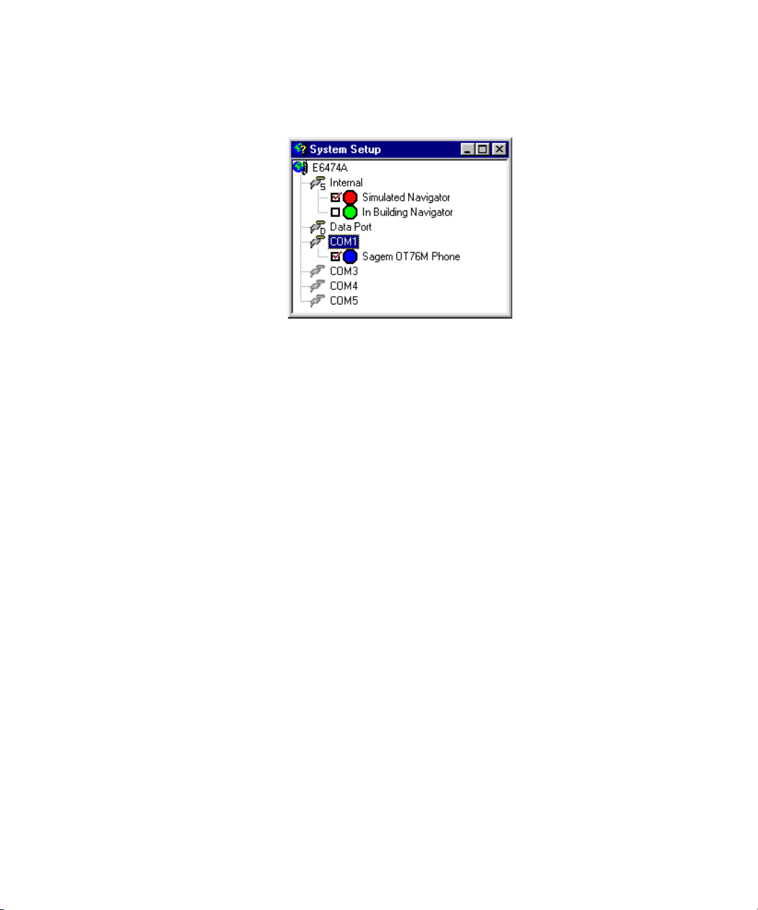
Figure 42 System Setup View with a phone identified on COM 1
Enabling the devices
Note that the check box next to each device is checked,
indicating that the device is enabled for data collection. Phones
and receivers are automatically enabled after you identify these
devices. The navigator, however is not automatically enabled.
Before you begin logging data or Live Mode, verify the following:
• Verify that each phone or receiver is enabled. Click the check
box to enable the NMEA Navigator. The navigator supplies
data to plot your position on the Route Map.
• Click the check box to enable the In-Building Navigator if you
have E6474A, option 030, indoor mapping. This allows you to
use the In-Building Route Map for manually plotting your test
route.
• Click the check box to enable the Simulated Navigator when
you need to isolate a problem, and do not require real
navigation data.
Use Your System 4
Agilent E6474A User’s Guide 83
Page 84

4 Use Your System
Configuring devices and views
Once a device has been identified by the system it needs to be
configured for measurement and data recording.
Each device has its own properties dialog box. This dialog box
allows you to set various measurement and test parameters for
that particular device.
Further test configuration can be done in the measurement
views associated with the relevant device.
To configure a device
1 Select the device.
2 Right-click on the device.
3 Select Properties from the pop-up menu. The properties
4 Step through the tabbed areas of the properties dialog box
5 Once the device properties have been configured, close the
6 Select File > Save to save your plan file.
dialog box for that device will appear.
and configure the device as required. For more information
on device properties, select F1 or click the Help button. Refer
to Figure 43 on page 85 for an example of a typical properties
dialog box.
dialog box (Select OK).
84 Agilent E6474A User’s Guide
Page 85

Use Your System 4
Figure 43 An example of a device properties dialog box
Once a device has been identified and configured, you can then
open various measurement views for displaying data and test
results.
The views available depend on the license options you have
attached to your laptop, the devices configured, and what
properties you have configured.
To configure measurement views
1 Select the View menu option.
2 Select the view you wish to display.
3 Repeat this process until you have all the information you
require.
4 Use the Window menu option to help you organize your
views.
Agilent E6474A User’s Guide 85
Page 86

4 Use Your System
Some views require further configuration once they have been
opened before they can display measurement data.
For example, the Chart View can display charts for up to four
devices. Open the view and select the properties button to start
configuring which device to chart and what data needs plotted.
Once a view has been opened, you can find out more by
selecting F1 to display the online help topic for the selected
view.
NOTE
It is recommended that you also use the Edit Label command on the
pop-up menu, to give the device a meaningful name. For Data Devices, it is
helpful if the label includes the COM port that the device is connected to.
The label will appear in the title bar of the views associated with the
device.
86 Agilent E6474A User’s Guide
Page 87

File types and locations
Use Your System 4
The Agilent E6474A system generates and uses different files.
The following list describes these files in terms of their function
and location.
File type File
extension
Plan File .spf Created when you save a project. You can
Environment File .sef Contains information about view settings in
Object Control File .ocf Contains information about each view that
Data file .sd5 Contains the recorded measurement data.
Export plan file .epf Contains the Export Wizard settings. Refer to
Description
select any location for this file.
the above plan file. This file is generated
automatically in the same location as the plan
file.
makes up the plan file you created in the
system setup view and in the E6474A
software. This file is generated automatically
in the same location as the plan file.
This file can be stored in any location. It is
recommended that the data file is saved in
the same location as the plan file.
the online help for more information on using
the Export Wizard. This file can be stored in
any location. It is recommended this file is
saved in the same location as the plan file.
NOTE
If you need to transfer a project to another laptop, it is recommended that
you copy the plan (.spf), environment (.sef), and object control files (.ocf)
at the new laptop.
Agilent E6474A User’s Guide 87
Page 88

4 Use Your System
Configuring and creating a data project
Generic data devices
Before using the Agilent E6474A software to make data
measurements, it is important that you configure the external
software and hardware. This software and hardware is used to
establish a data connection through your phone, with the phone
acting as a wireless modem. The following sections outline the
tasks you need to perform before you start the Agilent E6474A
software.
For more information, refer to:
• Phone supplier’s documentation or software
• Windows Dial Up Networking installation wizard help
• Agilent E6474A online help and tutorial
Configure the phone
Each phone is supplied with manufacturer’s documentation
that explains how to configure a phone for use as a modem
(data device). Using this documentation set up the phone’s
modem settings by navigating through the phone menu options
and entering the modem interface settings.
Add a modem connection to the computer
Instructions for adding a modem connection to the computer
and configuring it are included with the phone’s
documentation. Follow the instructions explicitly.
NOTE
88 Agilent E6474A User’s Guide
In the dialog box that prompts “Do you want Windows to detect your
modem?” be sure to check the “Don’t detect my modem; I will select it
from a list” check box option. You will also be prompted to select a COM
port on which to install the modem. For this prompt, select the COM port to
which the data device is connected.
Page 89

Use Your System 4
Configure the network and dial-up connection
Instructions for configuring the network and dial-up
Connection are included with the phone’s documentation.
Follow the instructions explicitly. There are two parts to this
procedure:
• Setting up the Internet Connection: In this part of the
procedure, you set up the dial-up connection to your service
provider. You need your service provider’s phone number.
• Advanced Connection Properties: In this part of the
procedure, you set up the Dial Up Networking (DUN)
properties, including the DNS and APN settings for your ISP.
This information is available from your service provider.
NOTE
NOTE
It is recommended that you use a logical (and meaningful) name for the
DUN connection name. You will select this as the Dial-up Name when you
configure the Data Port Properties in the E6474A software. For example,
include the phone type, service provider name, and Data Port connection
number: Sagem-MyProvider-COM3.
Testing the phone/modem configuration
The following test verifies that all phone and modem settings
are correct:
1 Using the dial-up connection you have set up, establish a
connection with the Internet.
Not all phones have integrated data and power supply connections.
Ensure the phone is fully charged before proceeding. Connect the phone to
a serial port of the computer, using the recommended connections given
to you by the phone supplier.
2 Open the browser on the computer.
3 Attempt to browse the web.
4 If this test is successful, then start the E6474A software, and
proceed to “Adding a data device" on page 90.
Agilent E6474A User’s Guide 89
Page 90

4 Use Your System
Adding a data device
Use the data port in the System Setup view to set up the device
and data properties. In the System Setup view, up to four
devices can be added to the data port. Properties for the data
device can then be configured, in a manner similar to a phone.
To add a device to the data port:
1 Right-click on the Data Port. A pop-up menu appears, as
shown in Figure 44.
Figure 44 Adding a data device
2 Choose Add Device from the pop-up menu. After you add the
data device, it is enabled, as indicated by the check mark
next to Data Device in Figure 45 on page 91.
90 Agilent E6474A User’s Guide
Page 91
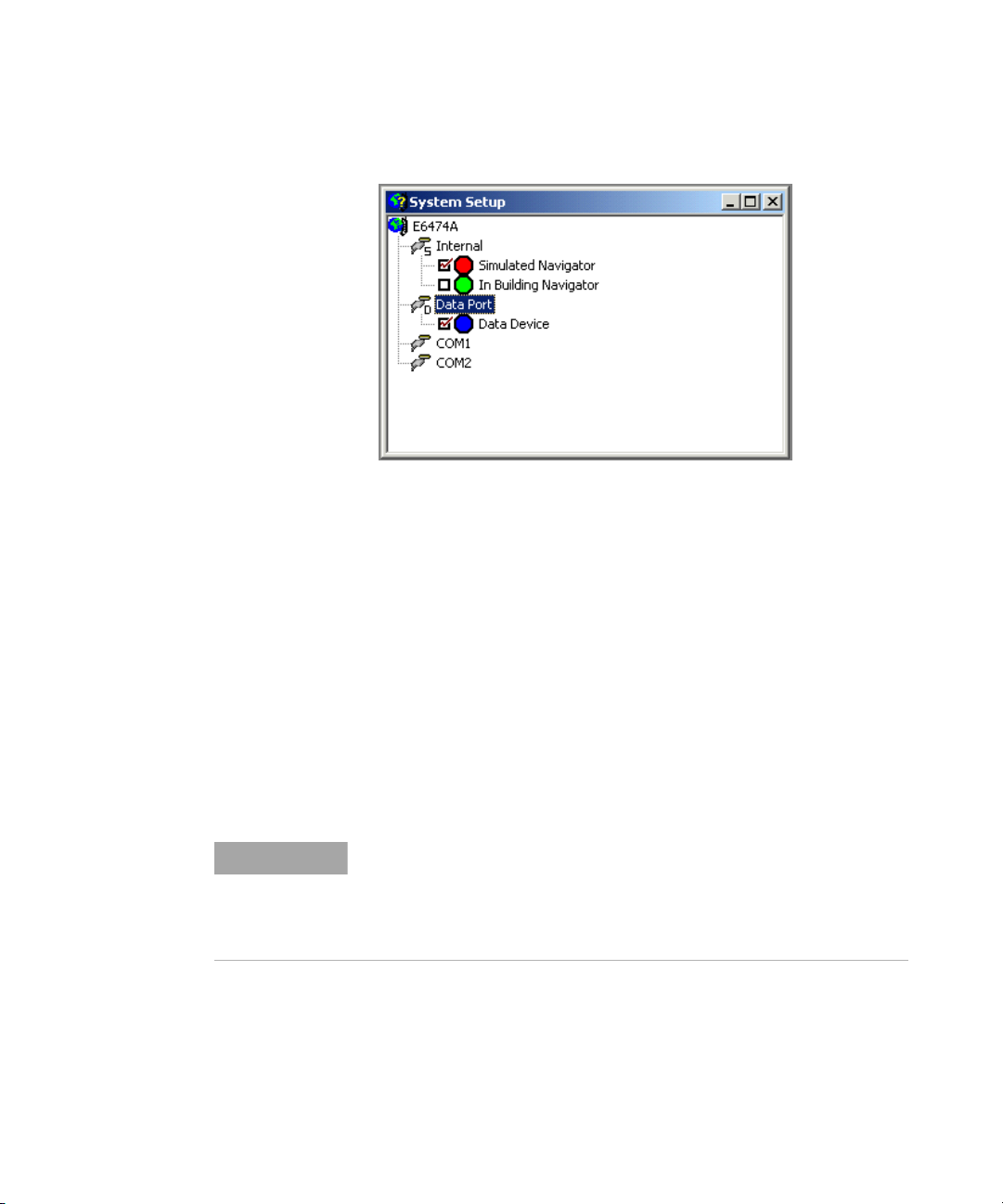
Use Your System 4
Figure 45 Data device added
Configuring data device properties
To perform throughput and timing calculations, you should use
Agilent Data Server Software. For more information on this
software and how it works, refer to the Agilent Data Server
software installation guide (E7475-90012).
Before you can perform a test with the data server, you must
configure the properties of the data device added to the data
port. The properties dialog box for the data device allows you to
configure the test conditions and parameters. See “Configuring
devices and views" on page 84 for instructions on opening this
dialog box.
NOTE
Agilent E6474A User’s Guide 91
Although the Agilent E6474A software shows the COM port in the System
Setup view that the data device is connected to, that COM port cannot be
used for configuring the device’s properties. Data Device properties can
only be configured by right-clicking on the Data Device, then choosing
Properties from the pop-up menu.
Page 92

4 Use Your System
Configuring and creating a WAMS project (Option 740)
Wireless Application Measurement Software (WAMS) is a
software application that measures user experience of wireless
data networks. It can be used in a drive test environment, as
well as in a stationary environment. The following are some of
the key features in WAMS:
• Shell application that allows easy creation, scheduling, and
running of tests.
• Allows simultaneous measuring of multiple wireless
networks.
• Allows integration of GPS for accurate time and location
stamps.
• Easily exports measured data to an Excel like CSV files.
• Integrates with QoS DMS and Report engine, which allows
near real time performance monitoring of multiple probes.
• Allows easy creation and integration of custom made and
third party tests.
To start the WAMS interface
1 Open the E6474A application.
2 Select Tools > WAMS Sequencer.
The WAMS sequencer view opens with a default sequence tree.
To configure a WAMS sequence
A WAMS sequence is made up from test nodes and tests
designed to measure typical user experience of wireless data
networks.
Full details on configuration and the tests are provided in the
Wireless Application Measurement Software (WAMS) User’s
Guide (E6474-90058).
An online version (PDF format) can be found in the Help >
Library.
92 Agilent E6474A User’s Guide
Page 93

Agilent E6474A
User’s Guide
5
Get results fast
What you’ll find in this chapter
To d o th is See this
WARNING
Learn to use the
software
Get information about
taking measurements
Drivers should not operate the Agilent E6474A system while the
vehicle is in motion.
“Using Quick Basics — the Online Tutorial" on
page 94
“Online Help" on page 96
Agilent Technologies
93
Page 94

5 Get results fast
Using Quick Basics — the Online Tutorial
As part of the product, the Agilent E6474A includes Quick
Basics, an online tutorial. The opening screen is shown in
Figure 46. It is recommended that you complete Quick Basics
before you use the Agilent E6474A system.
Figure 46 The E6474A Quick Basics tutorial
Quick Basics provides an overview of the capabilities of the
Agilent E6474A. It also demonstrates the most common tasks
you’ll perform, and then guides you through those tasks in a
simulation of the program.
94 Agilent E6474A User’s Guide
Page 95

To run the tutorial
Do this See this
Get results fast 5
After the Tutorial
When you have finished running the tutorial, you can continue
learning about the system by reviewing these and other online
help topics:
•What’s New to familiarize yourself with changes from the
•Getting started for basic information on using the software
•How do I… for valuable how-to information on using the
• And, of course, the online help provides details about every
1 Click Start > Programs > Agilent
Wireless Solutions > E6474A >
Reference > Tutorial.
2 Read the Welcome page and then
click Topic Menu.
3 To see an overview of the Agilent
E6474A, click Quick Tour.
4 When you have completed Quick
Basics, or want to exit, close the
browser windows.
latest release
and getting help
software
aspect of the software, as well
The tutorial opens in your browser
window.
The Topic menu lists the Key Features
and Quick Tour, as well as the
available procedures.
View the Quick Tour and then choose
the procedures that interest you or
view them in order to get a good
introduction to the software.
The Quick Basics is closed. Run it
again any time for a brush up.
Agilent E6474A User’s Guide 95
Page 96

5 Get results fast
Online Help
The software includes context-sensitive, HTML-based online
help. In the help, you’ll find all the information you need to
make measurements with the Agilent E6474A software,
including procedures, measurement parameters, and tips. The
help opens in a browser window, separate from the E6474A
application window.
Accessing Online Help
1 Press the F1 key or click the Help button, when shown, to
display the help topic with detailed information about the
options, check boxes, and text boxes.
2 For help on configuring a view, open the view, then press F1.
96 Agilent E6474A User’s Guide
Page 97

Get results fast 5
Figure 47 shows the Contents tab on the left, and a typical help
topic on the right.
Figure 47 A typical online help browser display
The online help can also be accessed in the following ways:
• Click Start > Programs > Agilent Wireless Solutions >
E6474A > Help > E6474A Help.
• With the E6474A software running, click Help > Help Topics
to open the Help menu and a list of items that are new for the
current software release.
Agilent E6474A User’s Guide 97
Page 98
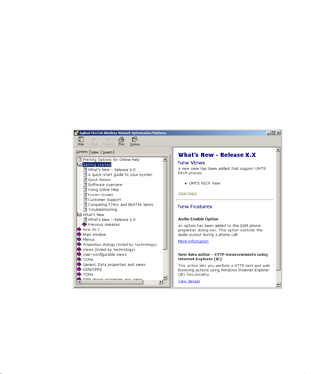
5 Get results fast
Using Online Help
Following are some tips for using the software’s online help
system.
Getting familiar with new features
When you display the online help from the Help menu, a list of
new software features automatically appears in your browser as
shown in Figure 48.
Figure 48 The What’s New topic
This topic lists and briefly describes each new feature for the
current release of the software. You can display detailed
info rm ation for any new feature by clicking the View topic link.
98 Agilent E6474A User’s Guide
Page 99

Get results fast 5
Using the contents tab
The Contents tab lists all the topics in the online help.
1 Click the Contents tab to look at the topics by category.
2 Click a plus (+) sign or double-click a book icon to view its
contents. It may include more Book icons or topics.
3 Click a topic to open that topic in the Help window.
Using the index tab
The Index tab lets you search through an alphabetical list of
topics to find those relating to the text you type in the text field.
1 Click the Index tab to look at the list of index entries.
2 Type your subject in the Type Keywords box.
Or, scroll through the list in the list of entries, and
double-click the term to list topics.
3 If more than one topic is available for the keywords you
selected, a Topics found box appears from which you can
select the topic of interest.
4 Double-click a topic to view it in the Help window.
Using the search tab
The Find tab lets you search the online help to find topics that
include the words or phrases you type in the text box.
1 Click the Search tab to search for words or phrases used in
the help topics.
2 Type the word or Phrase you are looking for in the text box.
3 Click the List Topics button to display topics that contain the
word or phase you enter in the bottom list box.
4 Double-click a topic to open the help window for that topic.
Getting Information about Views
To learn about the views available for a device, follow these
steps:
1 Start the online help.
2 Click the Contents tab.
Agilent E6474A User’s Guide 99
Page 100

5 Get results fast
3 Open the book for the phone or receiver.
4 Open the View Menu topic.
5 Click the links for the views listed.
100 Agilent E6474A User’s Guide
 Loading...