

Page 1

Agilent E6474A
Wireless Network
Optimization Platform
User’s Guide
Agilent Technologies
Page 2

Notices
CAUTION
WARNING
© Agilent Technologies, Inc. 2009
No part of this manual may be reproduced in
any form or by any means (including electronic storage and retrieval or translation
into a foreign language) without prior agreement and written consent from Agilent
Technologies, Inc. as governed by United
States and international copyright laws.
Manual Part Number
E6474-90090
Edition
16 July 2009
Agilent E6474A, Release 14.0 or later
Printed in Malaysia
Agilent Technologies
South Queensferry
EH30 9TG, Scotland, UK
Acknowledgements
MapInfo ® is a registered trademark of
MapInfo Corporation.
Pentium ® is a registered trademark of Intel
Corporation.
Adobe ® is a trademark of Adobe Systems
Incorporated.
Windows XP is U.S. registered trademarks
of Microsoft Corporation.
iDEN ® is a registered trademark of
Motorola, Inc.
WiMAX” is a trademark of the WiMAX
Forum. “WiMAX Forum” is a registered
trademark of the WiMAX Forum.
All other trademarks are the property of
their respective holders.
Warranty
The material contained in this
document is provided “as is,” and is
subject to being changed, without
notice, in future editions. Further, to
the maximum extent permitted by
applicable law, Agilent disclaims all
warranties, either express or implied,
with regard to this manual and any
information contained herein,
including but not limited to the
implied warranties of merchantability
and fitness for a particular purpose.
Agilent shall not be liable for errors or
for incidental or consequential
damages in connection with the
furnishing, use, or performance of this
document or of any information
contained herein. Should Agilent and
the user have a separate written
agreement with warranty terms
covering the material in this
document that conflict with these
terms, the warranty terms in the
separate agreement shall control.
Tec hn ol og y L i ce ns es
The hardware and/or software described in
this document are furnished under a license
and may be used or copied only in
accordance with the terms of such license.
Restricted Rights Legend
If software is for use in the performance of a
U.S. Government prime contract or subcontract, Software is delivered and licensed as
“Commercial computer software” as
defined in DFAR 252.227-7014 (June 1995),
or as a “commercial item” as defined in FAR
2.101(a) or as “Restricted computer software” as defined in FAR 52.227-19 (June
1987) or any equivalent agency regulation or
contract clause. Use, duplication or disclosure of Software is subject to Agilent Technologies’ standard commercial license
terms, and non-DOD Departments and
Agencies of the U.S. Government will
receive no greater than Restricted Rights as
defined in FAR 52.227-19(c)(1-2) (June
1987). U.S. Government users will receive
no greater than Limited Rights as defined in
FAR 52.227-14 (June 1987) or DFAR
252.227-7015 (b)(2) (November 1995), as
applicable in any technical data.
Safety Notices
A CAUTION notice denotes a
hazard. It calls attention to an
operating procedure, practice, or
the like that, if not correctly
performed or adhered to, could
result in damage to the product
or loss of important data. Do not
proceed beyond a CAUTION
notice until the indicated
conditions are fully understood
and met.
A WARNING notice denotes a
hazard. It calls attention to an
operating procedure, practice,
or the like that, if not correctly
performed or adhered to, could
result in personal injury or
death. Do not proceed beyond a
WARNING notice until the
indicated conditions are fully
understood and met.
2 Agilent E6474A User’s Guide
Page 3

Welcome to Agilent E6474A Wireless Network Optimization Platform
Thank you for choosing Agilent Technologies. In this User’s
Guide, you will find the instructions you need to set up the
hardware and begin using the software to take
measurements.
About this guide
This guide contains installation and operating instructions
for the Agilent E6474A Wireless Network Optimization
Platform software.
See this chapter For this information
1 Get Ready A list of tasks to perform before you get started.
2 Install the Software Instructions for installing the E6474A software.
3 Set Up Your System Setup instructions and cable connections for each
component of your systems.
4 Use Your System • Powering up systems.
• Starting and using the software.
5 Get Results Fast • Using the online training demonstrations.
• Accessing and using online help.
6 Getting Assistance, If
You N e ed I t
• Getting telephone support.
• Frequently asked questions.
• Returning systems for service.
• Solving problems.
• Contacting customer support.
• Updating E645xC receiver firmware.
Additional information
This guide is designed to provide you with a smooth,
successful installation and setup. In addition to this guide,
the online help provides information on the user interface,
views, system panels and configuration, as well as in- depth
information about how to use the E6474A software. The
software also contains over two hours of video training
material that helps you get the most from the application.
Agilent E6474A User’s Guide 3
Page 4

4 Agilent E6474A User’s Guide
Page 5

Contents
About this guide 3
1 Get Ready 11
Unpacking your boxes 11
Before installing the software 12
2 Installing the Software 13
What is on the CD 14
Install the E6474A software 15
Install Analysis Reporter software 17
Verifying your software installation 19
Support & Software Update Service (SUS) Registration
Procedure 20
Registration process 21
Add an additional contact person 24
3 Set Up Your System 27
Phones 28
Overview 28
Phone connection using a USB port 28
Phone connection using direct serial (RS-232) port 28
Agilent Digital Receivers 29
Overview 29
Connecting a single W1314A receiver 30
Connecting multiple W1314A receivers 30
Agilent E6474A User’s Guide 5
Page 6

Power Distribution Module (PDM) for the W1314A
Receivers 32
Using a Combiner antenna connection (Agilent W1314A) 33
Connecting a single E645xC receiver 34
Connecting multiple E645xC receivers 35
Pulse trigger E645xC receivers 37
GPS 39
Overview 39
Agilent digital receiver internal GPS 39
Agilent digital receiver external GPS 39
Indoor positioning 43
Batteries 44
Checking the remaining charge 44
Charging the battery 45
Safe handling and disposal 45
Indoor Setup 47
Overview 47
Setting up the timing module 47
How to switch batteries during calibration 51
Cable connections for indoor hardware 51
Cable routing through the shoulder straps 54
How to reset the 1PP2S output on the timing module 56
License Manager 58
Introduction 58
For more information 59
4 Use Your System 61
Tur n i n g t he po w er on 62
Battery charging 62
Starting the software 63
6 Agilent E6474A User’s Guide
Page 7

To start the software 63
Using the software 64
Overview 64
Introduction - Starting the application 65
Creating a new project 65
Creating a new file 67
To u r o f t he Us e r I n te rf a c e 69
Adding Hardware 71
Tour of Data Items 79
The Sequencer 81
Views 84
Mapping 89
How to add and configure an indoor map 98
Collecting Data 101
Events 104
Sharing Projects and Data 111
5 Get Results Fast 119
Using the Online Training 120
To open a training topic 120
Online Help 121
Accessing Online Help 121
To s ea r ch t he h e lp 121
Documentation Library 122
6 Getting Assistance, If You Need It 123
Troubleshooting your E6474A system 124
Device communication problems 124
Setting an iDEN phone’s baud rate 125
Agilent E6474A User’s Guide 7
Page 8

Toshiba phone power-up issues 125
Online Frequently Asked Questions 127
Updating Receiver Firmware 128
Replacement firmware security key 130
Contacting Customer Support 131
Technical telephone assistance 131
Numbers to call 131
Returning the System for Service 132
Warranty repair 132
Preparing the system for shipping 133
A Safety and Regulatory Information 135
Warning and caution notices 135
General safety considerations 135
Installation, Use, and Storage 136
Signal and input power 137
Symbols 137
Declaration of Conformity - Agilent E64xx RF Receivers 139
Declaration of Conformity - Agilent W1314A Receivers 140
B Connection Panels and LED Indicators 141
Agilent W1314A Receivers 142
E645xC Receiver 143
Trimble Placer GPS 455DR 144
Fei-Zypher Timing Module 145
8 Agilent E6474A User’s Guide
Page 9

C Specifications 147
Computer Hardware and Software Requirements 148
Battery Specifications (W1314A-070) 149
Charger specifications 150
Battery disposal 150
Power cable 150
Receiver Specifications 151
W1314A receiver specifications 152
E6450C CDMA PCS 1.9 GHz receiver specifications 154
E6451C GSM900 receiver specifications 156
E6452C CDMA/TDMA cellular band receiver
specifications 158
E6457C Japan CDMA cellular band receiver
specifications 160
E6453C GSM1800 and Korean CDMA band receiver
specifications 162
E6454C 1.9 GHz CDMA/GSM1900 receiver specifications 164
E6455C 2.1 GHz W-CDMA/UMTS/cdma2000 receiver
specifications 166
E6456C 1.9 GHz W-CDMA/UMTS/cdma2000 receiver
specifications 168
E6458C GSM 850 receiver specifications 170
E6458C-100 GSM/UMTS 850 and PCS 1900 receiver
specifications 172
E7456C iDEN/CDMA RF receiver specifications 174
W1314A Antenna Specifications 176
Phone Support 177
Options and Part Numbers 178
W1314A replacement parts list 178
Antenna kit part numbers 178
Agilent E645xC receivers 179
Agilent E6474A User’s Guide 9
Page 10

Hardware included with E6474A software licenses 180
D Permanent In-Vehicle Hardware Installation 181
In-Vehicle Installation Guidelines 181
Recommended Tools 183
Installation Overview 183
Installing the Mounting Plate 184
Attaching the Receiver to the Mounting Plate 185
Installing the PDM in the Vehicle 186
Mounting the E645x receiver 189
Antenna Installation 190
Installation guidelines 190
1 Index 191
10 Agilent E6474A User’s Guide
Page 11
Agilent E6474A
NOTE
User’s Guide
1
Get Ready
Unpacking your boxes
The Agilent E6474A system is a modular system so your
delivery may arrive as a collection of boxes. Carefully
unpack each box and locate the following items:
• License key(s).
• Installation CD.
• License documents.
• Order details (order number, packing list).
Do not connect any hardware at this stage.
Agilent Technologies
11
Page 12

1 Get Ready
Before installing the software
Once you have identified your delivered items and before
connecting any hardware or installing any software, check
you have these items:
• A PC that meets the minimum requirements (refer to
“Computer Hardware and Software Requirements" on
page 148).
• Agilent E6474A installation CD.
• A valid license key
• Fully charged phone batteries (Refer to “Phones" on
page 28).
If you are unclear about any items you have received, please
contact us as soon as possible. Refer to Phone support
“Contacting Customer Support" on page 131.
1
.
1 If you have purchased the software licensing option, then you must have access
to your companies software license server (IP address). Refer to “License
Manager" on page 58.
12 Agilent E6474A User’s Guide
Page 13

Agilent E6474A
NOTE
User’s Guide
2
Installing the Software
What you’ll find in this chapter
To d o t hi s See this
Find out what’s on the CD. “What is on the CD" on page 14.
Install the E6474A system software. “Install the E6474A software" on
page 15.
Install Analysis Reporter “Install Analysis Reporter
software" on page 17
Verify your installation. “Verifying your software
installation" on page 19.
Support & Software Update Service
(SUS) Registration Procedure
Do not connect any hardware at this stage.
Refer to “Set Up Your System" on page 27 for more information on
hardware configuration.
“Support & Software Update Service
(SUS) Registration Procedure" on
page 20.
Agilent Technologies
13
Page 14

2 Installing the Software
NOTE
What is on the CD
The Agilent E6474A software CD includes:
• Release Notes
• The E6474A application software
• The Agilent E6474A Analysis Reporter software
• Default project files and views
After installation of the main Agilent E6474A software the
following items are added to your PC:
• The E6474A application software
• Folders containing hardware drivers
• Default projects and views
• All documentation, including help and training files
It is recommended that you read the Release Notes before you install the
software.
The Release Notes include information that may not appear in this guide.
It also lists all the new features and enhancements made since the last
released version.
14 Agilent E6474A User’s Guide
Page 15

Install the E6474A software
NOTE
CAUTION
CAUTION
Version 11.0 onwards of the Agilent E6474A software requires Software
and Support Update Service (SUS) Licenses. Data logging can not be
performed without a valid SUS license.
For reliable operation of the Agilent E6474A application it is
recommended that you defragment your hard-drive before installation.
The Agilent E6474A application can integrate with many external
devices which provide large amounts of data, therefore efficient disk
access is important for optimal performance.
Vista OS - It is recommended that you switch off the User Account
Control option to enable all the features of the E6474A application.
Installing the Software 2
Agilent E6474A User’s Guide 15
Follow these steps.
Do This Notes
1Insert the Agilent E6474A CD. This CD contains the required
software device drivers.
2 Your system may have autostart or go to
the Start button, click Run and type D:\
setup (where D is your CD drive).
3 Follow the installation instructions.
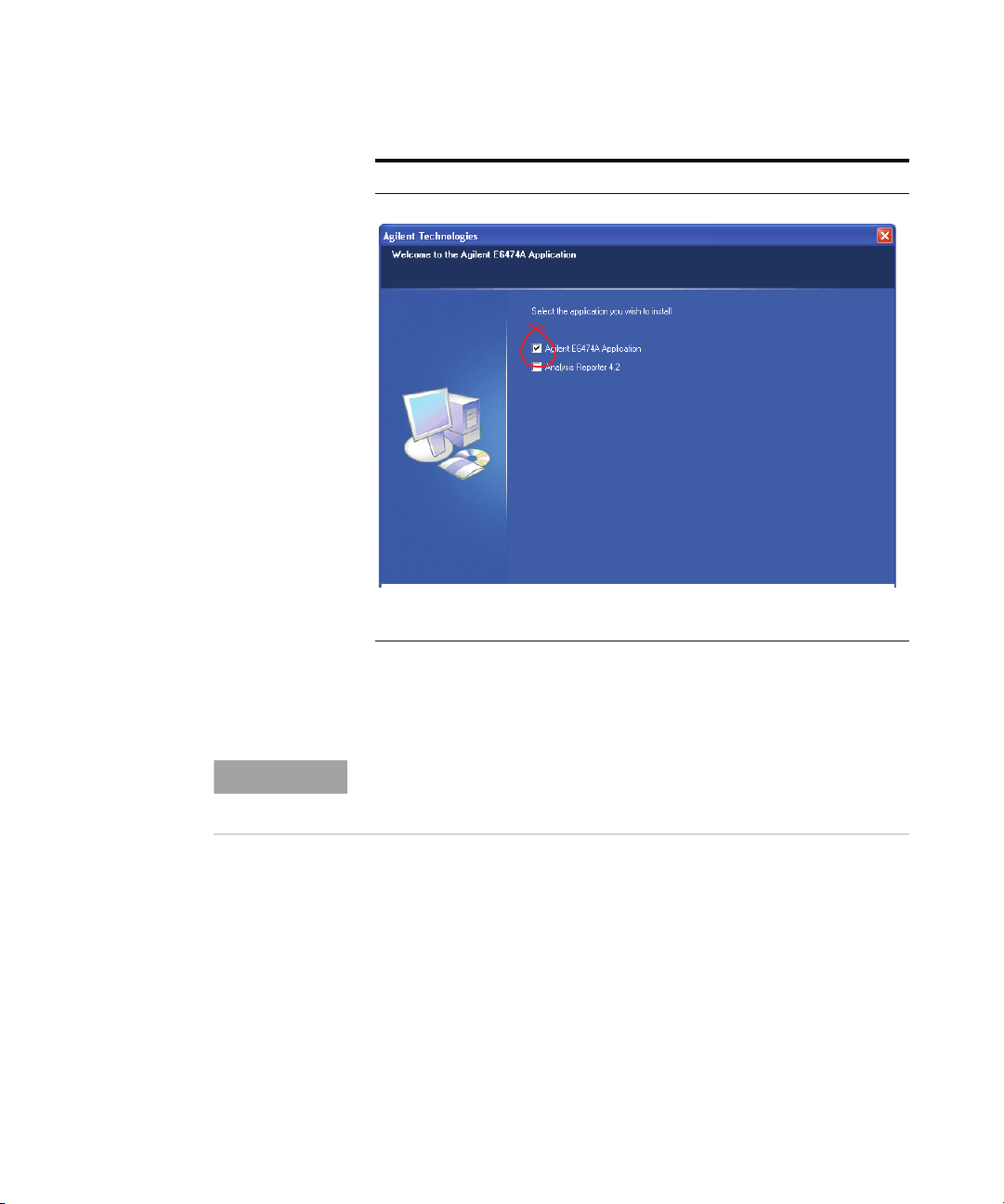
4 Select the Agilent E6474A-X installation
option.
The installation dialog box
appears. Refer to Figure 1.
Page 16
2 Installing the Software
NOTE
Do This Notes
16 Agilent E6474A User’s Guide
Figure 1 Select Agilent E6474A-X Application to install this
application
At the end of the installation process you have the option to
review the release notes.
The Release Notes include information that may not appear in this guide.
It also lists all the new features and enhancements made since the last
released version.
Page 17

Install Analysis Reporter software
The Analysis Reporter (Agilent E6474A-758) option is a
simple to use post- processing report tool. You must have
purchased the E6474A- 758 option to run this software.
Follow these steps.
Do This Notes
1Insert the Agilent E6474A CD. This CD contains the required
Installing the Software 2
software device drivers.
2 Your system may have autostart or go to
the Start button, click Run and type D:\
setup (where D is your CD drive).
3 Follow the installation instructions If you have a previous version
4 Select the Analysis Reporter installation
option
The installation dialog box
appears.
installed on your PC your will be
prompted to over-write it with
the newer version.
See below, Figure 2 on page 18.
Agilent E6474A User’s Guide 17
Page 18

2 Installing the Software
Do This Notes
Figure 2 Select Analysis Reporter to install this application
18 Agilent E6474A User’s Guide
Page 19
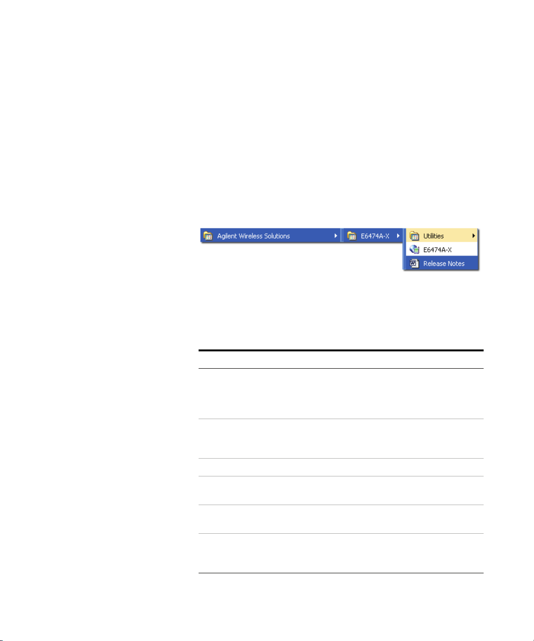
Verifying your software installation
Once you have installed the E6474A software you can verify
the installation using the following method.
An option will appear in your program listing.
Select Start > All Programs > Agilent Wireless Solutions
> E6474A- X and you should see a new program group and
items added to your program listing. Refer to Figure 3.
Figure 3 Menu item options after installation
Start the software and check your license options
Installing the Software 2
Do the following.
Do this Notes
1 Attach your USB license dongle to
your PC or obtain a valid license
from your license server, if
applicable.
2 Select Start > All Programs >
Agilent Wireless Solutions >
E6474A-X > E6474A-X.
3 Select Help > About E6474A-X The About E6474A dialog box appears.
4 Confirm you have the version of
software you ordered.
5 Select the License Info button The License Information dialog box
6 Confirm the license descriptions
match your ordered license
options.
This also applies to parallel license
dongles. Your PC should automatically
detect the USB license dongle. Refer to
“License Manager" on page 58.
The E6474A software starts. Refer to
“License Manager" on page 58.
appears.
If no license descriptions appear in this
dialog box, check that you have properly
connected a valid license dongle.
Agilent E6474A User’s Guide 19
Page 20

2 Installing the Software
Support & Software Update Service (SUS) Registration Procedure
This section outlines the procedure for registering your SUS
agreement. If you have any questions about this process,
please contact the support team at:
wsp_support@agilent.com
What is in your SUS order
Your SUS order should include the following items and
information:
• The SUS order option, refer to the list below:
One year standard SUS 060
One year corporate SUS (for greater than 50 systems) 061
One year Tech Tool SUS 062
3 Years Drive Test SUS -Support and Software Update Service 063
3 Year Corporate SUS (for greater than 50 systems) 064
3 Years Drive Test Tech Tool SUS - Support & Software Update Service 065
5 Years Drive Test SUS - Support & Software Update Service 066
5 Years Drive Test Corporate SUS - Support & Software Update Service 067
5 Years Drive Test Tech Tool SUS - Support & Software Update Service 068
• The order includes a dongle with a valid SUS Basic or
SUS Tech Tool license (6 months, 1 year, 3 years or
5years).
• An entitlement certificate (This may not have been issued
if the SUS license was provided as a demo or trial license
prior to September 2007). The certificate provides
instructions and how to register.
20 Agilent E6474A User’s Guide
Page 21
Registration process
The following procedure outlines the procedure for
registering your SUS license. The benefits and features of
registration are provided at the end of this section (refer to
“Benefits of SUS registration" on page 24).
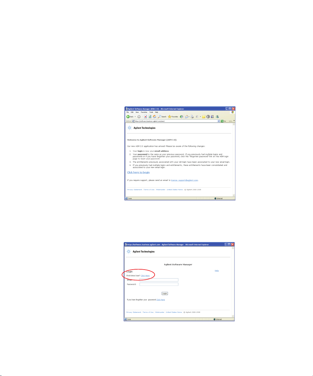
1 Go to http://www.agilent.com/comms/softwaremanager
(refer to Figure 4)
Installing the Software 2
Figure 4 Initial start-up screen
2 Select the “Click here to begin” link.
3 Select the “First time user? Click here” link. This takes
you to the first stage of the registration process (refer to
Figure 5).
Figure 5 Login - first time user
Agilent E6474A User’s Guide 21
Page 22
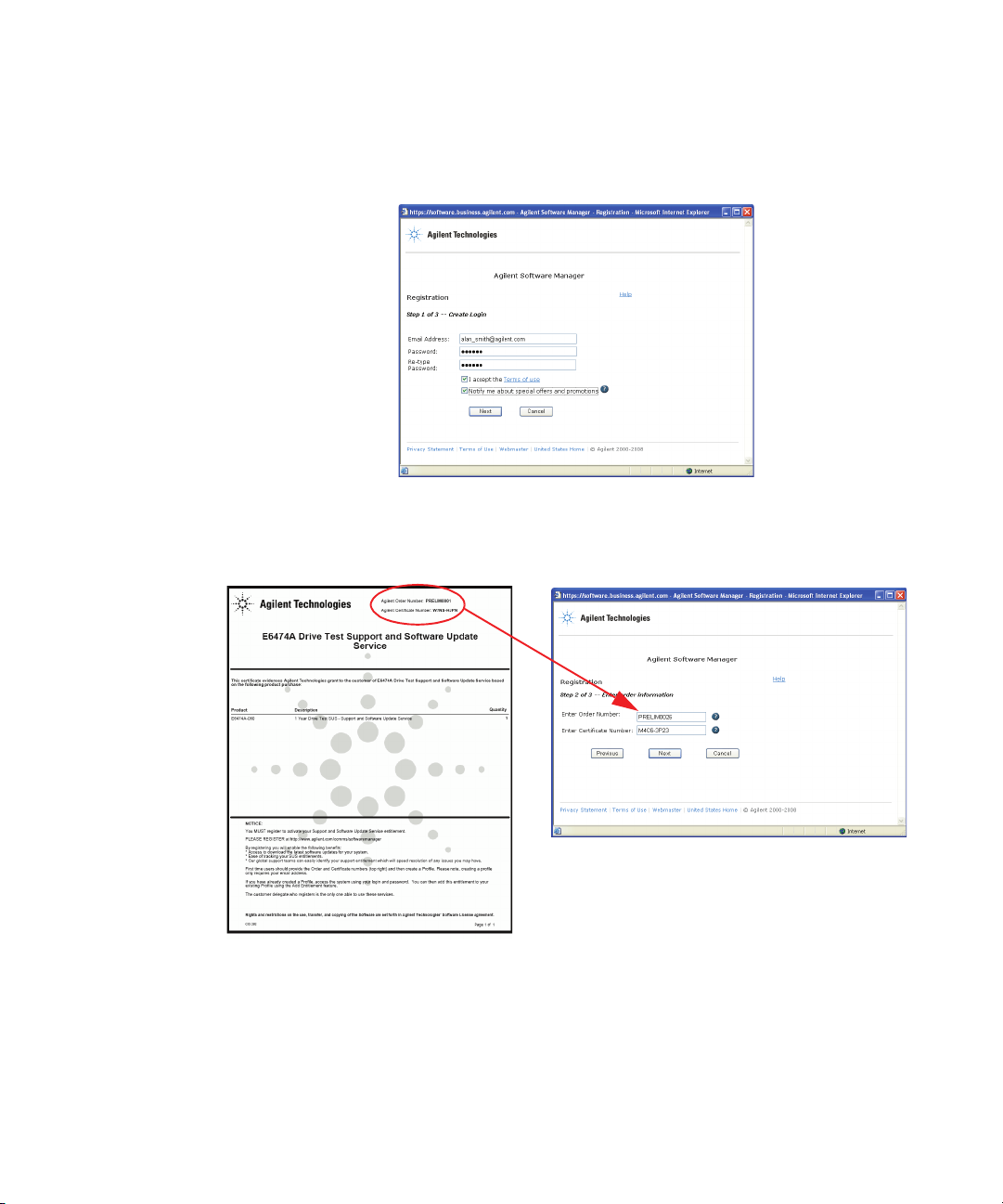
2 Installing the Software
4 Enter a valid e- mail address and password (refer to
Figure 6) and select next.
Figure 6 Registration part 1 of 3
5 Enter your order number and certificate number. These
numbers can be found at the top of the SUS license
document (refer to Figure 7) and select next.
Figure 7 Registration part 2 of 3
22 Agilent E6474A User’s Guide
Page 23
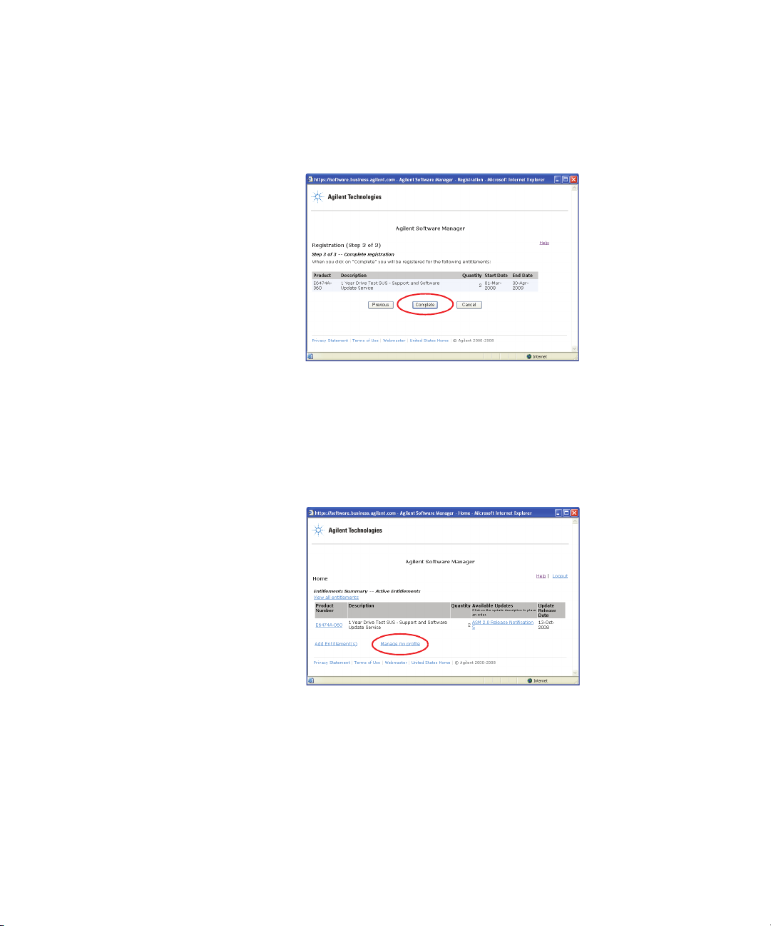
Installing the Software 2
6 You are shown the details of your SUS license agreement.
Check the details are correct and then select “Complete”
to finish the registration process (refer to Figure 8).
Figure 8 Registration part 3 of 3
To ensure you get the best support from Agilent it is
important that we have accurate and up to date contact
details for your company. Once you have registered you are
taken to the Agilent Software Manager home page. Follow
this procedure to complete your contact details:
1 Select the “Manage my profile” link (refer to Figure 9).
Figure 9 Manage my profile link
2 Enter your contact details. Please complete as much of
the form as possible so that we can ensure we get in
Agilent E6474A User’s Guide 23
Page 24
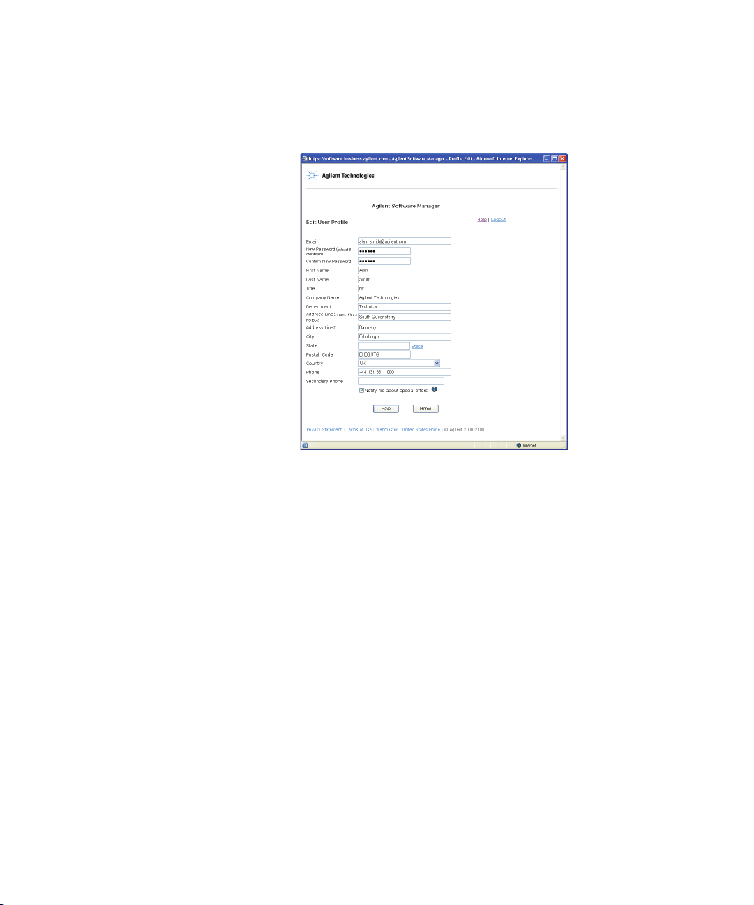
2 Installing the Software
touch with the right person in your company (refer to
Figure 10).
Figure 10 Edit your user profile form
3 Select “Save” when you have completed the form.
Add an additional contact person
To ensure you get the best support from Agilent it is
important that we have a secondary contact person in your
company. Having another person to contact means that you
will not missing any important updates or information if the
primary contact is not available.
To add a secondary contact in your company to the same
license agreement, follow the procedure used for first- time
registration, using the same agreement number and order
number but this time enter the second contact person’s
details
Benefits of SUS registration
Registration is important so you can get the most from their
SUS license. The registration process entitles you to:
24 Agilent E6474A User’s Guide
Page 25

Installing the Software 2
• You can change your contact profile, including password
changes.
• You have access to the latest software downloads and
updates.
• Tracking of SUS licences and orders.
• Quicker and easier access to the support team which
leads to quicker resolution of any outstanding issues or
questions you may have.
Agilent E6474A User’s Guide 25
Page 26

2 Installing the Software
26 Agilent E6474A User’s Guide
Page 27

Agilent E6474A
NOTE
User’s Guide
3
Set Up Your System
What you’ll find in this chapter
To d o t hi s See this
How to connect phones “Phones" on page 28
How to connect receivers “Agilent Digital Receivers" on
page 29
Information about batteries “Batteries" on page 44
How to set up and configure an
indoor system
How to use the License Manager
software
Do not connect hardware until you have installed the Agilent E6474A
software. Refer to “Install the E6474A software" on page 15.
“Indoor Setup" on page 47
“License Manager" on page 58
Agilent Technologies
27
Page 28

3 Set Up Your System
NOTE
Phones
Overview
Phone connection using a USB port
The Agilent E6474A system supports a wide range of phones
and data communication devices. A list of the currently
supported phones can be found in the documentation
library. To access this list open the E6474A software and
select Help > Library.
Phones can be connected to your system using the following
methods:
Phone battery charging and audio monitoring are not supported with direct
connect phones.
Most phones can be connected to your system using USB
interface cables.
The USB drivers used by these phones may require custom
installation processes. Follow the phone manufacturer’s
instructions for configuring USB phone connections. It is
recommended that you read the phone manufacturer’s
instruction before you connect any devices to your laptop.
Phone connection using direct serial (RS-232) port
Depending on the type of phone you wish to connect to your
laptop, it may be possible to connect the phone directly to
your laptop serial (RS- 232) port.
Refer to the phone manufacturer’s instructions before
connecting a phone.
28 Agilent E6474A User’s Guide
Page 29

Agilent Digital Receivers
NOTE
Overview
Set Up Your System 3
Agilent manufactures a range of digital RF receivers that
cover most technologies. All receivers are supplied with an
internal GPS systems. For technical details of the available
receivers, refer to “Receiver Specifications" on page 151.
Receivers can be connected and configured using the
following methods:
Receiver configuration
Connecting a single W1314A receiver page 30
Connecting multiple W1314A receivers page 30
Using the power distribution module (PDM) (W1314A) page 32
Using the Diplexer antenna connector (W1314A) page 33
Connecting a single E645xC receiver page 34
Connecting multiple E645xC receivers page 35
Pulse trigger the E645xC receivers page 37
For details on how to upgrade the Agilent receiver firmware, refer to
“Updating Receiver Firmware" on page 128.
Refer to
Agilent E6474A User’s Guide 29
Page 30
3 Set Up Your System
RF IN
W1314A-120
Quad Band Receiver
9-34VDC
18W TYP
48W MAX
GPS
ANT.
GPS
1PPS
TEMP
STAT
450-496, 921-962 MHz
1800-1885, 2100-2180 MHz
+10 dBm (10 mW) MAX
20 VDC MAX
!
GPS
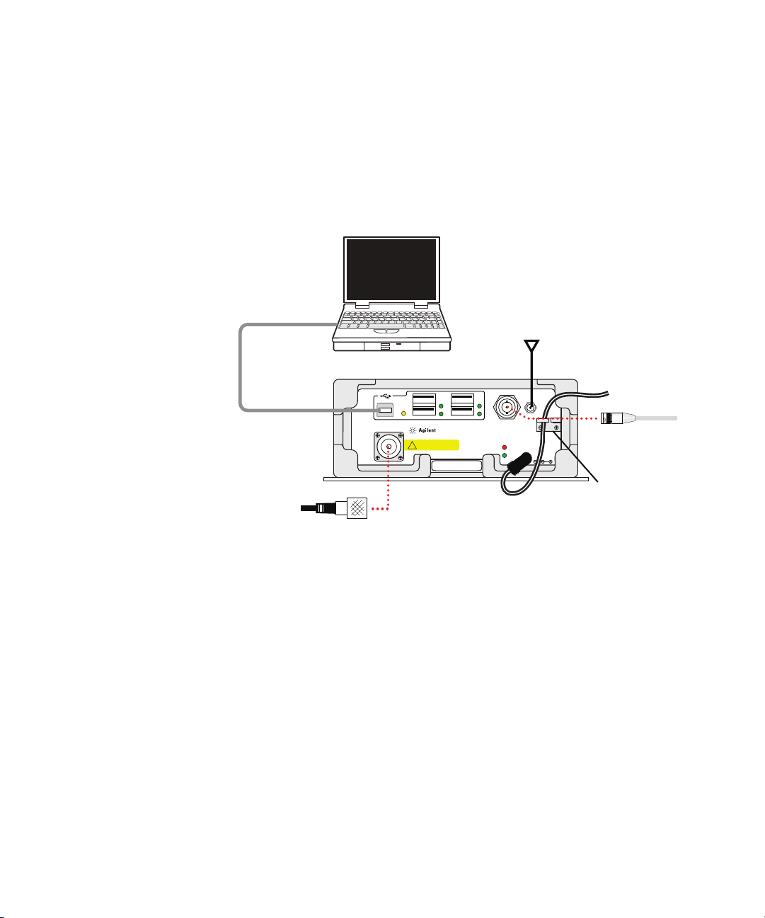
antenna
Master USB
to computer
BNC connector
for 1 pulse per
second (optional)
Power
cable
Cable
retainer
Type-N to TNC
adapter for RF
antenna connection
Laptop
Receiver
Connecting a single W1314A receiver
A standard configuration for a single receiver includes the
following cables and connections. Refer to Figure 11.
30 Agilent E6474A User’s Guide
Figure 11 Cabling a single receiver
Connecting multiple W1314A receivers
A standard configuration for daisy chained receivers
includes the following cables. Refer to Figure 12 on page 31.
Page 31

RF IN
W1314A-120
Quad Band Receiver
9-34VDC
18W TYP
48W MAX
GPS
ANT.
GPS
1PPS
TEMP
STAT
450-496, 921-962 MHz
1800-1885, 2100-2180 MHz
+10 dBm (10 mW) MAX
20 VDC MAX
!
RF IN
W1314A-120
Quad Band Receiver
9-34VDC
18W TYP
48W MAX
GPS
ANT.
GPS
1PPS
TEMP
STAT
450-496, 921-962 MHz
1800-1885, 2100-2180 MHz
+10 dBm (10 mW) MAX
20 VDC MAX
!
RF IN
W1314A-120
Quad Band Receiver
9-34VDC
18W TYP
48W MAX
GPS
ANT.
GPS
1PPS
TEMP
STAT
450-496, 921-962 MHz
1800-1885, 2100-2180 MHz
+10 dBm (10 mW) MAX
20 VDC MAX
!
RF IN
W1314A-120
Quad Band Receiver
9-34VDC
18W TYP
48W MAX
GPS
ANT.
GPS
1PPS
TEMP
STAT
450-496, 921-962 MHz
1800-1885, 2100-2180 MHz
+10 dBm (10 mW) MAX
20 VDC MAX
!
+-
BATTERY
GPS Antenna
Master USB to computer
USB to next receiver
in daisy chain
BNC connector
for 1 pps
BNC connector
for 1 pps
Power
Cable
Laptop
1 pulse per second
1 pulse per second
1 pulse per second
PDM
Type-N to TNC
adapter for RF
Antenna
connection
BNC-T
BNC-T
Set Up Your System 3
Figure 12 Cabling multiple receivers
Agilent E6474A User’s Guide 31
Page 32

3 Set Up Your System
CAUTION
5 amp fuses
PDM on/off
switch
Ignition
sense switch
On LED
Low Voltage
LED
Power Distribution Module (PDM) for the W1314A Receivers
The PDM provides power from the vehicle's battery to a
single or multiple receivers. Alternatively, you can power
receivers from the IEC power outlets (cigarette lighter). On
the rear of the PDM is the power cable that attaches to the
battery and connections for up to four receivers. On the
front of the PDM (see Figure 13 on page 32) you'll find the
following:
• On/off switch
• The ignition sense switch, if enabled will sound a warning
when the ignition switch is turned off. The sound warning
will repeat every minute and, after approximately 20
minutes, the power will be stopped to the attached
receivers. This gives you time to close the drive- test
software and power off equipment. If ignition sense is in
the off position, the PDM will operate independently of
the vehicle ignition.
If the PDM is on and the vehicle ignition is off, the battery will drain in
as little as one hour.
• One fuse per receiver to protect receiver power output.
These can be replaced using an automotive blade- type
5amp fuse.
Figure 13 The rear view of the PDM plate
32 Agilent E6474A User’s Guide
Page 33

Set Up Your System 3
NOTE
Refer to “Installing the PDM in the Vehicle" on page 186 for
more information about PDM in- vehicle installation.
Using a Combiner antenna connection (Agilent W1314A)
Use a combiner to obtain signals from two different
antennas.
For some options of receivers, a single antenna cannot
provide coverage for all available bands. These receivers are
supplied with two antennas and a combiner. In situations
where multiple bands need to be scanned, you will need to
use the combiner to provide adequate RF signal strength.
The combiner and cables add insertion loss, slightly reducing the
sensitivity of the receiver.
Connect the receiver to the combiner unit using the SMA
(M) to N-Type (M) cable. Then connect the two antennas to
the combiner unit using the SMA (M) to N- Type (F)
connector adapters. Refer to Figure 14 on page 34.
Agilent E6474A User’s Guide 33
Page 34

3 Set Up Your System
RF IN
W1314A-120
Quad Band Receiver
9-34VDC
18W TYP
48W MAX
GPS
ANT.
GPS
1PPS
TEMP
STAT
450-496, 921-962 MHz
1800-1885, 2100-2180 MHz
+10 dBm (10 mW) MAX
20 VDC MAX
!
W1314A Receiver
W1314-80027 Cable (SMA Male to N-Type, 2ft/0.7m)
W1314-80025 Combiner
2-way 350 MHz to 600 MHz
W1314-80026 Connector Adapter
SMA Male to N-Type Female
W1314-80026 Connector Adapter
SMA Male to N-Type Female
W1314-80024 Antenna
(Magnetic Mount)
2.3 GHz to 6 GHz
W1314-80023 Antenna
(Magnetic Mount)
700 MHz to 2700 MHz
RF In Port
Figure 14 Detailed connection information
Connecting a single E645xC receiver
The Agilent digital receiver can be connected directly to the
serial port of your laptop. The direct serial port connection
provides RF measurement information and GPS coordinate
results.
34 Agilent E6474A User’s Guide
Page 35

Set Up Your System 3
Serial port
RF Antenna
If your PC does not have an RS-232 serial port you can use
a serial to USB convertor. Agilent recommends the Agilent
E5805A (USB/4- port RS- 232 Interface Module). When using
other USB interface models, ensure that they support HS
serial communication.
Refer to Figure 15 on page 35 for typical serial port
connection (this diagram does not include a GPS antenna).
Figure 15 Serial port connection for Agilent digital receiver
Connecting multiple E645xC receivers
When you configure multiple receivers, only one receiver
(the master receiver) is physically connected to the
computer and is able to supply input from the GPS. You
attach an external GPS system (unless it has internal GPS)
to the master receiver only. The other receiver(s) receive
their GPS signal from the master receiver. If other receivers
contain internal GPS systems, their GPS is ignored.
If your PC does not have an RS-232 serial port you can use
a serial to USB convertor. Agilent recommends the Agilent
E5805A (USB/4- port RS- 232 Interface Module). When using
other USB interface models, ensure that they support HS
serial communication.
Agilent E6474A User’s Guide 35
Page 36

3 Set Up Your System
To connect multiple E645xC receivers:
1 Attach one end of a short cable to the RX LOOP IN
connector on the master receiver. Attach the other end of
the short cable to the RX LOOP OUT of the second
receiver.
2 Continue to attach receivers (up to a total of four
receivers) as in step 1.
3 When all receivers are connected with short cables,
connect one end of a long cable to the RX LOOP OUT
connector on the master receiver to the RX LOOP IN on
the last receiver in the series.
4 Connect the serial port of your laptop to the RS- 232 port
of the master receiver with an RS- 232 null modem cable.
5 Connect the RF antenna to the RF input of each of the
receivers.
6 Connect the GPS antenna to the SMA GPS Connector of
the master receiver.
36 Agilent E6474A User’s Guide
Refer to Figure 16 on page 37.
Page 37

Set Up Your System 3
Figure 16 Connecting more than one receiver to your laptop
Pulse trigger E645xC receivers
The E645xC receivers accommodate a pulse trigger device.
The triggering device requirements are:
• Cable with BNC male connector (the Agilent pulse trigger
cable input is female BNC)
• Falling- edge trigger
• TTL threshold
• 15 volt maximum pulse level
• 100 nanosecond minimum pulse width of period
• 300 microsecond minimum pulse
Agilent E6474A User’s Guide 37
Page 38

3 Set Up Your System
Follow the manufacturer’s instructions for installing the
pulse trigger device. Connections to the receiver are shown
in Figure 17.
• If you have two receivers, connect the pulse trigger cable
(E7450- 60015) to the R
X LOOP IN and RX LOOP OUT ports
as shown in Figure 17.
• Or, if you have one receiver, connect the pulse trigger
cable to the R
X LOOP IN and RX LOOP OUT ports of the
same receiver.
• Connect the cable from the pulse trigger device to the
BNC connector of the pulse trigger cable. For software
configuration and calibration instructions, refer to the
online help. Search for “wheel pulse unit setup” to locate
the information.
Figure 17 Connecting the pulse trigger cable
38 Agilent E6474A User’s Guide
Page 39

GPS
Set Up Your System 3
Overview
To provide accurate measurement analysis and signal
synchronization, the Agilent E6474A system provides
comprehensive methods of support for Global Positioning
Systems (GPS).
The Agilent E6474A system obtains its GPS signal from a
variety of sources. GPS systems can be connected and
configured using the following methods:
GPS configuration
Agilent digital receiver internal GPS page 39
Agilent digital receiver external GPS page 39
Indoor positioning page 43
Agilent digital receiver internal GPS
All Agilent digital receivers are supplied with an internal
GPS system. When an Agilent digital receiver is connected to
your system, this GPS device is automatically detected. GPS
signals are passed to your system through the serial or USB
connection.
Agilent digital receiver external GPS
The following examples show a complete system with various
external GPS systems attached through an Agilent E645xC
digital receiver. These examples show the external GPS and
receiver connected to a PC.
Refer to
Agilent E6474A User’s Guide 39
Page 40

3 Set Up Your System
Example 1 - Using the internal GPS with a differential GPS antenna.
Figure 18 Internal GPS with optional differential GPS
Example 2 - Using Placer GPS 455
In this example the external GPS unit is connected using an
adapter box. The adapter box is connected to the GPS
RS- 232 port on the receiver.
Refer to Figure 19 on page 41.
The adapter box is connected to the MDT/RTCM and Digital
IO ports.
40 Agilent E6474A User’s Guide
Page 41

Figure 19 External GPS - Placer 455
Set Up Your System 3
Example 3 - Placer 455 with differential GPS
Refer to Figure 20 on page 42.
1 Connect the RTCM port of the Trimble- supplied
communications cable to the differential GPS receiver,
using the RS- 232 null modem cable included with the
system. Connect the remaining port of the
Trimble- supplied communications cable to the MDT/RTCM
port of the Trimble Placer GPS 455 unit.
2 Connect the digital port of the adapter box to the Digital
IO port of the Trimble Placer GPS 455 unit, using the
RS- 232 cable.
3 Connect the MDT/RTCM port of the adapter box to the
MDT port of the Trimble- supplied communications “T”
cable, connected to the Differential, using the RS- 232
cable.
Agilent E6474A User’s Guide 41
Page 42

3 Set Up Your System
4 Connect the GPS antenna to the GPS ANT port of the
Trimble Placer GPS 455 unit. Agilent Technologies
recommends that a “bulkhead mount” GPS antenna be
used whenever possible for improved performance.
Figure 20 Placer 455 GPS with differential GPS
42 Agilent E6474A User’s Guide
Page 43

Indoor positioning
The Agilent E6474A system supports indoor measurements.
Mapping and recording data for indoor environments
requires the following items:
• Detailed floor and building plan (BMP or JPG format).
• Pen tablet laptop (preferred).
• 1 PP2S signal for receiver measurement synchronization.
For full details on how to perform indoor measurements and
configure the indoor positioning and tracking, refer to
“Indoor Setup" on page 47 and the online help.
Set Up Your System 3
Agilent E6474A User’s Guide 43
Page 44

3 Set Up Your System
PUSH
100
75
50
25
Li-ION
Battery
test
button
LEDs
NOTE
Batteries
Checking the remaining charge
Press the test button shown in Figure 21 to check the
remaining charge capacity.
LEDs Lit Capacity Remaining
4 76% to 100%
3 55 to 75%
2 26% to 50%
1 10% to 25%
1 Blinking Less than 10%
Figure 21 Battery test button
When using the booster module attached to the battery,
battery status can be seen from the LEDs on the top of the
booster module.
When there is no battery status indication from the LEDs then the battery
discharge may be critical. You should charge the battery as soon as
possible. Refer to the documentation provided with the battery and battery
charger units.
44 Agilent E6474A User’s Guide
Page 45

Charging the battery
NOTE
The battery can be charged within the carry bag or in a
standalone docking station. Disconnect the charger from the
battery before checking the charge. The battery is fully
charged when all four LEDs are lit.
1 Connect the battery charger cable to the battery.
2 Plug the battery charger’s AC power cord into a 100- 240V
AC 50-60Hz power source.
3 Allow approximately five hours to fully charge the battery.
The battery is defined as a consumable part and is only covered by a 90
day warranty.
Safe handling and disposal
For the safe use of lithium- ion batteries, always follow the
instructions provided below. Improper handling of
lithium-ion batteries may result in injury or damage from
electrolyte leakage, heating, ignition, or explosion. Batteries
must be recycled or disposed of properly.
Set Up Your System 3
Agilent E6474A User’s Guide 45
Page 46

3 Set Up Your System
WARNING
Always use the battery charger provided with the battery.
Never heat or incinerate the battery.
Never impact, pierce, or crush the battery.
Never disassemble or modify the battery. The battery contains a
circuit designed to enhance safety. Damaging this circuit may cause
overheating, fire or bursting.
Never charge a battery under high temperature conditions, such as
near a fire or in the direct sunlight. If the ambient temperature is too
high, the protection circuit may be actuated, preventing further
charging, or damage.
Never short-circuit the battery by connecting the positive and
negative terminals with a metal material.
Do not store or carry the battery where it could come into contact
with metal objects such as a key chain or necklace.
Never allow the battery to get wet or be immersed in water.
Do not place the battery in a microwave oven or high-pressure
container.
46 Agilent E6474A User’s Guide
Stop charging if the battery is not charged after the prescribed
charge time.
If leakage of the electrolyte occurs, or if there is an offensive odor,
keep the battery away from any source of fire or spark.
If you become aware of any abnormal phenomena, such as odor,
discoloration, or deformation, during use, while charging, or when
storing the battery, remove the battery from the device or charger
and stop using.
In the event the electrolyte comes into contact with the eyes, flush
thoroughly with clean water, without rubbing. Consult with a
physician immediately.
Page 47

Indoor Setup
Set Up Your System 3
Overview
This section contains instructions for setting up a portable
or indoor system using the W1314A receiver. Always charge
all batteries before beginning a survey.
The indoor hardware includes:
• A standard backpack
• Two batteries (one battery is fitted with a power booster
module)
• One Agilent W1314A receiver
• One timing module (1PP2S output)
• Cables and connections
The timing module provides a 1PP2S signal for the receiver
measurements.
Setting up the timing module
Before the timing module can be used, the 1PP2S output
needs to be calibrated against GPS timing signals. This can
take between 4 and 8 hours depending on GPS signal
strength.
Follow this procedure to calibrate your timing module:
1 Install the GPSMon
PC. Refer to the manufacturer’s installation instructions.
2 Connect the timing module to your laptop using the
RS232 port. Refer to Figure 22 on page 48.
1 The GPSMon software and documentation can be found in the following
directory and folder:
C:\Program Files\Agilent Technologies\E6474A-X\Drivers\GPSMon
Double click on GPSMon.msi to start the installation process.
Agilent E6474A User’s Guide 47
1
software on any compatible laptop or
Page 48

3 Set Up Your System
GPSMon software
Timing Module
Fully charge battery
GPS antenna
At least four satellites
(optional mains AC)
ANT
1 PPS
RS-232
10 MHz
Li-ION
100
75
50
25
PUSH
Figure 22 Timing calibration connections
3 Connect the GPS antenna to the timing module (ANT
SMB).
4 Connect a fully charge battery, with the booster module
fitted, to the timing module. A fully charge battery lasts
approximately 16 hours.
5 Start the GPSMon software. Refer to Figure 23 on
page 49.
48 Agilent E6474A User’s Guide
Page 49

Set Up Your System 3
Number of satellites obtained
Timing module status
Timing module lock status
Figure 23 GPSMon software interface at start of timing process
6 (optional) Connect an AC power supply to the timing
module. This has the advantage of charging the battery
while still providing power during the timing calibration
process.
1
7 Position the GPS antenna where is can easily obtain at
least four strong GPS signals over the whole training
process. This is known as the warm- up period.
8 Ensure the antenna, and any other equipment, is
adequately protected from adverse weather conditions.
9 When the calibration process is completed the timing
module will indicate a locked status. Refer to Figure 24
on page 50.
1 The battery is charged at the same time as the timing module is being trained.
However the re-charge time for the battery is increased when connected to the
timing module.
Agilent E6474A User’s Guide 49
Page 50

3 Set Up Your System
At least four satellites
Timing module status
CAUTION
Figure 24 GPSMon software interface at the end of the timing process
Do not remove power from the timing module during calibration and
while configuring your hardware. Doing so will lose GPS satellite lock
and the calibration process will have to be re-started.
If the battery attached to the timing module does need replaced during
calibration, follow the procedure; “How to switch batteries during
calibration" on page 51.
The amount of time that you can use the trained timing
module depends on how long you had the timing module
locked onto a valid signal.
For example, if you have trained the timing module for four
hours then the recommended period of use for collecting
valid indoor data would also be four hours. Similarly if the
module is trained for 8 hours then you can collect data for 8
50 Agilent E6474A User’s Guide
hours.
Page 51

How to switch batteries during calibration
NOTE
If, during calibration, you need to change the battery supply
for the timing module, follow this procedure:
1 Connect the AC adaptor power supply to the booster
cable charging port.
2 Ensure the AC power is on.
3 Carefully remove the battery from the cable.
4 Replace the battery with a fully charge unit.
5 Remove the AC adaptor power supply.
Cable connections for indoor hardware
Once the timing module has been calibrated, you can
connect the hardware for indoor measurement. Refer to
“How to add and configure an indoor map" on page 98 for
more information on configuring the E6474A software.
Refer to Figure 25 on page 52 for cable connection
information. This diagram does not show the backpack and
battery pouches.
Set Up Your System 3
Do not disconnect power to the timing module after the calibration period.
This may cause the lose of the timing synchronization 1PP2S signal.
Agilent E6474A User’s Guide 51
Page 52

3 Set Up Your System
PUSH
100
755025
Li-ION
To RF Antenna
USB connection
to laptop
1PP2S connection
Timing Module
Battery with
Battery
W1314A Receiver
booster module
GPS
GPS
ANT.
1PPS
+10 dBm (10 mW) MAX
u
20 VDC MAX
W1314A-120
Quad Band Receiver
RF IN
450-496, 921-962 MHz
1800-1885, 2100-2180 MHz
755025
Li-ION
100
9-34VDC
TEMP
18W TYP
STAT
48W MAX
PUSH
ANT
Figure 25 Indoor hardware cable connections
1 PPS
CONTROL
10 MHz
Ensure that all cables and holding straps for the equipment
are securely locked into position before you start your
indoor testing.
Where possible, use the USB ports built into the receiver,
when connecting phones or other test devices.
Refer Figure 26 on page 53 for a recommended layout for
the hardware inside the backpack.
52 Agilent E6474A User’s Guide
Page 53

RF Antenna
USB connection
to your laptop
Battery for
W1314A Receiver
Timing
Battery for
Timing Module
1PP2S connection
Agilent W1314A
Receiver
Backpack
Module
Set Up Your System 3
Figure 26 Backpack hardware layout
Agilent E6474A User’s Guide 53
Page 54

3 Set Up Your System
Cable routing through the shoulder straps
Refer to Figure 27 for a cable routing example.
1 Route the USB cable (E6473- 60005) through either
shoulder strap.
2 If the phones are be attached to the shoulder straps,
route the phone interface cables through either shoulder
strap.
Figure 27 Routing cables through the shoulder straps
54 Agilent E6474A User’s Guide
Page 55

Set Up Your System 3
Adjusting the backpack harness
1 Loosen all straps and place the pack on your back as
shown in Figure 28.
Figure 28 Tightening the shoulder straps on the backpack
2 Fasten the waist belt and tighten it so that it rests on
your hips. The waist belt should always remain on your
hips, even after the harness is adjusted.
3 Tighten up the shoulder straps until the pack feels
comfortable. The weight of the pack should be carried on
your hips for maximum comfort. The shoulder straps help
stabilize the pack on your body.
4 Connect the chest strap. You can change the vertical
position so that the strap fits comfortably across your
chest. The sternum strap reduces shoulder fatigue and
increases mobility by pulling the shoulder straps inward.
Agilent E6474A User’s Guide 55
Page 56

3 Set Up Your System
How to reset the 1PP2S output on the timing module
The timing module is factory configured to provide a 1PP2S
timing pulse. If, however, the timing pulse has been changed
to 1PPS
timing module output.
This procedure requires the GPSMon software to
communicate with the timing module. Refer to the timing
module manufacturer’s instruction for installing and
configuring the GPSMon software.
1 Connect the timing module to your laptop
2 Provide power to the timing module using a battery or AC
3 From the GPSMon software, select Setup > Ref Pulse
1
, then use the following procedure to change the
mains
Control. Refer to Figure 29
Figure 29 Open the Ref Pulse dialog box
4 In the Ref Pulse Control dialog box, select 1PP2S option.
Refer to Figure 30 on page 57
1 This may occur when a factory reset command is sent to the module.
56 Agilent E6474A User’s Guide
Page 57

Set Up Your System 3
Set 1PP2S option
Figure 30 Setting the 1PP2S option
5 Select OK
The timing should now be set to 1PP2S.
Agilent E6474A User’s Guide 57
Page 58

3 Set Up Your System
NOTE
License Manager
Introduction
Agilent E6474A software requires Software and Support Update Service
(SUS) licenses. Without a valid SUS license you will not be able to collect
quires
measurement data, design views or add and edit events, although you will
be able to playback recorded data.
Software options can be enabled using one of two methods:
• Software license keys (also called “Dongles”) that are
attached to either the USB or parallel port on your
computer. The software license key included with the
E6474A software contains the licenses for the software
options you have purchased.
• Keyless software licenses from a software license server
(E6474A- 081). Software licensing provides the ability to
maintain a pool of measurement licenses on a server and
then distribute those licenses to client drive- test PCs
using a check- out process. Typically only one server
application is required per customer.
License Manager software is automatically installed when
you install the E6474A software. This software allows you to:
• Transfer licenses between keys included (for example,
between the DB25 parallel key and USB key)
• Add software options to your license key
• Transfer licenses between keys
• Check- out software license from a network- based server
• Transfer licensed product options between license keys
• View online help on the use of License Manager features
58 Agilent E6474A User’s Guide
Page 59

For more information
For complete instructions on using the License Manager,
please refer to the Welcome topic in the License Manager
software’s online help.
1 To start the License Manager, select Programs > Agilent
Wireless Solutions > E6474A- X > Utilities > License
Manager.
2 Click Help > Help topics to open the online help topics.
Set Up Your System 3
Agilent E6474A User’s Guide 59
Page 60

3 Set Up Your System
60 Agilent E6474A User’s Guide
Page 61

Agilent E6474A
User’s Guide
4
Use Your System
What you’ll find in this chapter
To d o t hi s See this
Tur n i ng t h e p o w er o n “Turning the power on" on page 62
Starting the software “Starting the software" on page 63
Using the software “Using the software" on page 64
This chapter tells you how to start configuring and using
your system.
Agilent Technologies
61
Page 62

4 Use Your System
CAUTION
Turning the power on
Battery charging
Before switching on any system component, ensure that the supply
voltages are in the specified ranges. Refer to “Computer Hardware and
Software Requirements" on page 148.
• For a portable system, verify that the batteries (indoor
system configuration), phone, and computer batteries are
fully charged before beginning data collection. Refer to
“Batteries" on page 44 for more information.
• For an in- vehicle system, verify that the phone and car
batteries are fully charged before beginning data
collection.
62 Agilent E6474A User’s Guide
Page 63

Starting the software
To start the software
Use Your System 4
Detailed information about the software is available from the
online help. It is assumed that the software has already been
installed. If not, refer to “Install the E6474A software" on
page 15 for installation instructions.
1 To start the software, click Start > All Programs >
Agilent Wireless Solutions > E6474A- X > E6474A-X.
Refer to Figure 31.
Figure 31 Starting E6474A software
2 When the software starts, a copyright screen is briefly
displayed. This is followed by the welcome screen (Refer
to Figure 31 on page 63).
Confirm your license options
Once the software has started, check your license options.
To check your license options.
1 With the application open, select Help > About E6474A...
2 Select the License Info... button.
A dialog box appears listing the detected license options. If
you do not see any license options in this dialog box, check
that you have a valid license key properly attached to your
system.
Agilent E6474A User’s Guide 63
Page 64

4 Use Your System
Using the software
Overview
The E6474A application gives you a choice how to manage
your data files. The two modes are project mode (default)
and file mode. Once you have chosen you mode of operation,
the user interface and procedures for configuring the system
are the same.
Project Mode Overview
In Project Mode (default mode) drives are grouped together
as collections of data files under a common named hardware
configuration. When you click on a project you can see a list
of all the related drives collected with it. Refer to the online
help for more information about this mode.
File Mode Overview
64 Agilent E6474A User’s Guide
In File Mode however, each drive is treated as a discrete file,
which can be named at collection time and transferred
between PC's using the normal Windows Explorer. Refer to
the online help for more information about this mode.
Page 65

Introduction - Starting the application
Select this button to view an
animated demonstration of the
application
Choose a project type and select
this button to open and view a
typical example project
Select this button to start
the application
When you first open the E6474A, the following screen
appears (Figure 32).
Use Your System 4
Agilent E6474A User’s Guide 65
Figure 32 Welcome screen
Creating a new project
Before you add hardware and configure your test
environment, you can open the application in project mode
and create a project. A project contains all your
configuration information and drive test results. A project is
created using the project manager.
Once you have selected the project manager the project
mode is automatically enabled.
Page 66

4 Use Your System
Select Project Manager
Select New Project
Enter a project name
How to create a new project:
1 Select File > Project Manager (Figure 33). Shortcut key -
F5.
Figure 33 Project manager
2 In the project manager window select the New Project
icon (Figure 34).
Figure 34 New project icon
3 (Optional) Select a template project. A template project
contains pre- defined views and layout.
4 Enter a name for your project (Figure 35).
Figure 35 Project name
66 Agilent E6474A User’s Guide
Page 67

Use Your System 4
Default User Interface
5 Select OK. The project will be added to your project
manager list and will become active. At the same time the
user interface will open with the default layout
(Figure 36) or with the layout defined in the template, if
selected. Close the Project Manager to access the active
project.
Agilent E6474A User’s Guide 67
Figure 36 Default user interface (project mode)
For more information on the project manager and how to
use it, refer to the online help.
Creating a new file
Before you add hardware and configure your test
environment, you can open the application in file mode. A
file contains all your configuration information and drive
test results in a single file.
Once you have selected the file mode the mode is shown in
the title bar of the application.
Page 68

4 Use Your System
Select New
Default User Interface
How to create a new file:
1 Select File > New (Figure 37).
Figure 37 File mode
2 The user interface will open with the default layout
(Figure 38).
68 Agilent E6474A User’s Guide
Figure 38 Default user interface (file mode)
For more information on file mode and how to use it, refer
to the online help.
Page 69

Tour of the User Interface
Main menus
Control icons
Online help
Device and view
property panel
Test sequencer status and log views
Data items and
Hardware panel
Main workspace
sequencer panels
Once you have created a project, the default user interface is
opened. Almost every part of the user interface can be
moved and changed to suit your needs. Figure 39 shows the
typical parts of the user interface.
Use Your System 4
Agilent E6474A User’s Guide 69
Figure 39 Default user interface
Description of user interface
Here is more information about the areas listed in Figure 39
on page 69.
Main menus The main menus give you access to the most
common tasks you may need to perform. They also let you
start other tools such as the export wizard and the cellsite
importer.
Page 70

4 Use Your System
NOTE
Control icons The control icons provide quick access to
common tasks associated with controlling drive data
collection and view creation.
Online help The online help panel provides access to
detailed descriptions of all parts of the application and how
you can get the most from it.
Main workspace The workspace area is where all your views
are displayed. It is possible to have multiple workspaces
(tabbed).
Select F11 to dock (minimize) all the system panels. This maximizes the
workspace area and provides you with more space for view and
measurement display.
Device and view property panel This system panel lists all the
properties of the active view or device. This panel lets you,
for example, set up voice call properties, data sequencer,
chart colors, measurement limits and more.
Sequencer status and log views These two system views
report the status of any test sequence. The sequencer status
view displays the progress of the test sequence while the
sequencer log view displays the test results as they are
reported by the system.
Data item and sequencer panels The data items system panel
displays all the measurements that are available for display
on any view you wish to configure. Data items are dragged
and dropped onto views. The sequencer panel displays
user- configured test sequences.
Hardware panel The hardware panel is the area where you
add and configure hardware that is to be used with your
drive test.
70 Agilent E6474A User’s Guide
Page 71

NOTE
Hardware does NOT need to be connected to your system for it to be
Right-click here
added to the hardware list. This lets you configure a project without the
need for you to have all the hardware.
Adding Hardware
Hardware can be added to a project even if the device is not
available or not connected to your laptop. This is useful if
you have a limited number of test devices or you need to
configure projects remotely from your test area.
Adding hardware (Manually - no devices connected to your laptop)
Follow this procedure:
1 In the hardware panel, right- click on hardware.
Use Your System 4
(Figure 40)
Agilent E6474A User’s Guide 71
Figure 40 Hardware panel
Page 72

4 Use Your System
Select Add Device
Select device
2 Select Add Device from the pop-up menu. (Figure 41)
Figure 41 Add device option
3 Expand the list of available devices and select the device
you want to add to your project (Figure 42).
Figure 42 Expanded list of devices
4 The device is added to your hardware list and is shown
as not connected. The data items, available from the
72 Agilent E6474A User’s Guide
Page 73

Use Your System 4
Device added to
Data items added
hardware panel
device, are shown in (Figure 43) the data items system
panel.
Figure 43 Hardware and data item lists
Adding hardware (Automatically - with devices connected to your laptop)
The device add wizard is used to add hardware
automatically to your laptop. This wizard steps you through
the connection process. Then at the end of the process,
devices are detected and connected.
Agilent E6474A User’s Guide 73
Page 74

4 Use Your System
Right-click here
Select Device Wizard
Follow this procedure:
1 In the hardware panel, right- click on hardware.
(Figure 44)
Figure 44 Hardware panel
2 Select Device Wizard... from the pop- up menu.
(Figure 45)
Figure 45 Device add wizard option
74 Agilent E6474A User’s Guide
Page 75

Use Your System 4
3 When Add Device Wizard is opened, step through the
wizard until all your devices are detected. (Figure 46)
Figure 46 Device add wizard dialogs
4 Once the application has scanned and detected your
devices they are added to the hardware list and the
device is shown as connected. Also data items, available
from the device, are shown below in the data items
system panel. (Figure 47 on page 76).
Agilent E6474A User’s Guide 75
Page 76

4 Use Your System
Device added to hardware
Data items added
panel and shown as connected
76 Agilent E6474A User’s Guide
Figure 47 Connected device and data items list
Adding receiver measurements
Unlike a typical phone device, the Agilent digital receiver is
capable of providing different sets of measurements. To
access these measurement sets you need to add a receiver
measurement after you have added the receiver hardware.
Page 77

Use Your System 4
Select Add Measurement
To add a receiver measurement after you have added a
receiver to the hardware list, follow this procedure:
1 Right- click on the receiver hardware.
2 Select Add Measurement. (Figure 48)
Figure 48 Add a receiver measurement
Agilent E6474A User’s Guide 77
Page 78

4 Use Your System
Select a measurement
3 Choose the measurement you wish to add to the receiver.
(Figure 49)
Figure 49 Select a measurement to add
78 Agilent E6474A User’s Guide
4 Select the added measurement to configure the
measurement properties. (Figure 50) Properties that need
Page 79

Use Your System 4
Properties of the measurement
Added measurement
NOTE
configured are pre- selector bands, channels to be used
and measurement types to be made.
Agilent E6474A User’s Guide 79
Figure 50 Properties of added measurement
As each measurement is added to the receiver in the
hardware list, the data items are updated with new items
that can be used on views. A receiver does not need to be
connected to your system for measurements to be added.
Tour of Data Items
Once hardware has been added to your project (manually or
automatically), data items are added to the data items
system panel. Data items are used to build views.
All data items and measurements are shown. However, only licensed
measurements will display measurement data in your views.
Page 80

4 Use Your System
Expand the data items list to
see the available measurements
Drag and drop data items onto views
Figure 51 shows an example of the data items list.
Figure 51 List of data items in the data items system panel
Data items can be dragged and dropped onto views. Refer to
“Views" on page 84 for more information on views and view
configuration.
Multiple data items can be selected and dragged onto views.
(Figure 52)
80 Agilent E6474A User’s Guide
Figure 52 Drag and drop data items
Page 81

The Sequencer
Select a device to add
Use Your System 4
In the E6474A application all tests are configured and
controlled using the ‘tree- like’ sequencer system panel. The
tests available provide a comprehensive range of test
scenarios from a simple voice call test to full data network
testing including internet connection, FTP, SMS and video
testing (dependant on you having valid licenses for these
tests).
To create a test sequence
Follow this procedure:
1 Once you have added hardware, right- click on the service
model in the sequencer system panel.
2 Select New > Device > YourDeviceName. (Figure 53)
Figure 53 Add a device
Agilent E6474A User’s Guide 81
Page 82

4 Use Your System
Select a test to add
3 Right- click on the device and select New > Test > [Select
the test you wish to add]. (Figure 54)
Figure 54 Add a test
Repeat step 3 to build up your test sequence.
Repeat step 2 to add more tests for other devices.
Tests can be cut, copied, deleted or moved in the sequencer
tree.
82 Agilent E6474A User’s Guide
Page 83

Use Your System 4
Sequencer test
Properties of the test
Once you have created your test sequence you can configure
individual tests using the properties panel (Figure 55) on
the right side of the user interface. Select each test to
display the properties for that test.
Figure 55 Sequencer and properties
Agilent E6474A User’s Guide 83
Page 84

4 Use Your System
Two d ev ic es
Parallel test sequences
It is possible to create a parallel test sequence which, for
example, can allow you to set up similar test sequences for
different phones (Refer to Figure 56). Parallel sequences
allow measurements to run concurrently on the same or
separate phones.
Figure 56 Parallel sequence test of two devices
Views
A view is a highly flexible user interface component that is
used for displaying data items available from configured
devices. As with projects, views can be created even if
devices are not physically connected to your laptop.
The E6474A is supplied with a comprehensive set of custom
and blank views. These views have been designed to be used
when performing the most common tasks. However, if you
have a need for a particular view, you can create a new view
in Design Mode .
84 Agilent E6474A User’s Guide
Page 85

Use Your System 4
Select the view you need
Full details on how to create a new view in Design Mode are
provided in the online help.
There are two types of view - common views and device
bound views.
Common Views This is a view that contains no data items.
However when you want to capture data you can add any
data items from more than one device. This is useful if you
wish to compare similar results reported from different
devices.
Device Bound Views A device bound view is a view that
contains particular data items from a particular device. The
data items on this type of custom view are 'bound' to this
view.
When you record data in capture mode, only data from the
selected device will be reported in the custom view. Data
items not supported by your configured device will not be
displayed on the view.
To build a simple view from a common view
Follow this procedure:
1 Create and open a new project.
2 Select View > Common Views > Line Chart or choose the
view that best suits your needs. (Figure 57)
Figure 57 View list
Agilent E6474A User’s Guide 85
Page 86

4 Use Your System
Expand list of data items
NOTE
3 Expand the data items list and find the data items you
want to display in the opened view. (Figure 58)
86 Agilent E6474A User’s Guide
Figure 58 Data items list
4 Drag and drop the selected data item onto the view
(Figure 59).
You can select more than one data item at a time and drag and drop all
those items onto a view.
Some data items, because of their data format, can not be displayed on
some views.
Page 87

Use Your System 4
Drag and drop data
items onto view
Agilent E6474A User’s Guide 87
Figure 59 Drag and drop data items onto a view
Select the view to display the view properties (Figure 60).
Figure 60 View properties
Page 88

4 Use Your System
Select the data item dropped onto the view to configure the
data item on the view (Figure 61).
Figure 61 Properties of data item dragged onto the view
For example, the type of properties you can configure are
colors, fonts, scaling, ranges, color limits, and more. The
properties for data items change depending on what type of
view you have placed them on.
88 Agilent E6474A User’s Guide
Page 89

Mapping
NOTE
Select a view to open
Use Your System 4
You must have a valid mapping license to use the mapping features
(Agilent E6474A option 040 MapX Mapping License or Option 045 with
E747x Real-Time Mapping License Option 160). Contact your local Agilent
representative for more information.
The mapping features provided in the E6474A are based on
the MapXtreme mapping engine. Therefore, if you are
familiar with using MapInfo tools, then the mapping features
should be familiar.
Knowledge of MapInfo tools is not required to load and
configure maps in the E6474A.
The map also supports the addition of cell locations based
on a file generated using the cellsite importer. Refer to
“Adding a cellsite database to a map" on page 92 for more
information.
To add a map
The mapping feature supports most vector and raster map
formats. Follow this procedure:
1 Select View > Common Views > Map View. (Figure 62)
Figure 62 Common view menu
Agilent E6474A User’s Guide 89
Page 90

4 Use Your System
Click here to open the
map load dialog box
2 Open a map view (Figure 63).
Figure 63 Default map view
3 Select the map load button to open the map loading
dialog box. (Figure 64).
Figure 64 Map load button
4 Locate and add the map files you wish to load.
90 Agilent E6474A User’s Guide
Page 91

Use Your System 4
Click here to open the
layer properties dialog
NOTE
5 Select the Layer Properties button to open the layer
properties dialog box. This dialog box is used to modify
the added layers to best suit your map display needs
(Figure 65).
Agilent E6474A User’s Guide 91
Figure 65 Loaded and configured map
More information on the Layer Properties dialog box and
how to manage your maps can be found in the online help.
To add data items to your map
Once you have added your map(s), you will need to select
measurements to plot on the map as you drive- test your
network.
You may experience performance issues if you try to plot too many data
items on the map. As a general guideline, four measurement results, with
offsets, on a single map is a recommended amount of items, although the
map does support plotting many more if required.
Page 92

4 Use Your System
NOTE
Follow this procedure to add and configure data items on a
map:
1 Expand the data items list.
2 Locate and select the data item you wish to plot on the
map.
3 Drag and drop the data item (or items) onto the map
view.
4 In the map view, select the layer properties button. The
layer properties dialog box automatically displays the
added data items (Figure 66).
Figure 66 Map layer properties with data items added
5 Select each data item to configure the appearance, offset
and data themed ranges.
Theme sets can be imported and exported using the theme set icons on
the main map toolbar . Refer to the online help for more information
Adding a cellsite database to a map
Before you can add a cellsite database to a map you must
get your data into the right format. The correct format (XML
file) is produced using the cellsite importer.
92 Agilent E6474A User’s Guide
Page 93

Use Your System 4
Select open button
The cellsite importer is a utility for taking a source cellsite
data file and mapping this source data to a master list of
cellsite fields within the E6474A application. This is done by
creating a cross- reference between the source data items
and the data fields in the master list. The cellsite source file
is an ASCII TAB delimited file containing raw information
about the cellsites. It contains information about latitude,
longitude, cell name and sector widths and more. Once a
cross-reference file is created, it can be used to transform
many source data files into the required XML output format.
How to use the cellsite importer
Follow these steps:
1 Select Tools > Cellsite Importer. The cellsite importer
opens. (Figure 67).
Figure 67 Cellsite importer menu option
2 Select Open Source Data. (Figure 68)
Figure 68 Open data source button
Agilent E6474A User’s Guide 93
Page 94

4 Use Your System
NOTE
3 Select a valid text file (must have header text “Cellsite
Data V10”, TAB delimited and no blank lines) and select
open. (Figure 69).
Figure 69 Example cellsite file
The latitude and longitude format should be Deg:Min:Sec OR signed
decimal format.
4 Choose which technology is to be used for the master
data column headings. (Figure 70)
Figure 70 Cellsite template master
5 Select a heading from the master data column.
94 Agilent E6474A User’s Guide
Page 95

Use Your System 4
Example of source data
6 Select the equivalent heading from the source data
column. Use the source data viewer for verify the data
format.(Figure 71).
Figure 71 Source data viewer
7 (optional) You can select which data format to use for the
master and source match. For example, height can be in
feet, meters or none (default). This can be selected using
the Available Format(s) dialog area.
Agilent E6474A User’s Guide 95
Page 96

4 Use Your System
Select master item
Select source item
Choose a data format if applicable
Select add
8 Select Add. The matched pair of data items are added to
the Match Template. (Figure 72)
96 Agilent E6474A User’s Guide
Figure 72 Master and Source matched data items
Page 97

Use Your System 4
9 Repeat steps 5- 8 until you have matched all your cellsite
data items. (Figure 73)
Figure 73 Matched data items
10 Select Create Matched Data to save the output of the
cellsite importer.
Refer to the online help for more information on using the
cellsite importer.
How to add a valid cellsite to a map
To add a cellsite, select Tools > Options and select the Cell
Site tab. Locate and select the correct cellsite file and
enable the link to map option. (Figure 74).
Agilent E6474A User’s Guide 97
Page 98

4 Use Your System
The cellsite data is displayed on a map view once logging is
started and your data collection is in the same geographical
region as the loaded cellsite database.
Figure 74 Add a cellsite layer button
How to add and configure an indoor map
The E6474A software supports indoor or in- building
measurements. These are measurements that have been
taken without the direct reference to GPS satellite signals.
When testing technologies that require accurate timing
references, it is recommended that you use a calibrated
timing source. Refer to “Indoor Setup" on page 47 for more
information.
How to load and configure an indoor map
1 Open a map view.
2 In the properties panel, select Indoor Mapping Mode.
Refer to Figure 75 on page 99.
98 Agilent E6474A User’s Guide
Page 99

Use Your System 4
Select Indoor Mapping Mode
Two icons added to menu
Figure 75 Select indoor mapping mode option
3 This adds two icons to the map view. Select the new load
map icon. Refer to Figure 76.
Figure 76 Added indoor icons
4 In the map load dialog box, enter:
a Locate and select a indoor floor plan (BMP or JPG).
b Enter the floor plan outer dimensions (Meters or Feet).
c Select a map corner as a reference point from the
drop- down list dialog.
d Enter the corresponding map reference coordinates for
the selected reference point. Refer to Figure 77 on
page 100.
Agilent E6474A User’s Guide 99
Page 100

4 Use Your System
Figure 77 Indoor floor plan loading dialog box
5 From the data items panel, drag and drop data items to
plot on the floor plan.
6 Configure the data items.
Once the map or f loor plan has been loaded and data items
configured, you are ready to collect data.
How to collect indoor measurements
1 Zoom into the area where you are starting you indoor
data collection.
2 Select the Anchor icon and click on the f loor plan you
current location.
3 Select the Log or Live mode buttons and wait a few
seconds for hardware to start reporting measurement
data.
4 Start walking to your next ‘way- point’.
5 Click on the map at you next ‘way- point’
6 Repeat this process until you have reach the end of your
data collection.
7 Select the Stop button. Refer to Figure 78 on page 101.
100 Agilent E6474A User’s Guide
 Loading...