

Page 1

Agilent Technologies E6385A Lucent
CDMA Base Station Test Software
User’s Guide
Software Version: A.03.00 and later
Agilent Part Number E6385-90001
Revision C
Printed in UK
May 2000
Page 2

Restricted Rights Legend
Use, duplication or disclosure by the U. S. Government is subject to
restrictions as set forth in subparagraph (c) (1) (ii) of the Rights in
Technical Data and Computer Software clause in DFARS 252.227-7013.
Agilent Technologies
3000 Hanover Street,
Palo Alto, CA 94304. U.S.A.
Rights for non-DOD U. S. Government Departments and Agencies are
as set forth in FAR 52.227-19 (c) (1, 2).
Information contained in this document is subject to change without notice.
All Rights Reserved. Reproduction, adaptation, or translation without prior
written permission is prohibited, except as allowed under the copyright laws.
This material may be reproduced by or for the U.S. Government pursuant to
the Copyright License under the clause at DFARS 52.227-7013 (APR 1988).
© Copyright 1999, 2000 Agilent Technologies
Trademark Acknowledgements
Hewlett-Packard and HP are registered trademarks of Hewlett-Packard
Company.
Microsoft, Windows, and MS-DOS are registered trademarks of Microsoft
Corporation.
Pentium is a registered trademark of Intel Corporation.
2
Page 3

Contents
In this Manual . . . . . . . . . . . . . . . . . . . . . . . . . . . . . . . . . . . . . . . . 8
Conventions Used . . . . . . . . . . . . . . . . . . . . . . . . . . . . . . . . . . . . 9
Product Description
Test Software Overview . . . . . . . . . . . . . . . . . . . . . . . . . . . . . . . 12
Who should use the Test Software? . . . . . . . . . . . . . . . . . . . . 13
Included with the Test Software . . . . . . . . . . . . . . . . . . . . . . . 13
Test Software Operation Overview . . . . . . . . . . . . . . . . . . . . . . 14
Required Equipment . . . . . . . . . . . . . . . . . . . . . . . . . . . . . . . . . . 15
Test Equipment . . . . . . . . . . . . . . . . . . . . . . . . . . . . . . . . . . . . 15
Personal Computer (PC) . . . . . . . . . . . . . . . . . . . . . . . . . . . . . 15
Cables and Adapters . . . . . . . . . . . . . . . . . . . . . . . . . . . . . . . . 15
Optional Equipment . . . . . . . . . . . . . . . . . . . . . . . . . . . . . . . . . . 17
GPS Time and Frequency Reference Receiver . . . . . . . . . . . . 17
Accessory Kits . . . . . . . . . . . . . . . . . . . . . . . . . . . . . . . . . . . . . . 17
Getting Help, Test Software Upgrades, and Training . . . . . . . 20
Installation
Overview . . . . . . . . . . . . . . . . . . . . . . . . . . . . . . . . . . . . . . . . . . . 22
Loading and Running the Test Software . . . . . . . . . . . . . . . . . . 23
Navigating the Test Software . . . . . . . . . . . . . . . . . . . . . . . . . . . 25
Main Menu Functions . . . . . . . . . . . . . . . . . . . . . . . . . . . . . . . 25
Changing Settings and Using USER Keys . . . . . . . . . . . . . . . 26
Operating the BTS Laptop Utility Program . . . . . . . . . . . . . . . 27
System Requirements for BTS Laptop Utility Program . . . . 28
Installing the BTS Laptop Utility Program . . . . . . . . . . . . . . 28
Configuring the Test Set and PC Serial Ports for Communication with the
Test Set . . . . . . . . . . . . . . . . . . . . . . . . . . . . . . . . . . . . . . . . . . . . . . . . . . 29
Configuring the PC to Communicate with the MSC . . . . . . . 31
Connecting the PC to the Test Set and the MSC . . . . . . . . . . . 32
Connecting the PC to the Test Set . . . . . . . . . . . . . . . . . . . . . 32
Connecting the PC to the MSC . . . . . . . . . . . . . . . . . . . . . . . . 33
Determining the Test Set to Site Equipment Connections . . . . 36
Which Clock to Use – SCT Clock or External Reference? . . . 36
Which Test Set Port to Use – ANT IN or RF IN/OUT? . . . . . 36
Which Base Station Port to Use – TX Test or TX Antenna? . 36
Configuring the Test Software . . . . . . . . . . . . . . . . . . . . . . . . . . 38
Test Configuration . . . . . . . . . . . . . . . . . . . . . . . . . . . . . . . . . . 39
Base Station Configuration . . . . . . . . . . . . . . . . . . . . . . . . . . . 41
Establishing a Connection with the MSC for Testing . . . . . . . . 43
Establishing a Direct-Dial Modem Connection . . . . . . . . . . . 43
Establishing a Telnet Connection . . . . . . . . . . . . . . . . . . . . . . 43
If You Noticed Problems . . . . . . . . . . . . . . . . . . . . . . . . . . . . . . . 44
Connections
Table of Contents
3
Page 4

Contents
Test Set to Base Station Connections . . . . . . . . . . . . . . . . . . . . .46
Test Set to GPS Time and Frequency Reference Receiver Connections 50
Performing Tests
Overview . . . . . . . . . . . . . . . . . . . . . . . . . . . . . . . . . . . . . . . . . . . . 52
Calibrating the Test Setup . . . . . . . . . . . . . . . . . . . . . . . . . . . . 53
Selecting Tests . . . . . . . . . . . . . . . . . . . . . . . . . . . . . . . . . . . . .54
Running Tests . . . . . . . . . . . . . . . . . . . . . . . . . . . . . . . . . . . . . . 55
For More Information . . . . . . . . . . . . . . . . . . . . . . . . . . . . . . . . 55
Transmit Power Calibration Test (Autoplex Series II) . . . . . . . 56
Parameters and Specifications Used . . . . . . . . . . . . . . . . . . . . 56
Select and Run the Test . . . . . . . . . . . . . . . . . . . . . . . . . . . . . . 57
Review the Results . . . . . . . . . . . . . . . . . . . . . . . . . . . . . . . . . . 57
Transmit Power Calibration Test (PCS Minicell) . . . . . . . . . . .58
Parameters and Specifications Used . . . . . . . . . . . . . . . . . . . . 59
Test Set-Up Procedure . . . . . . . . . . . . . . . . . . . . . . . . . . . . . . .59
Select and Run the Test . . . . . . . . . . . . . . . . . . . . . . . . . . . . . . 60
Pilot Only Test . . . . . . . . . . . . . . . . . . . . . . . . . . . . . . . . . . . . . . . 62
Parameters and Specifications Used . . . . . . . . . . . . . . . . . . . . 62
Select and Run the Test . . . . . . . . . . . . . . . . . . . . . . . . . . . . . . 62
Review the Results . . . . . . . . . . . . . . . . . . . . . . . . . . . . . . . . . . 63
Code Domain Tests . . . . . . . . . . . . . . . . . . . . . . . . . . . . . . . . . . . 64
Parameters and Specifications Used . . . . . . . . . . . . . . . . . . . . 64
Select and Run the Test . . . . . . . . . . . . . . . . . . . . . . . . . . . . . . 65
Review the Results . . . . . . . . . . . . . . . . . . . . . . . . . . . . . . . . . . 65
Automated BBA Test . . . . . . . . . . . . . . . . . . . . . . . . . . . . . . . . . .66
Parameters and Specifications Used . . . . . . . . . . . . . . . . . . . . 66
Select and Run the Test . . . . . . . . . . . . . . . . . . . . . . . . . . . . . . 67
Review the Results . . . . . . . . . . . . . . . . . . . . . . . . . . . . . . . . . . 67
Spectrum Analyzer Test . . . . . . . . . . . . . . . . . . . . . . . . . . . . . . . 68
Parameters and Specifications Used . . . . . . . . . . . . . . . . . . . . 68
Select and Run the Test . . . . . . . . . . . . . . . . . . . . . . . . . . . . . . 68
Review the Results . . . . . . . . . . . . . . . . . . . . . . . . . . . . . . . . . . 68
Code Domain Analyzer Test . . . . . . . . . . . . . . . . . . . . . . . . . . . . 70
Parameters and Specifications Used . . . . . . . . . . . . . . . . . . . . 70
Select and Run the Test . . . . . . . . . . . . . . . . . . . . . . . . . . . . . . 70
Review the Results . . . . . . . . . . . . . . . . . . . . . . . . . . . . . . . . . . 71
CDMA Analyzer Test . . . . . . . . . . . . . . . . . . . . . . . . . . . . . . . . . . 73
Parameters and Specifications Used . . . . . . . . . . . . . . . . . . . . 73
Select and Run the Test . . . . . . . . . . . . . . . . . . . . . . . . . . . . . . 73
Review the Results . . . . . . . . . . . . . . . . . . . . . . . . . . . . . . . . . . 74
TX Antenna Port Cable Calibration Test . . . . . . . . . . . . . . . . . .75
Parameters and Specifications Used . . . . . . . . . . . . . . . . . . . . 75
4
Page 5

Contents
Select and Run the Utility . . . . . . . . . . . . . . . . . . . . . . . . . . . . 75
Review the Results . . . . . . . . . . . . . . . . . . . . . . . . . . . . . . . . . . 75
TX Test Port Cable Calibration Test . . . . . . . . . . . . . . . . . . . . . 76
Parameters and Specifications Used . . . . . . . . . . . . . . . . . . . . 76
Select and Run the Utility . . . . . . . . . . . . . . . . . . . . . . . . . . . . 76
Review the Results . . . . . . . . . . . . . . . . . . . . . . . . . . . . . . . . . . 76
TX Test Port Calibration Test . . . . . . . . . . . . . . . . . . . . . . . . . . 77
Parameters and Specifications Used . . . . . . . . . . . . . . . . . . . . 77
Select and Run the Test . . . . . . . . . . . . . . . . . . . . . . . . . . . . . . 78
Review the Results . . . . . . . . . . . . . . . . . . . . . . . . . . . . . . . . . . 78
PN Offset Search Test . . . . . . . . . . . . . . . . . . . . . . . . . . . . . . . . . 79
Parameters and Specifications Used . . . . . . . . . . . . . . . . . . . . 79
Select and Run the Test . . . . . . . . . . . . . . . . . . . . . . . . . . . . . . 79
Review the Results . . . . . . . . . . . . . . . . . . . . . . . . . . . . . . . . . . 79
Insertion Loss Measurement . . . . . . . . . . . . . . . . . . . . . . . . . . . 80
Parameters and Specifications Used . . . . . . . . . . . . . . . . . . . . 80
Select and Run the Test . . . . . . . . . . . . . . . . . . . . . . . . . . . . . . 80
Review the Results . . . . . . . . . . . . . . . . . . . . . . . . . . . . . . . . . . 81
Return Loss Measurement . . . . . . . . . . . . . . . . . . . . . . . . . . . . . 82
Parameters and Specifications Used . . . . . . . . . . . . . . . . . . . . 82
Select and Run the Test . . . . . . . . . . . . . . . . . . . . . . . . . . . . . . 82
Review the Results . . . . . . . . . . . . . . . . . . . . . . . . . . . . . . . . . . 83
Emission BW & Spurious Test . . . . . . . . . . . . . . . . . . . . . . . . . . 84
Spurious Emissions Measurement . . . . . . . . . . . . . . . . . . . . . 84
Emission Bandwidth Measurement . . . . . . . . . . . . . . . . . . . . 84
Parameters and Specifications Used . . . . . . . . . . . . . . . . . . . . 85
Select and Run the Test . . . . . . . . . . . . . . . . . . . . . . . . . . . . . . 85
Reference
Overview . . . . . . . . . . . . . . . . . . . . . . . . . . . . . . . . . . . . . . . . . . . 88
Accessing Test Software Functions . . . . . . . . . . . . . . . . . . . . . . 89
SOFTWARE MENU Screen Overview . . . . . . . . . . . . . . . . . . 90
Loading a Test Procedure . . . . . . . . . . . . . . . . . . . . . . . . . . . . 91
Loading the Test Software Card and Procedure . . . . . . . . . . 92
Customizing a Test Procedure . . . . . . . . . . . . . . . . . . . . . . . . . 94
Changing Test Parameters . . . . . . . . . . . . . . . . . . . . . . . . . . . 95
Changing Pass/Fail Limits . . . . . . . . . . . . . . . . . . . . . . . . . . . 98
Saving/Deleting a Procedure . . . . . . . . . . . . . . . . . . . . . . . . . 101
BTS Laptop Utility Program Windows . . . . . . . . . . . . . . . . . . 105
Switch Terminal Window . . . . . . . . . . . . . . . . . . . . . . . . . . . 105
Test Set Terminal Window . . . . . . . . . . . . . . . . . . . . . . . . . . 105
Other Data Window . . . . . . . . . . . . . . . . . . . . . . . . . . . . . . . . 105
Test Results Window . . . . . . . . . . . . . . . . . . . . . . . . . . . . . . . 106
Table of Contents
5
Page 6

Contents
Test Set Screen Capture Window . . . . . . . . . . . . . . . . . . . . . 107
Demo (Demonstration) Mode . . . . . . . . . . . . . . . . . . . . . . . . . . 108
Selecting the DEMO Procedure . . . . . . . . . . . . . . . . . . . . . . .108
Selecting Demo Mode Using the Control Parameter . . . . . .108
Exiting the Demo Mode . . . . . . . . . . . . . . . . . . . . . . . . . . . . . 109
Parameters . . . . . . . . . . . . . . . . . . . . . . . . . . . . . . . . . . . . . . . . . 110
Specifications (Pass/Fail Limits) . . . . . . . . . . . . . . . . . . . . . . . . 115
Testing without MSC Control . . . . . . . . . . . . . . . . . . . . . . . . . .117
Using a PC Card . . . . . . . . . . . . . . . . . . . . . . . . . . . . . . . . . . . .118
Initializing a PC Card . . . . . . . . . . . . . . . . . . . . . . . . . . . . . . . 118
Troubleshooting PC Card Use . . . . . . . . . . . . . . . . . . . . . . . .118
Troubleshooting
Error Summary . . . . . . . . . . . . . . . . . . . . . . . . . . . . . . . . . . . . . 120
Overview . . . . . . . . . . . . . . . . . . . . . . . . . . . . . . . . . . . . . . . . . 120
Troubleshooting the Test Software Installation . . . . . . . . . . . 121
Errors When Loading and Running the Test Software . . . . . . 122
Communication Errors . . . . . . . . . . . . . . . . . . . . . . . . . . . . . . . 123
Errors When First Setting Up or Connecting to MSC . . . . . 123
Communication Errors During Testing . . . . . . . . . . . . . . . . . 123
Troubleshooting Checks for Communication Problems . . . . 124
Errors While Attempting Measurements . . . . . . . . . . . . . . . . . 125
Acronyms 127
Acronyms and Meanings . . . . . . . . . . . . . . . . . . . . . . . . . . . . . . 128
6
Page 7

Preface
Preface
7
Page 8

In this Manual
This manual consists of the following parts:
Chapter 1, “Product Description,” on page 11.
This chapter provides a general description of the Agilent Technologies E6385A
Lucent CDMA Base Station Test Software.
Chapter 2, “Installation,” on page 21.
This chapter provides information on loading and running the Test Software,
connecting the equipment, and configuring the Test Set and Test Software.
Chapter 3, “Connections,” on page 45.
This chapter provides information on connecting the Test Set to the Base Station and
other equipment.
Chapter 4, “Performing Tests,” on page 51.
This chapter provides procedures for running the Test Software tests and utilities,
and descriptions of the individual tests and utilities.
Chapter 5, “Reference,” on page 87.
This chapter provides operational details that are not covered elsewhere in this
manual. Topics are arranged alphabetically for quick and easy reference.
Chapter 6, “Troubleshooting,” on page 119.
This chapter provides information on possible remedies in the event of operational
problems.
Appendix A, “Acronyms,” on page 127.
This appendix provides a list of acronyms and the associated meanings to assist in
efficient Test Software operation.
8
O:\Manuals\E6385A_Cdma\Book\Preface.fm
Page 9

Conventions Used
Special presentations of text in this manual reflect the appearance of the referenced
item. Examples of these special presentations are:
Menu – A Test Set front panel key.
Pause/Continue (Reset) – A Test Set front panel shift function key. The key name in
parentheses is the title of the shift function. Press the
access the shift function.
Procedure: – Characters that appear on the Test Set display.
k1 (Run Test) – A USER key in the key column next to the display. The words in
parentheses are displayed on the screen.
Title – Titles of documentation are printed in italics.
Test Set – Refers to the Agilent Technologies 8935 Series E6380A CDMA Base Station
Test Se t.
Test Software – Refers to the Agilent Technologies E6385A Lucent CDMA Base Station
Test So ftware.
TEST – Refers to the one of the test modules that is part of a test procedure.
PC card – Refers to either the OTP card on which the Test Software is shipped or the
SRAM card that is shipped with the Test Software for storing procedures.
PC card is an industry standard term that refers to two types of information storage
cards. One meets the specifications of the Personal Computer Memory Card
International Association (PCMCIA). The other meets the specifications of the Epson
Corporation PC card standard. Agilent Technologies 8935 Series Test Sets use only the
PCMCIA type card.
Shift key then the specified key to
Preface
OTP card – Refers to the type of PC card that is used to store the Test Software.
SRAM card – Refers to the type of PC card that is shipped with the Test Software for
storing procedures.
BTS – Refers to a Base Transceiver Station.
In procedural steps in this manual, the following words are used to describe cursor and
entry actions:
• Select – refers any of three possible actions:
— Positioning the cursor at the appropriate field (inverse v ideo area) and pressing
the knob.
— Making an entry using the DATA ENTRY keys and pressing the knob.
— Making an entry using the DATA ENTRY keys and pressing the
• Enter – means to use the numeric keypad, and the
Enter key or measurement units
Enter key.
keys to make entries to fields. In some procedures, the word “enter” is used to
describe the action of entering characters into a field.
9
Page 10

1 Product Description
Product Description
Chapter 1
This chapter contains general information on the Agilent Technologies E6385A Lucent
CDMA Base Station Test Software. Included is a list of required equipment to perform
the tests, plus a look at the basic Test Software flow.
11
Page 11

Product Description
Test Software Overview
Test Software Overview
The Test Software is contained on two One-Time Programmable (OTP) PC cards. One
card is used for CDMA testing, the other for AMPS testing. Separate manuals are
included for CDMA and AMPS testing.
The Test Software is an Agilent Technologies Instrument BASIC (IBASIC) application
used to set up the Test Set for transmitter measurements on CDMA Base Station
equipment. The Test Software runs on the Test Set internal IBASIC controller to allow
you to perform the following tests:
• Transmit Power Calibration
•Pilot Only Test
•Code Domain Tests
• Automated BBA Test
• Spectrum Analyzer
• Code Domain Analyzer
• CDMA Analyzer
• PN Offset Search
• Insertion Loss Measurement
• Return Loss Measurement
• Emission BW & Spurious
Using a PC modem or a telnet connection, the Test Software can control the Base Station
equipment by sending commands to the Mobile Switching Center (MSC). This provides
automated testing to reduce time spent at the site and to greatly improve the
repeatability of measurements.
As tests are run, the Test Software compares the measured results with user-defined
specification limits. These test results may be stored on a personal computer (PC)
(ordinarily a laptop PC).
In addition, the following tests are included as calibration and utilities functions.
• TX Antenna Port Cable Calibration
• TX Test Port Cable Calibration
• TX Test Port Calibration
• PN Offset Search
• Insertion Loss Measurement
• Return Loss Measurement
12
Chapter 1
O:\Manuals\E6385A_Cdma\Book\Prodde sc.fm
Page 12

Product Description
Test Software Overview
Who should use the Test Software?
If you are installing, commissioning, or maintaining Lucent Technologies’ CDMA cell site
equipment, this Test Software will assist you in performing key tests of transmitter
performance.
Included with the Test Software
Included with the Test Software are the following items:
❏ PC Card (OTP) containing the Agilent Technologies E6385A Lucent CDMA
Base Station Test Software
Agilent Technologies Part Number: E6385-10001
❏ PC Card (OTP) containing the Agilent Technologies E6385A Lucent AMPS
Base Station Test Software
Agilent Technologies Part Number: E6385-10002
❏ Blank 1-Megabyte SRAM PC Card
Agilent Technologies Part Number: 83231A
❏ Two 3.5-inch diskettes containing the BTS Laptop Utility program
Agilent Technologies Part Number: E6385A Opt. K01
❏ One 3.5-inch diskette containing the Sample Frequency Plan
Agilent Technologies Part Number: 5010-1203
❏ Agilent Technologies E6385A Lucent CDMA Base Station Test Software User’s Guide
(this manual)
Agilent Technologies Part Number: E6385-90001
❏ Agilent Technologies E6385A Lucent AMPS Base Station Test Software User’s Guide
Agilent Technologies Part Number: E6385-90002
❏ Software License Agreement
Product Description
Chapter 1
13
Page 13
Product Description
Test Software Operation Overview
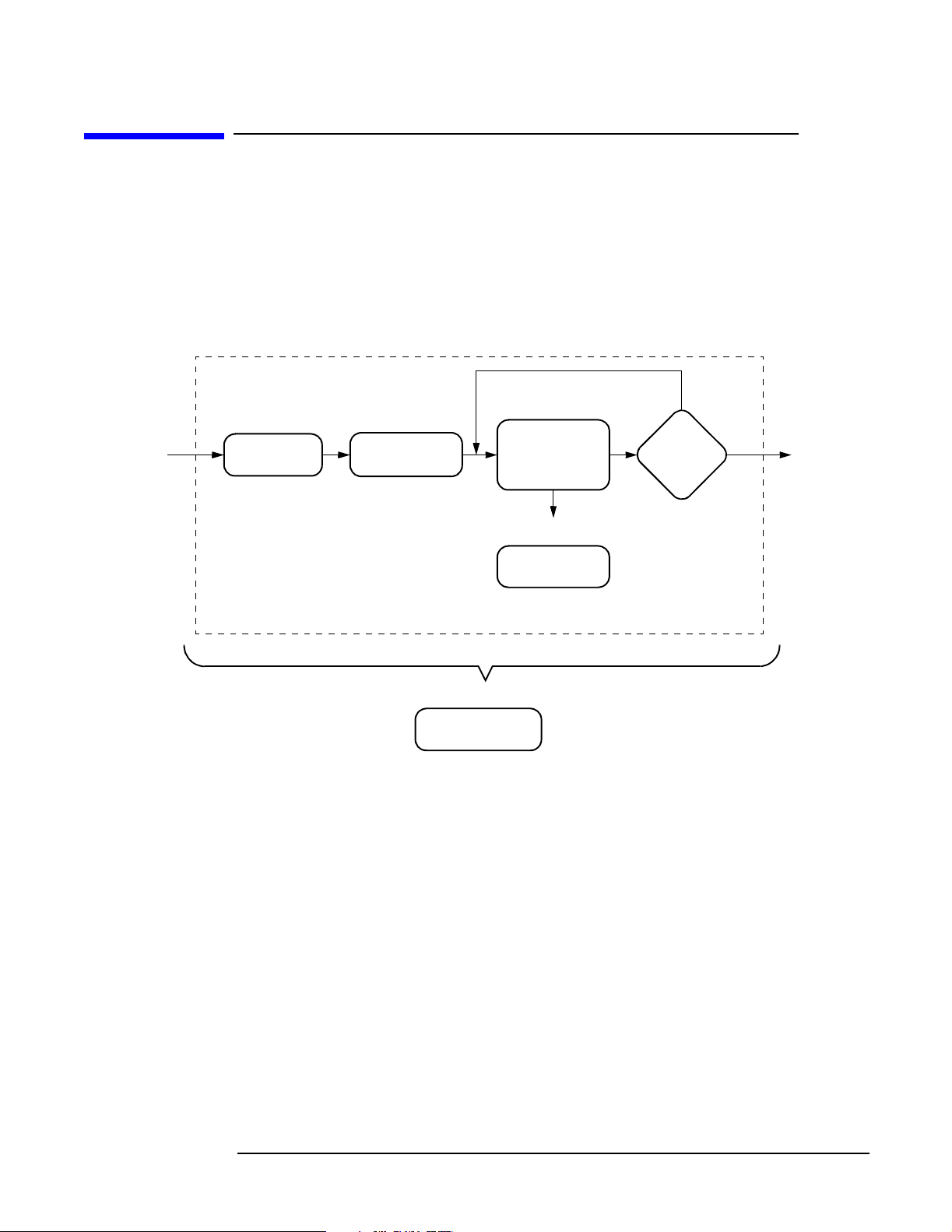
Test Software Operation Overview
Figure 1-1 illustrates the basic steps for Test Software operation. After running the Test
Software, you may repeat a test or you may select another test.
Chapter 4, “Performing Tests,” on page 51, provides step-by-step instructions for each of
the tests. If you have questions, refer to Chapter 5, “Reference,” on page 87 for more
information. If you encounter errors, refer to Chapter 6, “Troubleshooting,” on page 119.
Figure 1-1 Using the Test Software
Chapter 2
Installation
Connection
Troubleshooting
Chapter 6
Chapter 4Chapter 3
Performing
Tests
Chapter 5
Reference
Yes
Run
More
Tests?
No
ExitStart
14
Chapter 1
O:\Manuals\E6385A_Cdma\Book\Prodde sc.fm
Page 14

Product Description
Required Equipment
Required Equipment
Test equipment and other items required for testing are shown in Figure 1-2 and
described in the following paragraphs.
Test Equipment
The Test Software is written specifically to work with the Agilent Technologies 8935
Series E6380A CDMA Base Station Test Set.
Personal Computer (PC)
The Test Set and Test Software support using a PC to control the site via the MSC. This
allows you to dial up or use a telnet connection to log in to the MSC and enter the
maintenance craft shell as you would ordinarily for other cell site operations. The PC is
connected to the Test Set via the SERIAL 9 port. Most PCs with an available serial port
are compatible with the Test Set.
You must install the BTS Laptop Utility program in the PC, so as to relay commands to
the MSC from Test Set, collect test data, log commands sent between the Test Set and
the MSC, and capture screen images.
Cables and Adapters
Various cables and adapters are required. These may be purchased from Agilent
Technologies or from local sources. See “Accessory Kits” on page 17 for information on
optional accessory kits that supply the necessary cables and adapters to connect the Test
Set to the Base Station equipment.
Product Description
Chapter 1
15
Page 15

Product Description
Required Equipment
Figure 1-2 Required Equipment
Test Equipment Required:
TIME
Agilent Technologies 8935 Series E6380A
CDMA Base Station Test Set
Supplied with the Test Software:
E6385A
Lucent
CDMA Base
Station Test
Software
E6385A
Lucent
AMPS Base
Station Test
Software
You Must Supply:
Laptop PC with Internal Modem
Null Modem Cable to Test Set
5182-4794
Blank 1-Mb
SRAM Car d
with battery.
BTS Laptop Utility Program
E6385A Option K01)
(Two diskettes.)
Sample Frequency Plan
(5010-1203)
(One diskette.)
16
AMPS Test
Software Manual
(E6385-90002)
Software Manual
CDMA Test
(E6385-90001)
(This manual.)
J7
-50 dB
-50 dB
-40 dB
-40 dB
J7
J8
J6
-50 dB
J5
-50 dB
J4
-40 dB
J3
-40 dB
J9 J10
J7
J8
J8
J6
J6
-50 dB
J5
J5
-50 dB
J4
J4
-40 dB
J3
J3
-40 dB
J9 J10
J9 J10
Lucent CDMA Base Station
Cables to Connect the Base
Station to the Test System
O:\Manuals\E6385A_Cdma\Book\Prodde sc.fm
Chapter 1
Page 16

Product Description
Optional Equipment
Optional Equipment
Optional test equipment and other optional items are described in the following sections.
GPS Time and Frequency Reference Receiver
The Test Software supports the Symmetricom 58503A GPS Time and Frequency
Reference Receiver for supplying the timebase signal normally taken from the Base
Station equipment.
When connecting to the Base Station SCT modules as the timing reference, the Test
Software uses the signals out of the modules as though those signals are correctly timed
to GPS time to provide the correct PN offset (see “Test Set to GPS Time and Frequency
Reference Receiver Connections” on page 50). If a problem exists in the Base Station
GPS reference or SCT modules, the Base Station PN offset will likely be incorrect.
Use of the 58503A provides a GPS-referenced timing signal that is independent of the
Base Station. This helps isolate problems associated with the Base Station own GPS
reference equipment and/or SCT module(s). An example of this is an “island cell”, where
the Base Station passes performance tests but does not properly interact with adjacent
cells during handoffs.
Product Description
Accessory Kits
Several kits containing selections of accessories for connecting the Test Set to the Base
Station equipment are available from Agilent Technologies. These are described in the
following three sections.
Agilent Technologies E8300A 8935 Base Station Accessory Kit
The Agilent Technologies E8300A 8935 Base Station Accessory Kit (see Table 1-1)
supplies serial cables, RF cables, and adapters required to connect the Test Set for
testing Base Stations.
.
Table 1-1 E8300A Base Station Accessory Kit Contents
Part Part Number Quantity Use
Cable Assembly,
N(M) to N(M), 10-ft.
Cable Assembly,
SMA(M) to BNC(M), 10-ft.
Cable Assembly,
SMA(M) to N(M), 12-ft.
Cable Assembly,
N(M) to N(M), 2-ft.
08921-61010 1 Connects the Base Station TX Antenna Port
to the Test Set RF IN/OUT port.
08921-61021 2 Connects Base Station Even Second clock
and 19.6608-MHz clock to Test Set.
E8300-61002 1 Connects the Base Station TX Test Port to
the Test Set ANT IN port.
E8300-61005 1 Used as the calibration cable for Insertion
Loss test.
Null Modem Cable Assembly,
DB9(F) to DB9(F), 10-ft.
Chapter 1
5182-4794 1 Connects the PC serial port to the Test Set
SERIAL 9 port.
17
Page 17

Product Description
Optional Equipment
Table 1-1 E8300A Base Station Accessory Kit Contents
Part Part Number Quantity Use
Attenuator,
0955-0819 2 Used for cable loss calibration routines.
N(M) to N(F), 6-dB
Adapter,
SMA(F) TO N(M)
Adapter,
1250-1250 2 Used for Base Station TX Test Port Cable
calibration, adapts to a Type N attenuator.
1250-0777 1 Used for joining Type N cables
N(F) to N(F)
Adapter,
TNC(M) to N(F)
1250-2361 1 Used for TNC connections on some Base
Stations.
Velcro Cable Wrap 1400-2157 10 Used for securing and organizing cables for
transporting and during testing.
Verification Guide E8300-90001 1 Used as a checklist for connector kit
contents.
Transit Case E8300-61006 1 Organizes and transports connectors and
cables. Includes spaces for Option 001 parts.
Strain Relief Assembly E8300-61004 2 Reduces strain on connectors from cables.
Strain Relief Application Guide E8300-90005 1 Instructions for using strain relief
assemblies.
Agilent Technologies E8300A Option 001 Accessory Kit
The E8300A Option 001 Accessory Kit (see Table 1-2) includes the additional parts that
are required to run all of the Test Set built-in RF Tools routines. The RF Tools routines
are automated measurements used in cell site maintenance (such as antenna sweeps).
Table 1-2 E8300A Option 001 Accessory Kit Contents
Part Part Number Quantity Use
Cable Assembly,
N(M) to N(M), 2-ft.
8120-8687 2 Used to connect the Test Set to the VSWR
bridge.
VSWR Bridge 0955-0829 1 Used to measure return loss
Termination,
1250-2656 1 Used to terminate transmission lines.
50-ohm, N(M)
Termination,
short, N(M)
Resistive Power Splitter,
1250-2655 1 Used to terminate the DUT port of the
VSWR bridge during return loss tests.
0955-0827 1 Divide a signal in two.
2-way
18
Chapter 1
O:\Manuals\E6385A_Cdma\Book\Prodde sc.fm
Page 18

Product Description
Optional Equipment
Agilent Technologies E6554A 8935 RF Tools Hardware Accessory Kit
NOTE If you do not purchase the Agilent Technologies E8300A Accessory Kit, you may order
the Agilent Technologies E6554A RF Tools Hardware Accessory Kit to provide all of the
required connectors, cables, and accessories to run the RF Tools tests.
The Agilent Technologies E6554A 8935 RF Tools Hardware Accessory Kit (see Table 1-3)
contains the equipment necessary to run the “Return Loss Measurement” on page 82
and to run the RF Tools ROM programs that reside in the Test Set. Refer to the Agilent
Technologies 8935 CDMA Cellular/PCS Base Station Test Set Reference Guide for more
information about the RF Tools program.
Table 1-3 E6554A 8935 RF Tools Hardware Accessory Kit
Part Part Number Quantity Use
Cable Assembly,
N(M) to N(M), 2-ft.
8120-8687 2 Used to connect the Test Set to the VSWR
bridge.
VSWR Bridge 0955-0829 1 Used to measure return loss
Termination,
1250-2656 1 Used to terminate transmission lines.
50-ohm, N(M)
Termination,
short, N(M)
Resistive Power Splitter,
1250-2655 1 Used to terminate the DUT port of the VSWR
bridge during return loss tests.
0955-0827 1 Divides one signal into two signals.
2-way
Adapter,
1250-0077 2 Connects BNC cables to type N connections.
BNC(M) to N(F)
Attenuator,
N(M) to N(F), 6-dB
0955-0826 2 Used during cable loss, insertion loss, and
return loss tests.
Transit Case E6554-61004 1 Organizes and safely transports kit contents.
Verification Guide E6554-9001 1 Used as a checklist for accessory kit contents.
Product Description
Chapter 1
19
Page 19

Product Description
Getting Help, Test Software Upgrades, and Training
Getting Help, Test Software Upgrades, and Training
For instrument servicing, see the Agilent Technologies 8935 Series E6380A CDMA Test
Set Assembly Level Repair Guide.
For application assistance, call the Application Hotline (1-800-922-8920, USA and
Canada only).
For information about Test Software upgrades and hands-on training, contact the local
Agilent Technologies sales engineer.
20
Chapter 1
O:\Manuals\E6385A_Cdma\Book\Prodde sc.fm
Page 20

2 Installation
This chapter describes the processes required to load and run the Test Software, connect
the equipment, and make initial settings to configure the Test Set and the Test Software.
You must complete the procedures in this chapter before attempting measurements with
the Test Software.
Installation
Chapter 2
21
Page 21

Installation
Overview
Overview
The procedures included in this chapter are as follows:
1. “Loading and Running the Test Software” on page 23.
2. “Navigating the Test Software” on page 25
3. “Operating the BTS Laptop Utility Program” on page 27.
NOTE
BTS Laptop Utility program operation requires the use of a personal computer (PC)
(usually a laptop PC). The use of a PC is not an absolute requirement, but the test
examples in Chapter 4, “Performing Tests,” on page 51 use a PC to control the cell
site via the Mobile Switching Center (MSC). The Test Software also supports testing
without PC control. If you elect not to use a PC with the Test System, skip the section
that describes using the BTS Laptop Utility program and refer to “Testing without
MSC Control” on page 117 for a summary of differences when running without the
PC.
4. “Connecting the PC to the Test Set and the MSC” on page 32.
5. “Determining the Test Set to Site Equipment Connections” on page 36.
6. “Configuring the Test Software” on page 38.
7. “Establishing a Connection with the MSC for Testing” on page 43.
22
Chapter 2
O:\Manuals\E6385A_Cdma\Book\Install.fm
Page 22

Loading and Running the Test Software
Locate the PC card labeled “Agilent Technologies E6385A Lucent CDMA Base Station
Test Software” and follow the steps outlined in Figure 2-1 and Figure 2-2.
Figure 2-1 Loading and Running the Test Software
Turn the power on. (The power switch
1
is located above the power cord
Wait until the first test
2
screen is displayed
(about 45 seconds).
connection on the right-side panel.)
Installation
Loading and Running the Test Software
- - - -
Menu
Insert the Test Software card.
3
Press
4
Preset.
Installation
Chapter 2
23
Page 23

Installation
Loading and Running the Test Software
Figure 2-2 Loading and Running the Test Software (continued)
Press the SOFTWARE Menu key to display the
5
Lucent CDMA Tests Main Menu screen.
Scroll to Card
7 8
and select it.
Scroll to Select Procedure Locat ion:
6
and select it.
Scroll to Select Procedure Filena me :
and select it.
Scroll to Choices:
and select t he Procedur e name.
DEMO
LCDMA
Scroll to Run Test
109
and select it. The Test Software will load.
Loading Time:
First time:
approximately
20 seconds.
After first time:
approximately
8 seconds.
24
Chapter 2
O:\Manuals\E6385A_Cdma\Book\Install.fm
Page 24
Navigating the Test Software
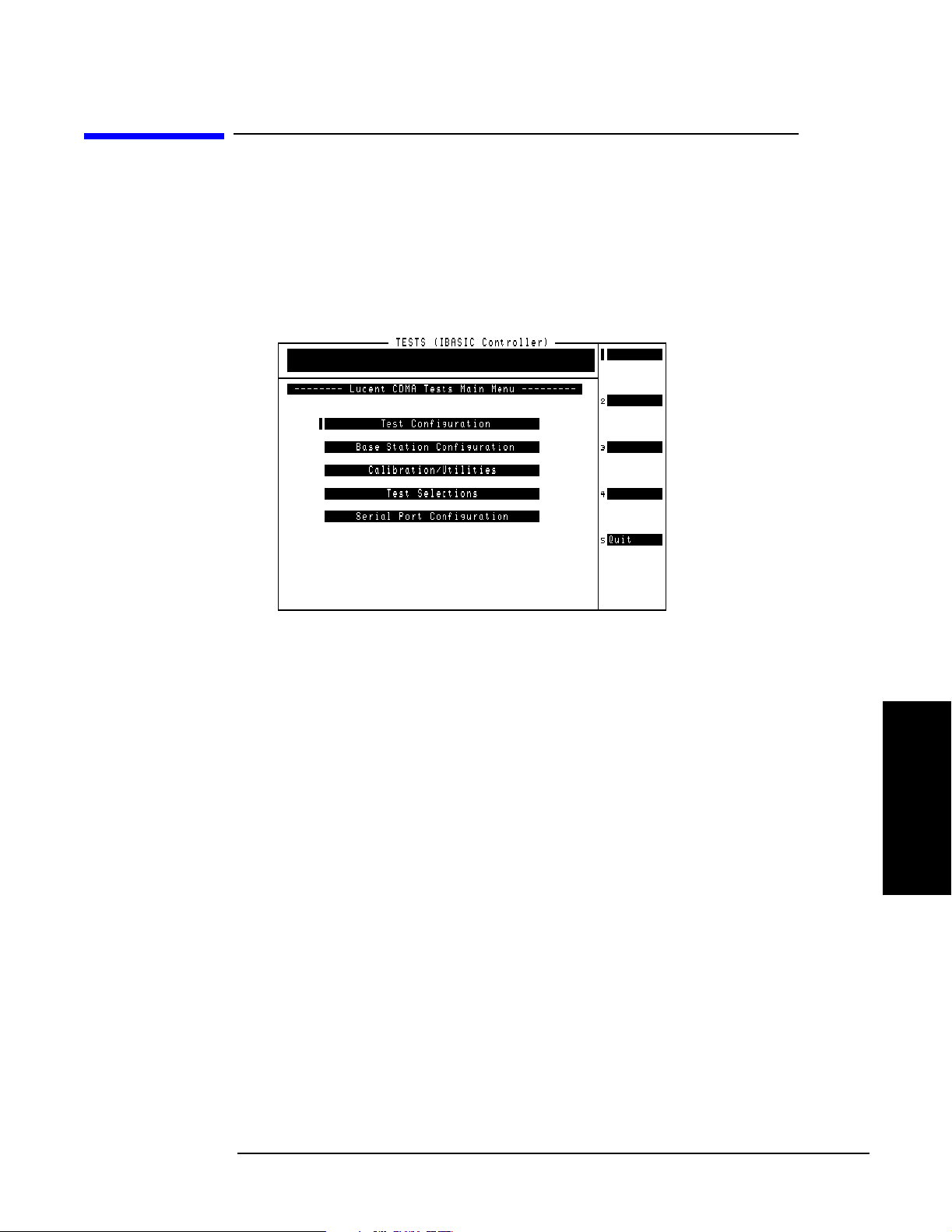
After the Test Software has loaded, the Lucent CDMA Tests Main Menu screen will
appear on the Test Set display (see Figure 2-3).
Configuration operations, test utilities, and tests are grouped into sub-menus. Turn and
press the knob to access the desired sub-menu.
Figure 2-3 Lucent CDMA Tests Main Menu Screen
Installation
Navigating the Test Software
Main Menu Functions
• Test Configuration – Define test information used by all tests; such as identifying
the timing reference signal source, measurement port selection, number of averages,
Walsh code power units, cable losses, and Base Station TX Test Port coupling factor.
• Base Station Confi gurati on – Enter the specific cell site and Base Station
information that the Test Software requires to control the Base Station when
communicating with the MSC during tests (after configuring the PC and verifying its
operation).
• Calibration/Utilit ies – Access procedures used to ensure optimal calibration of
the Test Set and test cables.
• Test Selections – Access the available tests.
• Serial Port Config uratio n – Access routines used to define the serial port
communication settings for interfacing with the PC serial port.
Installation
Chapter 2
25
Page 25
Installation
Navigating the Test Software
Changing Settings and Using USER Keys
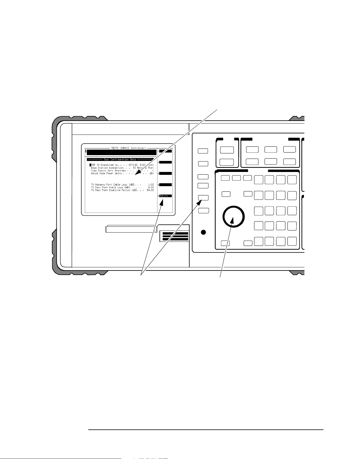
See Figure 2-4 for information on settings and USER keys.
Figure 2-4 Settings and USER Keys
Menu Selections
Some Menu selections are entry fields. When one of these is selected, a highlighted area appears
and you may key in a valu e using the DATA keys, or r otate the knob to c hange th e value in the fie ld.
When the desired value is set, press the knob or the Enter key.
k1
k2
k3
k4
USER Keys and Fields
The USER Keys (k1 - k5) correspond to fields 1-5 on
the right side of the test sc reen. These keys a re used for
navigating through menus and for m ak ing s ele cti ons . In
many lower-level menus, a “Return” key is provided to
display the previous sc reen.
k5
Knob
The knob controls the cursor position on the
display and is used sometimes to make
numeric entries. Pressing the knob has the
same effect as pressing the Enter key.
26
Chapter 2
O:\Manuals\E6385A_Cdma\Book\Install.fm
Page 26

Installation
Operating the BTS Laptop Utility Program
Operating the BTS Laptop Utility Program
The Test Software can control the cell site to perform tests in much less time than would
be required under manual control. In order to control the Base Station, you may use a
PC and modem to dial the MSC directly, or you may use a PC to establish a telnet
connection to the MSC. The BTS Laptop Utility program running on that PC allows the
Test Set to communicate with the MSC through the PC for automatic testing.
NOTE
The method of site control described in this section is optional, but is highly desirable
when possible. If you elect to use other means of controlling the site equipment, some
information about the Base Station is still required. Enter the appropriate information
in the Base Station Configuration Menu screen (see “Base Station Configuration” on
page 41), skip the rest of this chapter, and start testing (see Chapter 4, “Performing
Tests,” on page 51). See also “Testing without MSC Control” on page 117.
If you elect not to control the MSC using a PC, you may skip the rest of this chapter. Note
however, that the procedures in Chapter 4, “Performing Tests,” use a PC for site control.
The BTS Laptop Utility program is shipped with the Test Software on two separate
3.5-inch diskettes. You must install the BTS Laptop Utility program on the PC to
communicate with the MSC. The utility program also provides several other helpful
functions.
The BTS Laptop Utility program provides the following window functions:
• Switch Terminal – A window that: 1) works with the PC internal modem to dial into
the MSC, or with the PC and a telnet connection to the MSC, and 2) displays the
information sent to and from the MSC.
• Test Set Terminal – A window in which you may view commands sent by the Test
Set to the MSC.
• Other Data – This window is not used in CDMA testing.
• Test Results – A window in which automated test results are displayed and may be
saved for later use.
Installation
Chapter 2
• Test Set Screen Capture – A window in which to capture screen images and save
each as a bit mapped image. This is very helpful when using the Test Set spectrum
analyzer or when you wish to capture some other screen. Note that IBASIC program
operation must be paused first, by pressing the Pause/Continue key, to print any of
the TESTS screens used for automated testing.
For more information on the windows in the above list, see “BTS Laptop Utility Program
Windows” on page 105. For additional information on using the BTS Laptop Utility
program after installation, refer to the online Help topics included with that program.
27
Page 27
Installation
Operating the BTS Laptop Utility Program
System Requirements for BTS Laptop Utility Program
If the PC does not meet the following minimum system requirements, this could cause
erratic operation and longer test times.
• 166-MHz Pentium Processor
• 16 megabytes of RAM
• Windows® 95, Windows 98, or Windows NT 4.0 (Intel based)
• Available RS-232 serial port
• Internal modem
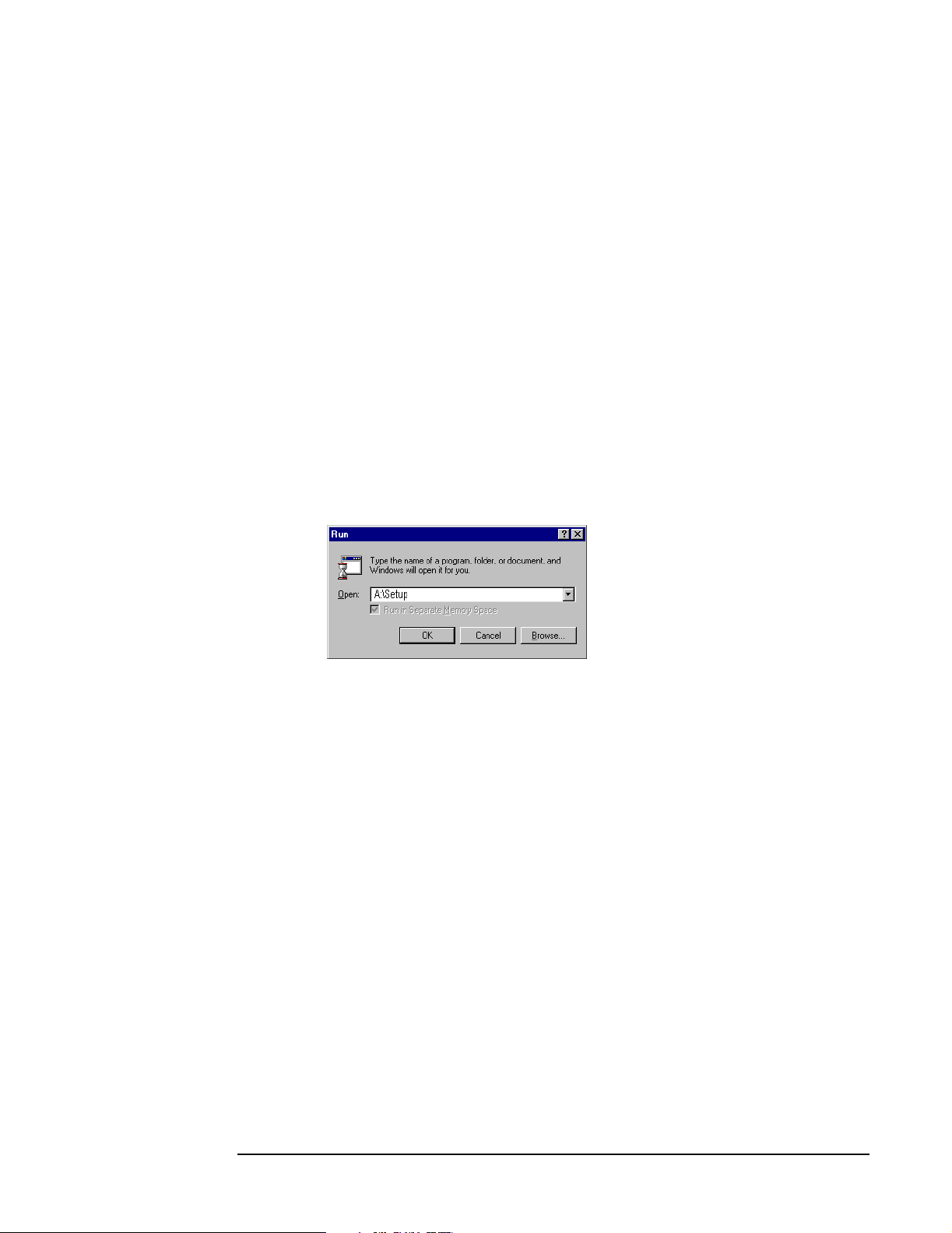
Installing the BTS Laptop Utility Program
The BTS Laptop Utility program comes compressed on two install diskettes for easy
setup on the PC. Simply insert the first diskette into the drive, select Start then Run,
then type A:\Setup. The install shield will lead you through the installation process (see
Figure 2-5).
Figure 2-5 Installing the BTS Laptop Utility Program
28
Chapter 2
O:\Manuals\E6385A_Cdma\Book\Install.fm
Page 28

Installation
Operating the BTS Laptop Utility Program
Configuring the Test Set and PC Serial Ports for Communication with the Test Set
After installing the BTS Laptop Utility program, you must configure the Test Set and PC
serial ports to communicate with the Test Set.
Configure the serial ports as follows:
Step 1. On the Test Set, determine and record the Test Set SERIAL 9 port data transfer (baud)
rate as follows:
• Load and run the Test Software (see“Loading and Running the Test Software” on
page 23). The Test Software will display the Lucent CDMA Tests Main Menu screen.
• Select the Serial Port Configur ation field. The Test Software will display the
Serial Port Configuration Menu screen.
• Select the Serial 9 Po rt Config uration field. The Test Software will display the
Serial 9 Port Configuration Menu screen.
• Select and set the following Serial 9 Port Configuration Menu fields as appropriate
for operation with the BTS Laptop Utility program.
NOTE
NOTE
— Baud Rate – Select the field and then select a value from the drop-down C hoices:
list to match the Baud Rate setting in the BTS Laptop Utility program Preferences,
Comm Port Setup drop-down window. The default value is 9600. However, the Test
Software will operate more quickly at 19200, so it is recommended that you change
the value to 19200.
IMPORTANT: If you select a baud rate greater than 19200, the PC must remain
connected to the Test Set or the Test Set will not operate properly, and might
appear to be locked up.
— Data Length – Select the field and select 8 from the drop-down Cho ices: list.
— Parity – Select the field and select None from the drop-down Choices: list.
Installation
— Stop Length – Select the field and select 1 from the drop-down Cho ices: list.
— Flow Control – The default is None. If it is not set to the default, select the field and
select None from the drop-down Choices: list.
For optimum performance, use the following settings for Flow Control:
For baud rates ≤ 19200, Flow Control should be set to None.
For baud rates >19200, Flow Control should be set to Hardware.
Chapter 2
Step 2. On the PC, determine and record the PC serial COM port designation (for example,
COM1) from the Windows Device Manager Ports (COM & LPT) selection.
Step 3. On the PC, invoke the BTS Utility program. The BTS Utility program tool bar will
appear on the PC display.
Step 4. Select SW, TS, OD, or TR (any one will do) from the BTS Laptop Utility program tool
bar.
29
Page 29

Installation
Operating the BTS Laptop Utility Program
Step 5. Select Preferences, then Comm Port Setup.
Step 6. On the Comm Port Setup drop-down window, in the Test Set - Port list, select the port
that the PC will use to communicate with the Test Set, as determined in Step 2.
Step 7. On the Comm Port Setup drop-down menu, in the Test Set - Baud Rate list, select
the data transfer rate at which the PC will communicate with the Test Set, as
determined in Step 1. This value will not automatically adjust during the session. The
recommended baud rate for the Test Set is 19200.
30
Chapter 2
O:\Manuals\E6385A_Cdma\Book\Install.fm
Page 30

Installation
Operating the BTS Laptop Utility Program
Configuring the PC to Communicate with the MSC
After installing the BTS Laptop Utility program, if you are using the utility program to
communicate with the MSC, you must configure the PC to do so. This may be done in
either of two ways: 1) by using modem to dial the MSC directly, or 2) by using a telnet
connection. The telent connection may be either a dial-up Internet connection, or a direct
Internet connection. The dial-up Internet connection would use the PC modem; the
direct Internet connection would use a PC LAN (the most common of which is ethernet).
Modem Connection
If you elect to use a modem connection, configure the MSC connection as follows:
Step 1. On the PC, determine and record the PC modem port COM designation (for example,
COM2) from the Windows Device Manager Modem selection.
Step 2. On the PC, invoke the BTS Laptop Utility program. The BTS Laptop Utility program
tool bar will appear on the PC display.
Step 3. Select SW, TS, OD, or TR (any one will do) from the BTS Laptop Utility program tool
bar.
Step 4. Select Preferences, then Comm Port Setup.
Step 5. On the Comm Port Setup drop-down menu, in the Switch - Port list, select the PC
COM port assigned to the PC modem, as determined in Step 1.
If the modem port is already in use, the Test Software will display a message stating that
a device already has control of that port. The most common cause is a communication
program running in the PC background. Close the other program and reselect the
required COM port.
Step 6. On the Comm Port Setup drop-down menu, in the Switch - Baud Rate list, select the
data transfer rate at which the PC will communicate with the modem. Note that this is
not the rate at which the modem will communicate with the MSC. Most modems
negotiate at the start of the session with the modem on the other end of the line for the
best data transfer rate. A typical setting is 57600.
Telnet Connection
If you elect to use a telnet connection, configure the MSC connection as follows:
Step 1. On the PC, invoke the BTS Laptop Utility program. The BTS Laptop Utility program
tool bar will appear on the PC display.
Step 2. Select SW, TS, OD, or TR (any one will do) from the BTS Laptop Utility program tool
bar.
Step 3. Select Preferences, then Comm Port Setup.
Step 4. On the Comm Port Setup drop-down menu, in the Switch - Port list, select Telnet.
Installation
Chapter 2
Step 5. On the Comm Port Setup drop-down menu, the Switch - Baud Rate list is not active
for a telnet connection. Make no selection.
31
Page 31
Installation
Connecting the PC to the Test Set and the MSC
Connecting the PC to the Test Set and the MSC
The following sections describe the processes for connecting the PC to both the Test Set
and the MSC.
Connecting the PC to the Test Set
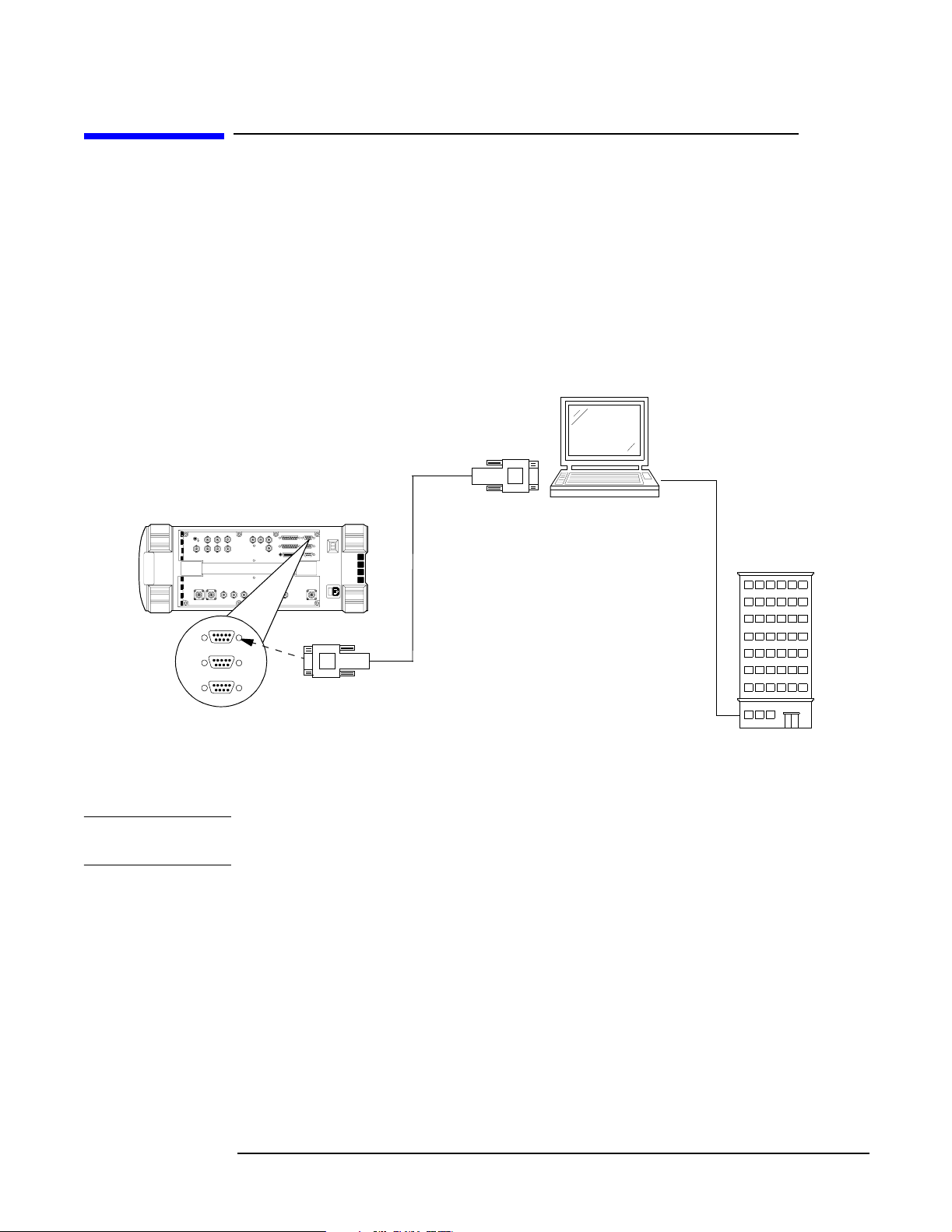
Connect a null modem cable (DB9 to DB9) from the Test Set to the COM port of the PC
as shown in Figure 2-6.
Figure 2-6 Test Set to PC and PC to MSC Connection
COM DB9
Connector
Test Set Side Panel
Laptop PC
NOTE
MSC
SERIAL 9
SERIAL 10
SERIAL 11
Null Modem Cable
Phone Line
or
LAN Connection
SERIAL 9 Port
DB9 Connector
At this point, you should be able to communicate with the Test Software.
To test the connection, configure the test set as follows, then attempt a screen capture.
The screen capture function is inoperable while the Test Software is running. The Test
Software must be paused.
Step 1. If the Test Software is running (a star appears in the upper right-hand corner of the
display), press the
Step 2. Press the Test Set
Pause/Continue key to pause it.
Shift key. then the Inst Config (I/O Config) key. The Test Set will display
the I/O CONFIGURE screen.
Step 3. Select the Serial_9 In field and press the knob to toggle the setting to Inst
(underlined).
Step 4. Press the Test Set
Shift key, then the Print (Printer Config) key. The Test Set will display
the PRINTER CONFIGURE screen.
Step 5. Select the Model field and select DeskJet from the drop-down Choices: list.
32
O:\Manuals\E6385A_Cdma\Book\Install.fm
Chapter 2
Page 32

Installation
Connecting the PC to the Test Set and the MSC
Step 6. Select the Printer Port field and select Serial 9 from the drop-down Ch oices: list.
Step 7. With the cable connections complete and BTS Laptop Utility program running on the
PC, press the Test Set
Test Set Screen Capture window on the PC screen.
Print key. The currently-displayed screen should appear in the
Connecting the PC to the MSC
After installing BTS Laptop Utility program on the PC, you must establish the
connection between the PC and the MSC. This may be accomplished using either a direct
dial-up modem connection or a telnet connection. These methods are described in the
following sections.
Connect the PC to the MSC via a phone line or LAN connection as shown in Figure 2-6
Testing a Direct-Dial Modem Connection
The PC modem must be connected to a phone line capable of connecting to the MSC. If no
phone line is available at the Base Station, a wireless phone with a properly configured
wireless-capable modem will suffice.
Test a modem connection as follows:
Step 1. From the BTS Laptop Utility program tool bar, select SW.
Step 2. In the Switch Terminal window, select Dial.
Step 3. In the drop-down Dial window, enter the MSC phone number, then select OK (see
Figure 2-7).
Step 4. When prompted in the Switch Terminal window by the MSC, enter the same
commands that you would use in your usual communication program to log in to the
ECP. Once logged into the ECP, enter the maintenance craft shell. When you have
finished, a command prompt will appear, which indicates that the MSC is waiting for the
next command.
If you intend to start testing the Base Station soon, leave the MSC connection enabled. If
some time will elapse before you start testing, log off from the MSC, and click on the
Hangup/Disconnect (HU) button in the Switch Terminal window.
Installation
Chapter 2
33
Page 33

Installation
Connecting the PC to the Test Set and the MSC
Figure 2-7 Dialing and Logging Into the MSC Using the Switch Terminal Window
Select Dial, and enter the
phone number for the MSC.
After the MSC answers,
enter your login and password
as usual to enter the
Maintenance Craft Shell.
34
Chapter 2
O:\Manuals\E6385A_Cdma\Book\Install.fm
Page 34

Installation
Connecting the PC to the Test Set and the MSC
Testing a Telnet Connection
The telnet connection uses the Internet to connect to the MSC. You may use either a
direct connection (using a LAN such as ethernet) or a dial-up connection (using the PC
modem).
Test a telnet connection as follows:
Step 1. Use the PC to establish a telnet connection to the MSC according to your preferred
method (direct or dial-up).
Step 2. From the BTS Laptop Utility program tool bar, select SW.
Step 3. In the Switch Terminal window, select Dial.
Step 4. In the drop-down Dial window, enter the IP address as the phone number, then select
OK (see Figure 2-7).
Step 5. When prompted by the MSC in the Switch Terminal window, enter the same
commands that you would use in your usual communication program to log in to the
ECP. Once logged into the ECP, enter the maintenance craft shell. When you have
finished, a command prompt will appear, which indicates that the MSC is waiting for the
next command.
If you intend to start testing the Base Station soon, leave the MSC connection enabled. If
some time will elapse before you start testing, log off from the MSC, and click on the
Hangup/Disconnect (HU) button in the Switch Terminal window.
Installation
Chapter 2
35
Page 35

Installation
Determining the Test Set to Site Equipment Connections
Determining the Test Set to Site Equipment
Connections
At this point in the process, you must decide the clock reference, the Test Set port, and
the Base Station port to be used in testing. At appropriate points in a test sequence, the
Test Software will display prompts directing you to make connections. For details on the
required connections, see Chapter 3, “Connections,” on page 45.
Which Clock to Use – SCT Clock or External Reference?
If you elect to use the SCT clock signal, connect and enable it as follows:
Step 1. Connect the clock signals (19.6608-MHz and even-second) and transmitter output to the
Test Se t (see “Test Set to Base Station Connections” on page 46).
Step 2. Set the TST CLK switch on the SCT module to ON to enable the Base Station clock
signals.
If you elect to use a separate GPS reference instead of the cell site clocks, see “Test Set to
GPS Time and Frequency Reference Receiver Connections” on page 50.
CAUTION
Which Test Set Port to Use – ANT IN or RF IN/OUT?
The Test Set ANT IN port is only used for very low signal levels ≤ 60 milliwatts (17.78
dBm). Therefore, to prevent damage to the Test Set, never connect this port directly to the
Base Station TX Antenna Port. This port is typically connected to the Base Station TX
Test Port.
The Test Set RF IN/OUT port is for CDMA signals of
signals of ≤75 watts. This is the only port on the Test Set that you should connect directly
to the Base Station TX Antenna Port. If power levels from the Base Station exceed the
specification of the port, use an appropriate signal attenuator.
watts or continuous wave
≤15
Which Base Station Port to Use – TX Test or TX Antenna?
Testing may be performed while connected to either the Base Station Test Port or the
Base Station Antenna Port. Testing at the Antenna Port involves taking the Base
Station out of service. The choices are described in the following sections.
In-Service Testing Using the Base Station TX Test Port
The Base Station TX Test Port signal is derived from the directional coupler that is
connected between the Linear Amplifier and the Base Station TX Antenna Port (see
Figure 2-8). This allows you to make measurements on an active Base Station without
disconnecting the transmit antenna and interrupting service. You must enter a value for
the coupling factor (loss) through the directional coupler to compensate power
measurements (see “Test Configuration” on page 39). Coupling factors are typically 40
to 70 dB, but might vary, depending on the Base Station design.
36
Chapter 2
O:\Manuals\E6385A_Cdma\Book\Install.fm
Page 36

Determining the T est Set to Site Equipment Connections
Figure 2-8 Transmitter Output Path Simplified Diagram
Installation
NOTE
Antenna
TX Antenna Port
Base Station
Linear
Amplifier
Directional
Coupler
TX Test Port
Coupling Factor is the loss through the
directional coupler to the TX Test port.
If you are uncertain of the exact coupling factor, the Test Software contains a utility to
measure the coupling factor (see “TX Test Port Calibration Test” on page 77).
If you are uncertain of the Specified Output Power for the transmitter at the Base
Station TX Antenna Port, the Test Software must measure the power to calculate the
coupling factor. This requires that you take the Base Station out of service to connect the
Test Set directly to the Base Station TX Antenna Port during the calibration routine.
One disadvantage to using the Base Station TX Test Port to make measurements is the
possibility that its coupler is malfunctioning and therefore will cause erroneous
measurements. If TX power measurements fail by a large amount, but you suspect the
actual transmitted power is correct, take the Base Station out of service and make
measurements directly at the Base Station TX Antenna Port to verify the failing
reading. If the Test Software is correctly configured, TX power measurements using the
Base Station TX Test Port and TX Antenna Port should not differ significantly.
Out-of-Service Testing Using the Base Station TX Antenna Port
Disconnecting a TX antenna feed line and connecting the Test Set to the Base Station TX
Antenna Port (see Figure 2-8) requires that you first take the Base Station out of service
(disable call processing and turn off all transmissions to that TX Antenna Port).
The Base Station may be taken out of service (and turned back on to make
measurements) in two ways:
1. Access the MSC using a PC and the BTS Laptop Utility program to control the Base
Station through its maintenance software.
2. Call the MSC and have switch personnel control the Base Station for you.
One benefit of testing directly at the Base Station TX Antenna Port is the confidence
that the measurement will reflect the true output power of the Base Station at the point
at which the antenna feed line connects to the Base Station. This verifies the operation
of the full transmission path inside the Base Station. It also provides an opportunity to
perform transmission line and antenna testing while the antenna is disconnected from
the Base Station.
Installation
Chapter 2
37
Page 37

Installation
Configuring the Test Software
Configuring the Test Software
If the Test Software is not loaded and running, see “Loading and Running the Test
Software” on page 23.
After the Test Software has loaded and is running, the Test Software will display the
Lucent CDMA Tests Main Menu screen (see Figure 2-9). Configuration operations, test
utilities, and tests are grouped into the listed sub-menus. Turn and press the knob to
access the desired sub-menu.
Figure 2-9 Lucent CDMA Tests Main Menu Screen
38
Chapter 2
O:\Manuals\E6385A_Cdma\Book\Install.fm
Page 38

Test Configuration
Before the Test Software can perform automated Base Station testing, it must have
available certain information regarding test conditions. Supply this information on the
Test Configuration Menu screen.
Configure the test as follows:
Step 1. Select the Test Configuration field. The Test Software will display the Test
Configuration Menu (see Figure 2-10).
Figure 2-10 Specifying Test Configuration Information
Installation
Configuring the Test Software
Step 2. Select the REF IN Connected to field and select the source of the input signal from the
drop-down Choices: list. The selections are: SCT (J2) [16X C hip] (typically, the
19.6608-MHz clock from one of the cell site SCT modules) or GPS [10 MHz], which is
from a GPS receiver.
Step 3. Select the Base Station Connection field and select the test port to be used in the
measurement from the drop-down Ch oices : list. The selections are: TX Antenna Port
(which supplies the transmitter power directly to the antenna) or TX Test Por t (which
comes from a directional coupler in the transmitter output).
Step 4. Select the Code Domain Average s field, rotate the knob to the desired value, then press
the knob to select it. Choose this value carefully. More data samples when averaging
measurements will increase testing time, but will reduce the effects of small level
changes, thus producing higher consistency and providing a higher confidence level for
the test results.
Step 5. Select the Walsh Code Power Units field and select the units in which the Walsh code
power will be displayed from the drop-down Choices: list. The selections are: dBt, dBm,
and Watts. The unit “dBt” refers to the power of a Walsh code relative to the total
measured channel power. The units dBm and Watts are measurements of the absolute
power for a Walsh code.
Installation
Chapter 2
39
Page 39

Installation
Configuring the Test Software
Step 6. Select the TX Antenna Port Cable L oss [dB] field, rotate the knob to the loss value
for the cable that you connect from the Test Set RF IN/OUT port to the Base Station TX
Antenna port, and press the knob to select it. If you are uncertain of the cable loss value,
run the “TX Antenna Port Cable Calibration Test” on page 75 to measure and enter the
value automatically.
Step 7. Select the TX Test Port Cabl e Loss [dB] field, rotate the knob to the loss value of the
cable that you connect from the Test Set ANT IN port to the Base Station TX Test Port,
and press the knob to select it. If you are uncertain of the cable loss value, run the “TX
Test Port Cable Calibration Test” on page 76 to measure and enter the value
automatically.
Step 8. Select the TX Antenna P ort Coupli ng Factor [dB] field, rotate the knob to the value
of the loss through the directional coupler used to provide the transmitter signal to the
Base Station TX Test Port, and press the knob to select it. The Test Software will use this
value to calculate the transmitter true power output without the requirement for
disconnecting the transmit antenna from the TX Antenna port. If you are uncertain of
the coupling factor value, run the “TX Test Port Calibration Test” on page 77 to measure
and enter this value automatically.
40
Chapter 2
O:\Manuals\E6385A_Cdma\Book\Install.fm
Page 40

Base Station Configuration
Before the Test Software can control the Base Station, it must be able to notify the MSC
as to the cell site and BBA to test. The Test Software also requires a value as to the
amount of power to be measured. You must supply this information on the Base Station
Configuration Menu screen.
Configure the Base Station as follows:
Step 1. Select the Base Station C onfigurat ion field. The Test Software will display the Base
Station Configuration Menu (see Figure 2-11).
Figure 2-11 Specifying Base Station Configuration Information
Installation
Configuring the Test Software
Step 2. Select the Base Station Type field and select the type of Base Station to be tested from
the drop-down Choices: list: PCS Minicell or Auto plex Seri es II.
Step 3. Select the ECP Number field, rotate the knob to the number for the ECP that controls the
cell site to be tested, and press the knob to select it.
Step 4. Select the Cell Site Number field, rotate the knob to the number for the cell site to be
tested, and press the knob to select it.
Step 5. Select the BBA Under Test field, rotate the knob to the number of the BBA to be tested,
and press the knob to select it.
Step 6. Select the BCR Attenuation Level field, turn the knob to the value that is to be used to
control Base Station power by the MSC when measuring transmitted power, and press
the knob to select it. This value will vary according to the Base Station type (model) and
geographic location (see “Transmit Power Calibration Test (Autoplex Series II)” on page
56 for more information).
Installation
Chapter 2
41
Page 41

Installation
Configuring the Test Software
Step 7. Select the Specified Output Power [Watts] field, turn the knob to the expected
output power at the TX Antenna port (foam jumper) or at the Base Station TX Test Port
after subtracting the coupling factor, and press the knob to enter it. This value must be
set for both manual and automated testing.
NOTE
This output power setting is for a pilot channel only signal. It is affected by: 1) the
number of channel elements that are active, and 2) the BCR attenuation setting and
digital gain unit (DGU) settings for the pilot, sync, paging, and traffic channels in the
translation table. Use the value specified by Lucent for testing power.
Step 8. Select the RF Channel Standard field and select from the drop-down Choices: list the
standard to be used when you enter a channel number: N. Amer ican Cell ular,
N. American PCS, or Korean PCS P 4.
Step 9. Select the Channel Number field, rotate the knob to the number for the CDMA channel
on which the Base Station is transmitting, and press the knob to select it.
Step 10. Select the PN Offset field, rotate the knob to the value for the cell site, and press the
knob to enter it. If you are uncertain of the offset, run the “PN Offset Search Test” on
page 79) to find and enter the number automatically.
Step 11. Select the Send Control Commands to MSC field.
If you wish to use automated control of the cell site, press the knob to toggle it to YES. If
you toggle it to YES, the Channel Eleme nts to Te st field will appear on the next line.
Rotate the knob to the desired number between 0 and 55, and press the knob to select it;
or use the DATA ENTRY keys to enter the number and either press the knob or press
Enter key.
the
If you wish to use manual control of the cell site, press the knob to toggle it to No.
Step 12. Press the
k5 (Return) key to return to the Lucent CDMA Tests Main Menu screen.
42
Chapter 2
O:\Manuals\E6385A_Cdma\Book\Install.fm
Page 42

Establishing a Connection with the MSC for Testing
Establishing a Connection with the MSC for Testing
If it is not set up already, you must establish the connection between the PC and the
MSC. This may be accomplished using either a direct dial-up modem connection or a
telnet connection. These methods are described in the following sections.
Connect the PC to the MSC via a phone line or LAN connection as shown in Figure 2-6
on page 32.
Establishing a Direct-Dial Modem Connection
The PC modem must be connected to a phone line capable of connecting to the MSC. If no
phone line is available at the Base Station, a wireless phone with a properly configured
wireless-capable modem will suffice.
Test a modem connection as follows:
Step 1. From the BTS Utility program tool bar, select SW.
Step 2. In the Switch Terminal window, select Dial.
Installation
Step 3. In the drop-down Dial window, enter the MSC phone number, then select OK (see
Figure 2-7 on page 34).
Step 4. When prompted by the MSC in the Switch Terminal window, enter the same
commands that you would use in your usual communication program to log in to the
ECP. Once logged into the ECP, enter the maintenance craft shell. When you have
finished, a command prompt will appear, which indicates that the MSC is waiting for the
next command.
Establishing a Telnet Connection
The telnet connection uses the Internet to connect to the MSC. You may use either a
direct connection (using a LAN such as ethernet) or a dial-up connection (using the PC
modem).
Test a telnet connection as follows:
Step 1. Use the PC to establish a telnet connection to the MSC according to your preferred
method (direct or dial-up).
Step 2. From the BTS Utility program tool bar, select SW.
Step 3. In the Switch Terminal window, select Dial.
Step 4. In the drop-down Dial window, enter the IP address as the phone number, then select
OK (see Figure 2-7 on page 34).
Installation
Chapter 2
Step 5. When prompted by the MSC in the Switch Terminal window, enter the same
commands that you would use in your usual communication program to log in to the
ECP. Once logged into the ECP, enter the maintenance craft shell. When you have
finished, a command prompt will appear, which indicates that the MSC is waiting for the
next command.
43
Page 43

Installation
If You Noticed Problems
If You Noticed Problems
If you were unable to load and run the Test Software, make the required entries, or
encountered error messages, refer to Chapter 6, “Troubleshooting,” on page 119 for help.
44
Chapter 2
O:\Manuals\E6385A_Cdma\Book\Install.fm
Page 44

3 Connections
This chapter shows the connections between the Test Set and the Base Station and
connections between the Test Set and the GPS Time and Frequency Reference Receiver.
The Test Software will display a screen prompt whenever a connection or a change in
connections is required.
Connections
Chapter 3
45
Page 45
Connections
Test Set to Base Station Connections
Test Set to Base Station Connections
Figure 3-1, Figure 3-2 on page 47, Figure 3-3 on page 48, and Figure 3-4 on page 49 show
connections between the Base Stations and the Test Set. All of the setups use the SCT
module clocks for the Test Set reference.
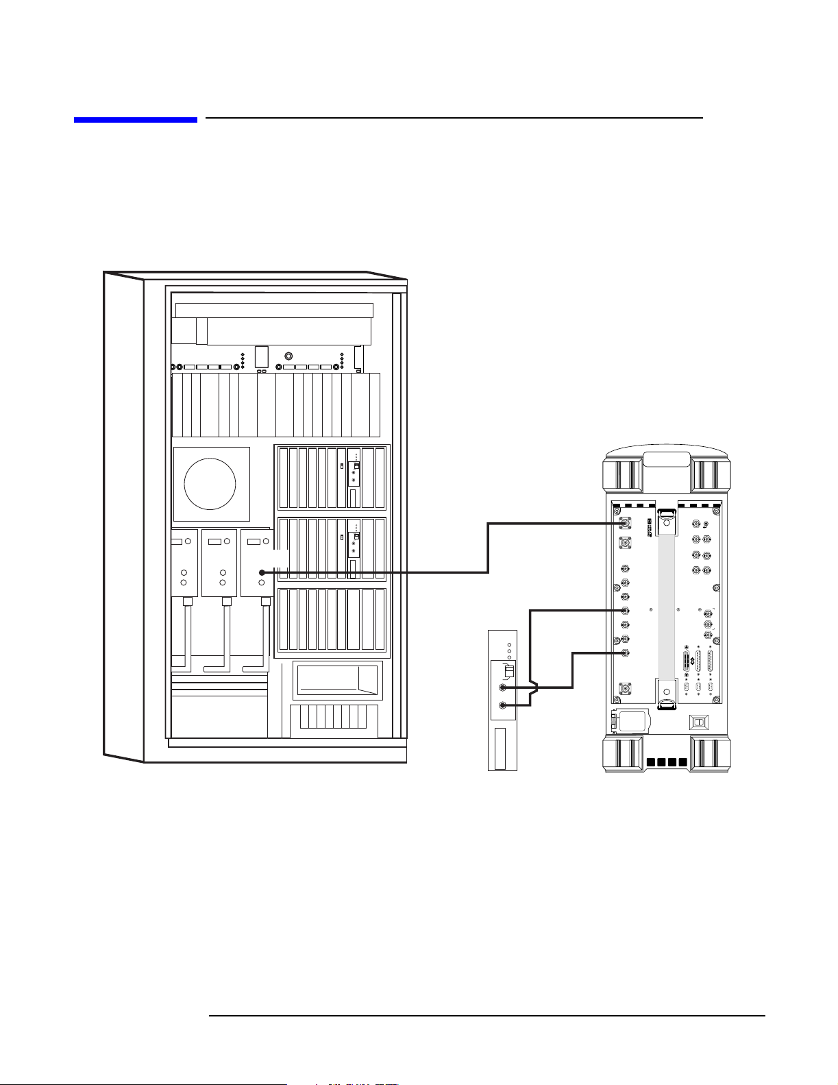
Figure 3-1 PCS Minicell Base Station TX Test Port (In Service) Connections
Side 0 Side 1
J2
TP REF OUT
J2
P' J3 J5
RFTG-m-RB RFTG-m-XO
NO GPS
FAULT
J4
STBY
J8
ON
6 MHz
J7
J2
J3 J55 J8*
P'
PREF IN
NO GPS
FAULT
J4
STBY
ON
6 MHz
LUCENT
ALM
NVM
ACT
AUTO
ON
TST
CLK
OFF
OFF
J2
CLK
J3
2PPS
LUCENT
ALM
NVM
ACT
AUTO
ON
TST
CLK
OFF
OFF
J2
CLK
J3
(SMA)
2PPS
inservc1.eps
1
The TST CLK switch on the SCT module must be set to ON.
J2 CLK
(SMA)
LUCENT
ALM
NVM
ACT
ON
TST
1
CLK
OFF
J2
CLK
J3
2PPS
ANT IN (N[f])
EVEN SECOND
SYNC IN (BNC)
EXT REF
IN (BNC)
J3 2PPS
(SMA)
MODULATION
8935 CDMA
ANALOG
IN
AUDIO OUT
MONITOR
SCOPE
OUT
EXT SCOPE
HI
TRIG IN
AUDIO IN
VIDEO
OUT
LO
BASEBAND OUT
QI
DATA
IN
PARALLEL PORT 15
PARALLEL PORT 16
SERIAL 10
SERIAL 11
SERIAL 9
ANT IN DUPLEX OUT
CHIP CLOCK
MHz OUT
19.6608
16X
CHIP CLOCK
MHz OUT
1.2288
FRAME
CLOCK
OUT
SECOND
SYNC IN
EVEN
QUALIFIER
TRIGGER
IN
REF OUT
10 MHz
REF IN
EXT
RF IN/OUT
46
Chapter 3
Page 46
Connections
Test Set to Base Station Connections
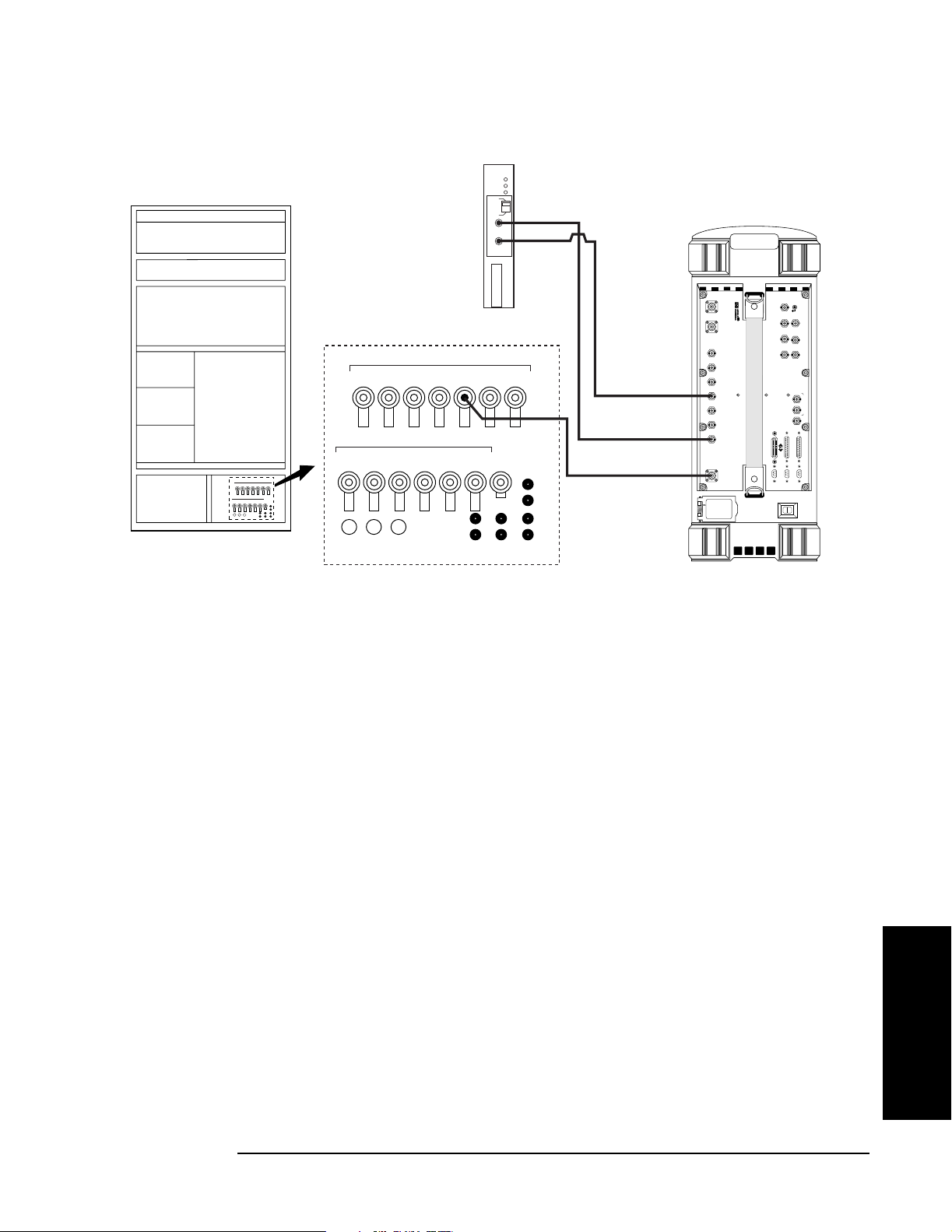
Figure 3-2 PCS Minicell Base Station TX Antenna Port (Out of Service) Connections
LUCENT
ALM
NVM
PCS Minicell Rearview
Tx
S3p S3g S2p S2g S1p S1g Sage
Rx/dx
S3d1/g
S2d1/g
S3d0/p
S2d0/p
S1d0/p
J2 CLK
(SMA)
AIP
Tx
S3p S3g S2p S2g S1p S1g Sage
Rx/dx
S3d1/g
S3d0/p
S1d1/g
G
ps
S2d0/p
S2d1/g
S1d0/p
1
S1d1/g
ACT
ON
TST
CLK
OFF
J2
CLK
J3
2PPS
Gps
J3 2PPS
(SMA[m])
EVEN SECOND
SYNC IN
(BNC[m])
REF IN (BNC[m])
EXT
RF IN/OUT (N[m])
MODULATION
8935 CDMA
ANALOG
IN
AUDIO OUT
MONITOR
SCOPE
OUT
EXT SCOPE
HI
TRIG IN
AUDIO IN
VIDEO
OUT
LO
BASEBAND OUT
QI
DATA
IN
PARALLEL PORT 15
PARALLEL PORT 16
SERIAL 10
SERIAL 11
SERIAL 9
ANT IN DUPLEX OUT
CHIP CLOCK
MHz OUT
19.6608
16X
CHIP CLOCK
MHz OUT
1.2288
FRAME
CLOCK
OUT
SECOND
SYNC IN
EVEN
QUALIFIER
TRIGGER
IN
REF OUT
10 MHz
REF IN
EXT
RF IN/OUT
outserv1.eps
1
The TST CLK switch on the SCT module must be set to ON.
Connections
Chapter 3
47
Page 47
Connections
Test Set to Base Station Connections
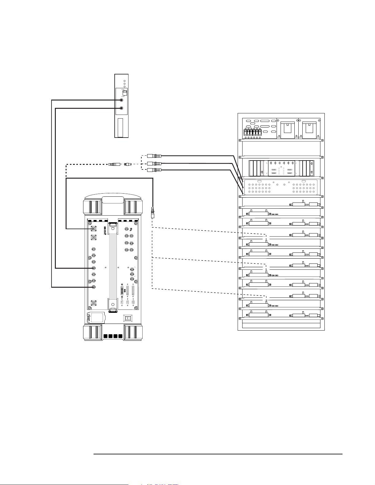
Figure 3-3 Series II Base Station Test Port (In Service) Connections
SCT Card
LUCENT
ALM
NVM
ACT
ON
TST
CLK
1
OFF
CLOCK
Alternate Cable
N-Type (M) to SMA (M)
N-Type (M) to SMA (M)
E6380 Test Set
2PPS
J2
CLK
J3
2PPS
SMA (F)
Barrel
Switch Panel
Alternate Connections
TX Test Port 1 Cable (J11)
TX Test Port 2 Cable (J12)
TX Test Port 3 Cable (J13)
Antenna Interface Frame
J10 J11 J12 J13P1J14 J15 J16 J3 J4
J30 J31 J32 J33 J34 J35 J36
J50 J51 J52 J53 J54 J55 J56
J1 J2 J3 J4 J5 J6
REF 0 REF 1
NO GPS
15 MHZ
ALM
STBY
ON
J1 J2
RTU SWITCH PANEL
J26 J25 J24 J23P2J22 J21 J20
J46 J45 J44 J43 J42 J41 J40
J66 J65 J64 J63 J62 J61 J60
MODULATION
ANT IN DUPLEX OUT
8935 CDMA
CHIP CLOCK
MHz OUT
19.6608
16X
CHIP CLOCK
MHz OUT
1.2288
FRAME
CLOCK
EVEN SECOND
SYNC IN
EXT REF IN
1
The TST CLK switch on the SCT module must be set to ON.
OUT
SECOND
SYNC IN
EVEN
QUALIFIER
TRIGGER
IN
REF OUT
10 MHz
REF IN
EXT
RF IN/OUT
ANALOG
IN
AUDIO OUT
MONITOR
SCOPE
OUT
EXT SCOPE
HI
TRIG IN
AUDIO IN
VIDEO
OUT
LO
BASEBAND OUT
QI
DATA
IN
PARALLEL PORT 15
PARALLEL PORT 16
SERIAL 10
SERIAL 11
SERIAL 9
If shelf space permits, connect
here otherwise connect to other
end of cable in the switch panel.
If shelf space permits, connect
here otherwise connect to other
end of cable in the switch panel.
If shelf space permits, connect
here otherwise connect to other
end of cable in the switch panel.
TX Test Port 3
TX Test Port 2
TX Test Port 1
48
inservice.eps
Chapter 3
Page 48

Test Set to Base Station Connections
Figure 3-4 Series II Base Station TX Antenna Port (Out of Service) Connections
Connections
EVEN SECOND
SYNC IN
EXT REF IN
RF IN/OUT
SCT Card
LUCENT
ALM
NVM
ACT
ON
TST
CLK
2PPS
OFF
J2
CLK
J3
2PPS
CLOCK
E6380 Test Set
MODULATION
ANALOG
IN
MONITOR
SCOPE
OUT
EXT SCOPE
TRIG IN
VIDEO
OUT
QI
IN
PARALLEL PORT 16
SERIAL 10
SERIAL 11
MHz OUT
MHz OUT
OUT
SYNC IN
IN
REF OUT
REF IN
ANT IN DUPLEX OUT
CHIP CLOCK
19.6608
CHIP CLOCK
1.2288
FRAME
CLOCK
SECOND
EVEN
QUALIFIER
TRIGGER
10 MHz
EXT
RF IN/OUT
8935 CDMA
16X
1
AUDIO OUT
HI
AUDIO IN
LO
BASEBAND OUT
DATA
PARALLEL PORT 15
SERIAL 9
TX Antenna
Port 3
TX Antenna
Port 2
TX Antenna
Port 1
Antenna Interface Frame
J1 J2 J3 J4 J5 J6
REF 0 REF 1
NO GPS
15 MHZ
ALM
STBY
ON
J10 J11 J12 J13P1J14 J15 J16 J3 J4
J30 J31 J32 J33 J34 J35 J36
J50 J51 J52 J53 J54 J55 J56
J1 J2
RTU SWITCH PANEL
J26 J25 J24 J23P2J22 J21 J20
J46 J45 J44 J43 J42 J41 J40
J66 J65 J64 J63 J62 J61 J60
1
The TST CLK switch on the SCT module must be set to ON.
Chapter 3
N-Type Female
Barrel Connector
outservice.eps
Connections
49
Page 49

Connections
Test Set to GPS Time and Frequency Reference Receiver Connections
Test Set to GPS Time and Frequency Reference
Receiver Connections
Figure 3-5 shows the connections to the Test Set when using a Symmetricom 58503A
GPS Time and Frequency Reference Receiver to establish a time base. This
configuration uses a GPS signal for the Test Set timebase instead of connecting to the
cell site SCT modules. See “GPS Time and Frequency Reference Receiver” on page 17 for
information on electing to use the 58503A.
When using the 58503A, make certain to set the REF IN Connected to field on the Test
Configuration Menu to GPS Receive r (see “Test Configuration” on page 39).
Figure 3-5 Symmetricom 58503A GPS Time and Frequency Reference Receiver
Connections
ESEC
ESEC
OUTPUTS
PORT 1
SYNC IN
EVEN SECOND
REF IN
Alarm
(TTL)
I/O
SERIAL PLATE
10 MHz
OUT
10 MHz OUT
ANTENNA
ANT IN DUPLEX
MHz OUT
19.6608
MHz OUT
1.2288
FRAME
CLOCK
SECOND
EVEN
TRIG/QUAL
IN
REF OUT
10 MHz
REF IN
RF IN/OUT
CHIP CLOCK
16X
CHIP CLOCK
SYNC IN
OUTPUT
MODULATION
INPUT
MONITOR
AUDIO
EXT SCOPE
TRIG IN
VIDEO
OUT
SERIA PORT
AUDIO OUT
HI LO
AUDIO IN
BASEBAND OUT
QI
IN
PARALLEL PORT
PARALLEL PORT
SERIA PORT
SERIA PORT
50
Chapter 3
Page 50

Performing Tests
4 Performing Tests
This chapter describes detailed procedures to be used in running the Test Software tests
and utilities.
Chapter 4
51
Page 51

Performing Tests
Overview
Overview
NOTE Testing might be interrupted if cell site diagnostics are initiated by the MSC while tests
are being run. To prevent this, use a personal computer (PC) (usually a laptop PC) to
send a command to inhibit diagnostics from the MSC before testing.
These test procedures describe the process from setting up a test to obtaining test
results. To simplify the procedures, all are written to use a PC to communicate with the
MSC (where applicable) and the Test Software will be set to send control commands.
Before making measurements, verify that you have performed the following setup and
configuration processes:
• “Loading and Running the Test Software” on page 23.
• “Operating the BTS Laptop Utility Program” on page 27.
• “Connecting the PC to the Test Set and the MSC” on page 32.
• “Configuring the Test Software” on page 38.
• “Establishing a Connection with the MSC for Testing” on page 43.
52
Chapter 4
O:\Manuals\E6385A_Cd ma\Book\perf-tst.fm
Page 52

Performing Tests
Overview
Calibrating the Test Setup
If you did not know the Base Station TX Antenna Port Cable Loss, or the Base Station
TX Test Port Cable Loss, or the Base Station TX Coupler Losses when you entered the
data on the Base Station Configuration Menu screen, run the following calibration
routines to determine these losses. Determining these losses is crucial to obtaining
accurate test results.
Access these routines by loading and running the Test Software (see “Loading and
Running the Test Software” on page 23) and selecting Calibration/Utiliti es from
the Lucent CDMA Tests Main Menu screen. The Test Software will display the
Calibration/Utilities Menu screen (see Figure 4-1). After each measurement, the
program will enter the value automatically into the Test Software for future testing
(without your having to rerun the routines every time that you test). However, if you run
a different program after the measurements, you must re-measure (or re-enter) the
values the next time that you use the Test Software.
The Calibration procedures are:
• “TX Antenna Port Cable Calibration Test” on page 75. Run this utility to determine
antenna port cable losses at the frequency and power level at which testing will be
performed.
Performing Tests
• “TX Test Port Cable Calibration Test” on page 76. Run this utility to determine test
port cable losses at the frequency and power level at which testing will be performed.
• “TX Test Port Calibration Test” on page 77. Run this utility to determine the exact
coupling factor (loss) of the Base Station TX Test Port.
Figure 4-1 Calibration/Utilities Menu Screen
Chapter 4
53
Page 53
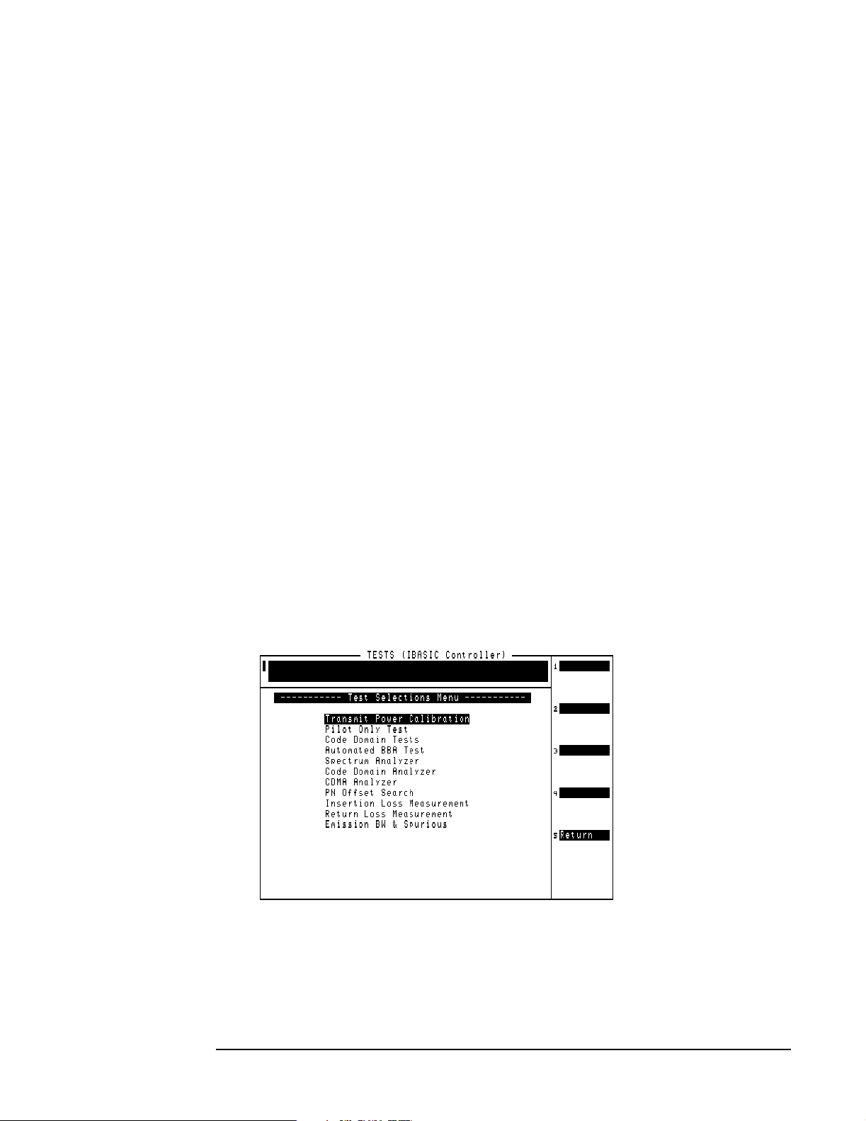
Performing Tests
Overview
Selecting Tests
Select tests by loading and running the Test Software (see “Loading and Running the
Test Software” on page 23) and selecting the Test Selections field on the Lucent
CDMA Tests Main Menu screen. The Test Software will display the Test Selections
Menu screen (see Figure 4-2). Note that the several calibration and utility procedures
(PN Offset Search, Insertion Loss Test, and Return Loss Test) are also available on this
screen.
Once you have selected a test to run, see the following list to locate the description of
that test.
• “Transmit Power Calibration Test (Autoplex Series II)” on page 56.
• “Transmit Power Calibration Test (PCS Minicell)” on page 58
• “Pilot Only Test” on page 62.
• “Code Domain Tests” on page 64.
• “Automated BBA Test” on page 66.
• “Spectrum Analyzer Test” on page 68.
• “Code Domain Analyzer Test” on page 70.
• “CDMA Analyzer Test” on page 73.
• “PN Offset Search Test” on page 79.
• “Insertion Loss Measurement” on page 80.
• “Return Loss Measurement” on page 82.
• “Emission BW & Spurious Test” on page 84.
Figure 4-2 Test Selections Screen
54
Chapter 4
O:\Manuals\E6385A_Cd ma\Book\perf-tst.fm
Page 54

Performing Tests
Overview
Running Tests
NOTE Before starting to run operational tests, make certain that you have set PARAMETER
23. ZZZZ Test Demo Mode [0=normal 1=demo] to 0.
You are now ready to select and run tests. On the Test Selections Menu screen, scroll to
the test that you wish to run, and press the knob to select it. The test will run. You may
then select another test and run it in the same manner. You may repeat this operation as
many times as is necessary.
After successfully running the tests, it is recommended that you save all of the
configuration information as a procedure file on an SRAM card for later retrieval (see
“Saving/Deleting a Procedure” on page 101). This eliminates the requirement for
re-entering the information if you run a different program, change parameters when
testing another Base Station, or install new operating system firmware in the Test Set.
For More Information
For more details on the tests in this chapter:
Performing Tests
• “Parameters” on page 110
• “Specifications (Pass/Fail Limits)” on page 115
If there were problems or error messages were displayed when running a test:
See Chapter 6, “Troubleshooting,” on page 119.
Chapter 4
55
Page 55

Performing Tests
Transmit Power Calibration Test (Autoplex Series II)
Transmit Power Calibration Test (Autoplex Series II)
This test provides an analog display of power measurements. This mode is useful when
making adjustments to power levels on a transmitter.
This test may be performed in-service using the Base Station TX Test Port, or
out-of-service using the Base Station TX Antenna Port (see “Which Base Station Port to
Use – TX Test or TX Antenna?” on page 36).
Features of the power meter display include:
• Tick marks on the meter to indicate when a power level setting is within the desired
limits.
• Audible tones to indicate whether the power reading falls within specified limits.
Make certain to use the correct Test Set input port for the power level to be measured
(see “Which Test Set Port to Use – ANT IN or RF IN/OUT?” on page 36).
For Automated Base Station Control:
If you have configured the Test Software to control the Base Station automatically,
the Test Software will send a command to the MSC to set the BCR attenuation to the
level specified on the Base Station Configuration Menu screen.
However, the Test Software cannot override a minimum BCR attenuation level that
has been set in the translation tables of the MSC CEQFACE form. If the measured
power is not within specifications, make certain that the BCR Attenuati on setting on
the Base Station Configuration Menu screen is not set to a lower value than the
minimum BCR attenuation level listed in the translation tables.
For Manual Base Station Control:
If you have configured the Test Software to require manual control of the Base
Station, make certain that the BCR Attenuation setting on the Base Station
Configuration Menu screen matches the BCR attenuation setting on the MSC
CEQFACE control form. If these values are different, the TX Power Meter
measurement might be incorrect.
NOTE Transmitter power is partly controlled by the MSC using the BCR attenuation setting.
The value for this setting, and the corresponding TX power of the Base Station, varies
between models of Base Station and individual Base Station location.
It is very important that you set correctly the BCR Atten uation Level and Speci fied
Output Power on the Base Station Configuration Menu screen (see “Base Station
Configuration” on page 41).
Parameters and Specifications Used
The following specifications and parameters are used when running this test. See
Chapter 5, “Reference,” for descriptions of the specifications and parameters.
Par ameters:
• None used for this test.
56
Chapter 4
O:\Manuals\E6385A_Cd ma\Book\perf-tst.fm
Page 56

Performing Tests
Transmit Power Calibration Test (Autoplex Series II)
Specifications (Pass/Fail Limits):
• 6. Output Power Adjustment Error. This specification determines where the low and
high tick marks appear on the measurement graphic scale.
Select and Run the Test
Perform the Transmit Power Calibration Test as follows:
Step 1. From the Lucent CDMA Tests Main Menu screen, select the Test Selections field. The
Test Software will display the Test Selections Menu screen.
Step 2. Select the Transmit Power Calibration field.
Step 3. Follow the displayed instructions and diagram to make the measurement.
NOTE This procedure might include steps that prompt you to disconnect cables from the site
antenna ports and make connections to the Test Set. Before removing or re-installing the
antenna cables, make certain that the transmitter has been turned off by the MSC (or by
switch personnel if not using a PC). The green ACT LEDs on the ACU and BCR modules
indicate the transmitter is active, and therefore should be off before disconnecting
cables.
Performing Tests
Review the Results
The Test Software will display the power meter screen (see Figure 4-3).
The power meter will display defaults to units of Watts. To view the power level in dBm,
press the
adjusting the transmitter power without looking at the display. Adjust the tone volume
by pressing the
Figure 4-3 Power Meter Display
The longer tick marks
are the high and low
specification limits.
This prompt indicat es if
power is low, within
specifications, or high.
These values indicate
the meter high and low
display limits.
k3 (dBm) key. A beeping tone will accompany the measurement to assist in
k4 (Tns off, Tns quiet, Tns loud) key.
Chapter 4
57
Page 57

Performing Tests
Transmit Power Calibration Test (PCS Minicell)
Transmit Power Calibration Test (PCS Minicell)
This test measures and calibrates the PCS Minicell RF transmit power. This test must
be performed with the Base Station out-of-service using the Base Station TX Antenna
Port. This test applies to both the 8-watt CDMA transmitter unit (CTU) and the 16-watt
high-power CDMA transmitter unit (HPCTU). Also, it allows for settings for custom
configurations.
The basic procedure for testing at the Base Station Antenna Output Port is as follows:
• Determine and input to the Test Software which routine diagnostics are to be
inhibited on the Base Station during the test, and whether functional testing and call
processing are also to be inhibited on the Base Station. The Test Software will send
the appropriate CFR commands to the Base Station.
• If not already done, calibrate the Test Cables that will be used in measuring the Base
Station output power.
• Determine and input to the Test Software the type of power amplifier used in the
Base Station (CTU, HPCTU1, HPCTU2, HPCTU3, or HPCTU4). If you do not know
the amplifier type, contact your engineering department.
• Determine the BCR attenuation factor from the forms in an APX/RCV session. After
obtaining this information, input it to the Test Software. (You may use the BTS
Laptop Utility program SWITCH TERMINAL window to set the forms.
• Once the Amplifier Type and BCR Attenuation Factor have been identified to the
Test Software, it will determine the number of Channel Elements to add to the
carrier to perform the power calibration test.
• Based on the Amplifier Type and BCR Attenuation Factor, the Test Software will
determine the Calibration Power Level to be expected from the Base Station. This is
the power level to which the amplifier will be adjusted during the test.
• The Amplifier Type selected will require that certain translations be set in the forms
in an APX/RCV session. The Test Software will supply the translation values and
identify the forms on which to set those values. You may use the BTS Laptop Utility
program SWITCH TERMINAL window to set the forms.
NOTE IMPORTANT: If you change the translation values for this test, you must restore the
values at the end of the test.
• The Test Software will send commands to the Base Station to configure the BBA
under test and turn off the transmitter.
• Once the BBA stops transmitting, connect the test cables between the Test Set and
the Base Station Power Output to measure the power.
• The Test Software will issue commands to cause the BBA to start transmitting.
• The Test Software will display a power meter to allow you to adjust the Base Station
power to the proper range.
• The Test Software will display the Base Station power in watts and dBm on the Test
Set screen and in the BTS Laptop Utility program Test Results window.
• The Test Software will again turn off the transmitter.
58
O:\Manuals\E6385A_Cd ma\Book\perf-tst.fm
Chapter 4
Page 58

Performing Tests
Transmit Power Calibration Test (PCS Minicell)
• Once the transmitter is turned off, remove the test cables and re-connect the Base
Station power output to the antenna system.
• The Test Software will send commands to the Base Station to restore the BBA.
• The Test Software will then allow you to select whether to re-allow the routine
diagnostics, functional test, and call processing that you inhibited at the beginning of
the test. Based on your choices, the Test Software will send appropriate commands
the Base Station.
NOTE If multiple faces are to be tested, repeat the above process for each face to be tested, then
verify cell site operation and perform pilot level functional test calibration for any
BBAs that were re-calibrated.
Parameters and Specifications Used
The following specifications and parameters are used when running this test. See
Chapter 5, “Reference,” for descriptions of the specifications and parameters.
Par ameters:
Performing Tests
• None used for this test.
Specifications (Pass/Fail Limits):
• 6. Output Power Adjustment Error. This specification determines where the low and
high tick marks appear on the measurement graphic scale.
Test Set-Up Procedure
Set up the Test Software and Base Station for running the Transmit Power Calibration
Test as follows:
Step 1. From the Lucent CDMA Tests Main Menu screen, select the Test Selections field. The
Test Software will display the Test Selections Menu screen.
NOTE The Transmit Power Calibration Test includes steps that prompt you to disconnect
cables from the site antenna ports and make connections to the Test Set. Before
removing or re-installing the antenna cables, make certain that the transmitter has
been turned off by the MSC (or by switch personnel if not using a PC). The green ACT
LEDs on the ACU and BCR modules indicate the transmitter is active, and therefore
should be off before disconnecting cables.
Step 2. Select the Transmit Power Calibratio n field. The Test Software will display a prompt
directing that you remove RF connections and such.
Chapter 4
Step 3. Follow the displayed instructions, then press the
will display an information screen stating that it is performing calibration, then it will
display the Transmit Power Calibration screen.
k1 (Proceed) key. The Test Software
59
Page 59

Performing Tests
Transmit Power Calibration Test (PCS Minicell)
Step 4. On the Transmit Power Calibration screen, scroll to and set the fields as follows:
Cell Site Numbe r – Rotate the knob or use the DATA ENTRY keys to enter the
number, then either press the knob or the
Enter key to select that number.
Measurement Por t – Press the knob to toggle the field to TX Antenna P ort .
BBA Number – Rotate the knob or use the DATA ENTRY keys to enter the number of the
BBA, then either press the knob or the
Enter key to select that number.
Channel Number – Rotate the knob or use the DATA ENTRY keys to enter the channel
number, then either press the knob or the
Enter key to select that number.
PN Offset – Rotate the knob or use the DATA ENTRY keys to enter the value, then
either press the knob or the
Enter key to select that value.
Send Control Co mmands to MSC – Press the knob to toggle the field to Yes to have the
Test Software send the control commands.
NOTE Although it is usually possible to control the Base Station by manual methods, this test
procedure description uses a PC.
Do you need ass istance? – Press the knob to toggle the field to the desired setting. If
you understand the testing setup and wish to just enter the required information for the
Test Software to perform the test, select No. If you wish to have the Test Software display
informational screens at appropriate points in the testing process to assist you in setting
up the Base Station for testing, select Yes.
TX Antenna Port Cable Loss – If you know the loss through the cable, rotate the knob
or use the DATA ENTRY keys to enter the value, then either press the knob or the
key to select that value. If you are uncertain of the value, run the “TX Antenna Port
Cable Calibration Test” on page 75 to have the Test Software determine the value and
enter it in this field automatically.
Step 5. Press the
k1 (Run) key. The Test Software will run the test.
Select and Run the Test
Perform the test procedure as follows:
Step 1. Assuming that you pressed the
Software will display the Before Beginning the Power Calibration screen. Follow the
on-screen instructions to inhibit routine diagnostics and call processing. Set all fields to
Yes, then press the
inhibit the diagnostics and call processing
If you select Yes in the Do you need assi stance ? field, the Test Software will display
on-screen instructions to direct you through a step-by-step process to determine the
Power Amplifier Type, BCR Attenuation, Number of Channel Elements, and Calibration
Power, and to make connections as required. It will also instruct you as to as to how to
verify the information in the APX/RCV forms. This information will all be displayed in
summary form on the Transmit Power Calibration Menu screen.
k1 (Snd Cmds) key. The Test Software will send the commands to
Enter
k1 (Run) key in the Test Set-Up procedure, the Test
If you select No in the Do you need assis tance? field, the Test Software will display
the Transmit Power Calibration Menu screen.
60
O:\Manuals\E6385A_Cd ma\Book\perf-tst.fm
Chapter 4
Page 60

Performing Tests
Transmit Power Calibration Test (PCS Minicell)
Step 2. On the Transmit Power Calibration Menu screen, scroll to and set the fields as follows:
Power Amplifier Type – Press the knob and select the PA type from the drop-down
Choices: list. The available choices are: CTU, HPCTU 1, HPCTU 2, HPCTU 3, HPCTU 4, and
CUSTOM.
BCR Attenuation – Rotate the knob or use the DATA ENTRY keys to enter the
attenuation value, then either press the knob or the
Enter key to select that number.
NOTE The functions of the following two fields are dependent upon the setting of the Power
Amplifier Type field. The following two fields are operable only if the Power
Amplifier Type field is set to CUSTOM.
Number of Channel Elemen ts – If the power amplifier to be tested requires custom
settings, rotate the knob or use the DATA ENTRY keys to enter the number, then either
press the knob or the
Enter key to select the desired number of channel elements for the
test.
If the power amplifier to be tested does not require custom settings, this field will
indicate the number of channel elements that will be added to the carrier for the test.
Calibration Pow er – If the power amplifier to be tested requires custom settings,
rotate the knob or use the DATA ENTRY keys to enter the number, then either press the
knob or the
Enter key to set the power level out of the Base Station for the test.
Performing Tests
If the power amplifier to be tested does not require custom settings, this field will
indicate the expected power level out of the Base Station.
NOTE For the following five fields, verify (and change if necessary) the setting using the
APX/RCV forms. Use the BTS Laptop Utility program on the PC to obtain these forms
from the ECP.
IMPORTANT: If you change these values, remember to restore the settings at the end
of the test.
Traffic Channel Gain - M ax for R ate Se t 1 – Verify the setting.
Max Power (Watts) – Verify the setting.
Pilot Channel G ain (dgu) – Verify the setting.
Paging Channel Gain (dgu ) – Verify the setting.
Synch Channel G ain (dgu) – Verify the setting.
Step 3. Press the
k1 (Run) key and follow the on-screen instructions.
Chapter 4
61
Page 61

Performing Tests
Pilot Only Test
Pilot Only Test
This test performs a suite of CDMA tests on a carrier with only the pilot channel active
(no active traffic or paging channels). Therefore, this test may be performed only with
the Base Station out-of-service.
The tests performed are:
• Rho (modulation quality)
• Pilot Time offset
• Frequency error
• Carrier feedthrough
Parameters and Specifications Used
The following specifications and parameters are used when running this test. See
Chapter 5, “Reference,” for descriptions of the specifications and parameters.
Par ameters:
•None
Specifications (Pass/Fail Limits):
• 1. Carrier Feedthrough
• 5. Frequency Error
• 8. Rho
• 9. Time Offset
Select and Run the Test
Perform the Pilot Only Test as follows:
Step 1. From the Lucent CDMA Tests Main Menu screen, select the Test Selections field. The
Test Software will display the Test Selections Menu screen.
Step 2. Select the Pilot Only Test field.
Step 1. Follow the displayed instructions and diagram to make the measurement.
NOTE This procedure might include steps that prompt you to disconnect cables from the site
antenna ports and make connections to the Test Set. Before removing or re-installing the
antenna cables, make certain that the transmitter has been turned off by the MSC (or by
switch personnel if not using a modem). The green ACT LEDs on the ACU and BCR
modules indicate the transmitter is active, and therefore should be off before
disconnecting cables.
62
Chapter 4
O:\Manuals\E6385A_Cd ma\Book\perf-tst.fm
Page 62
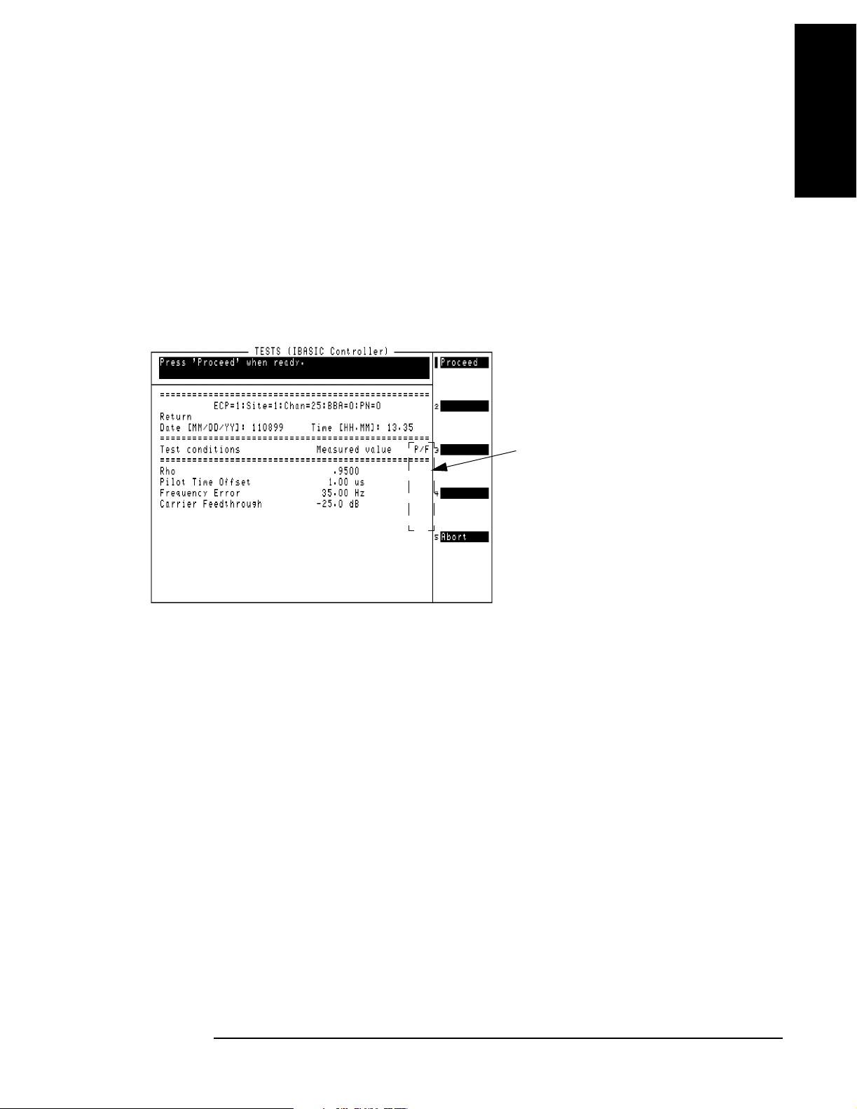
Review the Results
The Test Software will begin running pilot channel tests on the selected BBA. During the
test, results will be displayed with a failure indication if a measurement falls outside the
specified limits (see Figure 4-4).
To see the pass/fail limits for each data point as it is measured, use the BTS Laptop
Utility program Test Results window.
When the testing is complete, the Test Software will pause to allow you to review the
on-screen test results. Press the
screen.
Figure 4-4 Results from the Pilot Only Test Sequence
k1 (Proceed) key to return to the Test Selections Menu
Performing Tests
The “F” (Fail) indicates that the
measured value is o uts id e o f th e
specified limits. To change limits,
see “Changing Pass/Fail Limits”
on page 98.
Performing Tests
Pilot Only Test
Chapter 4
63
Page 63

Performing Tests
Code Domain Tests
Code Domain Tests
This test performs a suite of CDMA transmitter tests on the selected BBA. Unlike the
Pilot Only test, in this test one or more traffic channels (channel elements) are turned
on.
When you are sending commands to the MSC, you must enter the number of channel
elements (CEs) to test on the Base Station Configuration Menu screen. Call processing
must be deactivated by sending the Inhibit cp command in the BTS Laptop Utility
program Switch Terminal window or by some other means, before testing begins. For
information on enabling automated control, see “Base Station Configuration” on page
41.
The following measurements are performed:
• Time offset
• Frequency error
• Carrier feedthrough
• Code domain tests on traffic channels (if CEs are configured)
TX Walsh code power
Estimated rho
Walsh co d e tim i n g
Walsh co d e pha s e
Parameters and Specifications Used
The following specifications and parameters are used when running this test. See
Chapter 5, “Reference,” for descriptions of the specifications and parameters.
Par ameters:
• 5. GN Code Domain Power Threshold
• 6. GN Print Inactive Walsh Codes [0=no 1=yes]
Specifications (Pass/Fail Limits):
• 1. Carrier Feedthrough
• 2. Code Domain Floor
• 3. Code Domain Phase
• 4. Code Domain Timing
• 5. Frequency Error
• 9. Time Offset
64
Chapter 4
O:\Manuals\E6385A_Cd ma\Book\perf-tst.fm
Page 64

Performing Tests
Code Domain Tests
Select and Run the Test
Perform the Code Domain Tests as follows:
Step 1. From the Lucent CDMA Tests Main Menu screen, select the Test Selections field. The
Test Software will display the Test Selections Menu screen.
Step 2. Select the Code Domain Tests field.
Step 3. Follow the displayed instructions and diagram to make the measurement.
NOTE This procedure might include steps that prompt you to disconnect cables from the site
antenna ports and make connections to the Test Set. Before removing or re-installing the
antenna cables, make certain that the transmitter has been turned off by the MSC (or by
switch personnel if not using a modem). The green ACT LEDs on the ACU and BCR
modules indicate the transmitter is active, and therefore should be off before
disconnecting cables.
Review the Results
The Test Software will begin running code domain tests on the selected BBA. After tests
are performed, test results will begin showing on the display. See Figure 4-5. Failures
will be indicated in the P/F column if a measurement falls outside the specified limits.
Performing Tests
If you wish to stop testing before the sequence is complete, press the
Depending on the state of the system, it might take as long as 60 seconds for the test to
stop.
Figure 4-5 Final Results from the Code Domain Tests
k5 (Abort) key.
Chapter 4
65
Page 65

Performing Tests
Automated BBA Test
Automated BBA Test
This test performs a suite of CDMA transmitter tests on the selected BBA. This test
requires that the Test Software send control commands to the MSC.
The test sequence includes the following tests:
• Pilot Channel Tests
Rho
Time Offset
Frequency Error
Carrier Feedthrough
• Code Domain Tests on traffic channels (if CEs are configured)
TX Walsh Code Power
Walsh Code Timing
Walsh C o d e Pha s e
Estimated Rho
• Code Domain Tests on pilot and paging channels (active mode)
Parameters and Specifications Used
The following specifications and parameters are used when running this test. See
Chapter 5, “Reference,” for descriptions of the specifications and parameters.
Par ameters:
• 5. GN Code Domain Power Threshold
• 6. GN Print Inactive Walsh Codes [0=no 1=yes]
Specifications (Pass/Fail Limits):
• 1. Carrier Feedthrough
• 2. Code Domain Floor
• 3. Code Domain Phase
• 4. Code Domain Timing
• 5. Frequency Error
• 8. Rho
• 9. Time Offset
66
Chapter 4
O:\Manuals\E6385A_Cd ma\Book\perf-tst.fm
Page 66

Performing Tests
Automated BBA Test
Select and Run the Test
Perform the Automated BBA Test as follows:
Step 1. From the Lucent CDMA Tests Main Menu screen, select the Test Selections field. The
Test Software will display the Test Selections Menu screen.
Step 2. Select the Automated BBA Test field.
Step 3. Follow the displayed instructions and diagram as prompted to make the measurement.
NOTE This procedure might include steps that prompt you to disconnect cables from the site
antenna ports and make connections to the Test Set. Before removing or re-installing the
antenna cables, make certain that the transmitter has been turned off by the MSC (or by
switch personnel if not using a modem). The green ACT LEDs on the ACU and BCR
modules should be off.
Review the Results
The Test Software will begin running tests on the active BBA. See Figure 4-6. As tests
are performed, test results will begin showing on the display with a failure indication if a
measurement falls outside the specified limits.
Performing Tests
If you wish to stop testing before the sequence is complete, press the
Depending on the state of the system, it might take as long as 60 seconds to stop the test.
Because the site configuration might not have been reset before testing was aborted, the
Test Software will offer a choice to send a “multistop” command to reset the BBAs.
Figure 4-6 Partial Code Domain Tests Sequence Results
k5 (Abort) key.
Chapter 4
67
Page 67

Performing Tests
Spectrum Analyzer Test
Spectrum Analyzer Test
This test configures the Test Software to display spectrum sweeps. This mode is useful
when you would like to verify the presence of a CDMA signal or search for sources of
interference.
Parameters and Specifications Used
The following specifications and parameters are used when running this test. See
Chapter 5, “Reference,” for descriptions of the specifications and parameters.
Par ameters:
• None used for this test.
Specifications (Pass/Fail Limits):
• None used for this test.
Select and Run the Test
Perform spectrum analyzer measurements as follows:
Step 1. From the Lucent CDMA Tests Main Menu screen, select the Test Selections field. The
Test Software will display the Test Selections Menu screen.
Step 2. Select the Spectrum Analyzer field.
Step 3. Follow the displayed instructions and diagram to make the measurement.
NOTE This procedure might include steps that prompt you to disconnect cables from the site
antenna ports and make connections to the Test Set. Before removing or re-installing the
antenna cables, make certain that the transmitter has been turned off by the MSC (or by
switch personnel if not using a modem). The green ACT LEDs on the ACU and BCR
modules indicate the transmitter is active, and therefore should be off before
disconnecting cables.
Review the Results
The Test Software sets up and displays the spectrum analyzer. See Figure 4-7.
68
Chapter 4
O:\Manuals\E6385A_Cd ma\Book\perf-tst.fm
Page 68

Figure 4-7 Spectrum Analyzer Display
Use the Ref Level and Span fields for the best view of the transmitted signal.
Read the marker frequency and level in the upper-right of the display. If you would like
to change the marker position, select the Controls field, select Marker, then use the
Position field.
Performing Tests
Spectrum Analyzer Test
Performing Tests
NOTE Do not make changes to the Center Freq field.
If you would like to view another channel/frequency, return to the Lucent CDMA Tests
Main Menu screen and select the Base Station Configur ation field (to access the
Base Station Configuration Menu screen) and change the Channel Numbe r, then re-run
the test.
When you have finished using the spectrum analyzer, press the
follow the instructions on the display. The Test Software will return to the Test
Selections Menu screen.
Pause/Continue key and
Chapter 4
69
Page 69

Performing Tests
Code Domain Analyzer Test
Code Domain Analyzer Test
This test sets up the Test Software to make manual measurements on a CDMA
transmitter. This test is useful if you wish to switch between Code Domain Power, Code
Domain Timing, and Code Domain Phase measurement screens. It is also useful for
examining changes in Code Domain readings over time. Otherwise, it would probably be
better to use the automated tests: “Code Domain Tests” on page 64 and “Automated
BBA Test” on page 66.
Available measurements in the Code Domain Analyzer screen are:
• Code Domain Power
• Code Domain Timing
•Code Domain Phase
Parameters and Specifications Used
The following specifications and parameters are used when running this test. See
Chapter 5, “Reference,” for descriptions of the specifications and parameters.
Par ameters:
• None used for this test.
Specifications (Pass/Fail Limits):
• None used for this test.
Select and Run the Test
Perform code domain analyzer measurements as follows:
Step 1. From the Lucent CDMA Tests Main Menu screen, select the Test Selections field. The
Test Software will display the Test Selections Menu screen.
Step 2. Select the Code Domain Analyzer field.
Step 3. Follow the displayed instructions and diagram to make the measurement.
NOTE This procedure might include steps that prompt you to disconnect cables from the site
antenna ports and make connections to the Test Set. Before removing or re-installing the
antenna cables, make certain that the transmitter has been turned off by the MSC (or by
switch personnel if not using a modem). The green ACT LEDs on the ACU and BCR
modules indicate the transmitter is active, and therefore should be off before
disconnecting cables.
70
Chapter 4
O:\Manuals\E6385A_Cd ma\Book\perf-tst.fm
Page 70

Review the Results
The Test Software displays the Code Domain Analyzer (see Figure 4-8). You may then
make changes to the setup fields and view the code domain response for the transmitter
signal. Use the Meas urement field to choose between measurements of power, phase, and
timing.
Figure 4-8 Making Code Domain Analyzer Measurements
Code Domain Analyzer Test
The PN Offset, time offset,
frequency error, average
carrier feedthrough, and
estimated Rho for the CDMA
carrier are displayed h ere.
Performing Tests
Performing Tests
Select the Measurement field to change the
measurement type to Fast Pwr, Phase, or Timing. For
fast power measurements, you must access FP Setup in
the Controls menu and manually set the Time Offset.
NOTE Do not make changes to the Tune Freq field. It has been preset by the Test Software.
Changes to other fields might also cause measurements to fail.
Changing the Controls field from Ma in to Marker allows you to move the marker to any
Walsh Chan (0-63), with the resulting Lvl (level), Time, or Phse (phase) indicated for the
current marker position (depending on the Measuremen t field setting shown in Figure
4-8). See Figure 4-9.
Chapter 4
71
Page 71

Performing Tests
Code Domain Analyzer Test
Figure 4-9 Reading Individual Walsh Channel Measurements
To read the power Lvl, Time
error, or Phase error of an
individual W als h Channel:
1) Set the Controls to Marker.
2) Set the Wals h Chan to the
channel to be tested.
3) Read the value(s).
*
The Time and Phase measurements are only displayed if the
Measurement field is set to Phase or Timing. (See Figure 4-8).
*
When you have finished using the code domain analyzer screen, press the
Pause/Continue
key, and follow the directions on the screen. The Test Software will return to the Test
Selections Menu screen.
72
Chapter 4
O:\Manuals\E6385A_Cd ma\Book\perf-tst.fm
Page 72

Performing Tests
CDMA Analyzer Test
CDMA Analyzer Test
This test sets up the Test Software to make several measurements manually.
The following measurements may be performed:
• Channel Power
• Rho (modulation quality). The following measurements are also displayed when Rho
is selected:
— Time offset
— Frequency error
— Carrier feedthrough
• EVM
— The following measurements are also displayed when EVM is selected:
— Phase error
Performing Tests
— Magnitude error
• Average Power
NOTE The Rho and EVM measurements should be made with all traffic, paging, and sync
channels off; only the pilot channel should be transmitting.
Parameters and Specifications Used
The following specifications and parameters are used when running this test. See
Chapter 5, “Reference,” for descriptions of the specifications and parameters.
Par ameters:
• 19. TX Antenna Port Cable Loss
• 21. TX Test Port Cable Loss
Specifications (Pass/Fail Limits):
• None used for this test.
Select and Run the Test
Perform CDMA Analyzer operations as follows:
Chapter 4
Step 1. From the Lucent CDMA Tests Main Menu screen, select the Test Selections field. The
Test Software will display the Test Selections Menu screen.
Step 2. Select the CDMA Analyzer field.
73
Page 73

Performing Tests
CDMA Analyzer Test
Step 3. Follow the displayed instructions and diagram to select and make the measurement.
NOTE This procedure might include steps that prompt you to disconnect cables from the site
antenna ports and make connections to the Test Set. Before removing or re-installing the
antenna cables, make certain that the transmitter has been turned off by the MSC (or by
switch personnel if not using a modem). The green ACT LEDs on the ACU and BCR
modules indicate the transmitter is active, and therefore should be off before
disconnecting cables.
Step 4. Select the desired measurement from the displayed list. The Test Software will configure
itself and make the measurement. It might take several seconds before the
measurement results are displayed.
Review the Results
Channel power and average power are displayed as individual measurements.
Additional measurements are displayed if Rho or EVM is selected.
When you have finished using the CDMA analyzer, press the
k5 (Return) key to return to the CDMA Analyzer Choices menu screen.
Press the
k5 (Return) key again and follow the displayed instructions to return to the
Test Selections Menu screen.
74
Chapter 4
O:\Manuals\E6385A_Cd ma\Book\perf-tst.fm
Page 74

Performing Tests
TX Antenna Port Cable Calibration Test
TX Antenna Port Cable Calibration Test
This utility measures the signal loss through the cable used to connect the Test Set to
the Base Station TX Antenna Port. This loss must be known when making power
measurements. Once this value is measured, you should label the cable indicating the
loss through it for future use.
This routine requires the use of two external 6 dB attenuators (pads) and a short
calibration cable. These parts are not standard equipment with the Test Set, but are
included in the optional accessory kits (see “Accessory Kits” on page 17).
This test sends no control commands to the MSC.
Parameters and Specifications Used
The following specifications and parameters are used when running this test. See
Chapter 5, “Reference,” for descriptions of the specifications and parameters.
Par ameters:
Performing Tests
• 19. TX Antenna Port Cable Loss
Specifications (Pass/Fail Limits):
None used for this test.
Select and Run the Utility
Perform the TX Antenna Port Cable Calibration procedure as follows:
Step 1. From the Lucent CDMA Tests Main Menu screen, select the Calibration/Utiliti es
field. The Test Software will display the Calibration/Utilities Menu screen.
Step 2. Select the TX Antenna Port Cable Calibr ation field.
Step 3. Follow the displayed instructions to connect the 6-dB pads and calibration cable. Press
k1 (Proceed) key to continue.
the
Step 4. Follow the displayed instructions to connect the test cable in series with the calibration
cable and pads. Press the
k1 (Proceed) key to continue making the measurement.
Review the Results
The Test Software will display the measured insertion loss and test frequency. Press the
k1 (Proceed) key to continue.
The Test Software displays a query asking if you wish to store the insertion loss as the
TX Antenna Port Cable Loss. Use the knob to select Yes or No.
Chapter 4
•If you select Yes, the Test Software will enter the value in the Test Configuration
Menu screen automatically. Unless you believe that the indicated loss is incorrect,
you should select Yes.
•If you select No, the Test Software will display a query asking if you wish to
Remeasure the loss or R eturn to the Calibration/Utilities Menu screen.
75
Page 75

Performing Tests
TX Test Port Cable Calibration Test
TX Test Port Cable Calibration Test
This utility measures the signal loss through the cable used to connect the Test Set to
the Base Station TX Test Port. This is the Base Station port that samples the
transmitter output of the BCR through a directional coupler. This loss must be known
when making power measurements. Once this value is measured, you should label the
cable indicating the loss through it for future use. This utility sends no control
commands to the MSC.
This routine requires the use of two external 6 dB attenuators (pads) and a short
calibration cable. These parts are not standard equipment with the Test Set, but are
included in the optional accessory kits (see “Accessory Kits” on page 17).
Parameters and Specifications Used
The following specifications and parameters are used when running this test. See
Chapter 5, “Reference,” for descriptions of the specifications and parameters.
Par ameters:
• 21. TX Test Port Cable Loss
Specifications (Pass/Fail Limits):
None used for this test.
Select and Run the Utility
Perform the TX Test Port Cable Calibration routine as follows:
Step 1. From the Lucent CDMA Tests Main Menu screen, select the Calibration/Utiliti es
field. The Test Software will display the Calibration/Utilities Menu screen.
Step 2. Select the TX Test Port Cable Calibrati on field.
Step 3. Follow the displayed instructions to connect the 6-dB pads and calibration cable, then
press the
Step 4. Follow the displayed instructions to connect the test cable in series with the calibration
cable and pads, then press the
k1 (Proceed) key.
k1 (Proceed) key.
Review the Results
The Test Software will display the measured insertion loss and test frequency. Press the
k1 (Proceed) key to continue. The Test Software will display a query asking if you wish
to store the insertion loss as the TX Test Port Cable Loss. Use the knob to select Yes or
No.
•If you select Yes, the Test Software will enter the value in the Test Configuration
Menu screen automatically. Unless you believe that the indicated loss is incorrect,
you should select Yes.
•If you select No, the Test Software will display a query asking if you wish to
Remeasure the loss or R eturn to the Calibration/Utilities Menu screen.
76
O:\Manuals\E6385A_Cd ma\Book\perf-tst.fm
Chapter 4
Page 76

Performing Tests
TX Test Port Calibration Test
TX Test Port Calibration Test
This utility measures the loss associated with testing from the Base Station TX Test
Port. This provides to the Test Software a coupling factor to use with measurements
from the TX Test Port.
At the start of the test, the Test Software will prompt you to choose either full or
specified calibration.
• Full calibration will first measure the level at the Base Station TX Antenna Port,
then measure the level at the Base Station TX Test Port. The difference in these
levels is used to determine the loss through the TX Test Port.
If automated control of the Base Station is enabled, the Test Software will send
commands to the MSC during the test (see “Base Station Configuration” on page 41).
If manual Base Station control is used, you must disable call processing and turn off
any transmitters prior to connecting the Test Set to the Base Station TX Antenna
Port.
NOTE During full calibration, the Test Software will prompt you to connect the Test Set RF
IN/OUT port to the Base Station TX Antenna Port using the TX Antenna Port cable.
After proceeding, it will prompt you to connect the Test Set ANT IN port to the Base
Station TX Test Port using the TX Test Port cable.
Performing Tests
For accurate TX Test Port calibration, you must use the correct cables when
prompted.
• Specified calibration will use the Specified Output Power level from the Base Station
Configuration Menu screen to determine the coupling factor. If the correct output
level is specified, the level at the Base Station TX Test Port will be measured and the
difference in these levels used to determine the loss through the TX Test Port.
Unless you are certain that the Specified Output Power level is correct (± 0.5 dB), you
should use the full calibration for the most accurate results.
Parameters and Specifications Used
The following specifications and parameters are used when running this test. See
Chapter 5, “Reference,” for descriptions of the specifications and parameters.
Par ameters:
• 19. TX Antenna Port Cable Loss
• 21. TX Test Port Cable Loss
Specifications (Pass/Fail Limits):
• None used for this test.
Chapter 4
77
Page 77

Performing Tests
TX Test Port Calibration Test
Select and Run the Test
Perform TX Test Port Calibration utility operations as follows:
NOTE This procedure might include steps that prompt you to disconnect cables from the site
antenna ports and make connections to the Test Set. Before removing or re-installing the
antenna cables, make certain that the transmitter has been turned off by the MSC (or by
switch personnel if not using a modem). The green ACT LEDs on the ADU and BCR
modules indicate that the transmitter is active, and therefore should be off before
disconnecting cables.
Step 1. From the Lucent CDMA Tests Main Menu screen, select the Calibration/Utiliti es
field. The Test Software will display the Calibration/Utilities Menu screen.
Step 2. Select the TX Test Port Calibration field.
Step 3. Select full or specified calibration.
Step 4. Follow the directions on the screen.
Step 5. Connect the Test Set to the Base Station as indicated and press the
continue after each setup.
• Full calibration requires two separate measurement setups. Make certain to use the
correct test cables for each setup.
• Specified calibration uses one measurement setup. Make certain to use the TX Test
Port cable when making the measurement.
Review the Results
The Test Software will calculate and display the Base Station TX Test Port coupling
factor. You should write this value next to the TX Test Port for future reference.
If you select the Test Configurat ion field (from the Lucent CDMA Tests Main Menu
screen), note that the TX Tes t Port Co uplin g Factor [dB] field now contains the
value determined by the test.
Press the
the
k1 (Proceed) key to return to the Calibration/Utilities Menu screen, then press
k5 (Return) key to return to the Lucent CDMA Tests Main Menu screen.
k1 (Proceed) key to
78
Chapter 4
O:\Manuals\E6385A_Cd ma\Book\perf-tst.fm
Page 78

Performing Tests
PN Offset Search Test
PN Offset Search Test
This utility may be used when you are testing a BBA and are uncertain of the PN offset
value. In this utility, the Test Software tunes to the CDMA channel and searches to find
the valid PN offset. The resulting PN offset value is then entered into the PN Offset
field of the Test Configuration Menu screen.
Parameters and Specifications Used
The following specifications and parameters are used when running this test. See
Chapter 5, “Reference,” for descriptions of the specifications and parameters.
Par ameters:
• None used for this test.
Specifications (Pass/Fail Limits):
• None used for this test.
Performing Tests
Select and Run the Test
Perform the PN Offset Search operation as follows:
Step 1. From the Lucent CDMA Tests Main Menu screen, select the Calibration/Utiliti es
field. The Test Software will display the Calibration/Utilities Menu screen.
Step 2. Select the PN Offset Search field.
Step 3. Press the
k1 (Proceed) key to start the search.
Review the Results
NOTE This procedure might include steps that prompt you to disconnect cables from the site
antenna ports and make connections to the Test Set. Before removing or re-installing the
antenna cables, make certain that the transmitter has been turned off by the MSC (or by
switch personnel). Green ACT LEDs on the ADU and BCR modules indicate that the
transmitter is active, and should be off before you disconnect cables.
The setup diagram will prompt you to make connections between the Test Set and the
Base Station. Press the
The Test Software will start searching for the BBAs PN offset. This is an iterative
process and it might take several minutes before returning the PN offset. Once the value
has been found, the Test Software will display it on the screen. The Test Software will
enter the PN offset returned by the search value into the PN Offset field on the Test
Configuration Menu screen.
k1 (Proceed) key when the connections have been made.
Chapter 4
Once the PN offset value appears, press the
instructions to return to the Calibration/Utilities Menu screen.
k1 (Proceed) key and follow the displayed
79
Page 79

Performing Tests
Insertion Loss Measurement
Insertion Loss Measurement
This measurement determines the loss associated with RF cables, filters, and other
passive devices in the measurement path. This test uses the Test Set internal source and
measures the relative loss through the cable or device.
To optimize measurement accuracy, the measurement setup diagram indicates the use of
two external 6-dB attenuators (pads) and a short calibration cable. The pads are
optional, but should be used if available. These parts are not standard equipment with
the Test Set, but are included in the optional accessory kits (see “Accessory Kits” on page
17).
This test sends no control commands to the MSC.
Parameters and Specifications Used
The following specifications and parameters are used when running this test. See
Chapter 5, “Reference,” for descriptions of the specifications and parameters.
Par ameters:
• None used for this test.
Specifications (Pass/Fail Limits):
• None used for this test.
Select and Run the Test
Perform the Insertion Loss Measurement as follows:
Step 1. From the Lucent CDMA Tests Main Menu screen, select the Calibration/Utiliti es
field. The Test Software will display the Calibration/Utilities Menu screen.
Step 2. Select the Insertion Loss Test field.
Step 3. If prompted to do so, remove the RF connections from the Test Set and press the
(Proceed) key to perform a channel power calibration. If channel power was recently
calibrated, the Test Software might not prompt you to re-calibrate before starting the
Insertion Loss test.
Step 4. Select the Loss Measurement Type field and select the following:
• Swept will measure the loss over the frequency range that you specify in the Start
Frequency and Stop Frequ ency settings. The Maximum Expected Loss for the
device to be tested will be used to adjust the scale on the results plot. Use a value
slightly greater than expected for the best display resolution. The Duplex Out Level
into the device being tested may be adjusted if necessary.
k1
• Discrete will measure the loss at the frequency that you specify by entering the
Channel Number to be tested.
Step 5. Press the
Step 6. Connect the short calibration cable as directed, and then press the
80
k1 (Proceed) key to start the measurement.
O:\Manuals\E6385A_Cd ma\Book\perf-tst.fm
k1 (Proceed) key.
Chapter 4
Page 80

Performing Tests
Insertion Loss Measurement
Step 7. The Test Software will turn on the source and make a reference measurement, then
prompt you to add in the cable or device to be tested. Leave the calibration cable and
pads connected to the ANT IN port and insert the cable or device to be measured as
shown in the diagram. Press the
k1 (Proceed) key to make the insertion loss
measurement.
Review the Results
When making a discrete measurement, the Test Software will display the insertion loss
as a single numeric value (in units of dB).
When making a swept measurement, the Test Software will display the loss on the
screen (in units of dB) and as a plot of loss versus frequency.
Performing Tests
•Pressing the
operation. Press the
k5 (Scr Dump) key will cause the Test Software to pause automated
Print key to send the plot to BTS Laptop Utility program Test Set
Screen Capture window. After the plot has displayed, press the
•Pressing the
k1 (Proceed) key will display the frequency range settings and average
insertion loss for the test. From this point, you may press the
another cable or device, press the
Test setup screen, or press the
k5 (Return) key once to display the Insertion Loss
k5 (Return) key twice to return to the Test Selections
Menu screen.
k2 (Continue) key.
k1 (Repeat) key to test
Chapter 4
81
Page 81

Performing Tests
Return Loss Measurement
Return Loss Measurement
This measurement is used to determine the return loss of a cable, antenna, or other
device in the swept mode. An SWR bridge and a 6-dB pad are connected to the Test Set.
The Test Software uses the pad to improve the mismatch between the SWR bridge and
the ANT IN port on the Test Set. A reference level is measured with an open or short on
the bridge and then the return loss is measured with the cable or antenna-under-test.
Measured values for minimum and maximum return loss are displayed.
This measurement requires two external 6-dB attenuators (pads), two type-N cables,
and an SWR bridge. These parts are not standard equipment with the Test Set, but are
included in the optional Agilent Technologies E6554A 8935 RF Tools Hardware
Accessory Kit (see “Accessory Kits” on page 17).
This test sends no control commands to the MSC.
Parameters and Specifications Used
The following specifications and parameters are used when running this test. See
Chapter 5, “Reference,” for descriptions of the specifications and parameters.
Par ameters:
• None used for this test.
Specifications (Pass/Fail Limits):
• None used for this test.
Select and Run the Test
Perform the Return Loss Measurement as follows:
Step 1. From the Lucent CDMA Tests Main Menu screen, select the Calibration/Utiliti es
field. The Test Software will display the Calibration/Utilities Menu screen.
Step 2. Select the Return Loss Test field.
Step 3. If prompted to do so, remove the RF connections from the Test Set and press the
(Proceed) key to perform a channel power calibration. If channel power was recently
calibrated, the Test Software might not prompt you to re-calibrate before starting the
Return Loss test.
Step 4. Select the loss Measurement Type field and select the following:
• Swept will measure the loss over the frequency range that you specify in the Start
Frequency and Stop Frequ ency settings. The Maximum Expected Loss for the
device to be tested will be used to adjust the scale on the results plot. Use a value
slightly greater than expected for the best display resolution. The Duplex Out Level
into the device being tested may be adjusted if necessary.
k1
• Discrete will measure the loss at the frequency that you specify by entering the
Channel Number to be tested.
82
O:\Manuals\E6385A_Cd ma\Book\perf-tst.fm
Chapter 4
Page 82

Performing Tests
Return Loss Measurement
Step 5. Press the k1 (Run) key to start the test.
NOTE This procedure might include steps that prompt you to disconnect cables from the site
antenna ports and make connections to the Test Set. Before removing or re-installing the
antenna cables, make certain that the transmitter has been turned off by the MSC (or by
switch personnel). The green ACT LEDs on the ADU and BCR modules indicate that the
transmitter is active, and therefore should be off before disconnecting cables.
Step 6. At the start of the test sequence, the Test Software will display a connection diagram,
and prompt you to make a connection between the DUPLEX OUT port, ANT IN port of
the Test Set, and the SWR bridge indicated on the on-screen diagram. Press the
k1
(Proceed) key when the connections have been made.
Step 7. The Test Software will turn on the source and makes a reference measurement, then
prompt you to add in the DUT (Device-Under-Test). Connect the DUT to be measured, as
shown in the diagram, and press the
k1 (Proceed) key.
Review the Results
When making a discrete measurement, the Test Software will display the return loss
and VSWR as single numeric values.
Performing Tests
When making a swept measurement, the Test Software will display the loss on the
screen (in units of dB) and as a plot of loss versus frequency.
•Pressing the
operation. Press the
Screen Capture window. After the plot has displayed, press the
•Pressing the
k5 (Scr Dump) key will cause the Test Software to pause automated
Print key to send the plot to BTS Laptop Utility program Test Set
k2 (Continue) key.
k1 (Proceed) key will cause the Test Software to display the minimum
and maximum return loss and VSWR measured during the test. From this point, you
may press the
to go to the Return Loss Test setup screen, or press the
k1 (Repeat) key to test another device, press the k5 (Return) key once
k5 (Return) twice to return to
the Test Selections Menu screen.
Chapter 4
83
Page 83

Performing Tests
Emission BW & Spurious Test
Emission BW & Spurious Test
NOTE This test is applicable to PCS Minicells only. If the Base S tation Type field on the Base
Station Configuration Menu screen is set to Autoplex Seri es II, this test field will not
appear on the Test Selections Menu screen.
This test performs two measurements on the transmitted signal: emission bandwidth,
and spurious emissions, as described in the following two sections. Because these
measurements are performed on the transmitter antenna output signal, this test may be
performed only with the Base Station out-of-service.
Spurious Emissions Measurement
The spurious emissions measurement consists of three sections: in-band emissions, 1
MHz adjacent block, and out-of-band emissions. These are described in the following
sub-sections.
In-Band Emissions
This test measures the spurious emissions within a single PCS block. The PCS block to
be tested is determined by the channel number entered on the Base Station
Configuration Menu screen. The test measures the emissions power starting 900 kHz
below the CDMA carrier to the bottom end of the PCS block in 30-kHz steps and starting
900 kHz above the CDMA carrier to the top end of the PCS block in 30-kHz steps. A
30-kHz measurement bandwidth is used for each step. The emissions power in each
measurement step should be less than −45 dBc.
1 MHz Adjacent Block
This test measures the spurious emissions 1 MHz outside of the PCS block tested during
the In-Band Emissions Test. The test measures the emissions power starting 1 MHz
below the bottom edge of the PCS block up to the block edge in 12.5-kHz steps and from
the top end of the PCS block to 1 MHz above the top of the block in 12.5-kHz steps. A
12.5-kHz measurement bandwidth is used for each step. The emissions power in each
measurement step should be less than −13 dBm.
Out-of-Band Emissions
This test measures the spurious emissions from 1700 MHz to 2000 MHz in 1-MHz steps
excluding the PCS block tested during the In-Band Emissions Test. A 1-MHz
measurement bandwidth is used for each step. The emissions power in each
measurement step should be less that −13 dBm.
Emission Bandwidth Measurement
Emission bandwidth is defined as two points centered around the carrier, outside of
which all emissions are attenuated at least 26 dB below the transmitter power. The Test
Software measures the emissions relative to the pass/fail limits setting, which sets the
two points about which to test.
84
O:\Manuals\E6385A_Cd ma\Book\perf-tst.fm
Chapter 4
Page 84

Performing Tests
Emission BW & Spurious Test
Parameters and Specifications Used
The following specifications and parameters are used when running this test. See
Chapter 5, “Reference,” for descriptions of the specifications and parameters.
Par ameters:
• None used for this test.
Specifications (Pass/Fail Limits):
• 10. Emission Bandwidth
Select and Run the Test
Perform the Emission BW & Spurious Test as follows:
Step 1. From the Lucent CDMA Tests Main Menu screen, select the Test Selections field. The
Test Software will display the Test Selections Menu screen.
Step 2. Select the Emission BW & Spurious Test field.
Performing Tests
Step 3. The Test Software will display instructions regarding test results. Read the instructions,
then press the
k1 (Proceed) key.
Step 4. Enter the “Percentage” of total power in the span. This will be used to determine the
emissions bandwidth. The default is 99 percent.
Enter the spectrum analyzer frequency “Span” in which to perform the Emissions
Bandwidth Test. The default is 1.499 MHz.
Step 5. Follow the displayed instructions and diagram to make the measurement for the
Spurious Emissions Test.
NOTE This procedure includes steps that prompt you to disconnect cables from the site antenna
ports and make connections to the Test Set. Before removing or re-installing the antenna
cables, make certain that the transmitter has been turned off by the MSC (or by switch
personnel if not using a modem). The green ACT LEDs on the ACU and BCR modules
indicate the transmitter is active, and therefore should be off before disconnecting
cables.
Step 6. The Test Software will begin running the spurious emissions test. At the end of the test,
a short summary of results will appear on the display. A complete listing of the spurious
emissions measurements and the results will be sent to the BTS Laptop Utility program
Test Results window.
Step 7. Press the
k1 (Proceed) key to start the Emissions Bandwidth Test. The test results will
appear on the Test Set display and also in the BTS Laptop Utility program Test Results
window. Press the
display re-configuration information. Press the
k1 (Proceed) key after viewing the screen. The final screen will
k1 (Proceed) key again to return to the
Test Selections Menu screen.
Chapter 4
85
Page 85

Reference
5 Reference
This chapter describes Test Software operational details that were not covered in
Chapter 2, “Installation,” on page 21, Chapter 3, “Connections,” on page 45, and Chapter
4, “Performing Tests,” on page 51. The information in this chapter is organized by key
topics, listed alphabetically.
Chapter 5
87
Page 86

Reference
Overview
Overview
Refer to the following topic areas for detailed instructions on Test Software use:
“Accessing Test Software Functions” on page 89.
“BTS Laptop Utility Program Windows” on page 105.
“Demo (Demonstration) Mode” on page 108.
“Parameters” on page 110.
“Specifications (Pass/Fail Limits)” on page 115.
“Testing without MSC Control” on page 117.
“Using a PC Card” on page 118.
88
Chapter 5
O:\Manuals\E6385A_Cd ma \B ook\Referenc.fm
Page 87

Reference
Accessing Test Software Functions
Accessing Test Software Functions
Test Software functions may be accessed from the various menu screens. These include
the SOFTWARE MENU screen, which is the master screen from which the others are
reached. The following eight sub-sections describe the screens and the functions accessed
from those screens.
• “SOFTWARE MENU Screen Overview” on page 90
• “Loading a Test Procedure” on page 91
• “Loading the Test Software Card and Procedure” on page 92
• “Customizing a Test Procedure” on page 94
• “Changing Test Parameters” on page 95
• “Changing Pass/Fail Limits” on page 98
• “Saving/Deleting a Procedure” on page 101
Reference
Chapter 5
89
Page 88
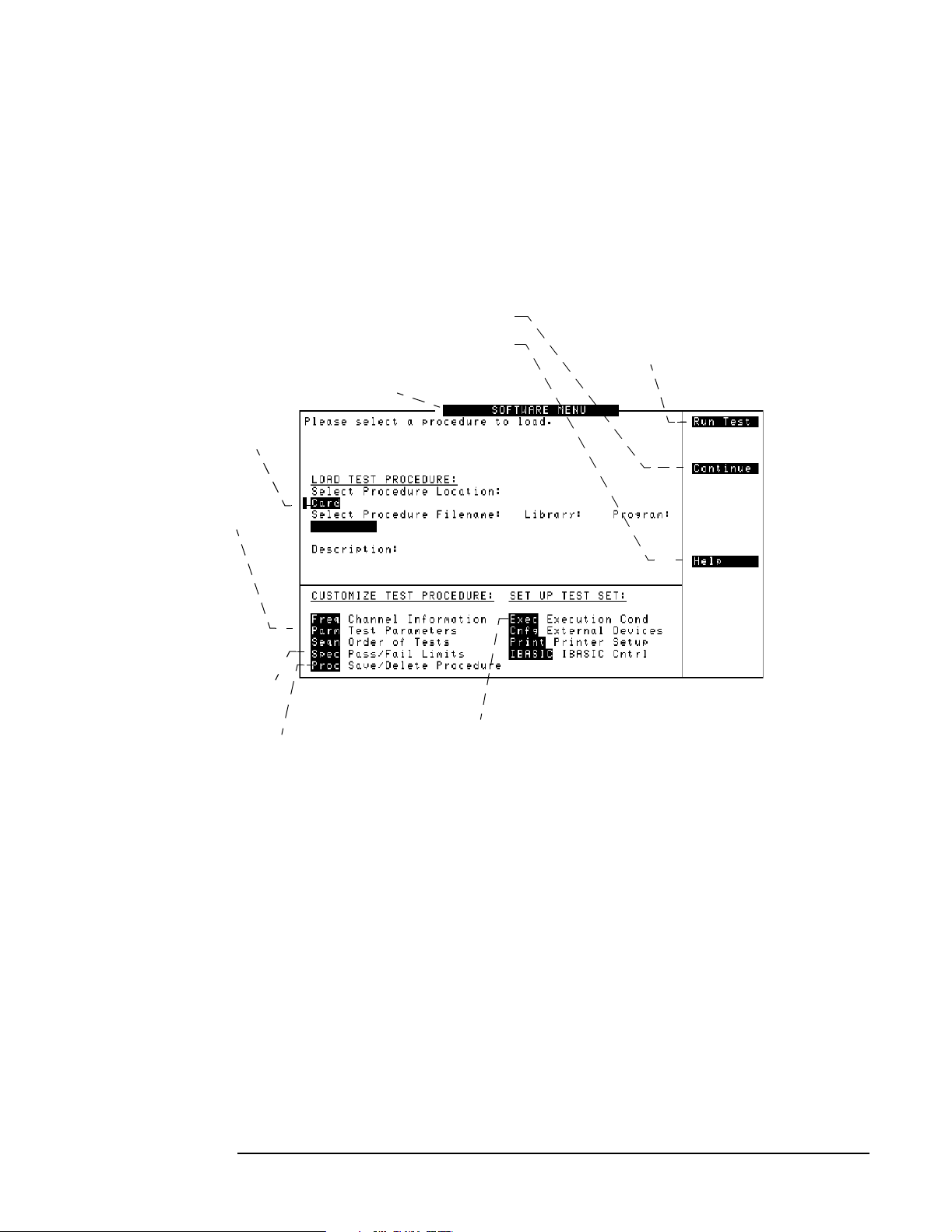
Reference
Accessing Test Software Functions
SOFTWARE MENU Screen Overview
Pressing the front-panel Menu key will cause the Test Set to display the SOFTWARE
MENU screen (see Figure 5-1). This screen allows the user to configure and run custom
Test Software, access help, proceed with a paused procedure, or access additional test
screens.
Figure 5-1 SOFTWARE MENU Screen
Continues a paused test.
Accesses the Test Set help screen.
Selects the menu list.
See “Loading a Test
Procedure” on page 91.
See “Changing Test
Parameters” on page 95.
Loads the T e st Software. The first time
might require as longs as 20 s econd s.
Once the Test Software is in internal
memory, it runs the test.
See “Changing
Pass/Fail Limits” on
page 98.
See “Saving/Deleting a
Procedure” on page 101.
Setting Test Execution
Conditions is not used in
the Test Software.
90
Chapter 5
O:\Manuals\E6385A_Cd ma \B ook\Referenc.fm
Page 89

Loading a Test Procedure
Before you begin testing, you must load the Test Software into the Test Set memory (see
Figure 5-2). To load the Test Software, select the location where the procedure currently
resides (in this case, it will be a PC card) and a procedure file name to download into the
Test Set memory. The card comes pre-programmed with at least one procedure.
The first time that you select a procedure, the actual Test Software program is not
loaded into the Test Set memory until you press the Test Set
take approximately 20 seconds for the Test Software program to load. The program will
remain in memory after a power-down/power-up cycle, unless it is manually deleted or a
new program is loaded.
Figure 5-2 Loading a Test Procedure
Selects the location
and file name of the
test procedure and its
associated library file.
Reference
Accessing Test Software Functions
k1 (Run Test) key. It will
Reference
NOTE See “Troubleshooting the Test Software Installation” on page 121 for some hints to help
debug any problems that you might have during the installation of the Test Software.
Chapter 5
91
Page 90
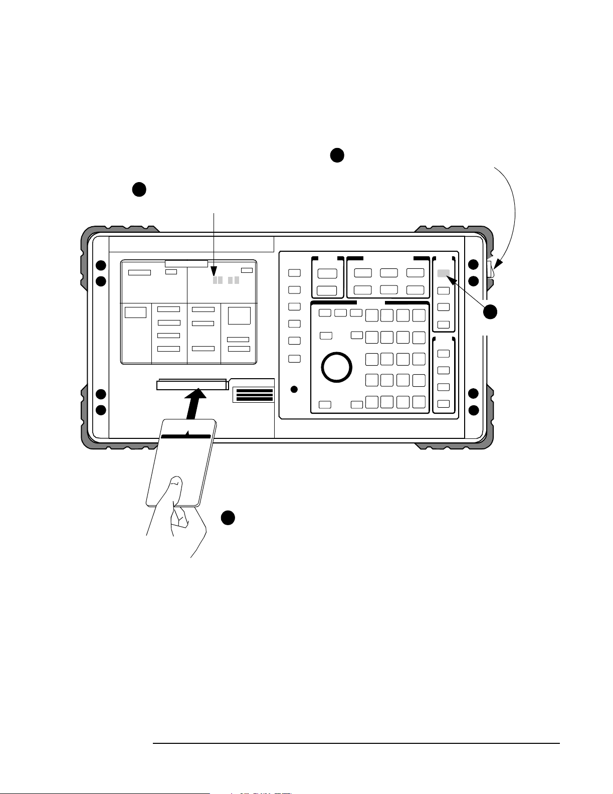
Reference
Accessing Test Software Functions
Loading the Test Software Card and Procedure
Load the Test Software card and a procedure as shown in Figure 5-3 and Figure 5-4.
Figure 5-3 Loading the Test Software Card
Wait until the first test screen is
2
displayed (about 45 seconds).
Turn the power o n. (The po wer switc h
1
is located above the power cord
connection on the right-side panel.)
- - - -
Menu
Insert the Test Software card.
3
4
Preset.Press
92
Chapter 5
O:\Manuals\E6385A_Cd ma \B ook\Referenc.fm
Page 91

Figure 5-4 Loading a Procedure
Reference
Accessing Test Software Functions
Press the Menu key to display
5
the SOFTWARE MENU screen.
Scroll to Card
7 8
and select it.
Scroll to Select Procedure Location:
6
and select it.
Scroll to Select Procedure Filename:
and select it.
Reference
Scroll to Choices: and select the
Procedure name: LCDMA.
DEMO
LCDMA
Scroll to Run Test and select it.
109
The Test Software will load.
Loading Time:
First time:
approximately
20 seconds.
After first time:
approximately
8 seconds.
Chapter 5
93
Page 92

Reference
Accessing Test Software Functions
Customizing a Test Procedure
Test Software packages have been designed so that you may make changes easily from
the Test Set front panel (see Figure 5-5). For example, you may insert or delete tests, and
later, after running the tests, you may change the pass/fail limits or decide to test
different channels. You may store the customized test procedure on an SRAM card so
that you may skip these steps in the future, see “Saving/Deleting a Procedure” on page
101.
Figure 5-5 Customizing a Test Procedure
The fields listed under
CUSTOMIZE TEST
PROCEDURE are used
to customize the Test
Software for various
testing requirements.
NOTE The Test Software package might not allow customization of testing procedures. If you
attempt to enter a customization screen that is not supported with the current package,
the message “Access to secure test information denied” will be displayed.
94
Chapter 5
O:\Manuals\E6385A_Cd ma \B ook\Referenc.fm
Page 93
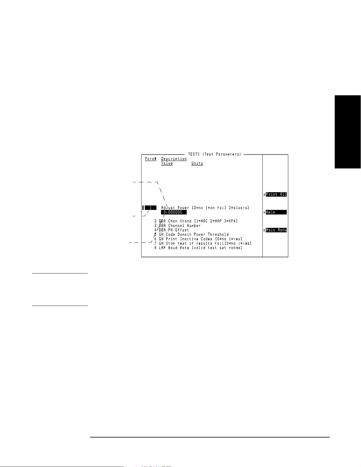
Reference
Accessing Test Software Functions
Changing Test Parameters
The Test Software uses parameters to optimize the test environment and conditions for
the testing situation. The default test parameters are determined by examining the test
requirements and specifications from the equipment manufacturer. The Test Software
comes with default settings for all test parameters.
Press the
Menu key, then select the Parm Test Parameters field to display the TESTS
(Test Parameters) screen (see Figure 5-6).
The fields in the TESTS (Test Parameters) screen allow you to change test parameters to
optimize the testing conditions (see Figure 5-7 and Figure 5-8). For information on
saving customized test parameters, see “Saving/Deleting a Procedure” on page 101.
Figure 5-6 TESTS (Test Parameters) Screen
Parameter description.
The descriptions for the
Test Software might be
different than shown here.
Selects the parameter
to be changed.
Displays the cu rrent
parameter setting.
Reference
NOTE The TESTS (Test Parameters) screen might not be used in the particular Test Software
package that you are using, or some fields might not be present, depending on the Test
Software application. The message “Access to secure test information denied” will be
displayed if the screen is not supported in the Test Software package.
Chapter 5
95
Page 94
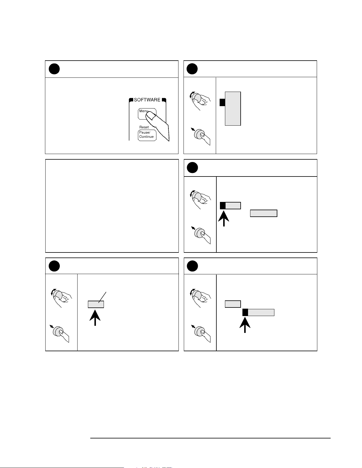
Reference
Accessing Test Software Functions
Figure 5-7 Changing Test Parameters
Press the Menu key to display t he
1
SOFTWARE MENU screen.
If the Test Software is running, press
Shift, Pause/Continue before
before
pressing Menu.
The TESTS (Test Parameters)
screen appears on the display.
Scroll to
2
and select it.
Position
Select
Scroll to Parm #
3
and select it.
Position
Select
Parm Test Parameters
Freq
Parm
Seqn
Spec
Proc
Channel Information
Test Parameters
Order of Tests
Pass Fail Limits
Save/Delete Procedure
(Entries on the display
might be different.)
1
Adjust Power [0=no 1=on f
0.00000
Scroll to the Parm # to be
4
changed and select it.
Scroll
Select
(This parameter number and
description are examples.)
15 MDM Flow Control [1=None
Scroll to Value
5
and select it.
Position
Select
15
MDM Flow Control [1=None
0.000000
Continue on next page
96
Chapter 5
O:\Manuals\E6385A_Cd ma \B ook\Referenc.fm
Page 95
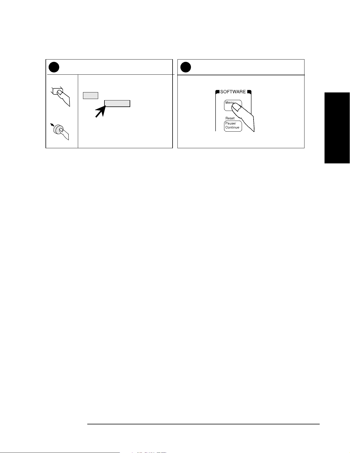
Figure 5-8 Changing Test Parameters (continued)
Reference
Accessing Test Software Functions
Use the DATA ENTRY keys to enter a
6
new
Select
Select
4
value, then se lect it.
15
MDM Flow Control [1=None
1.000000
Press the Me nu key to return to the
7
SOFTWARE MENU
screen
.
Reference
Chapter 5
97
Page 96

Reference
Accessing Test Software Functions
Changing Pass/Fail Limits
Pass/Fail limits define the values with which a measurement result is compared to
determine if the Base Station under test meets the specified standards. Default values
are set in the Test Software. These default values may be changed to suit particular
requirements.
Press the
Menu key, then select the Spec Pass/F ail Limi ts field to display the TESTS
(Pass/Fail Limits) screen (see Figure 5-9).
The fields in the TESTS (Pass/Fail Limits) screen allow you to change the pass/fail limits
to optimize the testing conditions (see Figure 5-10 and Figure 5-11). For information on
saving customized pass/fail limits, see “Saving/Deleting a Procedure” on page 101.
Figure 5-9 TESTS (Pass/Fail Limits) Screen
Selects the limit(s ) with which
to compare measured res ults.
Choices includes Upper,
Lower, and Both.
The descriptions for
the Test Software
might be different
than shown here.
Selects the pass/fail
limit to be edited.
Sets the lower or upper
pass/fail limits.
NOTE The TESTS (Pass/Fail Limits) screen might not be used in the particular Test Software
package that you are using, or some fields might not be present, depending on the Test
Software application. The message “Access to secure test information denied” will be
displayed if the screen is not supported in the Test Software package.
98
O:\Manuals\E6385A_Cd ma \B ook\Referenc.fm
Chapter 5
Page 97

Figure 5-10 Changing Pass/Fail Limits
Reference
Accessing Test Software Functions
Press the Menu key to displ ay the
1
SOFTWARE MENU screen.
If the Test Software is running, press
Shift, Pause/Continue
pressing Menu.
The TESTS (Pass/Fail Limits)
screen appears on the display.
before
Scroll to Spec Pass/Fail Limits
2
and select it.
Position
Select
Scroll to Spec #
3
and select it.
Position
Select
Freq
Parm
Seqn
Spec
Proc
Channel Information
Test Parameters
Order of Tests
Pass/Fail Limits
Save/Delete Procedure
(Disregard this number.)
Reference
1
Scroll to the desired Spec #
4
and select it.
Scroll
Select
(This Spec # is an example.)
6
Output Power Adjustment
--1.000000
1.000000
Scroll to Lower Limit
5
and select it.
Position
Select
6
Output Power Adjustment
--1.000000
1.000000
Continue on next page
Chapter 5
99
Page 98

Reference
Accessing Test Software Functions
Figure 5-11 Changing Pass/Fail Limits (continued)
Use the DATA E NTRY k eys to e nter a
6
Enter
Select
8
Enter
Select
value, then se lect it.
new
6
Use the DATA E NTRY k eys to e nter a
value, then select it.
new
Output Power Adjustment
.500000
Output Power Adjustment
-0.500000
(Enter the desired value.)
0.500000
(Enter the desired value.)
dB
1.000000
Scroll to Upper Limit
7
and select it.
Position
Output Power Adjustment
.500000
Select
Scroll to Check
9
and select it.
Position
Select
1.000000
Both
dB
Select the choic e that should apply
10
to testing and select it. SOFTWARE MENU screen.
Position
Choices:
Upper
Lower
Select
Both
None
Press the Menu key to return to the
11
Position
Select
100
Chapter 5
O:\Manuals\E6385A_Cd ma \B ook\Referenc.fm
Page 99

Reference
Accessing Test Software Functions
Saving/Deleting a Procedure
A test procedure is a collection of channel information, test parameters, testing order,
and pass/fail limits saved in a file that customizes the Test Software to a specific
application. Ordinarily, procedures are saved on an SRAM card.
Press the
TESTS (Save/Delete Procedure) screen (see Figure 5-12).
The fields in the TESTS (Save/Delete Procedure) screen allow you to save or delete
procedures (see Figure 5-13, Figure 5-14, and Figure 5-15). When you save a procedure,
you save channel information, test parameters, pass/fail limits, and testing order, plus a
library that contains the names of all test parameters, pass/fail limits, and tests that are
resident in the Test Software. The library file comes from the Test Software and cannot
be modified. The library file will be automatically saved on the card that is being used to
store the new test procedure.
The process for deleting a procedure is the same as saving a procedure, except that, in
Step13, select the Del Proc field instead.
Figure 5-12 TESTS (Save/Delete Procedure) Screen
Menu key, then select the Proc Save/Delete Proced ure field to display the
Reference
Chapter 5
101
Page 100

Reference
Accessing Test Software Functions
Figure 5-13 Saving a Test Procedure
Press the Menu key to display the
1
SOFTWARE MENU scree n.
If the Test Software is running, press
Shift, Pause/Continue before
pressing Menu.
The TESTS (Save/Delete Procedure)
screen appears on the Test Set display.
Scroll to Proc Save/Delete Procedu re
2
and select it.
Position
Freq
Parm
Seqn
Select
Scroll to Select Procedure Location:
3
and select it.
Position
Select
Spec
Proc
Select Procedure Location:
Channel Information
Test Parameters
Order of Tests
Pass Fall Limits
Save/Delete Procedure
Scroll to Card
4
and select it.
Position
Select
Choices:
Card
RAM
Disk
(You may also save procedures
to an internal RAM disk.)
Insert an initial ized PC card
5
into the front-pa nel card slot.
For detailed SRAM card
initialization instructions, see
“Initializing a PC Card” on
page 118.
Continue on next page
102
Chapter 5
O:\Manuals\E6385A_Cd ma \B ook\Referenc.fm
 Loading...