

Page 1

Agilent E5810A
LAN/GPIB Gateway for Windows
®
User’s Guide
Page 2

THIS PAGE HAS BEEN INTENTIONALLY LEFT BLANK.
Page 3

Front Matter
Notice
The information contained in this document is subject to change without
notice.
Agilent Technologies shall not be liable for any errors contained in this
document. Agilent Technologies makes no warranties of any kind with
regard to this document, whether express or implied. Agilent Technologies
specifically disclaims the implied warranties of merchantability and fitness
for a particular purpose. Agilent Technologies shall not be liable for any
direct, indirect, special, incidental, or consequential damages, whether
based on contract, tort, or any other legal theory, in connection with the
furnishing of this document or the use of the information in this document.
Warranty Information
A copy of the specific warranty terms applicable to your Agilent Technologies
product and replacement parts (as applicable) is shipped with your product.
If the warranty terms are not included or if you want a copy
of the warranty terms, contact Agilent Technologies, Inc.
U.S. Government Restricted Rights
The Software and Documentation have been developed entirely at private
expense. They are delivered and licensed as "commercial computer
software" as defined in DFARS 252.227- 7013 (Oct 1988), DFARS 252.2117015 (May 1991) or DFARS 252.227-7014 (Jun 1995), as a "commercial
item" as defined in FAR 2.101(a), or as "Restricted computer software" as
defined in FAR 52.227-19 (Jun 1987) (or any equivalent agency regulation
or contract clause), whichever is applicable. You have only those rights
provided for such Software and Documentation by the applicable FAR or
DFARS clause or the Agilent standard software agreement for the product
involved.
3
Page 4

Declaration of Conformity
The Declaration of Conformity (DoC) for this instrument is available on the
Agilent Web site. You can search the DoC by its product model or
description at the Web address below.
http://regulations.corporate.agilent.com/DoC/search.htm
NOTE
If you are unable to search for the respective DoC, please contact your
local Agilent representative.
4
Page 5

ICES Statement
Instruction manual symbol affixed to
product. Indicates that the user must
refer to the manual for specific
WARNING or CAUTION information to
avoid personal injury or damage to the
product.
Indicates the field wiring terminal that
must be connected to earth ground
before operating the equipment —
protects against electrical shock in
case of fault.
Frame or chassis ground terminal—
typically connects to the equipment's
metal frame
Alternating current (AC).
Direct current (DC).
Warning. Risk of electrical shock.
Calls attention to a procedure,
practice, or condition that could cause
bodily injury or death.
Calls attention to a procedure,
practice, or condition that could
possibly cause damage to equipment
or permanent loss of data.
or
WARNING
CAUTION
This ISM device complies with Canadian ICES-001.
Cet appareil ISM est conforme à la norme NMB-001 du Canada.
Safety Symbols
WARNINGS
The following general safety precautions must be observed during all
phases of operation, service, and repair of this product. Failure to comply
with these precautions or with specific warnings elsewhere in this manual
violates safety standards of design, manufacture, and intended use of the
product. Agilent Technologies assumes no liability for the customer's failure
to comply with these requirements.
Ground the equipment: For Safety Class 1 equipment (equipment having a
protective earth terminal), an uninterruptible safety earth ground must be
provided from the mains power source to the product input wiring terminals
or supplied power cable.
DO NOT operate the product in an explosive atmosphere or in the presence of
flammable gases or fumes.
For continued protection against fire, replace the line fuse(s) only with
fuse(s) of the same voltage and current rating and type. DO NOT use
repaired fuses or short-circuited fuse holders.
5
Page 6

Keep away from live circuits: Operating personnel must not remove
equipment covers or shields. Procedures involving the removal of covers or
shields are for use by service-trained personnel only. Under certain
conditions, dangerous voltages may exist even with the equipment switched
off. To avoid dangerous electrical shock, DO NOT perform procedures
involving cover or shield removal unless you are qualified to do so.
DO NOT operate damaged equipment: Whenever it is possible that the safety
protection features built into this product have been impaired, either through
physical damage, excessive moisture, or any other reason, REMOVE
POWER and do not use the product until safe operation can be verified by
service-trained personnel. If necessary, return the product to Agilent for
service and repair to ensure that safety features are maintained.
DO NOT service or adjust alone: Do not attempt internal service or
adjustment unless another person, capable of rendering first aid and
resuscitation, is present.
DO NOT substitute parts or modify equipment: Because of the danger of
introducing additional hazards, do not install substitute parts or perform any
unauthorized modification to the product. Return the product to Agilent for
service and repair to ensure that safety features are maintained.
Documentation History
All Editions and Updates of this manual and their creation date are listed
below. The first Edition of the manual is Edition 1. The Edition number
increments by 1 whenever the manual is revised. Updates, which are issued
between Editions, contain replacement pages to correct or add additional
information to the current Edition of the manual. Whenever a new Edition is
created, it will contain all of the Update information for the previous Edition.
Each new Edition or Update also includes a revised copy of this
documentation history page.
Edition 1. . . . . . . . . . . . . . . . . . . . . . . . . . . . . . . . . . . . . May 2002
Edition 2. . . . . . . . . . . . . . . . . . . . . . . . . . . . . . . . . . . . . December 2003
Edition 3. . . . . . . . . . . . . . . . . . . . . . . . . . . . . . . . . . . . . May 2004
Edition 4. . . . . . . . . . . . . . . . . . . . . . . . . . . . . . . . . . . . . January 2005
Edition 5. . . . . . . . . . . . . . . . . . . . . . . . . . . . . . . . . . . . . September 2007
Edition 6. . . . . . . . . . . . . . . . . . . . . . . . . . . . . . . . . . . . . June 19, 2009
Edition 7. . . . . . . . . . . . . . . . . . . . . . . . . . . . . . . . . . . . . July 20, 2009
Edition 8. . . . . . . . . . . . . . . . . . . . . . . . . . . . . . . . . . . . . August 4, 2011
Edition 9. . . . . . . . . . . . . . . . . . . . . . . . . . . . . . . . . . . . . January 1, 2012
Edition 10. . . . . . . . . . . . . . . . . . . . . . . . . . . . . . . . . . . . September 24, 2012
6
Page 7

Edition 11 . . . . . . . . . . . . . . . . . . . . . . . . . . . . . . . . . . . March 19, 2013
Copyright Information
Agilent Technologies
E5810A LAN/GPIB Gateway for Windows User’s Guide
Copyright © 2002–2013 Agilent Technologies, Inc. All rights reserved.
Manual Part Number: E5810-90001
Trademark Information
Windows is a trademark or registered trademark of Microsoft Corporation in
the United States and/or other countries.
Support Information
Support information for the E5810A LAN/GPIB Gateway for Windows
follows. When calling Agilent with support questions, please have the
following information available so we can provide you with a quicker solution
to the problem.
E5810A Serial Number (printed on bottom of the unit and displayed
on the
Description of the Problem
Corrective actions already tried (see Chapter 4 - Troubleshooting
Information for suggested troubleshooting tips)
Welcome page of the E5810A Web access)
Contacting Agilent You can reach Agilent Technologies at this telephone number in the
Americas:
Americas Call Center: 1-800-829-4444
For other countries, contact your country’s Agilent support
organization. A list of contact information for other countries is
available on the Agilent Internet site:
www.agilent.com/find/assist
A list of other Agilent Web sites follows.
7
Page 8

URL Description
www.agilent.com/find/assist Agilent Technologies “Contact us” page
www.agilent.com/find/e5810a The latest E5810A product information with links to key
Web sites such as FAQs, Data Sheets, etc.
www.agilent.com/find/iolib Update the Agilent IO Libraries Suite software
www.agilent.com/find/techsupport The latest customer support information
www.agilent.com/find/ADN Connectivity resources all in one place
www.agilent.com/find/manuals Technical support information, including manuals,
application notes, FAQs, and software and firmware
downloads
www.agilent.com/find/connectivity For connection, communication and control of test
instruments from your computer, you can find out the
latest in the world of connectivity.
User’s Guide Information
This Agilent E5810A LAN/GPIB Gateway for Windows User’s Guide
describes installation, configuration, and use of an E5810A LAN/GPIB
Gateway for Windows that is connected to an Enterprise (corporate)
network, to a Local Network, or directly to a PC.
NOTE
All Agilent IO Libraries information in this guide refers to
Agilent IO Libraries Suite version 15.0 or above. For specific information
on other versions of the Agilent IO Libraries or Agilent IO Libraries Suite,
see the documentation for that version. You can download both updates
and older versions (for backward compatibility) of the IO Libraries
software at http://www.agilent.com/find/iolib.
8
Page 9

What’s in This
Guide?
A listing of the guide contents follows.
NOTE
This guide is NOT a tutorial on Local Area Networks (LANs) or specific
LAN operation. Consult your Information Technology (IT) department for
LAN specifics for your application.
Chapter Description
Chapter 1, “E5810A
Description,”
Chapter 2, “Installing the
E5810A,”
Chapter 3, “Using E5810A Web
Access,”
Chapter 4, “Troubleshooting
Information,”
Appendix A, “E5810A
Specifications,”
Appendix B, “Using the Telnet
Utility,”
“Glossary” Defines some of the technical terms used in this guide.
Accessing an
Electronic Copy of
This Guide
There are three ways you can access an electronic (.pdf) version of this
guide, as follows. You will need Adobe Acrobat Reader Version 3.0 or later
to view the electronic version.
Describes the E5810A, including hardware description and
network operation.
Shows how to install the E5810A and the
Agilent IO Libraries Suite.
Shows how to use the E5810A Web access to interface with
the E5810A from your PC.
Shows some ways to troubleshoot the E5810A, including
front panel, network, PC client, and instrument checks.
Provides specifications for the E5810A.
Provides a summary of using the Telnet utility.
Access From the E5810A Web Access. After the E5810A is installed,
you can access an electronic version of the manual by going to the
Welcome page and clicking User’s Guide (under the E5810A
Documentation
heading).
Access from the IO Control. If the Agilent IO Libraries Suite is
installed, a blue circled IO icon appears on the right hand side of the
Windows toolbar. To access an electronic version of this guide, click
the IO icon, then click
GPIB Users Guide
Documentation and then click E5810A LAN/
.
9
Page 10

Access from the Web. On your Web browser address line, type:
www.agilent.com/find/manuals and navigate to the E5810A
manual.
E5810A Related
Documentation
Product Related Documentation
Agilent IO
Libraries Suite
VISA To use the E5810A with VISA, you must configure a remote interface (also
SICL To develop and use SICL I/O applications for the E5810A in Windows,
T&M Toolkit To develop programs in Visual Studio .NET, see the Agilent T&M Toolkit
Suggested documentation you can use for E5810A LAN/GPIB Gateway for
Windows operation with the listed I/O application software products follow.
After the Agilent IO Libraries Suite has been installed on your PC, .pdf files
of the Agilent IO Libraries Suite documentation including VISA and SICL
User’s Guides are available. Click the blue IO icon on the Windows taskbar
and then click Documentation.
The Agilent IO Libraries Suite Getting Started Guide and the IO Libraries
Suite Online Help describe the use of the IO Libraries Suite.
known as VISA LAN Client operation). To develop and use VISA applications
for the E5810A, see the Agilent VISA User’s Guide.
see the Agilent SICL User’s Guide for Windows.
product. Information is available at www.agilent.com/find/toolkit.
10
Page 11

Table of Contents
1 E5810A Description
E5810 Hardware Description ....................................................... 15
Typical Network Connections ............................................... 15
Front Panel Features ............................................................ 17
Rear Panel Features ............................................................ 21
Rack Mount Kit (Optional) .................................................... 21
E5810A Software/Firmware ......................................................... 22
E5810A Operating Features ................................................. 23
Typical Network Operation ................................................... 24
Software/Firmware Architecture ........................................... 25
Typical Network IP Addressing ............................................ 27
Communicating with the E5810A ......................................... 29
2 Installing the E5810A
Installation Flowchart ................................................................... 35
Before You Install the E5810A..................................................... 37
Check Shipment Items ......................................................... 37
Rack-Mount the E5810 (Optional) ........................................ 38
Getting Network Information ........................................................ 39
Getting Enterprise Network Information ............................... 39
Getting Local Network Information ....................................... 39
Configuring the E5810A on a Local Network............................... 41
What is a Local Network? ..................................................... 41
Connecting the E5810A to a Local Network ......................... 43
Configuring the E5810A for Local Network Operation ......... 46
Installing the E5810A on an Enterprise Network ......................... 52
Connecting the E5810 to the Network .................................. 52
Configuring the E5810A for Enterprise Network Operation .. 53
Verifying Instrument Communication........................................... 58
Open the Instrument Page ................................................... 58
Instrument Page Functions .................................................. 59
Installing and Configuring Agilent IO Libraries Suite.................... 61
Configuring a Remote GPIB Interface .................................. 63
Configuring a Remote Serial Interface ................................. 65
Verifying Communication From Your PC ............................. 68
Programming Instruments .................................................... 69
3 Using E5810A Web Access
Opening Your Web Browser for E5810A Web Access ................ 75
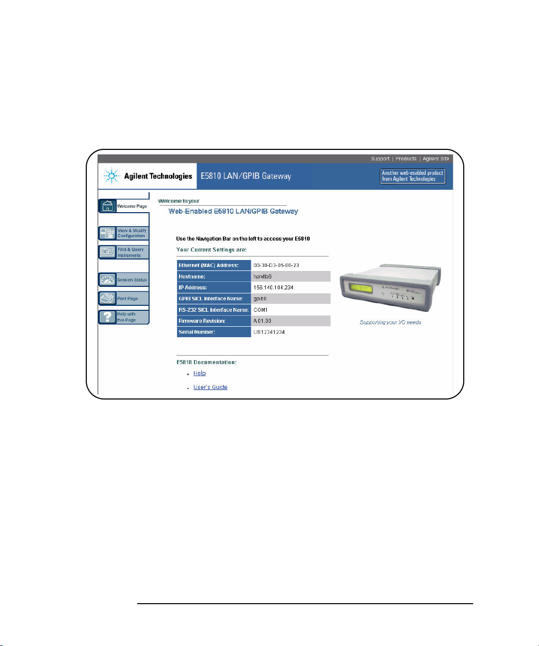
Using the Welcome Page ............................................................ 76
Navigation Bar ...................................................................... 77
E5810A Current Settings ...................................................... 78
Table of Contents 11
Page 12

E5810A Support Information ................................................. 79
E5810A Documentation ........................................................80
Viewing and Modifying Configuration ........................................... 81
Viewing E5810A Configuration .............................................81
Modifying E5810A Configuration ..........................................82
Finding and Querying Instruments ...............................................92
Finding Instruments ..............................................................93
Querying Instruments ............................................................94
Other Web Access Functions .......................................................97
Determining Session Status .................................................. 97
Using Web Help .................................................................... 98
Updating E5810A Firmware ..................................................99
4 Troubleshooting Information
Troubleshooting Overview..........................................................109
Checking the E5810A................................................................. 110
Checking Front and Rear Panel Displays ........................... 110
Checking E5810A Parameters ............................................ 113
Checking the Network ................................................................ 114
Network Configuration Problems Summary ........................ 114
Checking Web Browser Settings ........................................ 115
Checking Other Network Problems ..................................... 117
Checking PC Client Connections ............................................... 119
Verifying PC Client Connections ......................................... 119
Checking syslog Messages ................................................ 121
Runtime Error Messages .................................................... 124
Checking Instruments.................................................................127
Checking GPIB Instruments ................................................127
Checking RS-232 Instruments ............................................ 128
A E5810A Specifications
Specifications and Supplementary Information ..........................131
Supported Network Protocols..................................................... 134
B Using the Telnet Utility
Using the Telnet Utility................................................................ 137
Telnet Commands for the E5810A .............................................140
Glossary
12 Table of Contents
Page 13

1
E5810A Description
Page 14

E5810A Description
This chapter gives guidelines to install, configure, and troubleshoot the
E5810A LAN/GPIB Gateway for Windows (E5810) for use with supported,
network-equipped computer systems, including:
E5810 Hardware Description
E5810 Software/Firmware
14 Chapter 1
Page 15
E5810A Description
LAN GPIB RS232
E5810
Typically Router
or Switch
GPIB Instruments
To RS-232
Instrument
LAN
Patch
Cables
GPIB
GPIB
GPIB
Enterprise Network Connections
To Enterprise
Network
GPIB Ports
E5810 Hardware Description
E5810 Hardware Description
The E5810 LAN/GPIB Gateway for Windows provides a gateway between
network-equipped computer systems and GPIB and/or RS-232 based
instruments. This section provides an overview of E5810 hardware,
including:
Typical Network Connections
Front Panel Features
Rear Panel Features
Power-On and Default Settings
Rack Mount Kit (Optional)
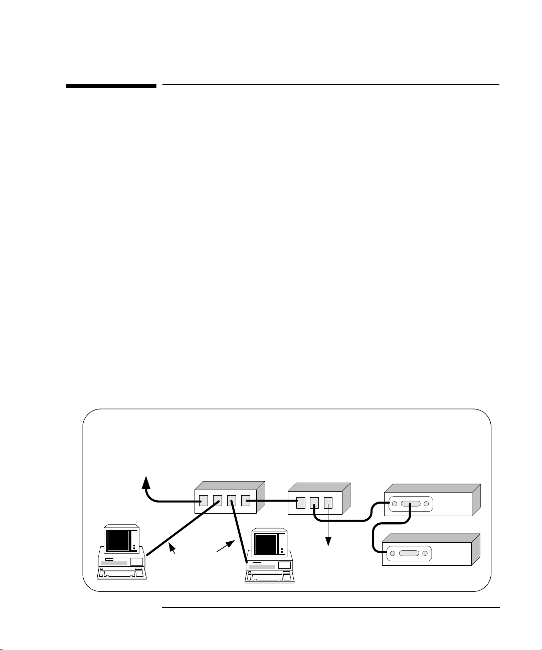
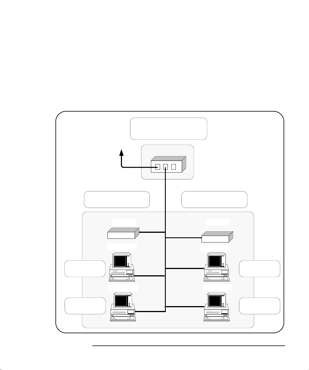
Typical Network Connections
The E5810 can be connected to an Enterprise (corporate) network, to a
Local network (isolated LAN), or directly to a PC and can be connected to
as many as 14 GPIB instruments and/or to one RS-232 instrument. The
E5810 allows I/O applications to obtain measurement data either locally or
remotely from GPIB and/or RS-232 instrumentation. The following figures
show typical network and direct PC connections to an E5810.
Enterprise Network
Connections
In a typical Enterprise (corporate) network, the E5810 is connected to the
network by a router or switch. For this configuration, the E5810 is visible to
the Enterprise network.
Chapter 1 15
Page 16
E5810A Description
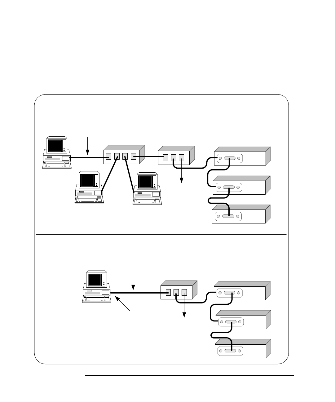
Local Network Connections (Multiple PCs can Communicate with the E5810)
LAN GPIB RS232
E5810
Typically Hub
or Switch
GPIB Instruments
To RS-232
Instrument
LAN Patch
Cable
GPIB
GPIB
GPIB
GPIB
LAN GPIB RS232
E5810
GPIB Instruments
To RS-232
Instrument
Crossover
Cable
GPIB
GPIB
GPIB
GPIB
Direct PC Connection (Only One PC can Communicate with the E5810)
Connect to
PC LAN Card
E5810 Hardware Description
Local Network
Connections
Typically, a hub or switch is used for local network configuration. A cable/
DSL router may be used to provide a DHCP Server. For typical direct
connections from a PC to the E5810, a
crossover cable is connected from
the E5810 LAN port to a LAN card on the PC. For Local Network or direct
PC connections, the E5810 is not visible on the Enterprise network.
16 Chapter 1
Page 17
E5810A Description
Activity
LAN GPIB RS232
Power Fault
Preset
E5810A
LAN/GPIB Gateway
agiltb6
169.254.58.10
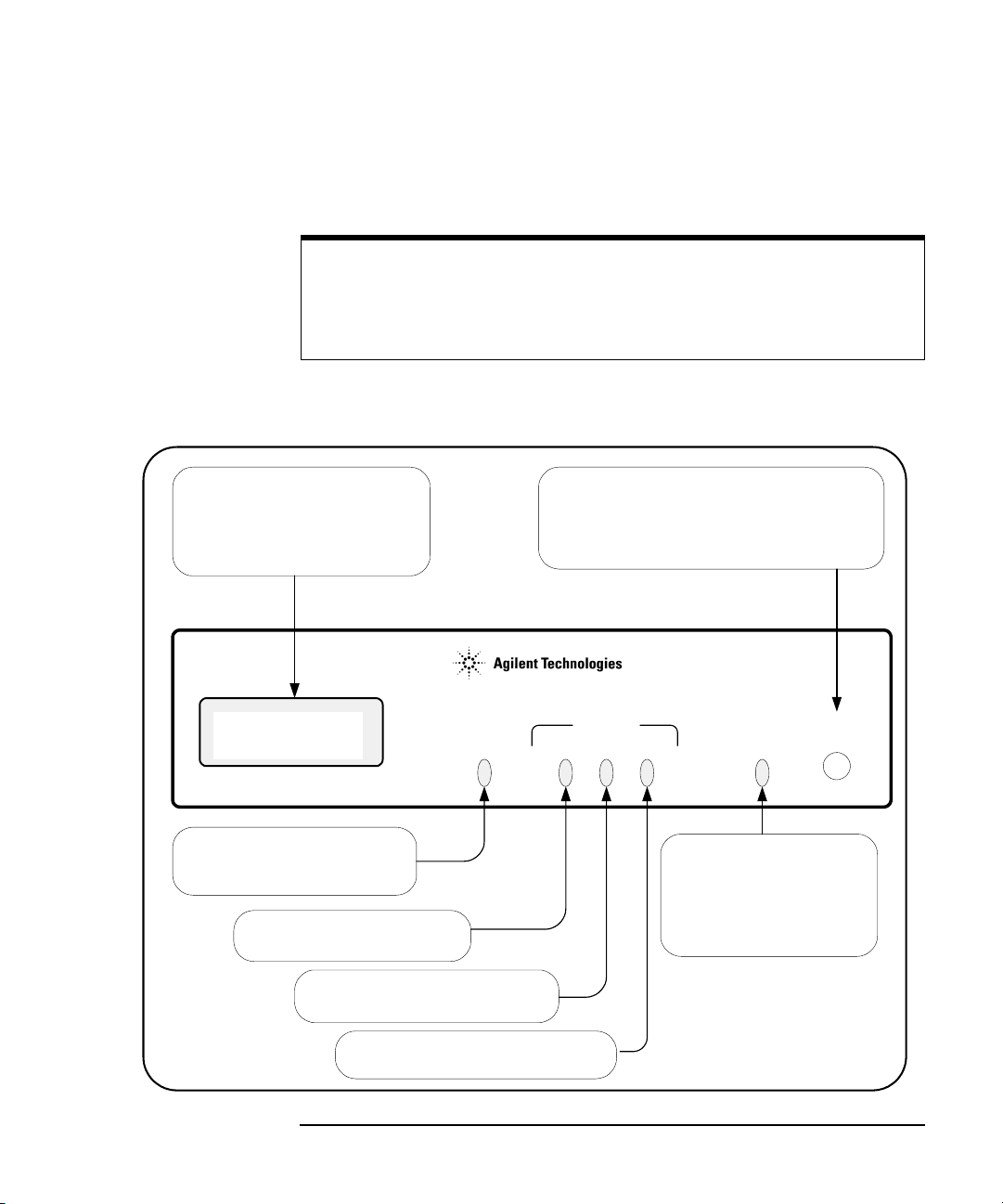
Display
A 16-character, two-line display
that displays the Hostname (if
known) and the IP Address plus
system messages.
Power LED
When ON (Green), shows AC
power is applied to the E5810.
LAN LED
Flashes for activity on the LAN.
GPIB LED
Flashes for GPIB instrument activity.
Fault LED
If ON (RED) for >10 sec,
indicates possible hardware
failure. Briefly turns ON at
power-on while the E5810
is running its self-test.
Preset Button
Depressing for <10 sec temporarily resets only
the default password (E5810). Depressing for
>10 sec resets all parameters to factory default
values and reboots the E5810.
RS232 LED
Flashes for RS-232 instrument activity.
E5810 Hardware Description
Front Panel Features
This section describes the E5810 front panel features,
NOTE
The Hostname, if detected, is displayed on the first line of the E5810 front
panel display. The IP Address of the E5810 is displayed on the second
line of the E5810 front panel display.
Front Panel
Display/LEDs
This figure shows E5810 front panel functions.
Chapter 1 17
Page 18
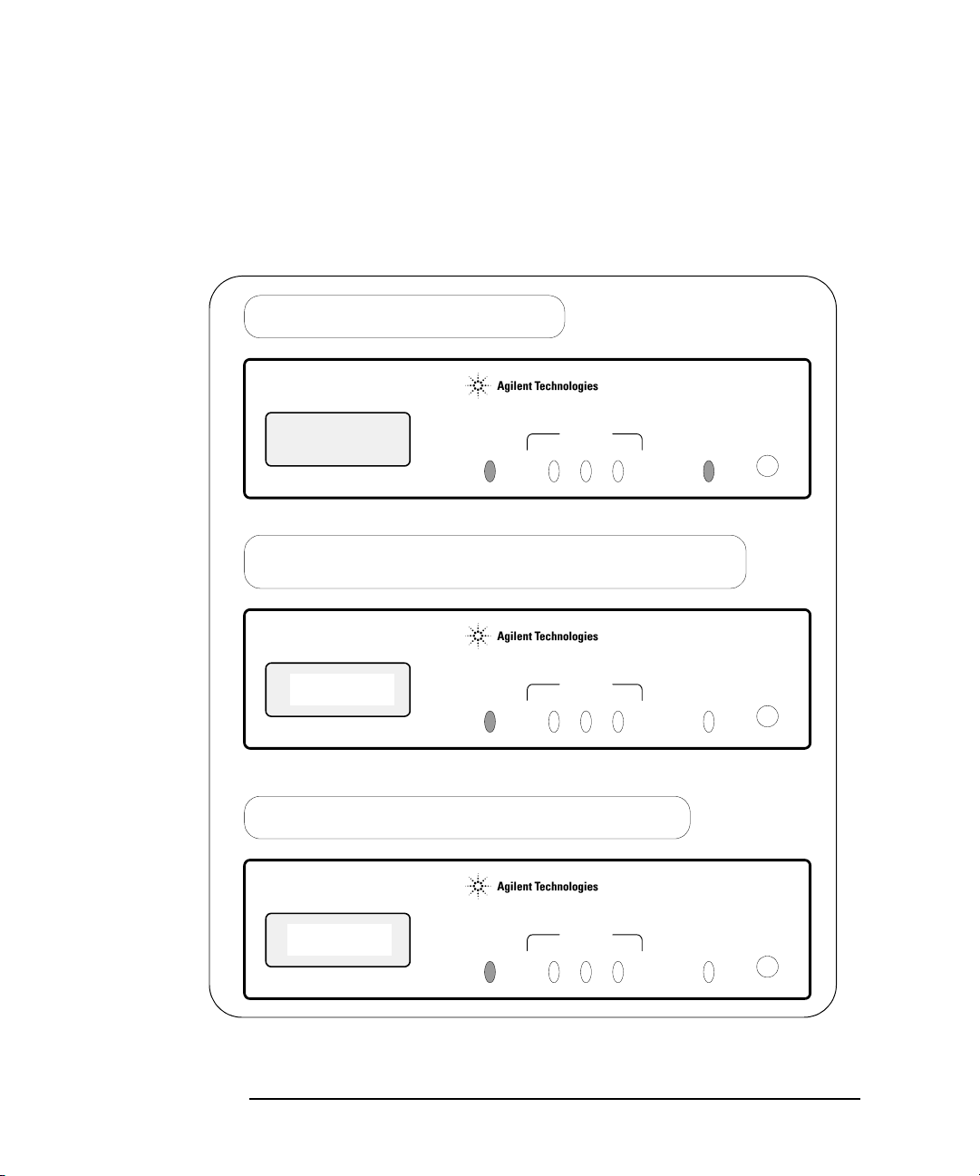
E5810A Description
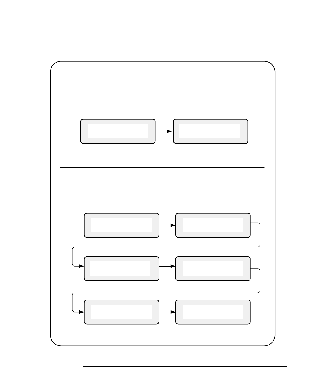
Power Applied
Display is blank, Power (Green) and Fault (Red) are ON.
169.254.58.10
Activity
LAN GPIB RS232
Power Fault
Preset
E5810A
LAN/GPIB Gateway
Activity
LAN GPIB RS232
Power Fault
Preset
E5810A
LAN/GPIB Gateway
Searching for DHCP Server
Display displays message, Power (Green) is ON and Fault (Red) is OFF. This typically takes
20 to 30 seconds and can take up to 150 seconds if a DHCP Server is not present.
Searching for
DHCP Server...
IP Address and Hostname Displayed
Display displays Hostname, (if known) and IP address, only Power (Green) is ON.
Activity
LAN GPIB RS232
Power Fault
Preset
E5810A
LAN/GPIB Gateway
Hostname
IP Address
E5810 Hardware Description
Typical Power-On
Sequence
This figure shows major steps in a typical power-on sequence for an E5810
that is connected to a network that supports Dynamic Host Configuration
Protocol (DHCP) and Domain Name Service (DNS). If the network does not
support DHCP and/or DNS, the power-on sequence may be different than
that shown.
18 Chapter 1
Page 19

E5810A Description
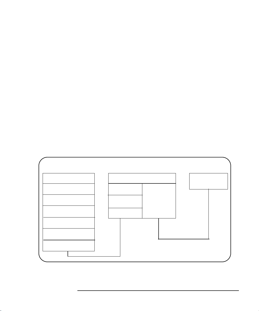
E5810 Hardware Description
Power-On (Default)
Settings
Parameter Default Parameter Default
DHCP: ON GPIB Address: 21
IP Address: 169.254.58.10 GPIB Logical Unit: 7
Subnet Mask: 255.255.0.0 RS-232 SICL Interface Name: COM1
Default Gateway: 0.0.0.0 RS-232 Baud Rate: 9600
DNS Server(s): 0.0.0.0 RS-232 Parity: NONE
Hostname: none RS-232 Bits: 8
Description: Agilent E5810
Universal Plug & Play: ON RS-232 Flow Control: NONE
LAN Keepalive (sec): 7200 sec RS-232 SRQ: RI
When power is first applied to the E5810 and the hardware self-test has
completed, the E5810 is initialized to the factory-set default configuration.
This table shows the default configuration parameter settings for the E5810.
The E5810 uses these default configuration values until you set any other
configuration values. The E5810 also uses these values when you press the
Preset button and hold it down for >10 seconds. See Chapter 3, “Using
E5810A Web Access” for a description of each parameter.
RS-232 Stop Bits: 1
<MAC Addr>
I/O Timeout (sec): 120 sec Password E5810
GPIB SICL Interface Name: gpib0
Preset Button
Operation
The Preset button on the front panel of the E5810 is used to reset the E5810
to its default configuration values (preset at the factory). As shown in the
figure on the next page, the
Preset button has two modes of operation:
If you depress the Preset button and release it in <10 seconds, only
the E5810 password is temporarily changed and is reset to its
default value (E5810). If you cycle power or reboot the E5810, the
E5810 will return to the actual password that was previously set. All
existing configuration values remain unchanged.
If you depress and hold the Preset button for 10 seconds or more, all
configuration values are reset to their factory default values and the
E5810 is rebooted. All network connections to the E5810, if any, are
also terminated without any cleanups.
Chapter 1 19
Page 20
E5810A Description
Depress and Hold the Preset Button (>10 Seconds)**
Hostname
IP Address
Temporary Pass-
word = "E5810"
Hostname
IP Address
Hold to Reboot
& Set Defaults
Setting Factory
Defaults
Rebooting
E5810...
Depress and Quickly (<10 seconds) Release the Preset Button *
- The E5810 password is temporarily reset to its factory default (E5810).
- All other configuration parameters remain unchanged.
- This state is maintained until the next time the E5810 is booted.
- The front panel display sequence is as follows.
* Release the Preset button when Temporary Password = "E5810" is displayed.
Hostname
IP Address
Temporary Pass-
word = "E5810"
- All configuration parameters are set to their default values.
- The E5810 is rebooted.
- The front panel display sequence is as follows.
** Release the Preset button when Rebooting E5810... is displayed.
E5810 Hardware Description
20 Chapter 1
Page 21
E5810 Hardware Description
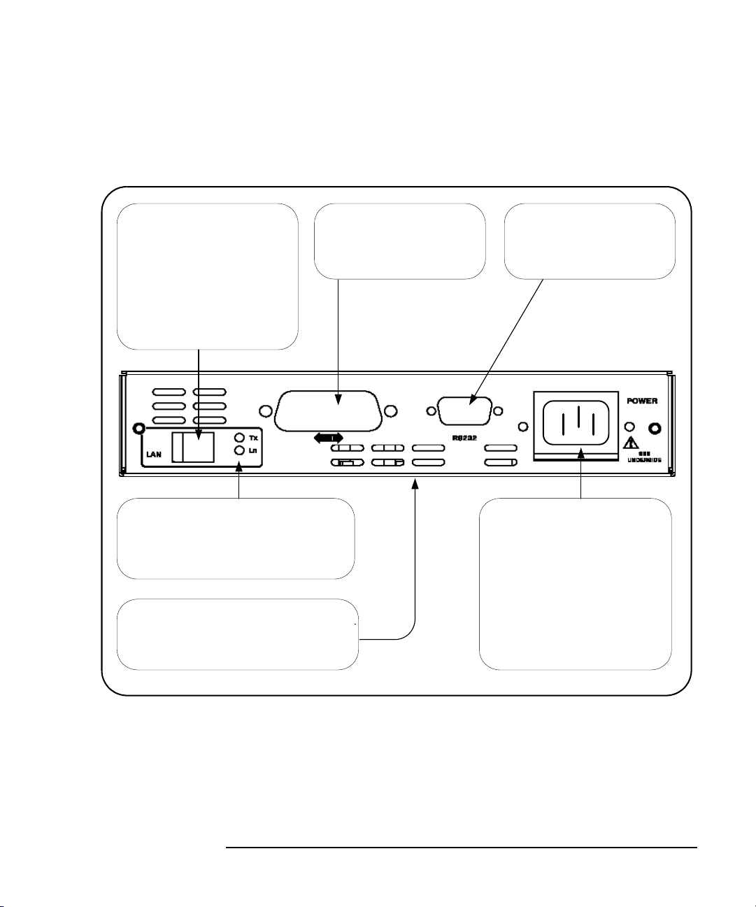
GPIB Port
Connect one end of GPIB
cable to this port and connect
other end of cable to a GPIB
instrument.
RS232 Port
Connect one end of RS-232
cable to this port and connect
other end of cable to an
RS-232 instrument.
LAN Port
Connect one end of a LAN patch
cable to this port and connect
the other end of the cable to a
router/hub/switch.
OR
Connect one end of a crossover
cable to this port and the other
end of the cable to a LAN card
on your PC.
LAN Activity Lights
When the green Ln light is ON, the E5810
is successfully connected to the LAN. When
the green Tx light flashes, the E5810 is
transmitting data onto the LAN.
POWER Port
Connect AC power cord to this
port and plug cord into an AC
outlet. The E5810 does not
have a power switch. The Mains
disconnect is to unplug the AC
power cord from the AC outlet.
The power supply automatically
conforms to the input voltage
and frequency supplied, within
100V - 240V (±10%) @ 47-63 Hz.
Serial Number and Ethernet Address
The E5810 Serial Number and Ethernet
(MAC) Address are printed on a label on
the underside of the E5810.
Rear Panel Features
This figure shows the rear panel features of the E5810.
E5810A Description
Rack Mount Kit (Optional)
As desired, you can mount up to two E5810 in a standard EIA rack using the
E5810 Rack Mount Kit (E5810 Opt 100 or E5810-00100). The E5810 is one
standard half-rack unit wide and one standard rack unit high. See the
E5810-00100 Rack Mount Kit for installation instructions.
Chapter 1 21
Page 22

E5810A Description
E5810A Software/Firmware
E5810A Software/Firmware
The E5810 LAN/GPIB Gateway for Windows provides an interface
(gateway) that allows networked computers to talk or listen to GPIB and/or
RS-232 devices via Local Area Network (LAN) connections. The E5810
connects a network (Enterprise or Local) from PCs with Windows XP/Vista/
7/8/Server 2008 R2 to GPIB and/or RS-232 instruments. This section
describes E5810 software/firmware features, including:
E5810 Operating Features
Typical Network Operation
Software/Firmware Architecture
Typical Network IP Addressing
Communicating with the E5810
22 Chapter 1
Page 23

E5810A Operating Features
Feature Description
E5810A Description
E5810A Software/Firmware
Remote access to
instruments via LAN
I/O Software Included The E5810 includes the Agilent IO Libraries Suite, which includes
Supports DHCP
Protocol
Access and control up to 14 GPIB and/or one RS-232 instrument via a
10BASE-T/100BASE-TX Ethernet. The E5810 detects the network
and configures itself to the appropriate speed. The E5810 has a
standard RJ-45 LAN connector. You can use adapters to connect other
interface types, such as optical or wireless LAN.
Agilent Virtual Instrument Software Architecture (VISA), VISA COM,
Standard Instrument Control Library (SICL), and several I/O utilities.
This standard software provides compatibility with different hardware
and software vendors. It provides the I/O software layer used when
accessing the E5810. You can use a standard programming language,
such as Visual Basic, Visual C++, Agilent VEE, etc.
The E5810 supports all I/O application operations provided by VISA,
VISA COM, SICL, and Agilent VEE. The E5810 is supported on
Microsoft Windows XP/Vista/7/8/Server 2008 R2.
You can also use the Agilent IntuiLink software (included with some
Agilent products) to download data and send waveforms to the source,
with no programming.
The E5810 supports Dynamic Host Configuration Protocol (DHCP) to
get its IP address. Although the E5810 defaults to using DHCP, you
can turn DHCP OFF and statically assign the E5810 IP address.
Ease of Use Built-in Web access and front panel display allow you to easily set up,
configure, and use the E5810. You can connect multiple E5810s in a
test system. Each E5810 creates a separate GPIB bus.
Chapter 1 23
Page 24
E5810A Description
Client System
GPIB
GPIB Instruments
Server
E5810
LAN
RS-232
RS-232 Instrument
E5810A Software/Firmware
Typical Network Operation
The E5810 provides a network gateway between network-equipped
computer systems and GPIB and/or RS-232 based instruments. The
gateway enables users to obtain measurement data either locally or
remotely from GPIB and/or RS-232 instruments. See “Typical Network
Connections” in this chapter for typical connections to Enterprise or Local
Networks or to a PC.
The E5810 connects a local area network (LAN) from the computer system
to the GPIB and/or RS-232 buses. Network-equipped computer systems
that are supported for use with the E5810 include PCs with Windows XP/
Vista/7/8/Server 2008 R2. Using the client/server model of computing, the
computer system is the
client, and the E5810 is the server.
Thus, applications running on the computer system can transparently
interface to GPIB and RS-232 based instruments over the LAN. Since
several computer systems can access the E5810, groups of users can share
access to the same GPIB and/or RS-232 instruments via the E5810. In
addition, existing I/O applications that are supported with the E5810 and are
designed for GPIB or RS-232 can use the E5810 without modification other
than an address change.
The E5810 and its attached instruments can be placed anywhere on the
network (rather than with a particular controller or server computer system).
This includes networks which span different geographic locations, such as
when networked computer systems are located at several different sites.
Thus, GPIB and RS-232 instruments can be located where they are most
convenient. In addition, you can have more than one E5810 on a network,
providing “clusters” of GPIB and/or RS-232 instrumentation at different
locations.
24 Chapter 1
Page 25
E5810A Description
Client System
Application
Agilent VISA
SICL
LAN Client
TCP
IP
LAN Interface
Server (E5810) Instrument
LAN Server
TCP
IP I/O
Driver
LAN Interface
Instrument
Firmware
GPIB or RS-232 bus
E5810A Software/Firmware
Software/Firmware Architecture
To program instruments from your PC via the E5810 using a programming
language such as C or Visual Basic, you must install and configure the
Agilent IO Libraries Suite on the client PC.
Client System
Architecture
As shown in the following figure, the client (PC) system contains the VISA
LAN client software as well as the TCP/IP LAN software needed to access
the E5810. The E5810 contains LAN server and TCP/IP LAN firmware so it
acts as the LAN server.
The VISA LAN client software is also known as the Remote IO Client
software. It is part of the Agilent IO Libraries Suite. The LAN server software
is also called the Remote IO Server software.
The VISA LAN client software uses the TCP/IP LAN protocol suite to pass
messages between the client system and the server (the E5810). Therefore,
the client sends I/O requests over the network to the server. The server then
executes those I/O requests on the appropriate GPIB and/or RS-232 based
instrument(s) connected to the server.
Chapter 1 25
Page 26

E5810A Description
E5810A Software/Firmware
How IO Application
Software Works
With the E5810
Before trying to perform an I/O application operation on the E5810 GPIB
interface and the GPIB bus, the Remote IO Client software in the client
computer system establishes a network connection to the remote I/O server
(the E5810). Once the client establishes a connection, the client can begin to
send I/O requests to the E5810.
The E5810 (remote I/O server) can have multiple clients connected and
being serviced at any given time. The maximum number of concurrent client
connections depends on memory usage in the E5810, including the number
of clients and the number of current sessions running on those clients.
However, up to 16 client connections can be running concurrently. Thus, if
the maximum number of client connections to the E5810 has not been
exceeded, the connection is allowed to occur.
Although several instruments can be connected to the E5810 GPIB bus,
only one I/O application operation can occur on the GPIB bus at any given
time. Therefore, once a client’s request begins to execute on the GPIB, all
other client requests for operations on the GPIB must wait until the current
client request completes. Client requests are serviced in a first come, first
served manner, unless they are prohibited by interface or device locks.
If a client has a sequence of I/O application operations to perform that
should not be preempted, the client should obtain a lock on the E5810 GPIB
interface or device. Once the client’s sequence has completed, it should
release its lock, allowing access for other clients.
When a client closes a connection, the E5810 frees up the resources
allocated to that client, including any locks, pending I/O requests, memory
usage, etc.
26 Chapter 1
Page 27
Subnet
Router (Gateway)
To Enterprise
(Corporate)
Network and
Corporate
DHCP Server
Host PC
Host PC
E5810 E5810
E5810 #1
IP Address 156.140.104.72
E5810 #2
IP Address 156.140.104.75
Router
Default Gateway: 156.140.104.1
Subnet Mask: 255.255.0.0
Host PC
Host PC
IP Address
156.140.104.73
IP Address
156.140.104.74
IP Address
156.140.104.76
IP Address
156.140.104.77
Typical Network IP Addressing
This section describes typical Enterprise network IP addresses and subnet
addresses on the network. This figure shows a typical Enterprise network,
consisting of a Router (Gateway), a corporate Dynamic Host Configuration
Protocol (DHCP) Server, and a subnet consisting of six hosts (two E5810s
and four host PCs.) The Router sends packets of information to each host,
based on the IP address of the host. The subnet is defined by the
Mask
for the IP addresses on the subnet.
E5810A Description
E5810A Software/Firmware
Subnet
Chapter 1 27
Page 28

E5810A Description
E5810A Software/Firmware
Subnet Addressing A Subnet Mask is used to determine to which subnet an IP address belongs.
An IP address has two components: the network address and the host
address. For example, assuming IP address 156.215.117.109 is part of a
Class B network, the first two numbers (156.215) represent the Class B
network address and the second two numbers (117.109) identify a specific
host on this network. See the
network.
For the subnet in the figure, an example IP address for E5810 #1 is
156.140.104.72, where 156.140 represents the network address and 104.72
represents the E5810 #1 host address. An example IP address for E5810 #2
is 156.140.104.75, where 156.140 represents the network address and
104.75 represents the E5810 #2 host address.
Glossary for a description of a Class B
E5810 IP Address
Assignment
For the E5810 to operate on an Enterprise network, three addresses must
be identified: E5810 IP Address, Subnet Mask, and Default Gateway
Address.
If the Enterprise network supports Dynamic Host Configuration Protocol
(DHCP), the E5810 will automatically receive an IP address, Subnet Mask,
and Default Gateway from the DHCP Server. If the network does not support
DHCP, the E5810 IP address must be configured manually.
In addition, if the network supports Domain Name Service (DNS), an E5810
Hostname can be configured. This can be done in one of two ways:
The DNS Server IP Address is provided by the DHCP Server (this is
transparent to the user).
A DNS Server IP address is supplied by the System Administrator
and entered on the
Configuring your E5810 LAN/GPIB Gateway page.
28 Chapter 1
Page 29

Communicating with the E5810A
Using the E5810 Web Access
Agilent IO Libraries Are Not Required
LANPC E5810 Instruments
Use a supported Web
Browser to access and
configure the E5810.
The E5810 provides a
Web Server that allows
for access via the Web.
Instruments are programmed
using standard instrument
commands (such as SCPI)
via the Web browser.
Using Supported Programming Languages
Agilent IO Libraries Are Required
LANPC E5810 Instruments
To program connected
instruments, you must
install and configure the
Agilent IO Libraries Suite
on your PC.
The interface must be
configured for VISA
LAN Client operation.
Program instruments
using a supported
programming language
(such as C, etc.) and
VISA or SICL.
GPIB
GPIB
There are two ways you can communicate with the E5810 via a network: use
the E5810 Web access or use a supported programming language with the
Agilent IO Libraries Suite.
E5810A Description
E5810A Software/Firmware
Chapter 1 29
Page 30
E5810A Description
E5810A Software/Firmware
Using E5810 Web
Access
Since the E5810 is Web-enabled, you can communicate with the E5810
from a supported Web browser. The E5810 supports Internet Explorer 6.0 or
greater. Typing in the E5810 IP address (or E5810 hostname, if known) on
your Web browser address line and then pressing the
E5810
Welcome page.
Enter key displays the
You can use the Web access to configure the E5810 and to communicate
with GPIB and/or RS-232 instruments. For example, using the
your E5810 LAN/GPIB Gateway
page of the E5810 interface, you can view
Configuring
and modify the configuration of the E5810. Or, you can communicate with
installed GPIB and/or RS-232 instruments using the
Instruments Connected to your E5810
“Using E5810A Web Access”
for information on E5810 Web access.
page of the interface. See Chapter 3,
Find and Control
30 Chapter 1
Page 31

E5810A Description
E5810A Software/Firmware
Using a Supported
Programming
Language
To use applications that require the Agilent IO Libraries, you must install and
configure the Agilent IO Libraries Suite on each PC to be used for
programming. Then, you can program connected instruments using a
supported programming language (such as C or Visual Basic) using the
Agilent Virtual Instrument Software Architecture (VISA), VISA COM, or
Standard Instrument Control Language (SICL). See the
Suite Getting Started Guide
more information on the Agilent IO Libraries.
and Agilent IO Libraries Suite Online Help for
Agilent IO Libraries
Chapter 1 31
Page 32

Notes:
E5810A Description
E5810A Software/Firmware
32 Chapter 1
Page 33

2
Installing the E5810A
Page 34

Installing the E5810A
This chapter shows suggested steps to install the Agilent E5810A LAN/GPIB
Gateway for Windows on LAN networks for Windows PCs, including:
Installation Flowchart
Before You Install the E5810A
Getting Network Information
Configuring the E5810A on a Local Network
Installing the E5810A on an Enterprise Network
Verifying Instrument Communication
Installing and Configuring Agilent IO Libraries Suite
NOTE
All Agilent IO Libraries information in this guide refers to
Agilent IO Libraries Suite version 15.0 or above. For specific information
on other versions of the Agilent IO Libraries or Agilent IO Libraries Suite,
see the documentation for that version. You can download both updates
and older versions (for backward compatibility) of the IO Libraries
software at http://www.agilent.com/find/iolib.
The Agilent E5810 is supported with PCs running Windows XP/Vista/7/8/
Server 2008 R2 operating systems.
34 Chapter 2
Page 35

Installing the E5810A
Get
Network
Information
DHCP
Enterprise Network
non-DHCP
Enterprise Network
Local Network
Install E5810
on
Enterprise Network
Configure E5810
on
Local Network
Configure E5810
on
Local Network
Install E5810
on
Enterprise Network
Verify
Instrument
Communication
Install
Agilent IO Libraries
Suite
Before You
Install
the E5810
Installation Flowchart
Installation Flowchart
This figure shows suggested steps to install and configure an E5810 on an
Enterprise or Local network. See the next page for more details.
Chapter 2 35
Page 36

Installing the E5810A
Installation Flowchart
You can install the E5810 on an Enterprise (corporate) network that supports
Dynamic Host Configuration Protocol (DHCP), an Enterprise network that
does not support DHCP, or a Local network.
NOTE
If you plan to install the E5810 on an Enterprise network, contact your
Information Technology (IT) Department to see if the network supports
Dynamic Host Configuration Protocol (DHCP).
Installing the E5810
on a DHCP
Enterprise Network
Installing the E5810
on a non-DHCP
Enterprise Network
Installing the E5810
on a Local Network
See these sections to install an E5810 on an Enterprise network that does
support DHCP
:
Before You Install the E5810A
Getting Network Information
Installing the E5810A on an Enterprise Network
Verifying Instrument Communication
Installing and Configuring Agilent IO Libraries Suite
To install the E5810 on an Enterprise network that does not support DHCP,
you may need to first configure the E5810 on a Local network and then
install the E5810 on the Enterprise network. See these sections to install an
E5810 on an Enterprise network that
does not support DHCP:
Before You Install the E5810A
Getting Network Information
Configuring the E5810A on a Local Network
Installing the E5810A on an Enterprise Network
Verifying Instrument Communication
Installing and Configuring Agilent IO Libraries Suite
If you plan to install the E5810 on a Local network, you may not need to
contact your IT department. However, you will need to determine network
parameters. See these sections to install and configure an E5810 on a Local
network:
Before You Install the E5810A
Getting Network Information
Configuring the E5810A on a Local Network
Verifying Instrument Communication
Installing and Configuring Agilent IO Libraries Suite
36 Chapter 2
Page 37

Installing the E5810A
E5810 LAN/GPIB Gateway for Windows
AC Power Cord
Appropriate AC power cord
for your country.
Rack Mount Kit (Optional)
E5810-00100 Rack Mount Kit
E5810 Documentation
- E5810 Getting Started Poster
- E5810 User's Guide
- E5810 Warranty Statement
- Software License Agreement
Agilent Automation-
Ready CD
Before You Install the E5810A
Before You Install the E5810A
Before you connect the E5810A to a network, you should:
Check Shipment Items
Rack Mount the E5810A (Optional)
Check Shipment Items
In addition to this E5810 LAN/GPIB Gateway for Windows User’s Guide,
your E5810 shipment should include the items shown in the following figure.
If any items are missing or damaged, contact Agilent Technologies. See
“Support Information” in the
Front Matter of this guide for addresses.
Chapter 2 37
Page 38

Installing the E5810A
Before You Install the E5810A
Rack-Mount the E5810 (Optional)
As desired, you can mount up to two E5810s in a single standard EIA rack
space using the E5810 Rack Mount Kit (E5810 Option 100 or
E5810-00100). The E5810 is one standard half-rack unit wide and one
standard rack unit high. See the
instructions.
NOTE
You may want to configure the E5810 and ensure proper operation on the
Enterprise or Local network before rack-mounting the unit.
E5810-00100 Rack Mount Kit for installation
38 Chapter 2
Page 39

Installing the E5810A
Getting Network Information
Getting Network Information
This section gives guidelines to get information about Enterprise and Local
networks, as applicable to your requirements.
Getting Enterprise Network Information
Before you connect the E5810 to an Enterprise (corporate) network, you will
need to get some network configuration and network addressing parameters
from the System Administrator in your Information Technology (IT)
department.
Copy the Network
Information Card
Contact Your
System
Administrator
Make a copy of the E5810 Network Information Card shown on the next
page. Then, enter the E5810 Serial Number and Ethernet (MAC) Hardware
Address on the card.The E5810 Serial Number and Ethernet (MAC)
Address are printed on a label on the underside of the E5810. See the
Glossary for descriptions of the items on the Network Information card.
Tell your system administrator you want to add a new device (the E5810) to
the network that will provide remote access for GPIB and RS-232
instruments and ask him/her to provide the applicable network information
on the
Number and Ethernet Address, tell the System Administrator about the
E5810 (default) information listed on the card.
E5810 Network Information Card. In addition to the E5810 Serial
Getting Local Network Information
For installation on a Local network, you will probably not need to contact
your IT department. However, you should have all the required network
information available, such as IP addresses, etc.
Where to Go Next
To Install the E5810 on a DHCP Enterprise Network: Go to “Installing
the E5810A on an Enterprise Network”.
To Install the E5810 on a Non-DHCP Enterprise Network: Go to
“Configuring the E5810A on a Local Network”.
To Install the E5810 on a Local Network: Go to “Configuring the
E5810A on a Local Network”.
Chapter 2 39
Page 40

Installing the E5810A
E5810 General Information (Completed by E5810 User)
(Serial Number and Ethernet (MAC) Hardware Address on label on underside of E5810)
Serial Number: ______________________________
Ethernet (MAC) Hardware Address: ______________________________
Default Values (for IT Department): DHCP: Enabled at power-on
Hostname: No hostname configured
Universal Plug&Play: Enabled
Enterprise Network Information (Completed by System Administrator)
Does the Network Support DHCP? Yes ___ No ___
If No, provide: IP Address (Static): ______.______.______.______
Subnet Mask: ______.______.______.______
Gateway IP Address: ______.______.______.______
Does the Network Support Dynamic DNS? Yes ___ No ____
If Yes, provide: E5810 Hostname: __________________________
Does the Network Support DNS? Yes ___ No ____
If Yes, provide: DNS Server (IP Address): ______.______.______.______
Will You Allow Universal Plug&Play to be Enabled? Yes ___ No ____
E5810 LAN/GPIB Gateway for Windows Network Information
Getting Network Information
40 Chapter 2
Page 41

Installing the E5810A
Configuring the E5810A on a Local Network
Configuring the E5810A on a Local Network
This step gives guidelines to configure an E5810 on a Local network for
eventual operation in a non-DHCP Enterprise network or in a Local network
operation, including:
What is a Local Network?
Connecting the E5810 to a Local Network
Configuring the E5810 on a Local Network
NOTE
This step gives guidelines to configure your E5810 on a Local network
for eventual installation on an Enterprise network that
Dynamic Host Configuration Protocol (DHCP) OR for installation on a
Local network.
does not support
Local Network
(Hub/Switch)
Connections
Direct PC
(Crossover Cable)
Connections
If you plan to install the E5810 on an Enterprise network that
support
Enterprise Network”.
DHCP, skip this step and go to “Installing the E5810 on an
does
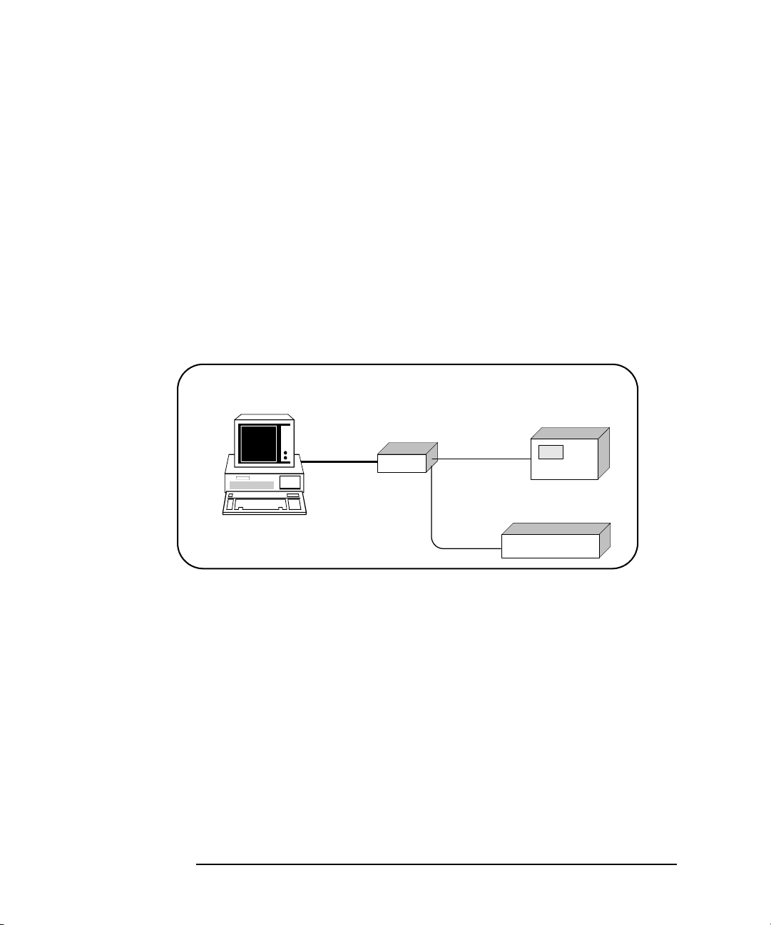
What is a Local Network?
A local (peer-to-peer) network is a network consisting of a computer with an
Ethernet port and an E5810 or a set of networking devices that are
networked together but are not connected to an Enterprise network. The
figure on the next page shows example configurations for Local networks
with hub/switch or crossover cable connections.
In a typical Local network (isolated LAN), a hub or switch may or may not act
as a Dynamic Host Configuration Protocol (DHCP) Server. For Local
Network connections, the E5810 is not visible on the Enterprise network. For
this configuration, multiple PCs can communicate with the E5810 via the hub
or switch.
For direct PC connection to the E5810, a crossover cable is connected from
the E5810 LAN port to a LAN card on the PC. There are no connections to
an Enterprise network. This setup is typically used for local configuration.
For this configuration, only a single PC can communicate with the E5810 via
the crossover cable.
Chapter 2 41
Page 42

Installing the E5810A
Local Network Connections (Multiple PCs can Communicate with the E5810)
LAN GPIB RS232
E5810
Typically Hub
or Switch
GPIB Instruments
To RS-232
Instrument
LAN Patch
Cable
GPIB
GPIB
GPIB
GPIB
LAN GPIB RS232
E5810
GPIB Instruments
To RS-232
Instrument
Crossover
Cable
GPIB
GPIB
GPIB
GPIB
Direct PC Connection (Only One PC can Communicate with the E5810)
Connect to
PC LAN Card
Configuring the E5810A on a Local Network
42 Chapter 2
Page 43

Installing the E5810A
Ethernet Hub/ Switch
1. Connect LAN patch
cables (do NOT use
crossover cables)
4. Connect to AC Power
Typical Local Network Connections (Hub/Switch) (Two PCs)
2. Connect GPIB Cable
to GPIB Instrument(s)
3. Connect RS-232 Cable
to RS-232 Instrument
GPIB
GPIB
Configuring the E5810A on a Local Network
Connecting the E5810A to a Local Network
This section shows how to connect the E5810 to a Local network using an
Ethernet hub/switch or a crossover cable.
E5810 Hub/Switch
Connections
This figure shows typical E5810 Ethernet hub or switch connections. Since
the E5810 has no AC Power switch, the Mains disconnect for the E5810 is
to unplug the AC power cord from the AC outlet.
Chapter 2 43
Page 44

Installing the E5810A
Crossover Cable
User-supplied crossover cable.
Do NOT use LAN "patch" cable.
Crossover cables swap Tx and Rx
lines to enable device communi cation without using a hub/switch.
1. Connect Crossover Cable
4. Connect to AC Power
Typical E5810 Hardware Connections (Crossover Cable)
2. Connect GPIB Cable
to GPIB Instrument(s)
3. Connect RS-232 Cable
to RS-232 Instrument
GPIB
GPIB
GPIB
Configuring the E5810A on a Local Network
E5810 Crossover
Cable Connections
This figure shows typical E5810 connections using a crossover cable. Since
the E5810 has no AC Power switch, the Mains disconnect for the E5810 is
to unplug the AC power cord from the AC outlet. For this configuration, only
one PC can communicate with the E5810.
44 Chapter 2
Page 45

Installing the E5810A
IP Address and Hostname Displayed
Display shows IP address (and Hostname, if known)
Activity
LAN GPIB RS232
Power Fault
Preset
E5810A
LAN/GPIB Gateway
Hostname
169.254.58.10
Configuring the E5810A on a Local Network
Apply Power to the
E5810
After connecting the E5810 to a Local network, plug the E5810 AC power
cord into an AC outlet and observe the power-on sequence. When the
power-on sequence is complete, the default IP address of the E5810 is
displayed on the second line of the front panel display. A typical display
follows. See
Chapter 1, “E5810A Description” for power-on sequences.
NOTE
Local networks may not have a DHCP Server. Since, by default, the
E5810 tries to find a DHCP server until a timeout value is reached, it may
require up to 75 seconds for the E5810 to display its default static IP
address (169.254.58.10).
NOTE
The E5810 detects duplicate IP addresses and will not start operation if
its IP address is already in use. If you try to simultaneously attach multiple
E5810s without changing each unit’s default static IP address, some
E5810s may not start operation.
To prevent this from happening, add a single E5810 at a time to the
network and configure each E5810 to a unique IP address before adding
additional E5810s.
Chapter 2 45
Page 46

Installing the E5810A
Configuring the E5810A on a Local Network
Configuring the E5810A for Local Network Operation
This section gives guidelines to configure the E5810 on a Local network.
This section applies if you plan to configure the E5810 for eventual
installation on a non-DHCP Enterprise network or plan to configure the
E5810 for eventual use on the Local network.
NOTE
When configuring the E5810, we recommend you change the default IP
address to a unique IP address for each E5810 being added to the
system. Otherwise, since the E5810 detects duplicate IP addresses,
some E5810s added to the system may not operate. See Chapter 3,
“Using E5810A Web Access” for details on setting E5810 parameters.
Establishing
Communication
With Your PC
Whether your Local network includes a hub/switch or a crossover cable, the
first step in configuring the E5810 is to establish communication between
your PC and the E5810. To do this, the PC and the E5810 must be on the
same subnet.
One way to put the PC and the E5810 on the same subnet is to use
route add <E5810 IP Address> <PC IP Address> from the
MS-DOS prompt. For example, if IP address of your PC is 155.139.103.152
and the E5810 IP address is 169.254.58.10 (the default), use one of the
following:
! route is lost when the PC is rebooted
route add 169.254.58.10 155.139.103.152
or
! route persists when the PC is rebooted
route -p add 169.254.58.10 155.139.103.152
After communication has been established, you can set any required
configuration parameters for the E5810 by using the E5810 Web access.
46 Chapter 2
Page 47
Installing the E5810A
Configuring the E5810A on a Local Network
Configuring the
E5810 for Enterprise
Network Operation
You can check or set E5810 configuration parameters using the E5810 Web
access that is accessed from your Web browser (Internet Explorer 6.0 or
greater). The steps to set E5810 configuration parameters are:
1 Display the Welcome Page. From your Web browser address line, type
‘http://<E5810 IP Address>’, where <E5810 IP Address> is
the IP address displayed on the E5810 front panel display. Then, press
Enter key to display the E5810 Welcome page.
the
For example, if the default IP address of 169.254.58.10 is displayed on
the E5810 front panel, typing
browser address line and pressing
page. The following figure shows a typical display.
http://169.254.58.10 on your Web
Enter displays the E5810 Welcome
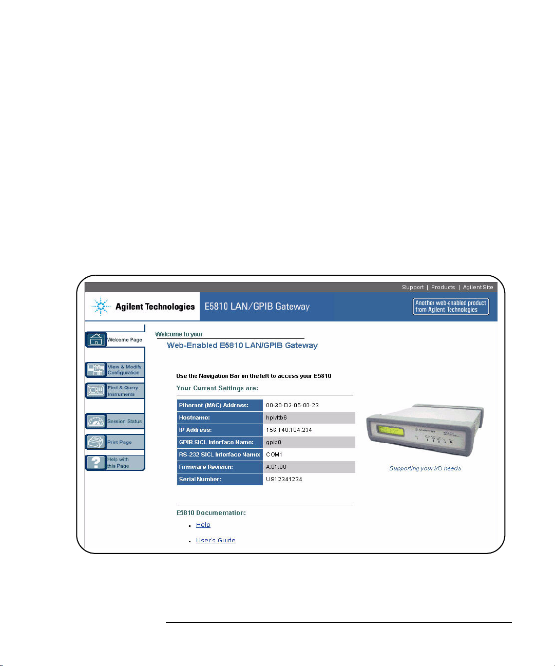
2 Display the Current Configuration Page. From the Welcome page, click
View & Modify Configuration icon to display the Current
the
Configuration of E5810 LAN/GPIB Gateway
Chapter 2 47
page
Page 48

Installing the E5810A
Click this icon
Configuring the E5810A on a Local Network
3 Display the Modify Configuration Page. From the Current Configuration
of E5810 LAN/GPIB Gateway
to display the
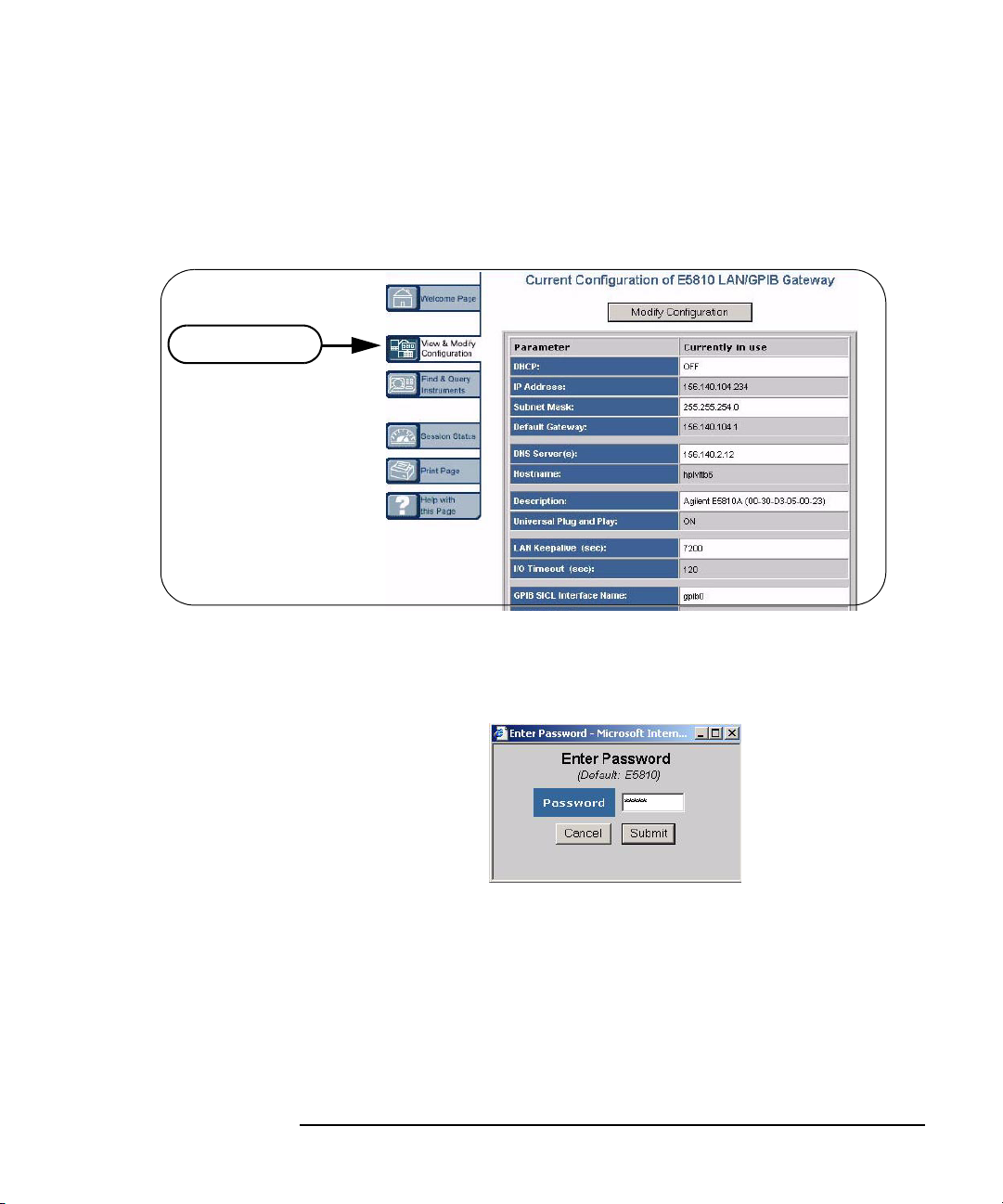
Password dialog box.
page, click the Modify Configuration button
48 Chapter 2
Page 49

Installing the E5810A
Configuring the E5810A on a Local Network
If the default password (E5810) is being used, the password is
displayed as asterisks (*****). If not, type in the current password. Then,
click the
Gateway
Submit button to display the Configuring Your E5810 LAN/GPIB
page.
4 Set E5810 for Enterprise Network Operation. To properly set E5810
configuration parameters for eventual use on an Enterprise network,
you may need to enter the following network values, as provided to you
by your System Administrator, on the
Gateway
page.
Configuring your E5810 LAN/GPIB
Chapter 2 49
Page 50

Installing the E5810A
Configuring the E5810A on a Local Network
IP Address Assignment
Enterprise Network Supports DHCP
No action required. The E5810 automatically
receives an IP address from the network
DHCP Server.
Hostname
Enterprise Network Supports DNS
If the network supports dynamic DNS, enter
the Hostname provided by the System
Administrator. Then, you can access the
E5810 from your Web browser by using the
Hostname.
If the network supports DNS, enter the DNS
Server IP Address provided by the System
Administrator.
Universal Plug and Play (UPnP)
UPnP Enabled is Allowed on Enterprise
Network
Enterprise Network Does Not Support DHCP
Click DHCP OFF and enter the values
provided by the System Administrator for
IP Address, Subnet Mask, and Default
Gateway IP Address.
Enterprise Network Does Not Support DNS
No action required. Hostnames are not
supported. Use only the IP address when
communicating with the E5810.
UPnP Enabled is Not Allowed on Enterprise
Network or You Do Not Want the E5810 to be
Displayed in My Network Places
No action is required for the E5810. However,
if you want to see the E5810 in My Network
Places, you may need to enable UPnP on
your computer’s Operating System.
50 Chapter 2
Set Universal Plug and Play to OFF.
Page 51

Installing the E5810A
1. Set DHCP OFF
Enter New IP Address
Enter New Subnet Mask Value
Enter New Default Gateway IP Address
Leave DNS Server Address Blank
Leave Hostname Blank
Set Universal Plug and Play to OFF.
3. Click Reboot E5810 to reboot
and make changes effective
2. Click the Save button
to save changes
Configuring the E5810A on a Local Network
Example:
Configuring the
E5810
This example shows one way to set various E5810 parameters on the
Configuring your E5810 LAN/GPIB Gateway page, assuming the Enterprise
network to which the E5810 will be connected does not support DHCP or
DNS. Since the network does not support DNS, a Hostname cannot be used
for this E5810. In addition, it is assumed the network does not allow UPnP,
so Universal Plug and Play is set to OFF.
Configuring the
E5810 for Local
Network Operation
If you plan to install your E5810 on a Local network, use the Configuring
your E5810 LAN/GPIB Gateway
Local network.
Where to go Next
To Install the E5810 on an Enterprise Network. Disconnect the E5810
Chapter 2 51
from the Local network and go to “Installing the E5810A on an
Enterprise Network”.
To Use the E5810 on a Local Network. Leave the E5810 connected to
the Local network and go to “Verifying Instrument Communication”.
page to set the parameters applicable to your
Page 52

Installing the E5810A
LAN
Tx
Ln
GP IB
RS232
!
POWER
GPIB
GPIB
GPIB
GPIB Instruments
Typically Hub or
Switch
OR
To Enterprise
Network Instrument
To RS-232
To AC Power
GPIB
LAN
E5810A
Installing the E5810A on an Enterprise Network
Installing the E5810A on an Enterprise
Network
This step gives guidelines to install an E5810 on an Enterprise network.
NOTE
If your Enterprise network does not support Dynamic Host Configuration
Protocol (DHCP), you must first configure your E5810 on a Local network
as shown in “Configuring the E5810A on a Local Network” and then
return to this step to install the E5810 on the Enterprise network.
Connecting the E5810 to the Network
This figure shows typical E5810 connections to an Enterprise network. You
can connect up to 14 GPIB instruments and one RS-232 instrument to each
E5810. Make connections from the E5810 to the network and to GPIB and/
or RS-232 instruments as required
.
52 Chapter 2
Page 53

Installing the E5810A
IP Address and Hostname Displayed
Display shows IP address (and Hostname, if known)
Activity
LAN GPIB RS232
Power Fault
Preset
E5810A
LAN/GPIB Gateway
Hostname
169.254.58.10
Installing the E5810A on an Enterprise Network
After connecting the E5810 to the Enterprise network, plug the E5810 AC
power cord into an AC outlet and observe the power-on sequence. When
the power-on sequence is complete, the assigned IP address of the E5810
is displayed on the second line of the front panel display. A typical display
follows. See Chapter 1, “E5810A Description”
for power-on sequences.
NOTE
The Mains disconnect for the E5810 is to unplug the AC power cord from
the AC outlet. The E5810 has no AC Power switch.
Configuring the E5810A for Enterprise Network Operation
After the E5810 is installed on the Enterprise network, you can check or set
(as required) E5810 configuration parameters using the E5810 Web access
that is accessed from your Web browser (Internet Explorer 6.0 or greater).
The steps to set E5810 configuration parameters are:
1 Display the Welcome Page. To display the E5810 Welcome page, from
your Web browser address line, type
‘http://<E5810 IP Address>’, where <E5810 IP Address> is
the IP address displayed on the E5810 front panel display. Then, press
Enter key.
the
Chapter 2 53
Page 54

Installing the E5810A
Installing the E5810A on an Enterprise Network
For example, if the default IP address of 169.254.58.10 is displayed on
the E5810 front panel, typing http://169.254.58.10 on your Web
browser address line and pressing
Enter displays the E5810 Welcome
page. The following figure shows a typical display.
54 Chapter 2
Page 55
Installing the E5810A
Click this icon
Installing the E5810A on an Enterprise Network
2 Display the Current Configuration Page. from the Welcome page, click
View & Modify Configuration icon to display the Current
the
Configuration of E5810 LAN/GPIB Gateway
page
3 Display the Modify Configuration Page. From the Current Configuration
of E5810 LAN/GPIB Gateway
to display the
Password dialog box.
page, click the Modify Configuration button
If the default password (E5810) is being used, the password is
displayed as asterisks (*****). If not, type in the current password. Then,
click the
Gateway
Submit button to display the Configuring Your E5810 LAN/GPIB
page.
Chapter 2 55
Page 56

Installing the E5810A
Installing the E5810A on an Enterprise Network
56 Chapter 2
Page 57

Hostname
Installing the E5810A
Installing the E5810A on an Enterprise Network
4 Set E5810 for DHCP Enterprise Network Operation. For an Enterprise
network that supports DHCP, the only values you may need to set are
the Hostname and Universal Plug and Play (UPnP) settings, as
provided to you by your System Administrator, on the
E5810 LAN/GPIB Gateway
page.
Configuring your
Enterprise Network Supports DNS
If the network supports dynamic DNS,
enter the Hostname provided by the System
Administrator. Then, you can access the
E5810 from your Web browser by using the
Hostname.
If the network supports DNS, enter the DNS
Server IP Address provided by the System
Administrator.
Universal Plug and Play (UPnP)
UPnP Enabled is Allowed on Enterprise
Network
No action is required for the E5810. However,
if you want to see the E5810 in My Network
Places, you may need to enable
UPnP on your computer’s Operating System.
Where to Go Next
Go to “Verifying Instrument Communication”
Enterprise Network Does Not Support DNS
No action required. Hostnames are not
supported. Use only the IP address when
communicating with the E5810.
UPnP Enabled is Not Allowed on Enterprise
Network or You Do Not Want the E5810 to be
Displayed in My Network Places
Set Universal Plug and Play to OFF.
Chapter 2 57
Page 58

Installing the E5810A
Verifying Instrument Communication
Verifying Instrument Communication
The last step in installing and configuring the E5810 is to verify
communication from your PC to up to 14 connected GPIB instruments and/
or one RS-232 instrument via the E5810 Web access. See
“Using E5810A Web Access”
NOTE
Over the Web, you can interact with instruments via your Web browser.
To program instruments via the E5810 using an application language
such as C or Visual Basic, you must first install and configure the
Agilent IO Libraries Suite as shown in
IO Libraries Suite” on page 61
for details.
“Installing and Configuring Agilent
.
Open the Instrument Page
You can verify instrument communication using the Find and Control
Instruments Connected to your E5810
page of the E5810 Web access.
Chapter 3,
NOTE
Before opening the
page, be sure all connected instruments are plugged in and turned on.
On the address line of your Web browser type
Address>
shown on the front panel display). Then, press
page.
From the
Password dialog box. If the default password is being used, the Password
dialog box shows asterisks (*****). If not, type in the E5810 password. Click
Submit button to display the Find and Control Instruments Connected to
the
your E5810
58 Chapter 2
(where <E5810 IP Address> is the IP address of the E5810
Welcome page, click the Find&Query Instruments icon to display the
page.
Find and Control Instruments Connected to your E5810
http://<E5810 IP
Enter to display the Welcome
Page 59

Installing the E5810A
Verifying Instrument Communication
Instrument Page Functions
From the Find and Control Instruments Connected to your E5810 page, you
can check instrument communication, send command/queries, and do other
functions.
Checking Instrument
Communication
Sending
Commands/Queries
Example: Querying
a DC Voltage Value
To check instrument communication, first select (highlight) the instrument to
be addressed by clicking the SICL Address in the
column. Then, depending on the instrument selected, you can use button
functions (device clear, *IDN?, etc.) to communicate with the instrument.
You can also send instrument-specific commands to applicable instruments
using the Instrument Command line and then clicking
Query. In addition, you can clear the display on the screen by clicking the
Clear History button, set the timeout value (in seconds) by typing in the
desired value in the
operations on instruments connected to the E5810 by clicking the
Pending Operations
For example, the figure on the next page shows one way to identify and
query the DC voltage value of a DMM instrument at SICL address gpib0,22.
See Chapter 3, “Using E5810A Web Access”
Timeout (sec) dialog box, and clear all pending
button.
Instruments Connected
Send, Receive, or
Clear
for details
Chapter 2 59
Page 60

Installing the E5810A
4. Type command on
Instrument Command
line and then click
Query
3. Click the *IDN? button
to identify the instrument
1. Click the Find button (as required)
to display all connected instruments
2. Select Instrument at
SICL Address gpib0,22
Verifying Instrument Communication
Where to Go Next
If you want to program instruments from your PC. Go to
“Installing and Configuring Agilent IO Libraries Suite” on
page 61.
If you do not want to program instruments. This completes
the E5810 installation.
60 Chapter 2
Page 61

Installing the E5810A
Installing and Configuring Agilent IO Libraries Suite
Installing and Configuring Agilent
IO Libraries Suite
NOTE
You must have Administrator privileges to install Agilent IO Libraries Suite
Connection Expert.
This section describes how to install the Agilent IO Libraries Suite on your
PC. The Agilent IO Libraries Suite is a collection of libraries and utilities that
gives you the ability to use your instruments from instrument control
software.
You should install the Agilent IO Libraries Suite as your first step before
installing the hardware because it installs the necessary software and
drivers to control your instruments.
If possible, always use the most recent version of the Agilent IO Libraries
Suite. This version supports the newest interfaces and operating systems,
and has the most advanced features.
1 Verify that your PC meets the minimum system requirements. Refer to
the IO Libraries Web page at www.agilent.com/find/iosuite or the IO
Libraries Suite Readme.
2 Close all applications on your computer. Insert the Agilent
Automation-Ready CD in your CD-ROM drive or download and install
the IO Libraries software from www.agilent.com/find/iosuite.
3 Follow the instructions as prompted during the installation. You can
select either a Typical or a Custom installation:
Typic a l - In most cases, you can select the Typical installation
which installs the IO Libraries Suite using the recommended
settings.
Chapter 2 61
Page 62

Installing the E5810A
Installing and Configuring Agilent IO Libraries Suite
Custom - Select the Custom installation to:
a Install the IO Libraries Suite in another directory
(for 32- bit operating systems only).
b Save disk space by not installing interface manuals.
c Use Agilent 32- bit VISA with another vendor's VISA on
the same PC in side-by-side mode. Details on
side-by-side mode are available at
www.agilent.com/find/side-by-side-install or in the IO
Libraries Suite help.
4 After the IO Libraries suite is successfully installed, you will see the IO
icon on the Windows taskbar notification area.
62 Chapter 2
Page 63

Installing the E5810A
Installing and Configuring Agilent IO Libraries Suite
Configuring a Remote GPIB Interface
This section shows the steps to configure a remote GPIB interface, which
is a logical interface on the client PC that supports communication with GPIB
instruments on your E5810. If you do not have GPIB instruments connected
to your E5810, but do have an RS-232 instrument connected, skip this
section and go to “Configuring a Remote Serial Interface” on page 65.
1 Click the Agilent IO Control icon (IO icon on the Windows taskbar
notification area) and click
Connection Expert utility’s main window.
2 Click Add an interface on the Connection Expert toolbar.
3 In the Manually Add an Interface dialog box, select Remote GPIB
interface
and click Add. The Remote GPIB Interface dialog will appear.
Agilent Connection Expert to display the
4 Specify the TCPIP interface that you wish to use to host this remote
interface, in the
is already configured on your system; by default, a LAN interface
Chapter 2 63
TCPIP interface ID: field. This must be an interface that
Page 64

Installing the E5810A
Installing and Configuring Agilent IO Libraries Suite
named TCPIP0 is configured when you start or refresh Connection
Expert. To change timeouts and protocol properties for your remote
interface, you must change the properties of this TCPIP interface.
5 If your E5810 is on a different subnet from your client PC, type the
hostname or IP address of the E5810 in the
Remote GPIB interface
dialog box. Change the value in the Interface name on remote host: field,
if necessary, to match the
E5810
Welcome page.
GPIB SICL Interface Name displayed on the
If your E5810 is on the same subnet as your client PC, click Find
Interfaces...
Find Now, select your E5810 from the list, and click OK to return to the
Remote GPIB interface dialog box.
. Then, in the Find Remote GPIB Interfaces dialog, click
6 In the Remote GPIB interface dialog box, click Test connection to check
connectivity to your E5810. If the test is successful, you will see the
message
If you leave the check box labeled
to this interface
The interface was successfully opened.
Auto-discover instruments connected
checked, then when you click OK, Connection Expert
will search for GPIB instruments connected to your E5810 and will send
*IDN? (identification) query to each instrument found. You will then
a
see the new remote GPIB interface and any attached GPIB instruments
in the Connection Expert’s explorer view.
64 Chapter 2
Page 65

Installing the E5810A
Installing and Configuring Agilent IO Libraries Suite
Configuring a Remote Serial Interface
This section shows the steps to configure a remote serial interface, which
is a logical interface on the client PC that supports communication with
RS-232 instruments on your E5810. If you do not have an RS-232
instrument connected to your E5810, skip this section and go to the next
step, “Verifying Communication From Your PC” on page 68.
1 Click the Agilent IO Control icon (IO icon on the Windows taskbar
notification area) and click
Connection Expert utility’s main window.
2 Click Add Interface on the Connection Expert toolbar.
3 In the Manually Add an Interface dialog box, select Remote RS-232 serial
interface
appear.
and click Add. The Remote RS-232 Serial Interface dialog will
Agilent Connection Expert to display the
Chapter 2 65
Page 66

Installing the E5810A
Installing and Configuring Agilent IO Libraries Suite
4 Specify the TCPIP interface that you wish to use to host this remote
interface, in the
TCPIP interface ID: field. This must be an interface that
is already configured on your system; by default, a LAN interface
named
TCPIP0 is configured when you start or refresh Connection
Expert. To change timeouts and protocol properties for your remote
interface, you must change the properties of this TCPIP interface.
5 If your E5810 is on a different subnet from your client PC, type the
hostname or IP address of the E5810 in the
Interface
host:
displayed on the E5810
dialog box. Change the value in the Interface name on remote
field, if necessary, to match the RS-232 SICL Interface Name
Welcome page.
Remote RS-232 Serial
If your E5810 is on the same subnet as your client PC, click Find
Interfaces...
Find Now, select your E5810 from the list, and click OK to return to the
Remote RS-232 Serial Interface dialog box.
. Then, in the Find Remote ASRL Interfaces dialog, click
6 In the Remote RS-232 Serial Interface dialog box, click Test connection to
check connectivity to your E5810. If the test is successful, you will see
the message
The interface was successfully opened. Click OK to close
the dialog box. You will see the new remote serial interface in the
Connection Expert’s explorer view.
66 Chapter 2
Page 67

Installing the E5810A
Installing and Configuring Agilent IO Libraries Suite
7 To establish communication with a serial instrument connected to your
E5810, you will need to add this instrument manually in Connection
Expert. (Connection Expert cannot auto-discover serial devices.) In the
main Connection Expert window, click
Instrument
added and click
Auto-identify this instrument checked if your instrument responds to the
*IDN? query, and click OK. The instrument will appear in the Connection
dialog box, select the remote serial interface that you just
OK. In the RS-232 Serial Instrument dialog box, leave
Expert’s explorer view, and if it responds to the
Add Instrument. In the Add
*IDN? query, its
identification information will appear in the properties pane.
Chapter 2 67
Page 68

Installing the E5810A
Installing and Configuring Agilent IO Libraries Suite
Verifying Communication From Your PC
This section gives guidelines to communicate with and to program
connected GPIB and RS-232 instruments from your PC via the E5810,
including:
Using Interactive IO for Communication
Using Supported Programming Languages
NOTE
You can also communicate with (but not program) installed GPIB and/or
RS-232 instruments using the E5810 Web access, whether or not you
have installed and configured the Agilent IO Libraries Suite. See Chapter
3, “Using E5810A Web Access” for details.
Using Interactive IO
for Communication
Example: Using
Interactive IO
After the E5810 has been configured and you have connected your GPIB
and/or RS-232 instruments to the E5810, you can verify communication
between your PC and the instruments by using the Interactive IO utility or by
using VISA or SICL commands with supported programming languages.
This section shows one way to use Interactive IO to verify instrument
communication.
NOTE
Once your remote interface(s) and instrument(s) have been configured in
Connection Expert, if you can see them in the Connection Expert explorer
and see their IDN string information in the detail pane then
communication has been verified. Interactive IO allows you to manually
verify communication and send specific commands to your instrument.
To use Interactive IO to send a *IDN? (identification) query to an instrument:
1 Select the instrument by clicking its icon in the Connection Expert
explorer view.
2 Right-click the instrument and click Send Commands To This Instrument
to display the Interactive IO window. For information on Interactive IO,
including a list of common commands and their meanings, click
Help Topics
.
Help |
68 Chapter 2
Page 69

Installing the E5810A
Installing and Configuring Agilent IO Libraries Suite
3 *IDN? is the default command. Click Send & Read to send the
identification query to the instrument and display its reply in the
Interactive IO window.
4 To send other commands, click Commands> to select from a list of
common commands, or type a command into the
experience timeout errors for some commands, click
the timeout value.
Command: field. If you
Options to change
Applicable
Programming
Documents
Programming Instruments
You can program GPIB and RS-232 instruments via the E5810 using VISA,
VISA COM, or Agilent SICL to send instrument commands such as SCPI.
You can program in various languages/applications, including Visual Studio
.NET languages, Visual Basic, Visual C++, Agilent VEE, and National
Instruments LabVIEW.
For general programming guidelines, see the documentation for your
programming environment. You can also find programming examples using
various I/O libraries and instrument drivers in the instrument
After the E5810 is successfully installed and configured, it should act as a
transparent interface for programming GPIB and RS-232 instruments.
Chapter 2 69
User’s Guide.
Page 70

Installing the E5810A
Installing and Configuring Agilent IO Libraries Suite
For information on programming using Agilent VISA, see the Agilent VISA
User’s Guide
IO Libraries Suite Online Help
programming with the Agilent IO Libraries.
. Also see the Agilent Connectivity Guide and Agilent
for further information and guidelines on
Addressing
Instruments using
VISA and Remote
IO Client
Addressing
Instruments using
VISA and TCPIP
Interface
Once you have created a remote GPIB or remote serial interface in
Connection Expert, you can use ordinary GPIB or serial addressing in your
VISA or VISA COM programs to address instruments on these interfaces.
The Remote IO Client software maps TCPIP address requests into
appropriate interface type (GPIB or ASRL) addresses; thus the IP address
and hostname of the E5810 do not appear in the instrument address. This
makes it possible to use existing programs written for GPIB or ASRL without
having to modify code.
See “Configuring a Remote Serial Interface” on page 65 to configure a
remote GPIB or remote serial interface. VISA programs can then use
addresses such as
RS-232). Use these addresses in your viOpen() call as follows:
viOpen (...”GPIB0::22::INSTR”...)
viOpen (...”ASRL1::INSTR”...)
Although remote GPIB and remote serial interfaces are the most convenient
way to configure and program instruments on your E5810, you may choose
not to use them. For example, if you are using another vendor’s I/O software
rather than the Agilent IO Libraries Suite, your I/O software probably does
not support remote interface addressing. (At the time of this writing, only
Agilent software supports remote interface types.)
If you are not using remote interfaces, you will address your instruments as
TCPIP resources in VISA. These addresses include the IP address or
hostname of the E5810 as well as the SICL address of the device on the
E5810.
GPIB0::22::INSTR (for GPIB) or ASRL1::INSTR (for
Use these addresses in your viOpen() call as follows. These examples
assume that the VISA interface ID of your TCPIP interface is “TCPIP0”. (You
can specify this interface ID with the Connection Expert utility; “TCPIP0” is
the default VISA ID for the default TCPIP interface.)
viOpen (...”TCPIP0::my_IP_address::gpib0,22::INSTR”...)
viOpen (...”TCPIP0::my_IP_address::COM1,488::INSTR”...)
70 Chapter 2
Page 71

Installing the E5810A
Installing and Configuring Agilent IO Libraries Suite
Addressing
Instruments with
SICL
SICL addresses include the IP address or hostname of your E5810 as well
as the SICL address of the device on the E5810, and optionally the protocol
to be used. Some example addresses for SICL programs follow. These
examples assume that the SICL interface ID of your TCPIP interface is “lan”.
(You can specify this interface ID with the Connection Expert utility; “lan” is
the default SICL ID for the default TCPIP0 interface.)
lan[my_IP_Address]:gpib0,22
lan;vxi-11[my_IP_Address]:gpib0,22
lan[my_IP_Address]:COM1,488
lan;sicl-lan[my_IP_Address]:gpib0,11
NOTE
At the time of this writing, National Instruments I/O software does not
support the SICL-LAN protocol, but only the VXI-11 protocol. Because
RS-232 instruments are only supported by SICL-LAN and not VXI-11, you
cannot use National Instruments I/O software to program an RS-232
instrument on your E5810.
Chapter 2 71
Page 72

Notes:
Installing the E5810A
Installing and Configuring Agilent IO Libraries Suite
72 Chapter 2
Page 73

3
Using E5810A Web Access
Page 74

Using E5810A Web Access
This chapter gives guidelines on how to use E5810A Web access, including:
Opening Your Web Browser for E5810A Web Access
Using the Welcome Page
Viewing and Modifying Current Configuration
Finding and Querying Instruments
Other Web Access Functions
74 Chapter 3
Page 75

Using E5810A Web Access
Opening Your Web Browser for E5810A Web Access
Opening Your Web Browser for E5810A Web
Access
Since the E5810 is Web-enabled, you can access and communicate with the
E5810 using your Web browser (Internet Explorer 6.0 or greater).
To display the E5810
http://<E5810 IP Address> or http://<E5810 Hostname>
on the address line, where <E5810 IP Address> is the IP address of the
E5810 and
Then, press the
For example, assume the E5810 IP Address is 169.254.58.10 (the default
static IP address). Typing
displays the E5810
non-default IP address shown) follows. The
page. The banner and the Navigation Bar (Welcome Page, etc.) are a fixed
frame for each page. The text within each page scrolls (as necessary) to
display desired information.
<E5810 hostname> is the Hostname of the E5810 (if known).
Welcome page, open your Web browser and type
Enter key.
http://169.254.58.10 and pressing Enter
Welcome page. A typical Welcome page display (with a
Welcome page is the home
Chapter 3 75
Page 76

Using E5810A Web Access
Navigation
Bar
E5810 Documentation
E5810 Current
Settings
E5810 Support
Information
Using the Welcome Page
Using the Welcome Page
This section shows the features of the E5810 Welcome page, including the
following items. A typical
Navigation Bar
E5810A Current Settings
E5810A Support Information Banner
E5810A Documentation Links
Welcome page display follows.
76 Chapter 3
Page 77

Welcome Page
Displays the Welcome page.
View & Modify Configuration
Displays the
Current Configuration of E5810
LAN/GPIB Gateway
page. From this page, you
can view current E5810 configuration parameters.
Clicking the Modify Configuration button on this
page displays the
Configuring your E5810
LAN/GPIB Gateway page, from which you can
view and modify E5810 configuration.
Session Status
Displays the E5810 LAN/GPIB Gateway Status
page. From this page, you can view the current
Firmware Revision, LAN Speed at Reboot, Time
Since Reboot, and Connection Status.
Print Page
Prints the currently displayed page on your
default printer.
Help with this Page
Displays the Web page help for items on the
currently displayed page.
Find & Query Instruments
First displays the Password
dialog box. After
you enter the E5810 password and click Submit,
the
Find and Control Instruments Connected to
your E5810
page is displayed.
From this page, you can interact with GPIB and
RS-232 instruments connected to the E5810.
Using E5810A Web Access
Using the Welcome Page
Navigation Bar
Clicking the applicable icon on the Navigation Bar on the left side of the page
allows you to take the actions shown in the following figure.
Chapter 3 77
Page 78
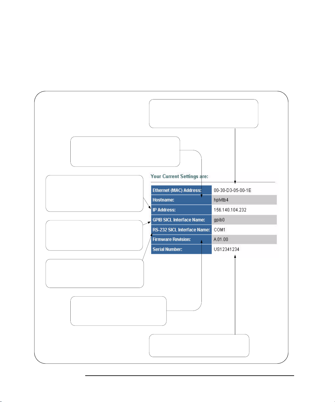
Using E5810A Web Access
Ethernet (MAC) Address
A unique address assigned by the manufacturer
for each Internet device. The Ethernet address
is on a label on the underside of the E5810.
IP Address
The E5810 IP Address. An IP address is a
32-bit numeric address expressed as four
numbers separated by periods (e.g.,
152.160.10.240).
GPIB SICL Interface Name
Each GPIB interface used by Agilent VISA
or SICL must have a SICL Interface Name.
For VXI-11 protocol, use "gpib0".
RS-232 SICL Interface Name
"COM1" is the default value. Client SICL
applications will use full SICL name of
"COM1,488".
Firmware Revision
Current firmware revision on this E5810.
See “Updating E5810 Firmware” for
information on upgrading E5810 firmware.
Hostname
Internet domain name for the E5810 that may
be used to communicate with the E5810. The
Hostname is not a required configuration value.
Serial Number
Unique serial number for this E5810, located
on a label on the underside of the E5810.
Using the Welcome Page
E5810A Current Settings
The Current Settings part of the Welcome page displays some of the current
settings for the E5810. A typical display follows. See “E5810 Configuration
Parameter Descriptions” in this chapter for detailed descriptions.
78 Chapter 3
Page 79

Using E5810A Web Access
Support
Connects you to the Contact Us Web page.
From this page, you can find information about
selecting and purchasing products, technical
support, equipment service and repair, and
training on the Agilent Website.
Products
Connects you to the E5810 Web page.
From this page, you can find product and
service information for the Agilent E5810
on the Agilent Website.
Agilent Site
Connects you to the Agilent Technologies
Web page. From this page, you can access
complete information about Agilent
Technologies from the Agilent Website.
Using the Welcome Page
E5810A Support Information
E5810 support information includes Support, Products, and Agilent Site as
listed on the banner on the top of the page.
NOTE
These links attempt to access the Agilent Web site. Depending on your
network configuration, these links may not be accessible (networkdependent message).
Chapter 3 79
Page 80

Using E5810A Web Access
Help
Clicking
Help displays the contents page of the E5810
help system and allows you to access E5810 help.
This is different than clicking the Help with this Page
icon in that clicking Help provides you with access to
the entire Help system, while clicking the Help with
this Page icon only displays help for the active page.
User's Guide
Clicking User’s Guide displays an electronic (.pdf)
version of this E5810 User’s Guide. This link attempts
to access the Agilent website. Adobe Acrobat
Reader Version 3.0 or later is needed to view the guide.
Using the Welcome Page
E5810A Documentation
You can click Help to access a complete E5810 help system or click User’s
Guide
to display the E5810 LAN/GPIB Gateway for Windows User’s Guide.
80 Chapter 3
Page 81

Using E5810A Web Access
Viewing and Modifying Configuration
Viewing and Modifying Configuration
This section shows how to view and modify (as required) the current
configuration of the E5810 using the
LAN/GPIB Gateway
and the Configuring your E5810 LAN/GPIB Gateway page.
Viewing E5810A Configuration
To begin modifying the E5810 current configuration, click the View & Modify
Configuration
Gateway
icon to display the Current Configuration of E5810 LAN/GPIB
page. A typical display of the page follows.
Current Configuration of E5810
Chapter 3 81
Page 82

Using E5810A Web Access
Viewing and Modifying Configuration
Modifying E5810A Configuration
To modify the current E5810 configuration, from the Current Configuration of
E5810 LAN/GPIB Gateway
top or the bottom of the page to display the
page, click the Modify Configuration button at the
Password dialog box.
Displaying the
Configuration Page
If the default password (E5810) is set as the current password, asterisks
(*****) appear in the window. In this case, just click the
display the
Configuring your E5810 LAN/GPIB Gateway page (see the figure
Submit button to
on the next page). If no asterisks appear, enter the current E5810 password
and then click the
Submit button.
NOTE
If you do not know the current E5810 password, you can temporarily
reset the password to the default (E5810) by pressing the
Preset button
on the front panel of the E5810.
When the
Configuring your E5810 LAN/GPIB Gateway page is displayed, you
can configure desired parameters by typing or selecting the new value in the
Edit Configuration column and then clicking the Save button and then the
Reboot E5810 button at the top or the bottom of the page. See the figure on
the next page for a typical display.
Although there are a few exceptions, most changes to configuration
parameters are not effective until the
Reboot E5810 button is clicked.
Save button is clicked and then the
82 Chapter 3
Page 83

Using E5810A Web Access
Viewing and Modifying Configuration
Chapter 3 83
Page 84

Using E5810A Web Access
Viewing and Modifying Configuration
E5810 Configuration
Parameter
Descriptions
Parameter
[Default]
Default Gateway
[0.0.0.0]
Description
[Factory-Set]
An alphabetical listing of E5810 configuration parameter descriptions and
applicable default (factory-set) values follows. The E5810 uses the default
configuration values until you change any value and save/reboot. The
E5810 also uses the default values when you press and hold down the
Preset button for >10 seconds.
Description
This value is the IP address of the default subnet gateway that allows the
E5810 to communicate with systems that are not on the local subnet.
This is the default subnet gateway where packets are sent which are
destined for a device not on the local subnet, as determined by the
subnet mask setting. Only one default subnet gateway can be configured.
A value of
0.0.0.0 indicates that no subnetting is to be done.
The default description consists of “E5810 LAN/GPIB Gateway” followed
by the Ethernet (MAC) address. The Ethernet address is printed on a
label on the underside of the E5810.
A typical description is:
00-30-D3-05-00-23 is the Ethernet address. The description is the “UPnP
Agilent E5810 00-30-D3-05-00-23, where
Friendly Name” of the E5810 that will automatically be displayed on
UPnP (Universal Plug and Play) enabled LAN hosts.
Domain Name
Server (DNS)
[0.0.0.0]
When the E5810 is connected to the LAN, it broadcasts its presence to
the network if UPnP is enabled. UPnP clients will then see this E5810 in
My Network Places, listed by this Description. A Friendly Name can be up
to 39 characters, including spaces.
A DNS Server is an Internet service that translates domain names into IP
addresses and vice-versa. Every time you use a domain name, a DNS
Server must translate the name into the corresponding IP address.
For example, the domain name
198.105.232.4. The DNS system has its own network. If one DNS Server
www.example.com might translate to
does not know how to translate a particular domain name, it asks another
DNS Server, etc. until the correct IP address is returned, if available.
84 Chapter 3
Page 85

Using E5810A Web Access
Viewing and Modifying Configuration
Parameter
[Default]
Domain Name
Server (DNS)
(cont)
[0.0.0.0]
Description
A DNS Server is an Internet service that translates domain names into IP
addresses. Every time you use a domain name, a DNS server must
translate the name into the corresponding IP address. For example, the
domain name
www.example.com might translate to 198.105.232.4.
The DNS system is distributed. If one DNS server does not know how to
translate a particular domain name, it asks another DNS server, etc. until
the correct IP address is returned. If DHCP is used, a DHCP Server may
provide a DNS Server IP address to the E5810 (this is transparent to the
user). If the user configures a DNS Server, the E5810 will try to use that
Server first.
This parameter shows the IP address of the domain name Server. More
than one address may be listed on the
LAN/GPIB Gateway
page. Up to two of these values may have been
Current Configuration of the E5810
returned by the DHCP Server during startup. Only one static value can be
input on the
Configuring your E5810 LAN/GPIB Gateway page.
The DNS Server provides a Hostname, given an IP Address, for a LAN
device based on entries in its DNS lookup table. If DHCP is OFF and you
do not specify a DNS Server or if Dynamic DNS is not available on your
enterprise LAN and your IP Address is not in the DNS lookup table on the
DNS Server, your Hostname will be unknown and you must address the
E5810 only by its IP Address. The Hostname is not a required entry.
Dynamic Host
Configuration
Protocol (DHCP)
[ON]
DHCP is a protocol for assigning dynamic IP addresses to devices on a
network. DHCP supports a mix of static and dynamic IP addresses. The
two options for DHCP are ON (default) or OFF.
DHCP ON (Default): If DHCP is ON (the factory default setting), the E5810
will try to obtain an IP address from a DHCP Server. If this fails, the
E5810 will use its static IP address. If DHCP is ON and a DHCP Server is
found, the manually configured IP Address, Subnet Mask, and Default
Gateway parameters are not used by the E5810 during startup and thus
are not required settings.
Chapter 3 85
Page 86

Using E5810A Web Access
Viewing and Modifying Configuration
Parameter
[Default]
Dynamic Host
Configuration
Protocol (DHCP)
[ON]
(cont’d)
E5810 Serial
Number
[Factory-Set]
Ethernet (MAC)
Address
[Factory-Set]
GPIB Address
[21]
Description
DHCP OFF:
use the static IP address that may be input in the
LAN/GPIB Gateway
Subnet Mask, and Default Gateway shown in the Configured Value column
If DHCP is OFF or unavailable, during startup the E5810 will
Configuring your E5810
page. In this case, the values for the IP Address,
of the page will be used during startup.
The individual Serial Number assigned at the factory for each E5810. The
Serial Number is printed on a label on the underside of the E5810 and
has the form US12345678.
This is the Media Access Control Address, also known as the link-level
address, the Ethernet (station) Address, the LANIC ID and Hardware
Address. This is a unique 48-bit address assigned by the manufacturer
for each Ethernet device. The address is usually 12 hexadecimal
characters, with colon or dash separators between every two characters,
such as “00:30:D3:05:00:23” or “00-30-D3-05-00-23”. The Ethernet
address is printed on a label on the underside of the E5810.
This value configures the GPIB bus address of the E5810. This address
is used when transfers are made on the GPIB bus. A SICL client
application can change this value by using the SICL function
IGPIBBUSADDR. The GPIB address value can be any number 0 through
30.
GPIB Logical Unit
[7]
GPIB SICL Interface
Name
[gpib0]
This value is the interface logical unit (LU) number of the GPIB interface
in the E5810. It may be used in an Agilent SICL client application’s
iopen
statement to uniquely identify the GPIB interface in the E5810. The GPIB
logical unit value can be any number
1 through 255.
This value is the symbolic name of the GPIB interface in the E5810. It is
used in a SICL client application’s
iopen operation to symbolically
reference the GPIB interface in the E5810. The maximum length of the
GPIB interface name is 15 characters. If VXI-11 (TCP/IP Instrument
Protocol) is used, the name must be
hpib7” may be used to more easily support legacy programs, if only
“
gpib<n>. The names “hpib” or
SICL/LAN protocols will be used.
86 Chapter 3
Page 87

Using E5810A Web Access
Viewing and Modifying Configuration
Parameter
[Default]
Hostname
[None]
I/O Timeout
[120 sec]
Description
This value configures the internet domain name for the E5810.
Hostnames are useful when IP addresses are being assigned by a DHCP
Server, since the Hostname will not change despite DHCP Server
changes and device IP address changes.
If a Hostname is entered, the E5810 will try to register this name when it
boots. The E5810 can only register the Hostname if the network has
Dynamic DNS. If the network does not have Dynamic DNS, this value is
not used. Since you can always use the IP Address or the name (possibly
supplied by another name Server), the Hostname is not a required
configuration value.
You may enter up to 35 characters for the Hostname. The Hostname
must start with a letter and consists of upper and lower case letters and
digits and dashes. There is no default Hostname. If a Hostname is
displayed on the
Welcome page, it is a valid Hostname, since one was
found on the network through DNS.
This value sets the Server I/O timeout in seconds. It configures the E5810
to use an I/O timeout of the specified amount of seconds if the client
requests a timeout of infinity. If
0 is specified for this value and the client
requests an infinite timeout, the E5810 will use a timeout of infinity as
requested.
Setting the I/O timeout to 0 is NOT recommended, as this can result in the
E5810 waiting indefinitely for an I/O operation and effectively “hang” the
E5810.
This timeout value may be used to ensure that the E5810 does not wait
indefinitely for an I/O operation. It also allows the E5810 to detect certain
network events (such as when a client connection is dropped) that may
otherwise go undetected. If the E5810 detects such a condition, it will
release any resources, such as locks, associated with the client.
This value also allows the E5810 to detect certain network events, such
as when a client connection is dropped. If the E5810 detects such a
condition, it will release any resources, such as locks, associated with the
client. The factory default setting is 120 sec.
Chapter 3 87
Page 88

Using E5810A Web Access
Viewing and Modifying Configuration
Parameter
[Default]
IP Address
[169.254.58.10]
LAN Keepalive
[7200 sec]
Description
This value is the Internet Protocol (IP) address of the E5810. The IP
address is a required value and is used for all IP and TCP/IP
communications with the E5810. The IP address is represented in dotted
decimal notation (for example,
154.140.222.201). This number is assigned
by the System Administrator. The E5810 has a default static IP address
169.254.58.10.
of
LAN traffic to the E5810 will be routed by the IP Address or by using a
Hostname that may be provided by a DNS name Server which is mapped
to this IP Address. The current E5810 IP Address may have been
established in one of two ways:
The IP address was provided by a DHCP Server during startup
(dynamic IP address).
The IP address shown on the Current Configuration of the E5810
LAN/GPIB Gateway
169.254.58.10. If DHCP will not be used, the IP address should be
set for your network.
This value sets the LAN connect timeout in seconds. The E5810 may use
the TCP keepalive timer of the TCP/IP protocol stack to determine if a
client is still reachable. By specifying this configuration value, the E5810
turns on the keepalive timer when connecting to the client.
page was used. This was set at the factory to
After the specified time, if there has been no activity on the connection,
the E5810 sends keepalive probes to the client to determine if it is still
alive. After a specified amount of time, the connection will be marked as
down (“dropped”), and the E5810 will release any resources which were
allocated to the associated client.
A value of
0 means no timeout is set. Thus, the E5810 will wait forever
and no keepalive probes are sent. If this value is set, it is recommended
that the largest value be used which still meets the application’s need for
unreachable client detection.
Smaller LAN Keepalive values will generate more keepalive probes
(network traffic), using more of the available network bandwidth.
Allowable values are 0 and greater than or equal to 600 seconds (10
min). The factory default setting is 7200 sec (2 hrs).
88 Chapter 3
Page 89

Using E5810A Web Access
Viewing and Modifying Configuration
Parameter
[Default]
Password
[E5810]
RS-232 Baud Rate
[9600]
Description
E5810 configuration and instrument control pages are passwordprotected against changes. To change from the default password (or any
password) to a new one, enter the current (old) password in the
Configured Value column and enter the new password in both boxes in
Edit Configuration column of the Configuring your E5810 LAN/GPIB
the
Gateway
page. The default password is “E5810”.
You do not need to use a password for SICL or VISA programs with the
E5810 interface. This administrative password is not for security
purposes and will not prevent unauthorized personnel from using the
E5810. The password will only prevent inadvertent changes to the E5810
interface settings or control of instruments attached to the E5810. It is not
intended to provide a strong level of security for either the interface or the
attached network.
Number of bits per second that are transmitted. Available baud rates for
the E5810 are 300, 1200, 2400, 4800, 9600, 19200, 38400, 57600, and
115200. The RS-232 baud rate is the speed of data transmission and
reception on the RS-232 interface. The baud rate value is dependent on
the peripheral device you connect to the RS-232 port. Check the
documentation for your peripheral device to set this value.
RS-232 Bits
[8]
RS-232 Flow
Control
[NONE]
The number of bits that comprise a byte of data. Available number of bits
options are 5, 6, 7, or 8. This is the number of data bits in a character
frame in RS-232 serial data transmission. The value is dependent on the
peripheral device you connect to the RS-232 port. Check the
documentation for your peripheral device to set this value. Available
number of bits options for the E5810 are 5, 6, 7, or 8.
Flow control is the protocol used to pace data transmission over the
RS-232 serial connection. The flow control value is dependent on the
peripheral device you connect to the RS-232 port. Check the
documentation for your peripheral device to set this value. Available flow
control mechanisms for the E5810 are NONE, XON/XOFF, RTS/CTS,
and DTR/DSR.
Chapter 3 89
Page 90

Using E5810A Web Access
Viewing and Modifying Configuration
Parameter
[Default]
RS-232 Parity
[NONE]
RS-232 SICL
Interface Name
[COM1]
RS-232 SRQ
[RI]
Description
Parity is used by the RS-232 hardware to verify data transmission. The
Parity value is dependent on the peripheral device you connect to the
RS-232 port. Check the documentation for your peripheral device to set
this value. Available parity check options for the E5810 are NONE, ODD,
EVEN, SPACE and MARK.
This parameter is the symbolic name of the RS-232 Interface in the
E5810. It is used in an Agilent SICL
iopen operation to symbolically
reference the RS-232 interface in the E5810. It is also used in the
Remote RS-232 Serial Interface dialog (as
Interface name on remote Host)
when specifying an RS-232 device for Agilent VISA.
The RS-232 interface used by Agilent VISA or SICL must have a SICL
Interface Name. The maximum length of the RS-232 SICL Interface
Name is 15 characters.
Method used to request service from the RS-232 device. The SRQ Line is
the modem status line on the RS-232 interface that is monitored for
Service ReQuests (SRQs). Available SRQ options for the E5810 are RI,
DCD, DSR, and CTS.
RS-232 Stop Bits
[1]
Subnet Mask
[255.255.0.0]
A bit that indicates that a byte has just been transmitted. Every byte of
data is preceded by a start bit and followed by a stop bit. Available stop
bit options are 1 or 2. Stop Bits is the number of bits used to indicate the
end of a character frame in RS-232 serial data transmission.
The Stop Bits value is dependent on the peripheral device you connect to
the RS-232 port. Check the documentation for your peripheral device to
set this value. Available stop bit options for the E5810 are 1 or 2.
This value is used to enable the E5810 to determine if a client IP address
is on the same local subnet as the E5810. When a client IP address is on
a different subnet, all packets must be sent to a subnet gateway.
See the
Glossary for an example of a subnet.
90 Chapter 3
Page 91

Using E5810A Web Access
Viewing and Modifying Configuration
Parameter
[Default]
Universal Plug &
Play (UPnP)
[ON]
Description
If Universal Plug & Play (UPnP) is enabled, a multicast message is
generated and sent about once an hour to the subnet. Enterprise
(corporate) networks will want to decide whether this additional traffic is
acceptable. By default, UPnP is NOT enabled on Windows XP. Check
your Operating System instructions to enable UPnP. Universal Plug and
Play (UPnP) has two options: ON or OFF.
Option ON: The E5810 is configured as a UPnP device and
provides information to the network about itself via an XML
description when mounted to the network.
Option OFF: The E5810 is not UPnP capable and will not announce
its presence as a UPnP device when mounted to the network.
Chapter 3 91
Page 92

Using E5810A Web Access
Click Device Clear, *IDN?,
Read STB, or SYST:ERR?
Set instrument timeout
value in secon ds
Clear the
history display
Highlight to select
an instrument
Click the Find button to display
connected instruments. The first
time this page is opened, no
instruments are displayed.
Enter command on
Instrument Comm and line
and then click Send,
Receive, or Query
(sends and receives)
Clear all pending operations
and expire all existing timeouts
on instruments connected to
the E5810.
History
Display
Finding and Querying Instruments
Finding and Querying Instruments
This section shows how to find and query GPIB and/or RS-232 instruments
connected to your E5810 by using the
Connected to your E5810
page. This page is password-protected since you
can inadvertently interfere with running VISA/SICL applications if you query
an instrument at an inappropriate time.
This page allows you to quickly communicate with your GPIB and RS-232
instruments and can help you determine if the instrument side of the E5810
is working properly. You can also use this page to set up and take
measurements remotely by sending instrument commands.
Find and Control Instruments
92 Chapter 3
Page 93

Using E5810A Web Access
Finding and Querying Instruments
Finding Instruments
The Instruments Connected column of the page shows the GPIB and/or
RS-232 instruments connected to your E5810. This column shows the SICL
address for each instrument connected. The SICL address is required for
programmatically interacting with instruments via the E5810.
Using the Find
Button
Checking for
Connected
Instruments
To refresh the display or if instruments have been added/deleted, click the
Find button to display the current configuration. The Find command is
automatically run when the
E5810
page is opened and the correct password is provided. However, when
this page first opens, no instruments are displayed. Click the
display a current list of instruments that are powered up and connected to
the E5810.
After clicking the
below the button. In addition, the top item ("
whether or not you have a RS-232 instrument connected. All other devices
shown in the
GPIB instruments. If no GPIB instruments are found, a message to this
effect is displayed in the output text (History) area.
After using the Find button, if you do not see one or more of your connected
GPIB instruments in the list, try these steps:
1 Check Cables. Make sure all GPIB instruments are connected via GPIB
cables to the E5810 GPIB port and the RS-232 instrument is connected
via an RS-232 cable to the E5810 RS-232 port.
2 Turn Instrument Power ON. Make sure power is turned on for all
instruments. Then, click the
Connected
Find button, all GPIB equipment should appear in the box
Instruments Connected list box are the SICL addresses of your
column.
Find and Control Instruments Connected to your
Find button to
COM1,488") will always be listed
Find button at the bottom of the Instruments
3 Check Hardware. A broken GPIB instrument may short out the GPIB
cable and cause all instruments to show a failure. If you are
experiencing problems, try connecting only one GPIB instrument to the
E5810 at a time. Possible causes of the problem may be broken cable,
loose connectors, two or more instruments at the same GPIB address,
an instrument may be broken, or the E5810 may be broken.
4 Reboot the E5810. After checking hardware connections, reboot the
E5810 to do a self-test of E5810 hardware.
Chapter 3 93
Page 94

Using E5810A Web Access
Finding and Querying Instruments
Querying Instruments
After you have successfully found all connected instruments, you can use
Control Panel for Selected Instrument column of the page to interact with
the
the instruments. There are two ways to interact with connected instruments:
use the buttons at the top of the column or use the
at the bottom of the column.
NOTE
To program instruments using VISA, VISA COM, SICL, or Agilent VEE,
you must install and configure the Agilent IO Libraries Suite on your PC
(see Chapter 2 - Installing the E5810).
For VISA programming information, see the Agilent VISA User’s Guide. If
the Agilent IO Libraries Suite is installed, you can access an electronic
version of the manual by clicking the blue IO icon on the taskbar and then
clicking
menu also includes VISA COM and SICL information.
Documentation | VISA Users Guide. The same Documentation
Instrument Command line
Querying
Instruments Using
the Buttons
After highlighting the instrument to be addressed in the Instruments
Connected
actions for the device.
column, you can click the applicable button to perform these
Return the ID String for IEEE-488.2 compliant devices (*IDN?)
Clear the device (Device Clear)
Read the Status Byte for IEEE-488.2 compliant devices (Read STB)
Return a System Error for SCPI compliant devices (SYST:ERR?)
NOTE
These buttons will work only if the selected instrument supports
IEEE 488.2 and/or SCPI command sets.
In addition, you can clear the display on the screen by clicking the
History
value in the
instruments connected to the E5810 by clicking the
Operations
buttons and the
94 Chapter 3
button, set the timeout value (in seconds) by typing in the desired
Timeout (sec) dialog box, or clear all pending operations on
Clear ALL Pending
button. The following table describes the actions of the six
Timeout (sec) dialog box.
Clear
Page 95

Button Description
Using E5810A Web Access
Finding and Querying Instruments
*IDN?
Device Clear
Read STB
SYST:ERR?
Clear History
Clear ALL
Pending
Operations
Timeout
ID String.
Returns the ID string for the selected IEEE-488.2 compliant
instrument.
Device Clear.
impeded. This can occur for a wide variety of reasons. Sending a
Clear
to the instrument usually solves this problem and restores proper
Sometimes communication with an instrument may be
Device
communication with the instrument. If you encounter an error while doing a
Formatted I/O operation, you can send a
Device Clear to ensure proper
instrument communication is restored.
Read Status Byte.
Returns the decimal and hexadecimal value of the
IEEE-488.2 compliant instrument's Status Byte. Many instruments that
support Formatted I/O also have the ability to read the Status Byte. This
returns information on the status of the instrument, such as error status
and/or busy status. See your instrument manuals for status byte codes.
System Error.
Returns a SCPI system error for a SCPI compliant
instrument. A “0 No errors” return is sent to show no system errors.
Clear the Display
Clear All Pending Operations.
. Clears the (History) display of all previous queries.
Clears all pending operations on instruments
connected to the E5810. This operation expires all existing timeouts on all
devices connected to the E5810. Taking this action may affect other users
currently using the E5810. A password dialog box will appear that asks you
if you really want to do this action.
Change instrument Timeout.
A timeout value is used to limit the amount of
time for an I/O operation to complete. The I/O Timeout value, as set on the
Configuring your E5810 LAN/GPIB Gateway page, may not be long enough
for some instrument activities to complete. Setting a longer timeout here
tells the E5810 to wait a longer time for the instrument to finish.
As an alternative, doing a separate
Send and Receive may also work. Also,
if the configuration value is too long, you may force a shorter timeout here
for faster troubleshooting of instrument tests, etc. To set a different timeout,
enter a Timeout value in the
Timeout text box. This value is used for all
commands issued to an instrument from this page. The valid timeout range
is 1 to 60 seconds.
Chapter 3 95
Page 96

Using E5810A Web Access
Finding and Querying Instruments
Querying
Instruments Using
the Instrument
Command Line
Example: Using the
Instruments Page
For supported instruments, you can also query an instrument by first
highlighting the instrument in the Instruments Connected column, typing in a
SCPI command (such as
line, and then clicking
To send a command to the instrument without waiting for a response, click
Send button. Sending a string to the instrument does not return a result.
the
To receive a string from the instrument, click the
send the string and receive a response from the instrument, click the
button.
NOTE
The History display buffers up to 200 lines of information. At 200 lines,
the last lines are overwritten with new information. At this point, you may
want to press the
This figure shows an example history display after taking these steps:
1 Selecting the instrument at SICL address gpib0,22
2 Clicking the *IDN? and Read STB buttons
3 Typing meas:volt:dc? on the Instrument Command Line
4 Clicking the Query button
meas:volt:dc?) on the Instrument Command
Send and Receive, or Query.
Receive button. To both
Query
Clear History button.
96 Chapter 3
Page 97

Using E5810A Web Access
Firmware Rev ision
Displays the current E5810 firmware revision.
See "Updating E5810 Firmware" for steps to
update to the latest firmware version.
LAN Speed at Reboot
Displays the LAN speed at the time the
E5810 was last rebooted.
Time since Reboot
Displays the time since the last reboot of
the E5810.
Connection Status
Displays the current status of all open
sessions for the E5810, including the Client
IP Address, Session Number, Device/
Instrument Operation (READ, etc.), Lock
Status, and Device/Interface name (such
as gpib0, etc.)
When a device is locked, the device name
(such as DEV) appears in the Lock column.
In this case, this device cannot be used by
anyone other than the user who set the lock.
Other Web Access Functions
Other Web Access Functions
This section describes four other E5810A Web Access functions:
Determining Session Status
Using Web Help
Updating E5810A Firmware
Determining Session Status
To open the E5810 LAN/GPIB Gateway Status page, click the Session Status
icon on the Navigation Bar. A typical display follows. Click the
to update the display to the current configuration.
Refresh button
Chapter 3 97
Page 98
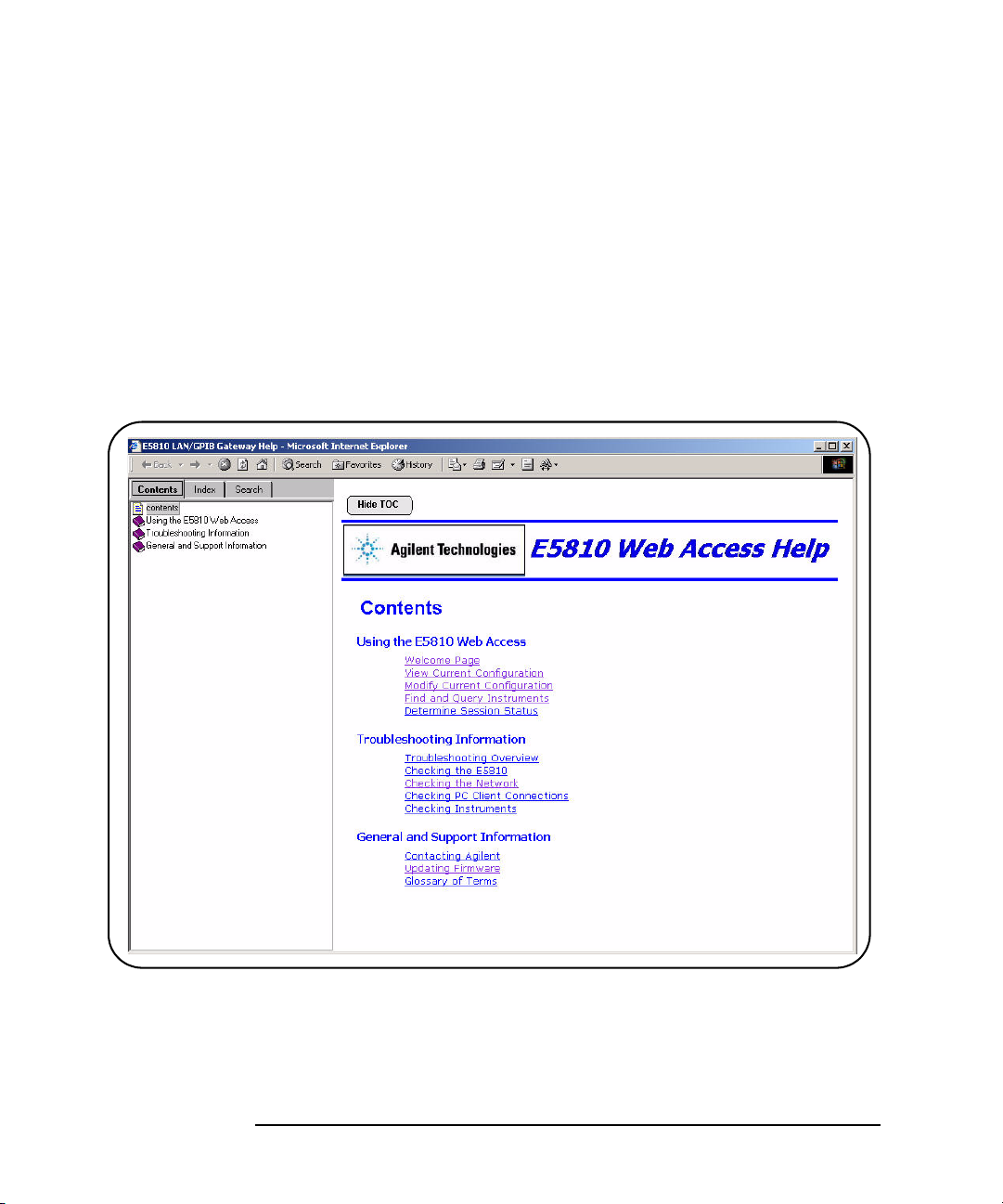
Using E5810A Web Access
Other Web Access Functions
Using Web Help
Clicking Help (under E5810 Documentation) displays the Contents page of
the E5810 Web Access Help system from which you have full access to the
entire help system. The
Note that your specific Windows toolbar appears at the top of the display for
ease of navigation, printing, etc. Also, you can access a topic either from the
Table of Contents on the left side or from the
Click the
Contents is not shown, click the
Contents.
Hide TOC button to hide the Table of Contents. If the Table of
Contents page display follows.
Contents listing on the page.
Show TOC button to display the Table of
98 Chapter 3
Page 99

Using E5810A Web Access
Other Web Access Functions
Updating E5810A Firmware
This section gives guidelines to update your E5810 firmware to the latest
version.
NOTE
Do not update your E5810 firmware unless you have a specific need to
do so, such as defect repair or instrument enhancements. If the firmware
update fails, the E5810 reverts to its original firmware version.
The E5810 uses standard FTP (File Transfer Protocol) to perform updates.
The E5810 acts as an FTP client and searches for an FTP Server that
contains the E5810 firmware image. Agilent maintains a publicly accessible
FTP Server that contains the latest E5810 firmware at:
ftp.agilent.com, login: anonymous, password:
<your e-mail address>
Procedure to
Update E5810
Firmware
The latest E5810 firmware is at /pub/e5810/e5810_latest_firmware.hex
and is called
available in this ftp directory.
If you cannot reach the Agilent FTP Server from your E5810, you can use a
any standard FTP Server that is available, provided you have an image of
the firmware. The requirements are an FTP Server, an image of the E5810
firmware, and a LAN connection between the E5810 and the FTP Server.
The procedure to update E5810 firmware depends on whether or not the
Agilent FTP site is accessible from the E5810. This, in turn, depends on
how your network is configured. The E5810 FTP client used to upload new
firmware is a standard FTP client and currently does not support proxies.
This means that anyone behind a firewall will most likely
directly access the Agilent FTP site.
A description of the two procedures to update E5810 firmware follows.
"e5810_latest_firmware.hex". Prior versions are also
not be able to
If the Agilent FTP site is accessible from the E5810, see “Agilent
FTP Site is Accessible From E5810”
If the Agilent FTP site is not accessible from the E5810, see “Agilent
FTP Site is not Accessible From E5810”
Chapter 3 99
Page 100

Using E5810A Web Access
Other Web Access Functions
Agilent FTP site is
Accessible From
E5810
1 Verify the E5810 is Idle. Updating the E5810 is a significant activity. Be
sure no other user or program is using the E5810 before you attempt to
update the firmware. You can check the number of open sessions by
displaying the
click the
you reboot the E5810 before beginning the firmware update process.
2 Open the Updating Firmware Page
a Open E5810 Web Help and click Updating Firmware in the Table of
Contents to display the
b Click the updating firmware hyperlink on this page to display a
prompt for a password and then display the
your E5810 LAN/GPIB Gateway
display follows.
E5810 LAN/GPIB Gateway Status page. To open this page,
Session Status icon on the Navigation Bar. We also recommend
Updating Your Firmware topic page.
Updating Firmware on
dialog box. A typical dialog box
NOTE
You can also directly access the
GPIB Gateway
where <IP_
panel on the E5810.
3 Check that all Default Parameters are Correct:
page at http://<IP_Address>/html/passwordupdate.html,
Address> is the IP address displayed on the front display
Updating Firmware on your E5810 LAN/
Firmware FTP Server Hostname or IP Address: ftp.agilent.com
User Login: anonymous
Password: ***** (displayed as asterisks)
Firmware Filename: /pub/e5810/e5810_latest_firmware.hex
100 Chapter 3
 Loading...