

Page 1

User’s Guide
Agilent Technologies
E4406A VSA Series
Transmitter Tester
Manufacturing Part Number: E4406-90177
Supersedes E4406-90145
Printed in USA
September 2001
© Copyright 1999 - 2001 Agilent Technologies, Inc.
Page 2

The information contained in this document is subject to change
without notice.
Agilent Technologies makes no warranty of any kind with regard to this
material, including but not limited to, the implied warranties of
merchantability and fitness for a particular purpose. Agilent
Technologies shall not be liable for errors contained herein or for
incidental or consequential damages in connection with the furnishing,
performance, or use of this material.
Safety Information
The following safety notes are used throughout this manual.
Familiarize yourself with these notes before operating this instrument.
WARNING Warning denotes a hazard. It calls attention to a procedure
which, if not correctly performed or adhered to, could result in
injury or loss of life. Do not proceed beyond a warning note
until the indicated conditions are fully understood and met.
CAUTION Caution denotes a hazard. It calls attention to a procedure that, if not
correctly performed or adhered to, could result in damage to or
destruction of the instrument. Do not proceed beyond a caution sign
until the indicated conditions are fully understood and met.
WARNING This is a Safety Class 1 Product (provided with a protective
earth ground incorporated in the power cord). The mains plug
shall be inserted only in a socket outlet provided with a
protected earth contact. Any interruption of the protective
conductor inside or outside of the product is likely to make the
product dangerous. Intentional interruption is prohibited.
WARNING No operator serviceable parts inside. Refer servicing to
qualified personnel. To prevent electrical shock do not remove
covers.
CAUTION Always use the three-prong AC power cord supplied with this product.
Failure to ensure adequate grounding may cause product damage.
2
Page 3

Warranty
This Agilent Technologies instrument product is warranted against
defects in material and workmanship for a period of three years from
date of shipment. During the warranty period, Agilent Technologies
Company will, at its option, either repair or replace products that prove
to be defective.
For warranty service or repair, this product must be returned to a
service facility designated by Agilent Technologies. Buyer shall prepay
shipping charges to Agilent Technologies and Agilent Technologies shall
pay shipping charges to return the product to Buyer. However, Buyer
shall pay all shipping charges, duties, and taxes for products returned
to Agilent Technologies from another country.
Agilent Technologies warrants that its software and firmware
designated by Agilent Technologies for use with an instrument will
execute its programming instructions when properly installed on that
instrument. Agilent Technologies does not warrant that the operation of
the instrument, or software, or firmware will be uninterrupted or
error-free.
LIMITATION OF WARRANTY
The foregoing warranty shall not apply to defects resulting from
improper or inadequate maintenance by Buyer, Buyer-supplied
software or interfacing, unauthorized modification or misuse, operation
outside of the environmental specifications for the product, or improper
site preparation or maintenance.
NO OTHER WARRANTY IS EXPRESSED OR IMPLIED. AGILENT
TECHNOLOGIES SPECIFICALLY DISCLAIMS THE IMPLIED
WARRANTIES OF MERCHANTABILITY AND FITNESS FOR A
PARTICULAR PURPOSE.
EXCLUSIVE REMEDIES
THE REMEDIES PROVIDED HEREIN ARE BUYER’S SOLE AND
EXCLUSIVE REMEDIES. AGILENT TECHNOLOGIES SHALL NOT
BE LIABLE FOR ANY DIRECT, INDIRECT, SPECIAL, INCIDENTAL,
OR CONSEQUENTIAL DAMAGES, WHETHER BASED ON
CONTRACT, TORT, OR ANY OTHER LEGAL THEORY.
3
Page 4

4
Page 5

Contents
1. Getting Started
What Documentation Comes with the E4406A VSA Series Transmitter Tester . . . . . . . . . . 15
URL for the Latest VSA Transmitter Tester Update . . . . . . . . . . . . . . . . . . . . . . . . . . . . . . 17
Understanding Digital Communications Measurements . . . . . . . . . . . . . . . . . . . . . . . . . . . 17
Updating the Firmware . . . . . . . . . . . . . . . . . . . . . . . . . . . . . . . . . . . . . . . . . . . . . . . . . . . . . 18
Making a Measurement . . . . . . . . . . . . . . . . . . . . . . . . . . . . . . . . . . . . . . . . . . . . . . . . . . . . . . . 19
Front Panel Keys Context Dependency. . . . . . . . . . . . . . . . . . . . . . . . . . . . . . . . . . . . . . . . . . . 20
Front Panel Description . . . . . . . . . . . . . . . . . . . . . . . . . . . . . . . . . . . . . . . . . . . . . . . . . . . . . . . 24
Rear Panel Description . . . . . . . . . . . . . . . . . . . . . . . . . . . . . . . . . . . . . . . . . . . . . . . . . . . . . . . 30
Display Annotation . . . . . . . . . . . . . . . . . . . . . . . . . . . . . . . . . . . . . . . . . . . . . . . . . . . . . . . . . . 33
Installing Optional Measurement Personalities . . . . . . . . . . . . . . . . . . . . . . . . . . . . . . . . . . . 36
Available Personality Options . . . . . . . . . . . . . . . . . . . . . . . . . . . . . . . . . . . . . . . . . . . . . . . . 36
Loading the Optional Personality . . . . . . . . . . . . . . . . . . . . . . . . . . . . . . . . . . . . . . . . . . . . . 37
Viewing a License Key . . . . . . . . . . . . . . . . . . . . . . . . . . . . . . . . . . . . . . . . . . . . . . . . . . . . . . 38
Installing a License Key . . . . . . . . . . . . . . . . . . . . . . . . . . . . . . . . . . . . . . . . . . . . . . . . . . . . 39
Using the Uninstall Key . . . . . . . . . . . . . . . . . . . . . . . . . . . . . . . . . . . . . . . . . . . . . . . . . . . . . 39
Cables for Connecting to the Serial Port
(RS-232) . . . . . . . . . . . . . . . . . . . . . . . . . . . . . . . . . . . . . . . . . . . . . . . . . . . . . . . . . . . . . . . . . . . 41
Safety Considerations . . . . . . . . . . . . . . . . . . . . . . . . . . . . . . . . . . . . . . . . . . . . . . . . . . . . . . . . 47
Instrument Installation . . . . . . . . . . . . . . . . . . . . . . . . . . . . . . . . . . . . . . . . . . . . . . . . . . . . . 47
Instrument Operation and Maintenance . . . . . . . . . . . . . . . . . . . . . . . . . . . . . . . . . . . . . . . . 48
2. Using System Features
Using System Keys . . . . . . . . . . . . . . . . . . . . . . . . . . . . . . . . . . . . . . . . . . . . . . . . . . . . . . . . . . 52
Install and Uninstall. . . . . . . . . . . . . . . . . . . . . . . . . . . . . . . . . . . . . . . . . . . . . . . . . . . . . . . . 52
Key Locations . . . . . . . . . . . . . . . . . . . . . . . . . . . . . . . . . . . . . . . . . . . . . . . . . . . . . . . . . . . . . . . 53
Using Print and Print Setup Functions . . . . . . . . . . . . . . . . . . . . . . . . . . . . . . . . . . . . . . . . . . 63
Printing a Displayed Screen . . . . . . . . . . . . . . . . . . . . . . . . . . . . . . . . . . . . . . . . . . . . . . . . . 63
Printing a Screen Image to a File on A: or C: Drives . . . . . . . . . . . . . . . . . . . . . . . . . . . . . . 65
Using File and Save Keys . . . . . . . . . . . . . . . . . . . . . . . . . . . . . . . . . . . . . . . . . . . . . . . . . . . . . 67
Loading a State . . . . . . . . . . . . . . . . . . . . . . . . . . . . . . . . . . . . . . . . . . . . . . . . . . . . . . . . . . . . 67
Saving a State . . . . . . . . . . . . . . . . . . . . . . . . . . . . . . . . . . . . . . . . . . . . . . . . . . . . . . . . . . . . . 67
Using the Alpha Editor Keys . . . . . . . . . . . . . . . . . . . . . . . . . . . . . . . . . . . . . . . . . . . . . . . . . 68
Using Input/Output Configuration Keys . . . . . . . . . . . . . . . . . . . . . . . . . . . . . . . . . . . . . . . . . 69
Configuring I/O . . . . . . . . . . . . . . . . . . . . . . . . . . . . . . . . . . . . . . . . . . . . . . . . . . . . . . . . . . . . 69
File System . . . . . . . . . . . . . . . . . . . . . . . . . . . . . . . . . . . . . . . . . . . . . . . . . . . . . . . . . . . . . . . 71
Reference . . . . . . . . . . . . . . . . . . . . . . . . . . . . . . . . . . . . . . . . . . . . . . . . . . . . . . . . . . . . . . . . . 71
Using System Configuration and Alignment Keys . . . . . . . . . . . . . . . . . . . . . . . . . . . . . . . . . 73
Restore System Defaults. . . . . . . . . . . . . . . . . . . . . . . . . . . . . . . . . . . . . . . . . . . . . . . . . . . . . 73
Show Errors . . . . . . . . . . . . . . . . . . . . . . . . . . . . . . . . . . . . . . . . . . . . . . . . . . . . . . . . . . . . . . 73
Show System . . . . . . . . . . . . . . . . . . . . . . . . . . . . . . . . . . . . . . . . . . . . . . . . . . . . . . . . . . . . . . 74
System (Local) . . . . . . . . . . . . . . . . . . . . . . . . . . . . . . . . . . . . . . . . . . . . . . . . . . . . . . . . . . . . . 76
Alignment . . . . . . . . . . . . . . . . . . . . . . . . . . . . . . . . . . . . . . . . . . . . . . . . . . . . . . . . . . . . . . . . 77
5
Page 6

Contents
3.Setting the Mode
Selecting a Mode . . . . . . . . . . . . . . . . . . . . . . . . . . . . . . . . . . . . . . . . . . . . . . . . . . . . . . . . . . . . .82
Mode Setup . . . . . . . . . . . . . . . . . . . . . . . . . . . . . . . . . . . . . . . . . . . . . . . . . . . . . . . . . . . . . . . . .83
Input Keys . . . . . . . . . . . . . . . . . . . . . . . . . . . . . . . . . . . . . . . . . . . . . . . . . . . . . . . . . . . . . . . .83
Trigger Keys . . . . . . . . . . . . . . . . . . . . . . . . . . . . . . . . . . . . . . . . . . . . . . . . . . . . . . . . . . . . . . .85
Selecting the Frequency/Channel . . . . . . . . . . . . . . . . . . . . . . . . . . . . . . . . . . . . . . . . . . . . . .86
4. Making Measurements
Basic Measurements . . . . . . . . . . . . . . . . . . . . . . . . . . . . . . . . . . . . . . . . . . . . . . . . . . . . . . . . . .88
Preparing for Measurements . . . . . . . . . . . . . . . . . . . . . . . . . . . . . . . . . . . . . . . . . . . . . . . . . . .89
Initial Setup . . . . . . . . . . . . . . . . . . . . . . . . . . . . . . . . . . . . . . . . . . . . . . . . . . . . . . . . . . . . . . .89
Using Measure Keys . . . . . . . . . . . . . . . . . . . . . . . . . . . . . . . . . . . . . . . . . . . . . . . . . . . . . . . .89
Measurement Control . . . . . . . . . . . . . . . . . . . . . . . . . . . . . . . . . . . . . . . . . . . . . . . . . . . . . . .90
Measurement Setup . . . . . . . . . . . . . . . . . . . . . . . . . . . . . . . . . . . . . . . . . . . . . . . . . . . . . . . . .90
Changing the View . . . . . . . . . . . . . . . . . . . . . . . . . . . . . . . . . . . . . . . . . . . . . . . . . . . . . . . . .93
Using Markers . . . . . . . . . . . . . . . . . . . . . . . . . . . . . . . . . . . . . . . . . . . . . . . . . . . . . . . . . . . . .95
Making the Spectrum (Frequency Domain) Measurement. . . . . . . . . . . . . . . . . . . . . . . . . . . .97
Purpose . . . . . . . . . . . . . . . . . . . . . . . . . . . . . . . . . . . . . . . . . . . . . . . . . . . . . . . . . . . . . . . . . .97
Measurement Method . . . . . . . . . . . . . . . . . . . . . . . . . . . . . . . . . . . . . . . . . . . . . . . . . . . . . . .97
Making the Measurement . . . . . . . . . . . . . . . . . . . . . . . . . . . . . . . . . . . . . . . . . . . . . . . . . . . .97
Results . . . . . . . . . . . . . . . . . . . . . . . . . . . . . . . . . . . . . . . . . . . . . . . . . . . . . . . . . . . . . . . . . . .98
Changing the Measurement Setup . . . . . . . . . . . . . . . . . . . . . . . . . . . . . . . . . . . . . . . . . . . . .99
Changing the View . . . . . . . . . . . . . . . . . . . . . . . . . . . . . . . . . . . . . . . . . . . . . . . . . . . . . . . . .103
Changing the Display. . . . . . . . . . . . . . . . . . . . . . . . . . . . . . . . . . . . . . . . . . . . . . . . . . . . . . .105
Using the Markers . . . . . . . . . . . . . . . . . . . . . . . . . . . . . . . . . . . . . . . . . . . . . . . . . . . . . . . . .108
Troubleshooting Hints . . . . . . . . . . . . . . . . . . . . . . . . . . . . . . . . . . . . . . . . . . . . . . . . . . . . . .109
Making the Waveform (Time Domain) Measurement . . . . . . . . . . . . . . . . . . . . . . . . . . . . . . .110
Purpose . . . . . . . . . . . . . . . . . . . . . . . . . . . . . . . . . . . . . . . . . . . . . . . . . . . . . . . . . . . . . . . . .110
Measurement Method . . . . . . . . . . . . . . . . . . . . . . . . . . . . . . . . . . . . . . . . . . . . . . . . . . . . . .110
Making the Measurement . . . . . . . . . . . . . . . . . . . . . . . . . . . . . . . . . . . . . . . . . . . . . . . . . . .110
Results . . . . . . . . . . . . . . . . . . . . . . . . . . . . . . . . . . . . . . . . . . . . . . . . . . . . . . . . . . . . . . . . . .111
Changing the Measurement Setup . . . . . . . . . . . . . . . . . . . . . . . . . . . . . . . . . . . . . . . . . . . .113
Changing the View . . . . . . . . . . . . . . . . . . . . . . . . . . . . . . . . . . . . . . . . . . . . . . . . . . . . . . . . .116
Changing the Display. . . . . . . . . . . . . . . . . . . . . . . . . . . . . . . . . . . . . . . . . . . . . . . . . . . . . . .118
Using the Markers . . . . . . . . . . . . . . . . . . . . . . . . . . . . . . . . . . . . . . . . . . . . . . . . . . . . . . . . .120
Troubleshooting Hints . . . . . . . . . . . . . . . . . . . . . . . . . . . . . . . . . . . . . . . . . . . . . . . . . . . . . .121
Making the Adjacent Channel Power (ACP) Measurement . . . . . . . . . . . . . . . . . . . . . . . . . .122
Purpose . . . . . . . . . . . . . . . . . . . . . . . . . . . . . . . . . . . . . . . . . . . . . . . . . . . . . . . . . . . . . . . . .122
Measurement Method . . . . . . . . . . . . . . . . . . . . . . . . . . . . . . . . . . . . . . . . . . . . . . . . . . . . . .122
Making the Measurement . . . . . . . . . . . . . . . . . . . . . . . . . . . . . . . . . . . . . . . . . . . . . . . . . . .123
Results . . . . . . . . . . . . . . . . . . . . . . . . . . . . . . . . . . . . . . . . . . . . . . . . . . . . . . . . . . . . . . . . . .123
Changing the Measurement Setup . . . . . . . . . . . . . . . . . . . . . . . . . . . . . . . . . . . . . . . . . . . .124
Changing the View . . . . . . . . . . . . . . . . . . . . . . . . . . . . . . . . . . . . . . . . . . . . . . . . . . . . . . . . .128
Troubleshooting Hints . . . . . . . . . . . . . . . . . . . . . . . . . . . . . . . . . . . . . . . . . . . . . . . . . . . . . .130
Making the Channel Power Measurement. . . . . . . . . . . . . . . . . . . . . . . . . . . . . . . . . . . . . . . .131
Purpose . . . . . . . . . . . . . . . . . . . . . . . . . . . . . . . . . . . . . . . . . . . . . . . . . . . . . . . . . . . . . . . . .131
Measurement Method . . . . . . . . . . . . . . . . . . . . . . . . . . . . . . . . . . . . . . . . . . . . . . . . . . . . . .131
Making the Measurement . . . . . . . . . . . . . . . . . . . . . . . . . . . . . . . . . . . . . . . . . . . . . . . . . . .132
Results . . . . . . . . . . . . . . . . . . . . . . . . . . . . . . . . . . . . . . . . . . . . . . . . . . . . . . . . . . . . . . . . . .132
6
Page 7

Contents
Changing the Measurement Setup . . . . . . . . . . . . . . . . . . . . . . . . . . . . . . . . . . . . . . . . . . . 133
Changing the Display . . . . . . . . . . . . . . . . . . . . . . . . . . . . . . . . . . . . . . . . . . . . . . . . . . . . . . 135
Using the Marker . . . . . . . . . . . . . . . . . . . . . . . . . . . . . . . . . . . . . . . . . . . . . . . . . . . . . . . . . 135
Troubleshooting Hints . . . . . . . . . . . . . . . . . . . . . . . . . . . . . . . . . . . . . . . . . . . . . . . . . . . . . 135
Making the Power Stat CCDF Measurement . . . . . . . . . . . . . . . . . . . . . . . . . . . . . . . . . . . . . 136
Purpose . . . . . . . . . . . . . . . . . . . . . . . . . . . . . . . . . . . . . . . . . . . . . . . . . . . . . . . . . . . . . . . . . 136
Measurement Method . . . . . . . . . . . . . . . . . . . . . . . . . . . . . . . . . . . . . . . . . . . . . . . . . . . . . . 136
Making the Measurement . . . . . . . . . . . . . . . . . . . . . . . . . . . . . . . . . . . . . . . . . . . . . . . . . . 137
Results . . . . . . . . . . . . . . . . . . . . . . . . . . . . . . . . . . . . . . . . . . . . . . . . . . . . . . . . . . . . . . . . . . 137
Changing the Measurement Setup . . . . . . . . . . . . . . . . . . . . . . . . . . . . . . . . . . . . . . . . . . . 138
Changing the View . . . . . . . . . . . . . . . . . . . . . . . . . . . . . . . . . . . . . . . . . . . . . . . . . . . . . . . . 139
Changing the Display . . . . . . . . . . . . . . . . . . . . . . . . . . . . . . . . . . . . . . . . . . . . . . . . . . . . . . 139
Using the Markers . . . . . . . . . . . . . . . . . . . . . . . . . . . . . . . . . . . . . . . . . . . . . . . . . . . . . . . . 140
Troubleshooting Hints . . . . . . . . . . . . . . . . . . . . . . . . . . . . . . . . . . . . . . . . . . . . . . . . . . . . . 140
Service Measurements . . . . . . . . . . . . . . . . . . . . . . . . . . . . . . . . . . . . . . . . . . . . . . . . . . . . . . . 141
Timebase Frequency . . . . . . . . . . . . . . . . . . . . . . . . . . . . . . . . . . . . . . . . . . . . . . . . . . . . . . . . 142
Purpose . . . . . . . . . . . . . . . . . . . . . . . . . . . . . . . . . . . . . . . . . . . . . . . . . . . . . . . . . . . . . . . . . 142
Measurement Method . . . . . . . . . . . . . . . . . . . . . . . . . . . . . . . . . . . . . . . . . . . . . . . . . . . . . . 142
Test Setup . . . . . . . . . . . . . . . . . . . . . . . . . . . . . . . . . . . . . . . . . . . . . . . . . . . . . . . . . . . . . . . 142
Results . . . . . . . . . . . . . . . . . . . . . . . . . . . . . . . . . . . . . . . . . . . . . . . . . . . . . . . . . . . . . . . . . . 143
50 MHz Amplitude . . . . . . . . . . . . . . . . . . . . . . . . . . . . . . . . . . . . . . . . . . . . . . . . . . . . . . . . . 144
Purpose . . . . . . . . . . . . . . . . . . . . . . . . . . . . . . . . . . . . . . . . . . . . . . . . . . . . . . . . . . . . . . . . . 144
Measurement Method . . . . . . . . . . . . . . . . . . . . . . . . . . . . . . . . . . . . . . . . . . . . . . . . . . . . . . 144
Test Setup . . . . . . . . . . . . . . . . . . . . . . . . . . . . . . . . . . . . . . . . . . . . . . . . . . . . . . . . . . . . . . . 144
Results . . . . . . . . . . . . . . . . . . . . . . . . . . . . . . . . . . . . . . . . . . . . . . . . . . . . . . . . . . . . . . . . . . 145
Sensors . . . . . . . . . . . . . . . . . . . . . . . . . . . . . . . . . . . . . . . . . . . . . . . . . . . . . . . . . . . . . . . . . . . 146
Purpose . . . . . . . . . . . . . . . . . . . . . . . . . . . . . . . . . . . . . . . . . . . . . . . . . . . . . . . . . . . . . . . . . 146
Measurement Method . . . . . . . . . . . . . . . . . . . . . . . . . . . . . . . . . . . . . . . . . . . . . . . . . . . . . . 146
Test Setup . . . . . . . . . . . . . . . . . . . . . . . . . . . . . . . . . . . . . . . . . . . . . . . . . . . . . . . . . . . . . . . 146
Results . . . . . . . . . . . . . . . . . . . . . . . . . . . . . . . . . . . . . . . . . . . . . . . . . . . . . . . . . . . . . . . . . . 146
Front Panel Test . . . . . . . . . . . . . . . . . . . . . . . . . . . . . . . . . . . . . . . . . . . . . . . . . . . . . . . . . . . 148
Purpose . . . . . . . . . . . . . . . . . . . . . . . . . . . . . . . . . . . . . . . . . . . . . . . . . . . . . . . . . . . . . . . . . 148
Test Setup . . . . . . . . . . . . . . . . . . . . . . . . . . . . . . . . . . . . . . . . . . . . . . . . . . . . . . . . . . . . . . . 148
Results . . . . . . . . . . . . . . . . . . . . . . . . . . . . . . . . . . . . . . . . . . . . . . . . . . . . . . . . . . . . . . . . . . 149
Troubleshooting Hints . . . . . . . . . . . . . . . . . . . . . . . . . . . . . . . . . . . . . . . . . . . . . . . . . . . . . 149
Service Power vs. Time Measurement . . . . . . . . . . . . . . . . . . . . . . . . . . . . . . . . . . . . . . . . . . 150
Purpose . . . . . . . . . . . . . . . . . . . . . . . . . . . . . . . . . . . . . . . . . . . . . . . . . . . . . . . . . . . . . . . . . 150
Using Baseband I/Q Inputs (Option B7C) . . . . . . . . . . . . . . . . . . . . . . . . . . . . . . . . . . . . . . . 151
What are Baseband I/Q Inputs? . . . . . . . . . . . . . . . . . . . . . . . . . . . . . . . . . . . . . . . . . . . . . . 152
What are Baseband I/Q Signals? . . . . . . . . . . . . . . . . . . . . . . . . . . . . . . . . . . . . . . . . . . . . . 153
Why Make Measurements at Baseband?. . . . . . . . . . . . . . . . . . . . . . . . . . . . . . . . . . . . . . . 153
Making Measurements with Baseband I/Q Inputs . . . . . . . . . . . . . . . . . . . . . . . . . . . . . . 154
Baseband I/Q Measurement Overview . . . . . . . . . . . . . . . . . . . . . . . . . . . . . . . . . . . . . . . . 155
Selecting Input Probes for Baseband Measurements . . . . . . . . . . . . . . . . . . . . . . . . . . . . . 156
Selecting Baseband I/Q Inputs . . . . . . . . . . . . . . . . . . . . . . . . . . . . . . . . . . . . . . . . . . . . . . . 159
Selecting Baseband I/Q Input Connectors . . . . . . . . . . . . . . . . . . . . . . . . . . . . . . . . . . . . . . 159
Setting Up Baseband I/Q Inputs . . . . . . . . . . . . . . . . . . . . . . . . . . . . . . . . . . . . . . . . . . . . . 161
Baseband I/Q Measurement Views . . . . . . . . . . . . . . . . . . . . . . . . . . . . . . . . . . . . . . . . . . . 165
Baseband I/Q Measurement Result Examples . . . . . . . . . . . . . . . . . . . . . . . . . . . . . . . . . . 168
7
Page 8

Contents
Baseband I/Q Key Access Locations . . . . . . . . . . . . . . . . . . . . . . . . . . . . . . . . . . . . . . . . . . .172
BbIQ Programming Commands . . . . . . . . . . . . . . . . . . . . . . . . . . . . . . . . . . . . . . . . . . . . . .174
5. If You Have a Problem
Problem Symptoms and Solutions . . . . . . . . . . . . . . . . . . . . . . . . . . . . . . . . . . . . . . . . . . . . . .180
Key or Feature Does Not Appear in Menu . . . . . . . . . . . . . . . . . . . . . . . . . . . . . . . . . . . . . .180
Frequency Unlock or External Reference Missing - Error Messages . . . . . . . . . . . . . . . . .181
LAN External Loopback Test Failed - Error Message . . . . . . . . . . . . . . . . . . . . . . . . . . . . .181
Instrument Fails Alignment - Error Message . . . . . . . . . . . . . . . . . . . . . . . . . . . . . . . . . . .181
Measurement Keys Do Not Appear after Pressing the Mode Key . . . . . . . . . . . . . . . . . . .182
Instrument Power-On Problem . . . . . . . . . . . . . . . . . . . . . . . . . . . . . . . . . . . . . . . . . . . . . . .182
LAN Communication Problem. . . . . . . . . . . . . . . . . . . . . . . . . . . . . . . . . . . . . . . . . . . . . . . .182
Instrument Keyboard is Locked . . . . . . . . . . . . . . . . . . . . . . . . . . . . . . . . . . . . . . . . . . . . . .182
Agilent Technologies Test and Measurement Support, Services, and Assistance . . . . . . . . .183
Returning Your Instrument to Agilent Technologies . . . . . . . . . . . . . . . . . . . . . . . . . . . . . .184
6. Options and Accessories
Options and Measurement Personalities . . . . . . . . . . . . . . . . . . . . . . . . . . . . . . . . . . . . . . . . .186
Option BAH: GSM Measurement Personality . . . . . . . . . . . . . . . . . . . . . . . . . . . . . . . . . . .186
Option BAC: cdmaOne Measurement Personality . . . . . . . . . . . . . . . . . . . . . . . . . . . . . . . .186
Option BAE: NADC/PDC Measurement Personalities . . . . . . . . . . . . . . . . . . . . . . . . . . . .186
Option HN1: iDEN Measurement Personality . . . . . . . . . . . . . . . . . . . . . . . . . . . . . . . . . . .187
Option BAF: W-CDMA Measurement Personality . . . . . . . . . . . . . . . . . . . . . . . . . . . . . . . .187
Option B78: cdma2000 Measurement Personality . . . . . . . . . . . . . . . . . . . . . . . . . . . . . . . .187
Option B7C: Baseband IQ Measurement Personality . . . . . . . . . . . . . . . . . . . . . . . . . . . . .188
Option 202: EDGE (with GSM) Measurement Personality . . . . . . . . . . . . . . . . . . . . . . . . .188
Option 300: 321.4 MHz IF Output . . . . . . . . . . . . . . . . . . . . . . . . . . . . . . . . . . . . . . . . . . . .189
Option 252: Retrofit EDGE to Existing GSM Measurement Personality . . . . . . . . . . . . . .189
Option 0B1: Additional Copy of Manuals . . . . . . . . . . . . . . . . . . . . . . . . . . . . . . . . . . . . . . .189
Option 0BV: Component-level Service Documentation . . . . . . . . . . . . . . . . . . . . . . . . . . . .190
Option 0BW: Assembly-level Service Documentation . . . . . . . . . . . . . . . . . . . . . . . . . . . . .190
Option 1CM: Rack Mount Kit . . . . . . . . . . . . . . . . . . . . . . . . . . . . . . . . . . . . . . . . . . . . . . . .190
Option 1CN: Handles Kit . . . . . . . . . . . . . . . . . . . . . . . . . . . . . . . . . . . . . . . . . . . . . . . . . . . .190
Option 1CP: Rack Mount with Handles Kit . . . . . . . . . . . . . . . . . . . . . . . . . . . . . . . . . . . . .190
Option 1CR: Rack Slide Kit . . . . . . . . . . . . . . . . . . . . . . . . . . . . . . . . . . . . . . . . . . . . . . . . . .190
VSA Transmitter Tester Measurement Personalities Retrofit . . . . . . . . . . . . . . . . . . . . . .190
Accessories . . . . . . . . . . . . . . . . . . . . . . . . . . . . . . . . . . . . . . . . . . . . . . . . . . . . . . . . . . . . . . . . .191
AC Probe . . . . . . . . . . . . . . . . . . . . . . . . . . . . . . . . . . . . . . . . . . . . . . . . . . . . . . . . . . . . . . . .191
Broadband Preamplifiers and Power Amplifiers . . . . . . . . . . . . . . . . . . . . . . . . . . . . . . . . .191
GPIB Cable . . . . . . . . . . . . . . . . . . . . . . . . . . . . . . . . . . . . . . . . . . . . . . . . . . . . . . . . . . . . . .191
Parallel Interface Cable . . . . . . . . . . . . . . . . . . . . . . . . . . . . . . . . . . . . . . . . . . . . . . . . . . . .191
Printer . . . . . . . . . . . . . . . . . . . . . . . . . . . . . . . . . . . . . . . . . . . . . . . . . . . . . . . . . . . . . . . . . .191
RS-232 Cables . . . . . . . . . . . . . . . . . . . . . . . . . . . . . . . . . . . . . . . . . . . . . . . . . . . . . . . . . . . .192
N2714A Calibration and Adjustment Software . . . . . . . . . . . . . . . . . . . . . . . . . . . . . . . . . .192
8
Page 9

List of Keys
Linear Envelope .................................................................................................................................. 166
10 MHz Out............................................................................................................................................72
50 MHz Amplitude...............................................................................................................................144
50 MHz Ref.............................................................................................................................................83
Advanced ................................................................................................................................................ 90
Align 50 MHz Reference ........................................................................................................................ 78
Align ADC .............................................................................................................................................. 78
Align All Now .........................................................................................................................................77
Align Current IF Flatness ..................................................................................................................... 78
Align Current SysGain .......................................................................................................................... 78
Align IF ..................................................................................................................................................78
Align RF ................................................................................................................................................. 78
Align Subsystem ....................................................................................................................................78
Alignments ............................................................................................................................................. 77
Alpha Editor...........................................................................................................................................68
Auto Align .............................................................................................................................................. 77
Auto Trig ................................................................................................................................................ 85
Average................................................................................................................................................... 90
Avg Bursts..............................................................................................................................................91
Avg Mode................................................................................................................................................ 91
Avg Number ........................................................................................................................................... 91
Avg Type................................................................................................................................................. 91
Band Power ............................................................................................................................................ 96
Baseband Align Signal (ON OFF).......................................................................................................160
Basic ....................................................................................................................................................... 82
cdmaOne................................................................................................................................................. 82
Clear Error Queue(s) ............................................................................................................................. 74
Color Print.............................................................................................................................................. 63
Color Printer .......................................................................................................................................... 63
Config I/O ...............................................................................................................................................69
Corrections ............................................................................................................................................. 79
Current ................................................................................................................................................... 93
Custom. ..................................................................................................................................................63
Define Custom........................................................................................................................................63
Delay....................................................................................................................................................... 85
Delta .......................................................................................................................................................96
Eject Page...............................................................................................................................................63
Emulated GPIB Address ....................................................................................................................... 71
Emulated GPIB Logical Unit ................................................................................................................70
Emulated GPIB Name........................................................................................................................... 70
ESC ......................................................................................................................................................... 77
Ethernet Addr ........................................................................................................................................ 71
Ext Front ................................................................................................................................................ 86
Ext Rear ................................................................................................................................................. 86
File Location........................................................................................................................................... 65
Frame Timer .......................................................................................................................................... 86
Frame ..................................................................................................................................................... 92
Free Run.................................................................................................................................................92
Freq Ref ..................................................................................................................................................71
9
Page 10

List of Keys
Front Panel Test...................................................................................................................................148
GPIB Address .........................................................................................................................................69
GSM ........................................................................................................................................................82
HCOPy Dest ...........................................................................................................................................65
Host Name..............................................................................................................................................70
I Offset ..................................................................................................................................................161
I Only ....................................................................................................................................................159
I/Q Input Z............................................................................................................................................162
I/Q INPUT ............................................................................................................................................103
I/Q Range..............................................................................................................................................161
I/Q Setup...............................................................................................................................................161
I/Q Z Ref for Input Z = 1M
IF Align...................................................................................................................................................83
Image ......................................................................................................................................................65
Input Atten .............................................................................................................................................84
Input Port ...............................................................................................................................................83
install ......................................................................................................................................................36
Instrument Logical Unit........................................................................................................................70
Instrument Name...................................................................................................................................70
Invert ......................................................................................................................................................65
IP Address ..............................................................................................................................................70
Landscape...............................................................................................................................................63
Language, ...............................................................................................................................................63
Level........................................................................................................................................................85
License Key ............................................................................................................................................38
Line .........................................................................................................................................................92
Load State ..............................................................................................................................................67
Log-Pwr Avg ...........................................................................................................................................91
Marker All Off ........................................................................................................................................96
Max Total Pwr........................................................................................................................................84
Maximum Connections ..........................................................................................................................70
Maximum................................................................................................................................................91
Minimum ................................................................................................................................................91
Noise .......................................................................................................................................................96
Normal ....................................................................................................................................................95
Offset.......................................................................................................................................................86
Orientation .............................................................................................................................................63
PCL3 .......................................................................................................................................................63
PCL5 .......................................................................................................................................................63
Peak Level ..............................................................................................................................................85
Period......................................................................................................................................................86
Portrait ...................................................................................................................................................63
Pos...........................................................................................................................................................85
Printer ....................................................................................................................................................65
Pwr Avg ..................................................................................................................................................91
Q Offset.................................................................................................................................................162
Q Only...................................................................................................................................................159
Ref Position.............................................................................................................................................94
Ref Value.................................................................................................................................................93
Ω............................................................................................................................ 162
10
Page 11

List of Keys
Reference ................................................................................................................................................71
Reprint.................................................................................................................................................... 63
Res BW ...................................................................................................................................................90
Reset Offset Display .............................................................................................................................. 86
Restore Align Defaults...........................................................................................................................79
Restore Meas Defaults........................................................................................................................... 90
Resume ................................................................................................................................................... 90
RF Burst (Wideband)............................................................................................................................. 85
RF ........................................................................................................................................................... 83
Save State...............................................................................................................................................67
Scale/Coupling ....................................................................................................................................... 94
Scale/Div................................................................................................................................................. 93
SCPI LAN............................................................................................................................................... 70
Select ...................................................................................................................................................... 96
Sensors ................................................................................................................................................. 146
Server ..................................................................................................................................................... 70
Service ....................................................................................................................................................82
Shape ...................................................................................................................................................... 96
Show Errors ........................................................................................................................................... 73
SICL Server............................................................................................................................................ 70
Signal Amptd ......................................................................................................................................... 84
Signal Type ............................................................................................................................................84
Slope ....................................................................................................................................................... 85
Socket Port .............................................................................................................................................70
Span........................................................................................................................................................ 93
Sweep Time ............................................................................................................................................ 93
Sync Source ............................................................................................................................................ 86
Telnet Port .............................................................................................................................................. 70
Time Corr ...............................................................................................................................................79
Timebase Frequency ............................................................................................................................ 142
Trace ....................................................................................................................................................... 95
Trig Holdoff ............................................................................................................................................ 85
Trigger .................................................................................................................................................... 85
Verbose ...................................................................................................................................................74
Video (IF Envlp).....................................................................................................................................85
Visible Align ...........................................................................................................................................79
Voltage Avg............................................................................................................................................. 91
11
Page 12

List of Keys
12
Page 13

1 Getting Started
This chapter introduces you to basic features of the instrument,
including front panel keys, rear panel connections, and display
annotation. You will also find out how to make a basic measurement
and install applications.
13
Page 14

Getting Started
Topics in c l ud e :
“What Documentation Comes with the E4406A VSA Series
Transmitter Tester” on page 15.
“Making a Measurement” on page 19.
“Front Panel Keys Context Dependency” on page 20.
“Front Panel Description” on page 24.
“Rear Panel Description” on page 30.
“Display Annotation” on page 33.
“Installing Optional Measurement Personalities” on page 36.
“Safety Considerations” on page 47.
“Cables for Connecting to the Serial Port (RS-232)” on page 41.
14 Chapter 1
Page 15

Getting Started
What Documentation Comes with the E4406A VSA Series Transmitter Tester
What Documentation Comes with the E4406A
VSA Series Transmitter Tester
With your purchase of the instrument you receive the following
materials:
Table 1-1 Standard Documentation
Part Description Notes
User’s Guide Does not include operational
information on the optional
measurement personalities.
Specifications Includes specifications for the
transmitter tester and all optional
measurement personalities. (Special
options will be documented elsewhere.)
Programmer’s Guide Does not include commands for the
optional measurement personalities
Documentation CD-ROM Includes programming examples. Does
not include service documentation or
software
An E4406A standard instrument contains the Basic and Service modes,
which are described in the User’s Guide.
If you have purchased an optional measurement personality, your
instrument comes loaded with the personality you have selected plus
the Basic and Service modes. You also receive the related guide,
containing measurement and programming information, for the
personality you have ordered.
Chapter 1 15
Page 16

Getting Started
What Documentation Comes with the E4406A VSA Series Transmitter Tester
Table 1-2 Personality Documentation
Measurement Option Part Description
Option BAC cdmaOne Guide
Option BAH GSM Guide
Option 202 EDGE (w/GSM) Guide
Option BAE NADC, PDC Guide
Option BAF W-CDMA Guide
Option B78 cdma2000 Guide
Service documentation is also available from Agilent Technologies.
NOTE If the shipping container is damaged, or any part is missing, notify
Agilent Technologies (see page 184 for locations). When transporting
the instrument use the original or comparable packaging.
16 Chapter 1
Page 17

Getting Started
What Documentation Comes with the E4406A VSA Series Transmitter Tester
URL for the Latest VSA Transmitter Tester Update
For the latest information about this instrument, including firmware
upgrades, application information, and product information, please
visit the following URL: www.agilent.com/find/vsa/.
Understanding Digital Communications Measurements
Additional measurement application information is available through
your local Agilent Technologies sales and service office. See the “If You
Have a Problem” chapter for office location information. Some available
application notes are listed below.
Description
Digital Modulation in Communications Systems An Introduction, Application Note 1298
Understanding CDMA Measurements for Base
Stations and Their Components, Application Note
1311
Understanding GSM Transmitter Measurements,
Application Note 1312
HPSK Spreading for 3G 5968-8438E
Agilent E4406A VSA Series Transmitter Tester
Self-Guided Tour
Designing and Testing 3GPP W-CDMA Base Stations,
Application Note 1355
Designing and Testing 3GPP W-CDMA User Equip-
ment, Application Note 1356
Designing and Testing IS-2000 Base Stations,
Application Note 1357
Agilent Part
Number
5965-7160E
5968-0953E
5968-2320E
5968-7617E
5980-1239E
5980-1238E
5980-1303E
Designing and Testing IS-2000 Mobile Stations,
Application Note 1358
Understanding PDC and NADC Transmitter
Measurements for Base Transceiver Stations and
Mobile Stations, Application Note 1324
Chapter 1 17
5980-1237E
5968-5537E
Page 18

Getting Started
What Documentation Comes with the E4406A VSA Series Transmitter Tester
Updating the Firmware
Updated versions of the E4406A VSA Transmitter Tester firmware will
be available from several sources. Information on the latest firmware
revision can be accessed through the following URL.
URL to Contact to Obtain Firmware Update Information
www.agilent.com/find/vsa/
18 Chapter 1
Page 19

Getting Started
Making a Measurement
Making a Measurement
This instrument enables you to make a wide variety of measurements
on digital communications equipment using the
measurement capabilities. It also has optional measurement
personalites that make measurements based on industry standards.
To set up the instrument to make measurements, you need to:
1. Select a mode or personality which corresponds to a digital
communications format, like cdma2000, W-CDMA, or EDGE. Use
the Basic mode to make measurements of signals with non-standard
formats. After selection of the mode, adjustments to the mode
settings may be made as required.
2. Select a specific measurement to be performed, like ACP, Channel
Power, or EVM, etc. After selection of a measurement, adjustments
to the measurement settings may be made as required.
Basic Mode
Depending on Measurement Control settings, the instrument will
begin making the selected measurements. The resulting data will be
shown on the display or available for export.
3. Select a front panel View to display the data from the current
measurement. Depending on the mode and measurement selected,
various graphical and tabular presentations are available.
If you have a problem, and get an error message, see the E4406A VSA
Transmitter Tester Instrument Messages and Functional Tests Guide.
The main keys used in the three steps are shown in the table below.
Step Primary Key Setup Keys Related Keys
1. Select & setup a
mode
2. Select & setup a
measurement
3. Select & setup a
view
MODE Mode Setup, Input,
FREQUENCY/
Channel
MEASURE Meas Setup Meas Control, Restart
View/Trace SPAN X Scale,
AMPLITUDE Y Scale
Display
, Zoom ,
Next Window
System
File, Save, Print, Print
Setup
,
, Marker, Search
A setting may be reset at any time, and will be in effect on the next
measurement cycle or View.
Chapter 1 19
Page 20
Getting Started
Front Panel Keys Context Dependency
Front Panel Keys Context Dependency
Many of the instrument features are context dependent. The functions
that are available will change based on your selections of mode, mode
setup, measurement, and measurement setup. The following figures
represent the dependency relationships of the front panel keys.
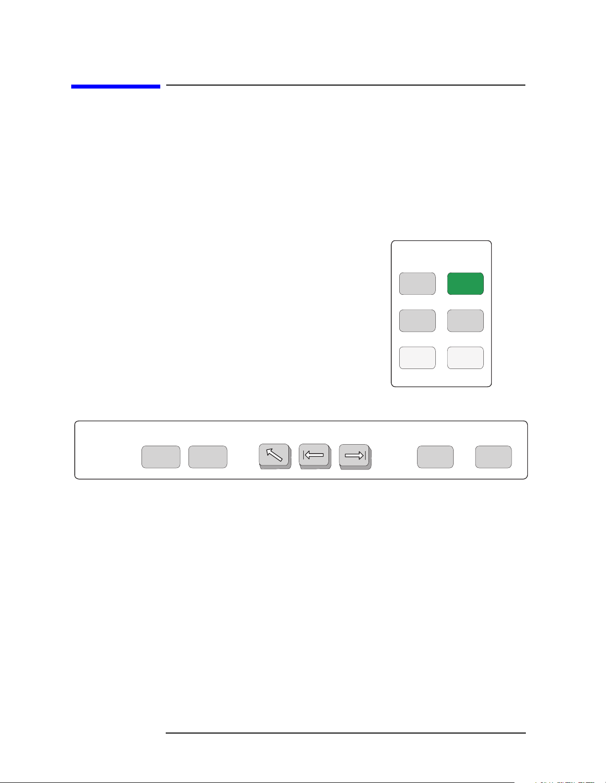
Figure 1-1 System and Navigation Keys are not Context Dependent
System
PresetSystem
Navigation
Next
Window
File
Save
Print
Setup
Print
TabWindow
Zoom Return Esc
20 Chapter 1
Page 21

Getting Started
Front Panel Keys Context Dependency
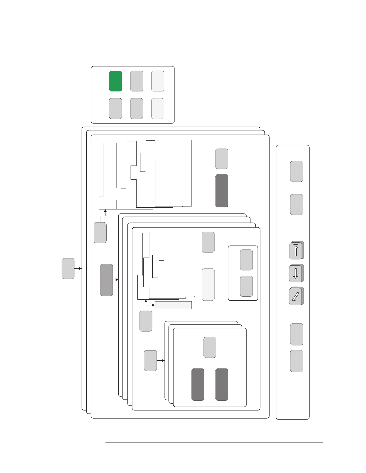
Figure 1-2 These Features are Dependent on the Selected Mode and the
Mode Setup
MODE
Service
GSM
cdmaOne
Channel Power
Statistics View
Spectrum View
I/Q View
Waveform (Time Domain)
Spectrum (Freq Domain)
Spurious Close
View/
Trace
Meas
Setup
M
e
n
u
s
MEASURE
Averaging
Trigger Source
Advanced
Limits
Mode
Setup
Radio
Standard: TIA-95B PCS
Device: MS, BS
Input
Trigger
Demod
RF Chan
Frame
SPAN
X Scale
AMPLITUDE
Y Scale
Display
Restart
Marker
Marker
Search
Meas
Control
FREQUENCY
Channel
Input
Chapter 1 21
Page 22

Getting Started
Front Panel Keys Context Dependency
Figure 1-3 These Features are Dependent on the Selected Measurement
and the Measurement Setup
Waveform (Time Domain)
Spectrum (Freq Domain)
Spurious Close
Channel Power
Statistics View
Spectrum View
I/Q View
SPAN
X Scale
AMPLITUDE
Y Scale
View/
Trace
Display
Meas
Setup
*
M
e
n
u
s
MEASURE
Averaging
Trigger Source
Restart
Marker
*
Advanced
Limits
Meas
Control
Marker
Search
* Some Measure and Meas Setup parameters are context dependent upon the
Radio variant and Device selected in the Mode Setup.
22 Chapter 1
Page 23
Front Panel Keys Context Dependency
Figure 1-4 Front Panel Keys Context Dependent Relationships
Getting Started
System
Device: MS, BS
Standard: TIA-95B PCS
Radio
Mode
Setup
PresetSystem
Trigger
Input
Print
Setup
File
Demod
Frame
RF Chan
Print
Save
Limits
Meas
Control
Input
FREQUENCY
Channel
MODE
Service
GSM
cdmaOne
MEASURE
Waveform (Time Domain)
Spectrum (Freq Domain)
Spurious Close
Channel Power
Advanced
Trigger Source
Averaging
Meas
Setup
View/
Trace
enu
M
Statistics View
Spectrum View
I/Q View
Search
TabWindow
Marker
Restart
s
Display
SPAN
X Scale
AMPLITUDE
Y Scale
Marker
Zoom Return Esc
Next
Window
Navigation
Chapter 1 23
Page 24
Getting Started
Front Panel Description
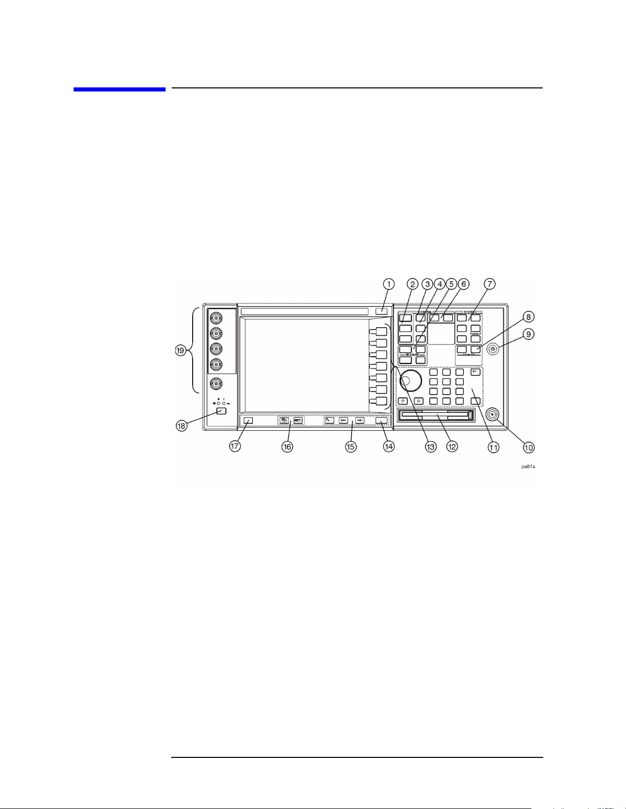
Front Panel Description
Key menus may vary depending on the currently selected mode or
measurement. Softkeys which are not available for use are greyed-out.
Keys may be greyed-out as a result of:
the current setting of other inter-related functions,
not having a required password or license key, or
not having some piece of optional hardware that is required.
Paths to access any feature will be found in the key access table on
page 53. Display annotation is explained on page 33. Operation of the
3.5 inch floppy-drive is covered in the section on printing on page 63.
1. ESC key Use the escape key to exit any function without
modifying current parameters. Pressing the
ESC key
will:
• Clear any numeric entry that you have begun to
enter but decided you want to cancel.
• Remove any entries that are visible in the active
function area of the display (see the section on
annotation on page 33 for a description of the active
function area and other display features).
• Cancels an alignment if one is in progress.
2. Control keys
Sets parameters that are used by the measurement in
the current measurement mode.
24 Chapter 1
Page 25

Getting Started
Front Panel Description
• FREQUENCY/Channel accesses softkeys that control
the center frequency or channel number. These
parameters apply to all measurements in the
current mode.
SPAN/X Scale accesses softkeys that control the
•
horizontal scale in units of frequency, time, symbols
or bits. The parameters in this menu apply only to
the active window in the current measurement. See
page 93 for more detail.
AMPLITUDE/Y Scale accesses softkeys that control
•
vertical scale functions in units of dBm, dB, volts,
degrees, or radians. The parameters in this menu
apply only to the active window in the current
measurement. See page 93 for more detail.
3. Input key The
Input key accesses softkeys that control the input of
the transmitter tester. These affect all measurements
within the current mode. Note that the internal
50 MHz reference signal and the IF align signal are
used as internal inputs that do not require external
connections. See page 73 for more detail.
4. View keys
View keys modify the format of the trace and numeric
data on the display. See page 93 for more detail.
View/Trace accesses softkeys that control the way
•
results are viewed.
Display accesses softkeys that change the display.
•
Functions such as limit mask on/off and dots on/off
are available for some measurements.
5. Measure keys are used to select and set up a specific measurement
within the selected application. See page 89 for more
detail.
MEASURE accesses softkeys that select and initiate
•
the various measurements that are specific to the
current mode.
Meas Setup accesses the setup parameters that are
•
specific to the current measurement.
•
Restart causes the measurement that is currently in
process to stop, then start again at the beginning
according to the current measurement setup
parameters.
Meas Control accesses softkeys that affect the
•
measurement after it has been setup, for example
selecting a single or continuous measurement.
Chapter 1 25
Page 26

Getting Started
Front Panel Description
6. Mode keys select the measurement mode and mode parameters
See page 83 for more detail.
MODE accesses softkeys to select the instrument
•
mode. Each mode is independent of all other modes.
Mode Setup accesses softkeys that affect parameters
•
that are specific to the current mode and affect all
measurements within that mode.
7. System keys access system features, that are used with all
instrument modes. See page 52 for further explanation
of system features.
System accesses features that control instrument
•
configuration at the system level, like I/O
configuration and alignment, which affect all
instrument modes. Pressing
System also returns the
instrument to local control, if it has been in remote
mode.
Preset resets all parameters of the current mode back
•
to the factory defaults.
•
Print immediately prints what is on the screen to the
printer, or saves a file to a floppy disc, according to
the parameters that are currently set in the
menu. See page 63 for more detail.
Setup
Print Setup configures the transmitter tester for
•
Print
printing to a printer, or saving an image file to the
floppy disc drive, and also allows you to select the
printer type.
File accesses softkeys that control the file system of
•
the transmitter tester for saving and loading
instrument states. See page 67 for more detail.
Save saves the current instrument state in the File
•
menu. See page 67 for more detail.
8. Marker keys are used to obtain specific information about parts of
the displayed measurement (for example, to identify
the exact frequency of an offset
). See page 95 for more
detail.
Marker accesses softkeys that allow manual
•
positioning of markers.
•
Search automatically performs a peak search, and
accesses softkeys that automatically position
markers at preset locations on the trace (for
example, to determine the difference between the
amplitude of one peak and another).
26 Chapter 1
Page 27

Getting Started
Front Panel Description
9. Probe Power The probe power input supplies power for external
probes; the three connectors are a ground, and a +15 V,
and a
−12.6 V connector. The probe power supplies
power to high frequency probes and accessories, such as
preamplifiers, that are used as accessories to the
transmitter tester. The probe power provides a
maximum of 150 mA.
10. RF Input The 50
Ω RF input allows for input of an external RF
signal. The connector is a type N female, and is rated
for a maximum input of +35 dBm for measuring a CW
signal, and a maximum of 26 volts for a DC signal.
11. Data Entry keys are used to enter numeric values. Entries made
using data entry keys will be visible in the active
function area (see the section on annotation on page 33
to locate the active function area).
• The
Enter key is used to terminate numeric data
where no units of measurement are being entered, or
where you want to terminate with the default unit of
measurement. For operations involving selection of a
unit of measurement (for example, dB, dBm,
Hz, s, degrees, radians), the
Units softkey menu
(explained below) is used to terminate numeric
entries.
Units softkeys are used to enter units of
•
measurement. If the value you are entering is in
units of measurement, the units softkey menu will
automatically appear once you enter a digit. After
entering the desired numeric value, you terminate
the entry by pressing the appropriate units of
measurement softkey.
Numeric keys enter numeric values as indicated on
•
the keys. In addition, decimal and positive and
negative sign keys are available for your use.
• The
Step keys (these are the up and down arrow
keys) change numeric values in increments of the
current step size.
• The
Backspace key moves the cursor backwards one
space and erases the character in that space. You
can use the
Backspace key to backspace characters in
the active function area.
• The RPG Knob changes numeric values in
increments of the current knob resolution.
Chapter 1 27
Page 28

Getting Started
Front Panel Description
12. Floppy Disk Drive. The floppy disk drive accepts 1.44 megabyte
disks. For an explanation of the operation of the floppy
disc drive see the Using Print Keys section on page 63.
13. Softkeys Softkeys either activate a feature or access a further
softkey menu. An arrow on the right side of a softkey
label indicates that the key accesses a further menu.
The softkey which is currently active is highlighted.
Keys unavailable for use are greyed-out. If a softkey
menu has multiple pages, further pages will be
accessed by pressing the
More key which is the bottom
key on any multi-page menu.
14. Return key The
Return key exits the current menu and returns
you to the previous menu. If you are on page one of a
multi-page menu (a menu with a “More” key) the
Return
key will exit the multi-page menu. When you activate a
different measurement, the return list is cleared. The
Return key will not return you to the previously
activated mode, nor will it alter any values you have
entered on previous menus.
15. Navigation keys are used to move around in the display, and to
return to the previous menu.
• The
Tab L ef t feature is not implemented. This feature
will be implemented with a future firmware update.
• The
Tab Right feature is not implemented. This
feature will be implemented with a future firmware
update.
• The
Home feature is not implemented. This feature
will be implemented with a future firmware update.
16. Window keys are used to move to a different window in the
display or to zoom the windows being displayed.
• The
Next Window key switches between windows.
When a single window is being viewed it switches to
display the next window which is contained in the
current multi-window display which, however, is not
initially visible on the display. When viewing
multiple windows, it activates the next window on
the display. The active window is indicated by a
green border.
• The
Zoom key allows you to switch between a
multiple-window screen and a full-size display of the
window that is active.
17. Help key The
28 Chapter 1
Help feature is not implemented. This feature will
Page 29

Getting Started
Front Panel Description
be implemented with a future firmware update.
18. On/Off switch turns on the transmitter tester. A green LED
will light below the
Power switch when the instrument
has been turned on. When in standby mode a yellow
LED is visible above the
On/Off switch.
19. Inputs enable you to input one or more of the two following
external signals.
I input and Q inputs. There are two I and two Q inputs
•
(I and I
−not; Q and Q−not). These connectors are
present if the BbIQ measurement personality
(Option B7C) is installed in your instrument.
External Trigger input. The external trigger allows
•
external triggering of measurements. The external
trigger accepts an external trigger signal between
−5 and +5 V, and has a nominal impedance of
> 10 k
page 85
Ω. For more information on triggering, see
.
Chapter 1 29
Page 30
Getting Started
Rear Panel Description
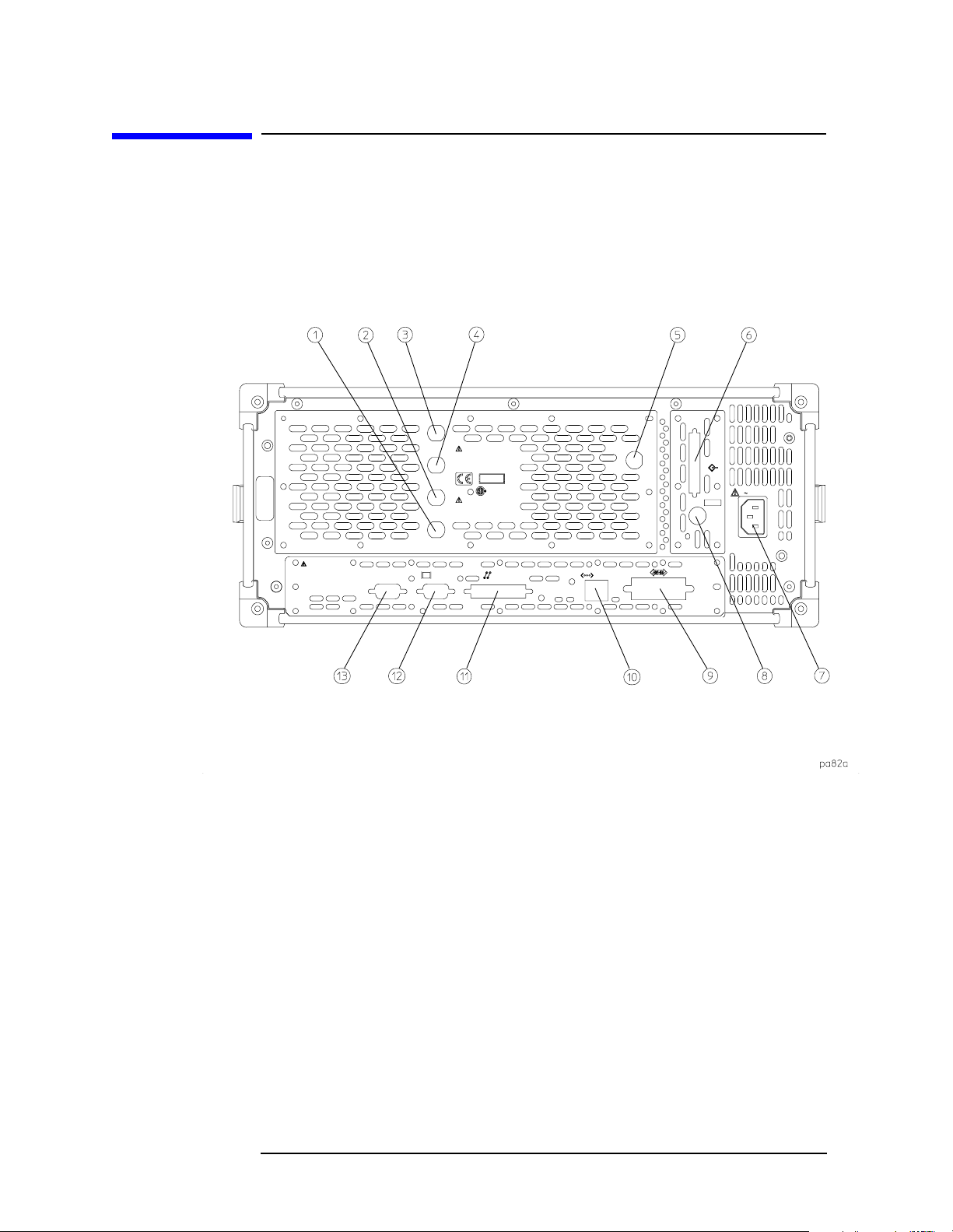
Rear Panel Description
The diagram below illustrates all rear panel connections. For further
explanation of labels found on the rear panel see the section on safety
considerations on page 49.
1. TRIGGER 2 OUT provides a transmitter tester trigger output. This is
used to synchronize other test equipment with the
transmitter tester.
TRIGGER 1 OUT provides a transmitter tester trigger output. This is
2.
used to synchronize other test equipment with the
transmitter tester.
EXT REF IN allows the input of a 1 to 30 MHz external frequency
3.
reference signal. The external reference frequency must
be entered by the user.
10 MHz OUT provides an output of the transmitter tester’s internal
4.
10 MHz frequency reference signal. This is used to lock
the frequency reference of other test equipment with
the transmitter tester. This is a switched output.
30 Chapter 1
Page 31

Getting Started
Rear Panel Description
5. TRIGGER IN The external trigger allows external triggering of
measurements. The external trigger accepts an
external trigger signal between
nominal impedance of 10k
−5 and +5 V, and has a
Ω. For more information on
triggering, see page 85.
SCSI Currently the SCSI connection can only be used to
6.
connect an external SCSI drive for firmware upgrades.
SCSI functionality will be fully implemented with a
future firmware update.
Line Power Input AC power line connection. The line voltage operates
7.
at nominally 115 V (47 to 440 Hz) or at nominally 230 V
(47 H to 66 Hz). The input power ranges for the power
supply are 90 to 132 V or 195 to 250 Vrms. The power
supply automatically senses the input power and
switches between these two ranges. There is no
customer replaceable power fuse. When on, the
instrument consumes less than 350 W; when in standby
less than 20 W.
KYBD This feature is not implemented. This feature will be
8.
implemented with a future firmware update. The
enables connection of an external PS-2 keyboard using
a 6-pin mini-DIN connector. If no keyboard is available
you can use the numeric keyboard and the
Alpha Editor
menu key feature to make the entries. The keyboard
must be plugged into the instrument prior to powering
the instrument on or the keyboard will not work.
GPIB The GPIB allows the connection of a General Purpose
9.
Interface Bus (GPIB) cable, which enables remote
instrument operation.
LAN-TP The LAN-TP connector can be used:
10.
- as a SICL server emulating IEEE 488.2 protocol
over LAN.
- for a telnet programming port that can be sent
SCPI commands.
- for a TCP/IP socket programming port that can be
sent SCPI commands.
- for anonymous FTP operations to retrieve a screen
“gif” or screen “xwd” file from the ftp/pub.
KYBD
NOTE For more information on remote programming with your transmitter
tester, refer to the programmer’s guide.
Chapter 1 31
Page 32

Getting Started
Rear Panel Description
11. PARAL L EL The PARALLEL connection supports remote printing.
12.
MONITOR The MONITOR allows connection of an external VGA
monitor, using a 15
13.
RS-232 The serial port RS-232 is not implemented. This feature
− pin mini D−SUB connector.
will be implemented with a future firmware update.
32 Chapter 1
Page 33

Display Annotation
Getting Started
Display Annotation
The annotation features explained below refers to the display that is
visible when your transmitter tester is in basic measurement mode;
this is the default state of the transmitter tester when it is turned on.
For explanations relating to unique measurement options such as GSM
or cdmaOne see the documentation that accompanies each mode.
1. Center Frequency annotation.
2. Trigger Source Indicator.
3. Vertical Scale dB/Division Indicator.
4. Reference Level Indicator (in dBm).
5. Active Function Area. The active function area displays
numeric entries. If you press a measurement key that
activates a function, its value will appear in the active
function area.
Chapter 1 33
Page 34

Getting Started
Display Annotation
6. Measurement Bar. Displays information about
measurements including some mode setup parameters.
7. Current Measurement Annotation.
8. The Annunciators bar displays annunciators that
indicate that hardware errors, other errors, or specific
instrument states, are detected in the instrument, as
explained below. Error indicators are shown in red text.
Where applicable, some states will appear in green,
indicating that the feature is active and performing
correctly. Informational annunciators are shown in
white text. To view error messages fully you will use
keys in the
Show Errors menu (see page 52). The current
error message with the highest priority will also appear
in the Status/Info Bar that appears at the bottom of the
display. The following annunciators are available:
Unlock - This annunciator indicates that one or
more of the internal phase-locked loops are unable to
maintain a phase-locked state.
Corr Off (corrections off) - This annunciator
appears when the
Corrections softkey is set to off.
Err (error) - This annunciator appears when an
error message is placed in the history error queue. It
will persist until you use the
Clear Error Queue(s) key
to clear the history error queue.
Ext Ref (external reference) - The green
Ext Ref
annunciator indicates that the external reference
has been selected and the instrument is locked to it.
The red
Ext Ref annunciator indicates that the
external reference has been selected, but the
instrument is not locked to that reference. Note that
the external reference on this instrument can be set
at any frequency between 1 and 30 MHz; if the
entered value does not correspond to the external
reference that is in use, a red
Ext Ref annunciator
will appear.
NOTE Be aware that the value entered for the external reference frequency
will persist, even after the instrument has been powered off. The user
must manually enter a new value for the external reference if a
different value is required, even if it corresponds with the default value.
Ext Ref annunciator will appear only if the external reference has
An
been activated by the user.
34 Chapter 1
Page 35

Getting Started
Display Annotation
ESec (even second clock) - The green ESec
annunciator indicates that the external even second
clock has been selected as the sync type and a sync
signal is present at the even second input (rear
panel Trigger In), and the measurement is using it
as the demodulation sync type. The red
ESec
annunciator indicates that an external even second
clock has been selected as the sync type but a sync
signal is not present at the even second input (rear
panel Trigger In). In this case, the error message
Even Second Clock Missing will appear in the
Status/Info bar at the bottom of the display. The
even second clock detection is updated every 2
seconds.
Klock (keyboard lock) - The keyboard can be locked
remotely using SYSTem:KLOck. The
Klock
annunciator will appear in white text when the
keyboard has been locked.
9. System Bar.
10. Time and Date.
11. Personality Mode Indicator.
12. Graph (Window) Title.
13. Averaging Indicator.
14. Remote Status Indicator. The remote status indicator
contains four letters: “R”,“ L”, “T”, and “S”. The current
status is indicated by the letters that are highlighted.
“R” indicates that the instrument is in remote mode.
“L” indicates a listen state. “T” indicates a talk state.
“S” indicates a service request.
15. Pass/Fail Status Indicator.
16. Menu Title.
17. Softkeys. A softkey that is currently active is
highlighted. Greyed-out softkeys are unavailable and
may require a password for use.
18. Span annotation.
19. Status/Info Bar. The current error message which has
the highest priority will appear in the Status/Info Bar.
A programmer can also send a message to the
Status/Info bar using a SCPI command.
Chapter 1 35
Page 36

Getting Started
Installing Optional Measurement Personalities
Installing Optional Measurement Personalities
When you install a measurement personality, follow this process.
1. Install the measurement personality firmware into the instrument.
(See the supplied installation instructions.)
2. Enter a license key number that enables the measurement
personality. (Refer to the “License Key Numbers” section below.)
Adding additional measurement personalities requires purchasing a
retrofit kit for the desired option. The retrofit kit contains the
measurement personality firmware. A license key certificate is also
included in the kit. It documents the license key number that is for your
specific option and instrument serial number. Installation instructions
are included with the retrofit kit.
Available Personality Options
The option designation consists of three characters, as shown in the
Option column of the table below.
Available Personality Options
GSM measurement personality BAH
EDGE (with GSM) measurement personality
cdmaOne measurement personality BAC
NADC, PDC measurement personalities BAE
iDEN measurement personality HN1
W-CDMA measurement personality BAF
cdma2000 measurement personality B78
a. Available as of the print date of this guide.
b. For instruments that already have Option BAH licensed, order
E4406AU Option 252 to add EDGE (with GSM).
a
b
Option
202
36 Chapter 1
Page 37

Getting Started
Installing Optional Measurement Personalities
Loading the Optional Personality
The installation instructions require you to know three pieces of
information about your instrument: the amount of memory available,
the Host ID, and the instrument serial number.
Required Information: Key Path:
Instrument
Memory:
__________________
Host ID:
__________________
Instrument
Serial Number:
__________________
System, File System
(This key is grayed out. The total amount of
memory in your instrument will be the sum
of the
Used memory and the Free memory)
System, Show System, Host ID
(It is shown on the display.)
System, Show System, Serial Number
You must load the desired option into your instrument memory. This
usually requires updating the instrument firmware so that it is
compatible with the new option. Loading can be done from a CD-ROM
or a www location.
You cannot fit all of the available measurement personalities in the
instrument memory at the same time. The approximate memory
requirements for the options are listed below. These numbers are worst
case examples. Many options share share components. The total
memory usage of multiple options may not be exactly equal to the
combined total.
Available Personality Options File Size (VSA - A.05.20)
GSM measurement personality 2.3 MB
EDGE (with GSM) measurement personality 3.2 MB
cdmaOne measurement personality 1.9 MB
NADC measurement personalities 1.2 MB
PDC measurement personalities 1.3 MB
iDEN measurement personality 1.7 MB
W-CDMA measurement personality
cdma2000 measurement personality
**Shared measurement library 1.5 MB
4.1 MB
3.7 MB
a
a
a. This application uses the shared library, so you have to add its
memory requirements to this value.
Chapter 1 37
Page 38

Getting Started
Installing Optional Measurement Personalities
The Exit Main Firmware key is used during the firmware installation
process. This key is only for use when you want to update firmware
using a LAN connection. The
Exit Main Firmware key halts the operation
of the instrument firmware so you can install an updated version of
firmware using a LAN connection. Instructions for loading future
firmware updates are available at the following URL:
www.agilent.com/find/vsa/
Viewing a License Key
Measurement personalities purchased with your instrument have been
installed and enabled at the factory. You will receive a unique License
Key number with every measurement personality purchased. The
license key number is a hexadecimal number that is for your specific
measurement personality, instrument serial number and host ID. It
enables you to install, or reactivate that particular personality.
Follow these steps to display the unique license key for a measurement
personality that is already installed in your instrument:
1. Press
System, Install, Choose Option. The Choose Option key accesses the
alpha editor. Use the alpha editor to enter letters (upper-case) and
the front-panel numeric keys to enter digits for a personality option
that is already installed in the instrument.
2. Press the
number for your instrument will now appear on the
Done key on the alpha editor menu. The unique license key
License Key
softkey.
You will want to keep a copy of your license key number in a secure
location. Please enter your license key numbers below for future
reference. If you should lose your license key number, call your nearest
Agilent Technologies service or sales office for assistance.
License Key Numbers for Instrument with Serial # ________
For Option______________ the license key number is _____________________
For Option______________ the license key number is _____________________
For Option______________ the license key number is _____________________
For Option______________ the license key number is _____________________
For Option______________ the license key number is _____________________
For Option______________ the license key number is _____________________
If you purchase an option later, you will receive a certificate that
indicates the unique license key that you will need for you to install
that option on your particular serial number instrument.
38 Chapter 1
Page 39

Getting Started
Installing Optional Measurement Personalities
NOTE You will need to enter a license key number only if you purchase an
additional measurement personality at a later date, or if you want to
reactivate a measurement personality that has been deactivated.
Installing a License Key
NOTE Also follow this procedure to reinstall a license key number that has
been deleted during an uninstall process, or lost due to a memory
failure.
To install a license key number for the selected option, use the following
procedure:
1. Press
System, Install, Choose Option . The Choose Option key accesses
the alpha editor menu. Use the alpha editor to enter letters
(upper-case) and the front-panel numeric keys to enter numbers for
the option designation. Then press the
Done key. As you enter the
option, you will see your entry in the active function area of the
display.
NOTE You must already have entered the license key for the GSM option BAH
before you can enter the license key for the EDGE retrofit option 252.
2. Press
License Key. Enter the letters/digits of your license key. You will
see your entry in the active function area of the display. When you
have completed entering the license key number, press the
3. Press the
The message “
Install Now key.
New option keys become active after reboot.”
Done key.
will appear. If you want to proceed with the installation, press the
Yes key and cycle the instrument power off and then on. Press the No
key if you wish to cancel the installation process.
Using the Uninstall Key
The following procedure removes the license key number for the
selected option. This will make the option unavailable for use, and the
message “
bar at the bottom of the display. Please write down the 12-digit license
key number for the option before proceeding. If that measurement
personality is to be used at a later date you will need the license key
number to reactivate the personality firmware.
Application Not Licensed” will appear in the Status/Info
Chapter 1 39
Page 40

Getting Started
Installing Optional Measurement Personalities
NOTE Using the Uninstall key does not remove the personality from the
instrument memory, and does not free memory to be available to install
another option. If you need to free memory to install another option,
refer to the instructions for loading firmware updates located at the
URL: www.agilent.com/find/vsa/.
1. Press
Pressing the
System, More(1 of 3), More(2 of 3), Uninstall, Choose Option.
Choose Option key will activate the alpha editor menu.
Use the alpha editor to enter the letters (upper-case) and the
front-panel numeric keyboard to enter the digits (if required) for the
option, then press the
Done key. As you enter the option, you will see
your entry in the active function area of the display.
2. Press the
option. Press the
process. Press the
Uninstall Now key after you have entered the personality
Yes key if you want to continue the uninstall
No key to cancel the uninstall process.
3. Cycle the instrument power off and then on to complete the uninstall
process.
40 Chapter 1
Page 41

Getting Started
Cables for Connecting to the Serial Port (RS-232)
Cables for Connecting to the Serial Port
(RS-232)
There are a variety of cables and adapters available for connecting to
PCs, and printers. Several of these are documented in the following
wiring diagrams. You need to find out what connections your equipment
uses to identify the cables and/or adapters that you will need.
HP 34398A
RS-232
Cable Kit This kit comes with an RS-232, 9-pin female to 9-pin
female null modem/printer cable and one adapter 9-pin
male to 25-pin female (HP part number 5181-6641).
The adapter is also included in HP 34399A RS-232
Adapter Kit.
HP 34399A
RS-232
Adapter Kit This kit includes four adapters to go from DB9 female
cable (HP 34398A) to PC/printer DB25 male or female,
or to modem DB9 female or DB25 female.
Figure 1-5 HP 24542U Cable
Figure 1-6 HP F1047-80002 Cable
Chapter 1 41
Page 42

Getting Started
Cables for Connecting to the Serial Port (RS-232)
Figure 1-7 HP 24542G/H Cable
Figure 1-8 HP 92219J Cable
Figure 1-9 HP 13242G Cable
42 Chapter 1
Page 43

Figure 1-10 HP 24542M Modem Cable
Figure 1-11 HP C2913A/C2914A Cable
Getting Started
Cables for Connecting to the Serial Port (RS-232)
Figure 1-12 Mouse Adapter (typical)
Chapter 1 43
Page 44

Getting Started
Cables for Connecting to the Serial Port (RS-232)
Figure 1-13 HP 24542U Cable with 5181-6641 Adapter
Figure 1-14 HP 24542U Cable with 5181-6640 Adapter
Figure 1-15 HP 24542U Cable with 5181-6642 Adapter
44 Chapter 1
Page 45

Cables for Connecting to the Serial Port (RS-232)
Figure 1-16 HP 24542U Cable with 5181-6639 Adapter
Figure 1-17 HP F1047-80002 Cable with 5181-6641 Adapter
Getting Started
Figure 1-18 HP F1047-80002 Cable with 5181-6640 Adapter
Chapter 1 45
Page 46

Getting Started
Cables for Connecting to the Serial Port (RS-232)
Figure 1-19 HP F1047-80002 Cable with 5181-6642 Adapter
Figure 1-20 HP F1047-80002 Cable with 5181-6639 Adapter
46 Chapter 1
Page 47

Getting Started
Safety Considerations
Safety Considerations
This section covers safety considerations relating to the installation and
use of the instrument.
Instrument Installation
Install the instrument so that the detachable power cord is readily
identifiable and is easily reached by the operator. The detachable power
cord is used to completely disconnect the instrument. The front panel
switch is only a standby switch which maintains standby power to some
parts of the instrument. It does not disconnect the instrument from the
power source. Alternatively, an externally installed switch or circuit
breaker (which is readily identifiable and is easily reached by the
operator) may be used as a disconnecting device.
The input power ranges for the power supply are 90 to 132 V, or 195 to
250 Vrms. The power supply automatically senses the input power and
switches between these two ranges. There is no customer replaceable
power fuse.
WARNING The power cord is connected to internal capacitors that may
remain live for 5 seconds after the plug is disconnected from its
power supply.
WARNING If this product is to be energized via an external
autotransformer for voltage reduction, make sure that its
common terminal is connected to a neutral (earthed pole) of the
power supply.
CAUTION This instrument has autoranging line voltage input, be sure the supply
voltage is within the specified range.
CAUTION VENTILATION REQUIREMENTS: When installing the product in a
cabinet, the convection into and out of the product must not be
restricted. The ambient temperature (outside the cabinet) must be less
than the maximum operating temperature of the product by 4° C for
every 100 watts dissipated in the cabinet. If the total power dissipated
in the cabinet is greater than 800 watts, then forced convection must be
used.
Chapter 1 47
Page 48

Getting Started
Safety Considerations
Instrument Operation and Maintenance
The following warnings explain conditions which affect the safe
operation of the instrument.
WARNING If this instrument is not used as specified, the protection
provided by the equipment could be impaired. This product
must be used in a normal condition (in which all means for
protection are in tact) only.
WARNING To prevent electrical shock, disconnect the E4406A from mains
before cleaning. Use a dry cloth or one slightly dampened with
water to clean the external case parts. Do not attempt to clean
internally.
Explanation of Safety Symbols that are on the Instrument
The following list describes all safety symbols that are on the front and
rear panels of the transmitter tester.
The instruction documentation symbol. The product is marked with this
symbol when it is necessary for the user to refer to the instructions in the
documentation.
This symbol is used to mark the ON position of the power line switch.
This symbol is used to mark the OFF position of the power line switch.
This symbol is used to mark the STANDBY position of the power line switch.
This symbol indicates that the input power required is AC.
This symbol is used to mark the STANDBY/OFF position of the power line
switch.
This symbol is used to mark the On position of the power line switch.
48 Chapter 1
Page 49

Getting Started
Safety Considerations
Safety Considerations for Service Personnel
NOTE No one other than qualified service personnel are allowed to remove
the cover of the instrument. The following warnings apply to service
personnel. These warnings are found on the rear panel of the
instrument.
To Remove Outer Cover, Remove Strap Handle, 4 Bottom
Feet, and 4 Rear Feet.
To Remove CPU Assembly Unplug All Boards Connected to
CPU. When Removing CPU Keep Perpendicular with Rear
Panel
Chapter 1 49
Page 50

Getting Started
Safety Considerations
50 Chapter 1
Page 51

2 Using System Features
System keys access features that are used with all modes, including
alignment, configuring I/O, and file management.
51
Page 52

Using System Features
Using System Keys
Using System Keys
System features are accessed through the System front panel key. These
are features that are not dependent on the currently selected
application mode or the particular measurement being made. They
apply to all modes and measurements.
System key also performs the LOCAL function. If the instrument
The
was previously being controlled remotely by a computer, pressing the
System key will reactivate the front panel keys.
Print feature keys are accessed through the front panel Print Setup and
Print keys, which are explained on page 63.
File feature keys are accessed through the File and Save menu keys,
which are explained on page 67.
Each description of a system feature begins with a table that shows the
key path for all keys related to that feature.
NOTE Most of the system features are not affected by pressing the Preset key
or by cycling the instrument power. These features will retain the last
value set by the user. Press
System, More, Restore Sys Defaults, Yes to
reset the System parameters back to the factory defaults.
Install and Uninstall
The Install and Uninstall keys, which enable you to install and remove
measurement personalities, are described separately on page 36 of the
Getting Started chapter.
52 Chapter 2
Page 53

Key Locations
All system, service, and basic features can be located by using the key
access table below. The key access path describes the key sequence you
enter to access the particular key.
Some features can only be used when specific measurements are active.
If a feature is not currently valid the key label for that feature will
appear as lighter colored text, will be greyed-out, or will not be
displayed at all.
Table 2-1 Key Access Locations
Key Key Access Path
10 MHz Out System/Reference/
50 MHz Amptd MODE/Service/
50 MHz Ref Input/Input Port/
Using System Features
Key Locations
ADC Dither Meas Setup/More(1 of 2)/Advanced/ More(1 of 2)/
ADC Range Meas Setup/More(1 of 2) / Advanced /
Note: This feature is used when measure is set to either
spectrum or waveform.
Adjust Now System/Alignments/Align Subsystem/Align 50 MHz Reference/
Note: Requires Password
Advanced Meas Setup/More(1 of 2)
Align 50 MHz
Reference
Align ADC System/Alignments/Align Subsystem/
Align All Now System/Alignments/
Align IF System/Alignments/Align Subsystem/
Align RF System/Alignments/Align Subsystem/
Alignments System/
Align Subsystems System/Alignments/
All View/Trace/Trace Display/
Alpha Editor The Alpha Editor is accessed by following the Menu Access
System/Alignments/Align Subsystem/
Note: Requires Password
Paths that accompany the following key entries: Choose Option,
License Key, and Host Name.
AMPLITUDE/
Y Scale
Auto Meas Setup/More(1 of 2)/Advanced/ More (1 of 2)/Data Packing/
Front Panel
Chapter 2 53
Page 54

Using System Features
Key Locations
Table 2-1 Key Access Locations
Key Key Access Path
Auto Meas Setup/More(1 of 2)/ Advanced /ADC Range /
Note: This feature is used when measurement is set to either
spectrum or waveform.
Auto Align System/Alignments/
AutoPeak Meas Setup/More(1 of 2)/ Advanced /ADC Range /
Note: This feature is used when measurement is set to either
spectrum or waveform.
AutoPeakLock Meas Setup/More(1 of 2)/ Advanced /ADC Range /
Note: This feature is used when measurement is set to either
spectrum or waveform.
Auto Trig Mode Setup/ Trigger/
Note: This feature is used when measurement is set to either
spectrum or waveform.
Average View/Traces/ Display Traces/
Average Meas Setup/
Note: This feature is used when measurement is set to either
spectrum or waveform.
Avg Mode Meas Setup/ Average/
Note: This feature is used when measurement is set to either
spectrum or waveform.
Avg Number Meas Setup/Average/
Note: This feature is used when measurement is set to either
spectrum or waveform.
Avg Trace Marker/More(1 of 2)/ Marker Trace/
Avg Type Meas Setup/ Average/
Note: This feature is used when measurement is set to either
spectrum or waveform.
Band Power Marker/ Function/
Basic MODE/
Blackman Meas Setup/More(1 of 2)/ Advanced/ FFT Window/
Blackman- Harris Meas Setup/More(1 of 2) /Advanced / FFT Window/ More(1 of 2)/
BMP Print Setup/Print To: File/File Type
cdmaOne MODE/
Center Freq FREQUENCY/Channel/
Choose Option System/More(1 of 3)/More(2 of 3) /Install/
Choose Option System/More(1 of 3)/More(2 of 3) /Uninstall/
54 Chapter 2
Page 55

Using System Features
Key Locations
Table 2-1 Key Access Locations
Key Key Access Path
Clear Error Queue(s) System/Show Errors/
Color Print Print Setup/Print To: Printer/Printer Type: Custom/Define
Custom/Color Printer: Yes
Color Printer Print Setup/Print To: Printer/Printer Type: Custom/Define
Custom
Comb Input/IF Align Signal/Signal Type/
Config I/OSystem/
Corrections System/Alignments/
Counts MODE/Basic, Meas Setup
Current View/Trace/ Trace Display/
Current Trace Marker/ More(1 of 2)/Marker Trace/
Custom Print Setup/Print To: Printer/Printer Type
CW Input/IF Align Signal/Signal Type/
Data Packing Meas Setup/More(1 of 2)/
Decimation Meas Setup/More(1 of 2)/ Advanced/More (1 of 2)/
Define Custom Print Setup/Print To: Printer
Delay Mode Setup/Trigger/Ext Front/
Delay Mode Setup/Trigger/Ext Rear/
Delay Mode Setup/Trigger/RF Burst/
Delay Mode Setup/Trigger/Video/
Delta Marker/
Diagnostics System/More (1 of 3)/
Note: Requires Password
Display Front Panel
Emulated GPIB Name System/Config I/O/ SICL Server
Emulated GPIB
Logical Unit
System/Config I/O/ SICL Server
Emulated GPIB
Address
Enter Front Panel
ESC Front Panel
System/Config I/O/ SICL Server
Chapter 2 55
Page 56

Using System Features
Key Locations
Table 2-1 Key Access Locations
Key Key Access Path
Exit Main Firmware System/ More (1 of 3)/More (2 of 3)/ Install/
Ext Front Mode Setup/ Trigger/
Ext Rear Mode Setup/ Trigger/
Fast ACP Mode/ACP/Meas Setup/More(1 of 2)/
FFT Length Meas Setup/More(1 of 2)/ Advanced/FFT Size/
Note: This feature is used when measurement is set to spectrum.
FFT Size Meas Setup/ More(1 of 2)/ Advanced/
Note: This feature is used when measurement is set to spectrum.
FFT Window Meas Setup/ More(1 of 2)/ Advanced/
Note: This feature is used when measurement is set to spectrum.
File Front Panel
File System System/More(1 of 3)/ More(2 of 3)/
File Location Print Setup/Print to File
File Type Print Setup/Print to File
Flat Top Meas Setup/More(1 of 2)/ Advanced/ FFT Window/
Frame MODE/Basic, Meas Setup/Trig Source
Free Run Meas Setup//Trig Source/
FREQUENCY/
Channel
Freq Ref System/ Reference/
Front Panel Test MODE/Service/More(1 of 2)/
Function Marker/ More(1 of 2)/
Gaussian Meas Setup/More(1 of 2) /Advanced / FFT Window/
GIF Print Setup/Print To: File/File Type
GPIB Address System/Config I/O/
GSM MODE/
Hamming Meas Setup/More(1 of 2) /Advanced / FFT Window/
Front Panel
Hanning Meas Setup/More(1 of 2) Advanced / FFT Window/
Help Front Panel
Host Name System/Config I/O/
IF Align Input/ Input Port/
56 Chapter 2
Page 57

Table 2-1 Key Access Locations
Key Key Access Path
IF Align Signal Input/
Image Print Setup/Print to File
Instrument Name System/Config I/O/ SICL Server
Using System Features
Key Locations
Instrument Logical
Unit
Input Front Panel
Input Atten Input/
Input Port Input/
Install System/More(1 of 3)/ More(2 of 3)/
Install Now System/ More (1 of 3)/ More (2 of 3)/ Install/
IP Address System/Config I/O/
I/Q Input Z Input/
I/Q Waveform Marker/Trace/
System/Config I/O/ SICL Server
Note: This feature is used when measurement is set to either
spectrum or waveform.
K-B 70 dB Meas Setup/More(1 of 2)/ Advanced / FFT Window/More(1 of 2)/
K-B 90 dB Meas Setup/More(1 of 2)/ Advanced / FFT Window/More(1 of 2)/
K-B 110 dB Meas Setup/More(1 of 2)/ Advanced / FFT Window/More(1 of 2)/
Landscape Print Setup/Print To: Printer/Printer Type: Custom/Orientation
Language Print Setup/Print To: Printer/Printer Type: Custom/Define
Custom
Length Ctrl Meas Setup/More(1 of 2)/ Advanced/FFT Size/
Note: This feature is used when measurement is set to spectrum.
Level Mode Setup/Trigger/Ext Front/
Level Mode Setup/Trigger/Ext Rear/
License Key System/ More (1 of 3)/ More (2 of 3)/ Install/
Line Meas Setup/ Trig Source/
Load State File/
Local
(System) Note: Press the front panel System key to change from remote to
local control of the instrument
Log-Pwr Avg Meas Setup/Average/Avg Type/
Chapter 2 57
Page 58

Using System Features
Key Locations
Table 2-1 Key Access Locations
Key Key Access Path
Long Meas Setup/More(1 of 2)/
Advanced/ More (1 of 2)/
Data Packing/
Manual Meas Setup/More(1 of 2)/ Advanced /ADC Range/
Note: This feature is used when measurement is set to either
spectrum or waveform.
Marker Front Panel
Maximum
Connections
Mrkr All Off Marker/More(1 of 2)/
Maximum Meas Setup/ Average/ Avg Type/
Max Total Pwr Input/
Measure Front Panel
Meas BW MODE/Basic, Meas Setup
Meas Control Front Panel
Meas Interval MODE/Basic, Meas Setup
Meas Setup Front Panel
Medium Meas Setup/More(1 of 2)/Advanced/ More (1 of 2)/Data Packing/
Minimum Meas Setup/Average/ Avg Type/
Min Pnts/ RBW Meas Setup/More(1 of 2)/ Advanced/FFT Size/
System/Config I/O/ SICL Server
Note: This feature is used when measurement is set to spectrum.
MODE Front Panel
Mode Setup Front Panel
Next Window Front Panel
Noise Marker/ Function/
Normal Marker/
Off Marker/
Orientation Print Setup/Print To: Printer
Pause Meas Control
PCL3 Print Setup/Print To: File/File Type
PCL5 Print Setup/Print To: File/File Type
Peak Level Mode Setup/ Trigger/ RF Burst/
58 Chapter 2
Page 59

Table 2-1 Key Access Locations
Key Key Access Path
Power Stat CCDF MODE/Basic, Meas Setup
Using System Features
Key Locations
Portrait
Pre-ADC BPF Meas Setup/ More(1 of 2)/ Advanced/
Print Setup/Print To: Printer/Printer Type: Custom/Orientation
Note: This feature is used when measurement is set to either
spectrum or waveform.
Pre-FFT BW Meas Setup/ More(1 of 2)/ Advanced/
Note: This feature is used when measurement is set to spectrum.
Pre-FFT Fltr Meas Setup/ More(1 of 2)/ Advanced/
Note: This feature is used when measurement is set to spectrum.
Print Front Panel
Printer Print Setup/
Printer Type Print Setup/Print To: Printer
Print Setup Front Panel
Prints/Page Print Setup/ Print To: Printer
Print To Print Setup/
Pulse Input/IF Align Signal/Signal Type/
Pwr Avg (RMS) Meas Setup/Average/Avg Type/
Pwr vs Time MODE/Service/
RBW Filter Meas Setup/ More(1 of 2)/ Advanced
Note: This feature is used when measurement is set to spectrum.
Reference System/
Ref Position AMPLITUDE/Y Scale/ for spectrum or waveform - or -
SPAN/XScale/ for waveform.
Ref Values AMPLITUDE/Y Scale/ for spectrum or waveform - or -
SPAN/XScale/ for waveform.
Res BW Meas Setup/
Note: This feature is used when measurement is set to either
spectrum or waveform.
Restart Front Panel
Restore Align Defaults System/Alignments/
Restore Meas
Defaults
Restore Sys
Defaults
Meas Setup/ More(1 of 2)
System/ More(1 of 3)/ More (2 of 3) /
Chapter 2 59
Page 60

Using System Features
Key Locations
Table 2-1 Key Access Locations
Key Key Access Path
Return Front Panel
RF Input/Input Port/
Align RF System/Alignments/Align Subsystem/
RF Burst Mode Setup/ Trigger/
RF Envelope View/Trace/
Note: This feature is used when measurement is set to
waveform.
RF Envelope Marker/Trace/
Note: This feature is used when measurement is set to
waveform.
RF Inp Level System/Alignments/Align Subsystem/ Align 50 MHz Reference/
Save Front Panel
Save State File/ or Save/
Scale Coupling AMPLITUDE/Y Scale/ for spectrum or waveform - or -
SPAN/XScale/ for waveform.
Scale/Div AMPLITUDE/Y Scale/ for spectrum or waveform - or -
SPAN/XScale/ for waveform.
SCPI LAN System/Config I/O/
Search Front Panel
Select Marker/
Sensors MODE/Service/
Server System/Config I/O/ SICL Server
Service MODE/
Service Password System/More(1 of 3)/Show System/
Shape Marker/More (1 of 2)/
Short Meas Setup/More(1 of 2)/ Advanced/More (1 of 2)/Data Packing/
Show Errors System/
Show System System/More(1 of 3)/
SICL Server System/Config I/O/
Signal Amptd Input/IF Align Signal/
Signal Rate Input/IF Align Signal/
Signal Type Input/IF Align Signal/
60 Chapter 2
Page 61

Table 2-1 Key Access Locations
Key Key Access Path
Slope Mode Setup/Trigger/Ext Front
Slope Mode Setup/Trigger/Ext Rear/
Slope Mode Setup/Trigger/RF Burst/
Slope Mode Setup/Trigger/Video/
Socket Port System/Config I/O/ SCPI Lan
Span Meas Setup/
Using System Features
Key Locations
SPAN/
X Scale
Spectrum View/Trace/
Front Panel
Note: This feature is used when measurement is set to spectrum.
Spectrum Marker/Trace/
Note: This feature is used when measurement is set to spectrum.
Spectrum Avg Marker/Trace/
Note: This feature is used when measurement is set to spectrum.
Spectrum
(Freq Domain)
Spectrum
(Freq Domain)
Store Abs Ampl to
EEROM
Subnet Mask
Sweep Time Meas Setup/ Can be accessed when measure is set to waveform.
System Front Panel
Telnet P o rt System/Config I/O/ SCPI Lan
MODE/Service/
MODE/Basic/
System/Alignments/Align Subsystem/ Align 50 MHz Reference/
System/Config I/O
Timebase Freq MODE/Service/
Trace Marker/
Trace Display View/Trace/
Trigger Mode Setup/
Note: This feature is used when measurement is set to either
spectrum or waveform.
Trig Holdoff Mode Setup/ Trigger/
Note: This feature is used when measurement is set to either
spectrum or waveform.
Chapter 2 61
Page 62

Using System Features
Key Locations
Table 2-1 Key Access Locations
Key Key Access Path
Trig Source Meas Setup/
Note: This feature is used when measurement is set to either
spectrum or waveform.
Uniform Meas Setup/More(1 of 2)/Advanced / FFT Window/
Uninstall System/ More (1 of 3)/ More (2 of 3)/
Uninstall Now System/ More (1 of 3)/ More (2 of 3)/ Uninstall/
Verbose System/Show Errors/
Video Mode Setup/ Trigger/
View/Trace Front Panel
Visible Align System/Alignments/
Voltage Avg Meas Setup/Average/ Avg Type/
Waveform
(Time Domain)
Waveform
(Time Domain)
WindowLength Meas Setup/More(1 of 2)/ Advanced/FFT Size/
MODE/Basic/
MODE/Service/
Note: This feature is used when measurement is set to spectrum.
WMF Print Setup/Print To: File/File Type
Zoom Front Panel
62 Chapter 2
Page 63

Using System Features
Using Print and Print Setup Functions
Using Print and Print Setup Functions
Keys in the Print Setup menus enable you to print displayed screen
images to a variety of printers, as a file in a variety of formats to the C:
drive flash memory, or to the built-in floppy disk drive. The
used to execute choices made in the
Print Setup menus.
Printing a Displayed Screen
1. Connect a compatible printer via the parallel port on the rear panel.
Print key is
2. Press
3. Press
4. Press Define Custom, then select a
Print Setup, then toggle the Print To key to select Printer.
Printer Type, then select Custom.
Language, either PCL3 or PCL5.
(In general, modern laser printers use PCL5 while inkjet printers
use PCL3.)
5. Select Color Printer
Yes / No depending on the capability of the
printer.
6. If your printer uses PCL5 you can select Orientation, then
Por trait or Landscape as appropriate. The orientation feature is
unavailable with PCL3 printers, which always default to portrait
orientation.
7. Toggle Color Print
the
Color Printer key (see above) is set to Yes.
8. Toggle
Prints /Page (1 or 2) to select to print either one image (in
- On/Off to enable or disable color printing once
portrait orientation) covering half a page, or two images (in portrait
orientation), each covering half the page.
9. Press the
Print key. A copy of the current display screen will be sent
to the printer according to the parameters set above.
10. If you want to reprint the most recently printed page, press
Reprint.
11.If you want to eject a page from a compatible printer, toggle
More (1 of 2), then Eject Page.
12. If a printer failure occurs (for example, if the printer hangs up),
Reset Printer. It may also be necessary to cycle printer power.
press
Chapter 2 63
Page 64

Using System Features
Using Print and Print Setup Functions
The following table illustrates the Print Setup menu. Level 1 shows key
choices available when the front panel key is pressed. Level 2 shows key
choices available when
Print To is set to Printer and Level 1 keys are
pressed.
Front Panel Key Level 1 Level 2
Print Setup Print To with Printer
selected
Printer Type
Define Custom
Orientation
(Only active
for PCL5 language;
printers with PCL3
language default to
portrait orientation)
Color Print
when
Yes- see above.)
Prints/Page 1 / 2
More (1 of 2)
Reprint
(Only active
Color Print is set to
(Only active
after initial printing.)
Eject Page
None
Custom
Language PCL3/PCL5
Color Printer Yes/No
Portrait
Landscape
On/Off
Reset Printer
More (2 of 2)
64 Chapter 2
Page 65

Using System Features
Using Print and Print Setup Functions
Printing a Screen Image to a File on A: or C: Drives
1. Press Print Setup, Print To. Toggle the Print To key to select File.
2. Press the
File Type key, then select between gif, bmp, and wmf
formats.
3. To print a file to the floppy drive, toggle the
File Location key to A: and
insert a 3.5” HD floppy disc, formatted for MS-DOS, into the front
panel disk drive.
To print a file to the internal flash memory, toggle the File Location
key to
4. Select the Image format to be stored on the disk. Use
C:.
Normal to store
an image that is identical to the currently displayed image, with a
black background. Use Invert, which provides a a light background
with a dark trace, to minimize ink and toner consumption.
5. Press HCOPy Dest, then select
Printer. This enables you to generate
up to six files containing screen images.
Note: if
HCOPy Dest is set to FPanel only one file can be saved to
memory or a floppy disk. Any subsequent screen files will overwrite
the file currently saved in the A: or C: drives. For these reasons,
Printer is usually the preferred selection.
6. Press the front panel
PRINT key. If you have set HCOPy to Printer, six
filenames will appear in the softkeys: screen1.xxx, screen2.xxx,
screen3.xxx, screen4.xxx, screen5.xxx, and screen6.xxx (the xxx
extension will be gif, bmp, or wmf, depending on the file type selected
File Type). The destination drive name will also be displayed.
in
Press the appropriate screen#.xxx key. Files written to the A: drive
will be located at A:
be accessed by the following path:
screen#.xxx. Files written to the C: drive may
/users/ftp/pub/screen#.xxx.
Six files may be stored at the same time to either location. Any
subsequent files stored to the same filename will overwrite the
existing file
7. The disk may be removed from the A: drive once the LED on the
disk drive is off. Any files you have saved are now available to be
printed through use of an external computer and printer, or to be
imported into an electronic document.
Files located on the C: drive may be retrieved over the LAN by
ftp
with the use of an external computer.
Chapter 2 65
Page 66

Using System Features
Using Print and Print Setup Functions
The following table illustrates the keys used and key choices available
to print a screen image to either the A: internal floppy disk drive or the
internal C: drive flash memory. Level 1 shows key choices available
when the front panel key is pressed. Level 2 shows key choices available
when
Print To is set to File and Level 1 keys are pressed.
Front Panel Key Level 1 Level 2
Print Setup Print To with File
selected
File Type GIF
BMP
WMF
File Location A:/C:
Image Invert/Normal
Print
HCOPy Dest
FPanel/Printer
(the six screen files
shown below are
available only when
HCOPy Dest is set to
Printer.)
screen1.xxx (xxx
depends on
screen2.xxx
screen3.xxx
screen4.xxx
screen5.xxx
screen6.xxx
File Type)
= Print to Key
Printer
66 Chapter 2
Page 67

Using System Features
Using File and Save Keys
Using File and Save Keys
The File and Save keys enable you to save instrument states to memory
and to load instrument states into the instrument from memory. For
instructions on how to save a screen image to a floppy disc, see Saving a
Screen Image to a Floppy Disc on page 63.
Front Panel Key Level 1 Level 2 Level 3
File Load State numeric entry Enter
Save
Save State
numeric entry Enter
numeric entry Enter
Loading a State
1. Press File, Load State. A label in the active function area will read
Load State.
2. Use the numeric keypad to enter the number of the register from
which you desire to retrieve a state (you can retrieve states from
registers 0 to 19), then press the
Enter key.
Saving a State
1. Press File, Save State or press the front panel Save key. An active
function labeled
2. Use the numeric keypad to enter the desired state number (you can
enter values from 0 to 19), then press the
Save State will appear.
Enter key.
Chapter 2 67
Page 68

Using System Features
Using File and Save Keys
Using the Alpha Editor Keys
The alpha editor enables you to enter text. All text entries are displayed
in the active function area.
Level 1Level 2Level 3Example
ABCDEFG abcdefg ():;,’ V
HIJKLMN hijklmn _!? ~ W
OPQRSTU opqrstu + - * / <> = X
VWXYZ vwxyz |/\{} [] Y
Done Done @ # $% ^ & Z
Space Space Space
More (1 of 3) More (2 of 3) More (3 of 3)
1. Pressing a key that requires you to enter a string gives you access to
the alpha editor.
of those keys. When one of these keys is pressed, you will see the
menu which is shown in level 1 of the table above.
Choose Option, License Key, and Host Name are some
2. To enter an upper case letter, press the key which contains the letter
you wish to select. In the example table above, pressing
you select the key labelled upper case
the active function area. Press
letters and
More (2 of 3) to access mathematical symbols and
More (1 of 3) to access the lower case
Y. The Y will then appear in
VWXYZ lets
punctuation marks.
3. To enter a digit, 0 through 9, use the numeric keypad.
4. To enter a space, press the
Space key, which is available on both the
letters and the symbols Alpha Editor menus.
5. Press the
Return front panel key to return to the previous menu
without entering characters.
6. If you need to correct a character you have entered, you can use the
backspace key to move the cursor in the active function area to the
character you need to correct.
7. Once you have completed entering all characters, press the
8. Pressing the
ESC key at any time prior to pressing the Done key will
Done key.
clear the new entry and leave the previous entry unchanged.
68 Chapter 2
Page 69

Using System Features
Using Input/Output Configuration Keys
Using Input/Output Configuration Keys
There are several keys available to help configure the instrument front
panel and rear panel inputs/outputs. These include the various buses,
external reference, and other types of I/O.
Configuring I/O
Press System, Config I/O to access keys and menus that enable you to
identify and change the current GPIB address, to identify and change
various LAN settings.
Front Panel Key Level 1 Level 2 Level 3/Entry
System Config I/O GPIB Address
IP Address
Host Name Alpha Editor
Subnet Mask
SCPI LAN Telnet Port
Socket Port
SICL Server Server
Maximum
Connections
Instrument Name
Instrument Logical
Unit
Emulated
GPIB Name
Emulated GPIB
Logical Unit
Emulated
GPIB Address
Ethernet Addr
• GPIB Address - Shows the current GPIB address (18 is the default
setting) and allows you to change this value. The new value is
displayed in the active function area. The GPIB port is always
active.
Chapter 2 69
Page 70

Using System Features
Using Input/Output Configuration Keys
• IP Address - Changes the IP (internet protocol) address, domain
name and node (host) name for the instrument. The IP address of
the instrument can be changed by entering a numeric address
composed of numbers and decimal points.
• Host Name - Displays the host name of the instrument. Pressing
the key activates the alpha editor, which enables you to change the
host name. However, this will not change your LAN system
representation of the host name. You must work through your local
system administrator to change the host name. Changing it in the
instrument only changes the displayed information, it will not
enable LAN access with the new name.
• Subnet Mask - Changes the subnet mask of the instrument. The
subnet mask is a 32-bit address mask used in IP networks to
indicate the bits of an IP address that are used for the subnet
address. The default address is 255.255.0.0 for a class B network.
• SCPI LAN - Accesses the following keys:
Telnet Port - Turns on or off telnet programming over the LAN.
This key only affects new connections, not existing connections.
Enter the port number that you will use for your telnet
connection to the transmitter tester. The default port number is
5023.
Socket Port - Turns on or off socket programming over the LAN.
This key only affects new connections, not existing connections.
Enter the port number that you will use for your socket
connection to the transmitter tester. The default port number is
5025.
• SICL Server - Accesses the following keys. These keys are provided
for information only. The “value” of the settings cannot be changed.
Server - Indicates the on/off condition of the SICL IEEE 488.2
protocol LAN server.
Maximum Connections - Shows you the maximum number of
connections that can be accessed simultaneously. The default is 5.
Instrument Name - Shows you the name (same as the remote
SICL address) of your transmitter tester. The default is
inst0.
Instrument Logical Unit - Shows you the unique integer
assigned to your transmitter tester when using SICL LAN. The
default is 8.
Emulated GPIB Name - Shows you the name (same as the
remote SICL address) of the device used when communicating
with your transmitter tester. The default is
gpib7.
Emulated GPIB Logical Unit - Shows you the unique integer
assigned to your device when it is being controlled using SICL
LAN. The default is 8.
70 Chapter 2
Page 71

Using System Features
Using Input/Output Configuration Keys
Emulated GPIB Address - Shows you the emulated GPIB
address assigned to your transmitter tester when it is a SICL
server. This address is set using the
GPIB Address key.
Ethernet Addr - Shows the Ethernet address. This is an
information only feature that can not be modified by the user.
NOTE For more information about these and other remote programming
features, refer to the programmer’s guide for your transmitter tester.
File System
Press System, More (1 of 3), More (2 of 3) to access the File System key. The
label of the
Free memory in units of megabyte (MB).
and
File System key shows the current amount of Used memory
Reference
Press the Reference menu key to activate a menu which allows you to
select an external reference, or to deactivate a 10 MHz out signal on the
rear panel.
Front Panel
Key
System Reference Freq Ref Int/Ext When toggled
Level 1 Level 2 Toggle Entry
to Ext, enter
any value
between 1
and 30 MHz
10 MHz Out Off/On
• Freq Ref - Allows you to select an external or an internal (the
default) reference. When toggled to Ext (external) you will set the
external reference frequency by entering a value between 1 and 30
MHz. When the instrument is locked to an external reference a
green Ext Ref indicator will appear in the annunciator bar.
NOTE External reference values are persistent. This means that the external
reference frequency you select will remain active until it is changed,
even if the instrument is turned off and on, or preset. If the frequency
you have input to the rear panel external frequency connector is not the
same as the external frequency value you have manually set, a red Ext
Ref error indicator and a red Unlock error indicator will appear in the
annunciator bar.
Chapter 2 71
Page 72

Using System Features
Using Input/Output Configuration Keys
• 10 MHz Out - Activates, or deactivates, the 10 MHz out signal on
the rear panel of the instrument. The 10 MHz out can be used to lock
other test equipment to the same frequency reference that is used by
the transmitter tester. Once activated, the 10 MHz out feature is
persistent, so if it is set to On it will remain on, even if the
instrument has been preset, or powered off and then on.
72 Chapter 2
Page 73

Using System Features
Using System Configuration and Alignment Keys
Using System Configuration and Alignment
Keys
There are number of different keys that can help you with
understanding the current instrument configuration and for hardware
alignment.
NOTE Some features are intended for use only by service personnel and
cannot be accessed without a service password. If after pressing a key a
message appears requesting entry of a password, you should
understand this to indicate that this feature is meant for service use
only. The password is not available unless the user has purchased the
service guide.
Restore System Defaults
Press System, More (1 of 3), More (2 of 3) to access the Restore Sys Defaults
key. There are some instrument functions that stay set to the last value
that you selected even if you press the instrument preset key or turn
the power off and on. The
those functions back to the original factory settings.
Restore Sys Defaults key allows you to preset
NOTE Pressing this key will preset functions like the GPIB/IP address,
external reference/trigger settings and auto-alignment selection. You
will have to reset these items to return to the your previous setup.
Show Errors
Press System, Show Errors to activate a menu with features that
enable you to move around in the error history queue, and to clear the
error queue.
Front Panel Key Level 1 Level 2
System Show Errors Top Page
Last Page
Next Page
Prev Page
Clear Error Queue(s
Verbose
)
Chapter 2 73
Page 74

Using System Features
Using System Configuration and Alignment Keys
• Clear Error Queue(s) - The error history queue retains and
displays all errors once they have been detected, even if they are no
longer detected after a period of time has elapsed. After reviewing
the error queue you will likely want to clear it before making another
measurement. Note that if an error condition exists continuously, the
error will not appear in the queue after the error history queue has
been cleared.
• Verbo s e - When an error is made in using the instruments
programming commands, the verbose feature displays the command
in which an error has been detected. An error indicator will appear
in the diaplayed command line immediately following the entry that
caused the error. This feature can help you troubleshoot
programming problems.
You can exit the error history queue display to return to a measurement
display by pressing the
ESC or the Return key.
Show System
Press System, More (1 of 3), Show System to access the two-page show
system display. The first page shows firmware and option information
(see Figure 2-1). Press
More (2 of 3) to access the second page, which
shows option and hardware status information (see Figure 2-2).
Under the
Show System menu is a key that enables you to enter a
password, and four information-only keys, in a lighter font, that show
the serial number, model designation, firmware revision, and host ID
for your instrument.
NOTE Diagnostics features require a service password. The password is only
available if the service guide has been purchased. All service diagnostic
features are described in the service guide.
Front Panel Key Level 1 Level 2
System Show System Service Password
Model
Serial Number
Firmware Rev
Host ID
Next Page
Prev Page
Diagnostics
74 Chapter 2
Page 75

Using System Configuration and Alignment Keys
The display lists all the measurement options/modes available at the
time the firmware was installed or upgraded. It shows whether or not
the code for each option is currently installed in memory. It may not be
possible to fit all the options into your available memory. Hardware
information includes the name of boards along with part, serial number,
and revision information.
The display also indicates whether you have the license key installed
that gives you access to a particular option/mode. It is possible to have
the license key installed but not have the program code, or to have the
program code with no license key. Either situation will prevent the
option from running.
Show System Displays
Figure 2-1 Firmware and Option Information (first page)
Using System Features
Chapter 2 75
Page 76

Using System Features
Using System Configuration and Alignment Keys
Figure 2-2 Option and Hardware Information (second page)
System (Local)
Pressing the System front panel key will return the instrument to local
control if the instrument was in remote mode being controlled by an
external computer.
76 Chapter 2
Page 77

Using System Features
Using System Configuration and Alignment Keys
Alignment
Press System, Alignments to access menus which enable you to align
the instrument. Press the ESC key to stop any alignment. The table
below diagrams the paths through which you will access alignment
feature keys. The feature in the cell that is greyed-out requires a
password.
Front
Panel Key
System Alignments Auto Align On/Alert/Off
Level 1 Level 2 Level 3
Align All Now
Align Subsystems Align RF
Align IF
Align ADC
Align 50 MHz
Reference
Align Current IF
Flatness
Align Current
Sysgain
Corrections
Time Corr Auto/On/Off
Restore AlignDefaults
On/Off
Visible Align
Off/Low/High
Auto Align - Defaults to the alert state. When set to Alert, the auto
align feature causes a message to appear 24 hours after the last
alignment to alert tell you that the instrument needs to be aligned.
This message will also appear if there is a change of ambient
temperature greater than
± 3° C. Use the Align All Now key.
When set to the On state an alignment (which slows down
measurements) automatically occurs every 5 minutes or when a
change in ambient temperature of greater than
± 3° C has occurred.
• Align All Now - Immediately activates an alignment on all of the
instrument’s standard RF, IF, and ADC alignments. All other
operations are stopped and the alignments progress will be visible on
the display.
Chapter 2 77
Page 78

Using System Features
Using System Configuration and Alignment Keys
Align Subsystem - Allows you to activate one or a group of the
standard internal instrument alignments. Perform alignments on
circuitry relating to the following internal alignments. Press the
key to cause any alignment to stop.
Align RF - Activates an alignment on the RF circuitry.
Align IF - Activates an alignment on the IF circuitry. The main
gain of the Analog IF is used to compensate for prefilter BW gain
variations so the gain of the entire IF path before the A/D
remains constant.
Align ADC - Activates an alignment on the ADC circuitry.
Align 50 MHz Reference - Enables a service technician to
adjust the amplitude of the internal 50 MHz reference signal for
absolute amplitude accuracy. The test equipment and the
adjustment procedure required are described in the E4406A
service guide.
ESC
NOTE The Align 50 MHz reference feature can only be activated if you have a
service password. The password is not available unless the user has
purchased the service guide.
Align Current IF Flatness - Activates an immediate
measurement of the current IF flatness, for FFT spectral
amplitude compensation. Normally this alignment occurs in the
background when the instrument bandwidth is changed. Given
the current BW and Gain DAC settings for a measurement,
alignment is done using the comb calibration signal. The relative
amplitude of combs within the BW are compared to expected
amplitudes to generate the effective shape of the current IF path.
If Time Corrections are active, this alignment generates complex
IF responses (magnitude and phase) rather than just the original
scalar (magnitude) response. The complex alignment requires
reasonable delay estimation, and improved trigger compensation
so the phase response of several averaged measurements can be
unwrapped properly.
Align Current SysGain - Activates a fine-tuning adjustment of
the system gain. This is done by measuring the response of the
current system state configuration to the 50 MHz amplitude
reference signal. All subsequent measurements are then
compensated appropriately for absolute amplitude accuracy.
Normally this occurs in the background when the instrument
bandwidth is changed.
78 Chapter 2
Page 79

Using System Features
Using System Configuration and Alignment Keys
• Corrections - When set to On (the default state), the alignment
firmware applies many numerical corrections to improve amplitude
accuracy of the measurement. This includes an absolute amplitude
adjustment at center frequency, and IF flatness correction for FFT
spans (spectral measurements). When corrections are Off, the
background alignments which determine corrections are disabled.
Corrections is a background feature which runs automatically, while
the instrument is on.
• Time Corr - Time corrections are the application of a complex filter
directly onto the time capture data. It compensates for the complex
(magnitude and phase) response of the analog and digital IF
hardware. Time corrections are less efficient (take more CPU cycles)
than frequency corrections when only scalar (magnitude) FFT
flatness is required, but for demod or other time-based (not FFT)
measurements, only time corrections can improve the flatness of
imperfect IF hardware. If the time correction functionality is set to
Auto (the default), the individual measurements activate the
corrections when they are needed.
• Restore Align Defaults - Restores the instrument’s align defaults.
This feature will only be needed if the instrument calibration locks
up, which may occur as a result of hardware problems. Once the
defaults are restored a message will appear informing you that
alignment is needed.
• Visible Align
- When toggled to Off, the alignment traces which are
visible in the display during an alignment will be turned off, and the
alignment process will take less time. When set to High, every
alignment trace is shown, resulting in the alignment taking more
time than when
Visible Align is set to Low (the default state), where
one out of ten traces is shown. Note that text showing alignment
results is displayed on screen when any alignment is activated, even
when the visible alignment is set to Off.
Chapter 2 79
Page 80

Using System Features
Using System Configuration and Alignment Keys
80 Chapter 2
Page 81

3 Setting the Mode
A set of mode parameters such as input and trigger settings applies to
each mode. These settings affect all measurements and measurement
setup parameters in the current mode.
81
Page 82

Setting the Mode
Selecting a Mode
Selecting a Mode
The Mode menu key is used to select the measurement personality you
have purchased with your instrument, or to select the basic or service
modes, which are native to the instrument. Upon turn-on the
instrument will default to the basic mode.
• Mode - Accesses the measurement personality mode. Press the key
that corresponds to the mode you want to select, such as GSM or
cdmaOne. For a full explanation of the personality mode you have
purchased, see the documentation which comes with that option.
• Basic - This mode is useful for making measurements that are not
preset to industry standards. They can be used for troubleshooting
your devices. Press
up the measurements menu. For more information on these
measurements go to “Basic Measurements” on page 88.
• Service These features will help you check the functionality of your
instrument. Press
bring up the service measurements menu. Features accessed
through this menu include tests which check the timebase frequency,
the sensors on the RF board, and the functionality of the front panel
keys. For more information on these features go to “Service
Measurements” on page 141.
Mode, Basic to switch to the basic mode, and bring
Mode, Service, to switch to the service mode, and
The basic waveform and spectrum measurements are available as
well as a power vs time measurement which is used only for
self-diagnostic purposes. The measurement setup parameters that
you select while in Service mode are only used for service mode. The
Basic mode settings are independent. Descriptions of the spectrum
and waveform measurements begin on page 97.
Note that spectrum and waveform measurements are available in each
personality mode, as well as in the basic and service modes. Each with
their own independent mode settings.
Press
Preset to set the instrument to a known factory default state. This
sets all parameters to their factory default values for the selected mode.
Preset does not switch the modes.
NOTE Some features are intended for use only by service personnel and
cannot be accessed without a password. If after pressing a key, a
message appears requesting entry of a password, this means that the
feature is meant for service use only. The password is only available
through the service guide.
82 Chapter 3
Page 83

Setting the Mode
Mode Setup
Mode Setup
When you select a mode the instrument automatically presets settings
to defaults for that mode. These defaults apply to all measurements in
the mode.
Mode settings are persistent. When you switch from one mode to
another mode, the settings you have chosen for the modes will remain
active until you change them. This allows you to switch back and forth
between modes without having to reset settings each time. Presetting
the instrument will return all current mode settings to their default
values. Powering the instrument off and on will reset all mode settings
to their default values.
NOTE Before making measurements, it is important to set the parameters
under the mode setup key for the device to be tested. These parameters
are not saved when you preset or power the instrument off and on, so
you may want to save them in an instrument state for later use.
The
Mode Setup key accesses: (1) the Input key menu of features
including selecting inputs, changing input attenuation, and modifying
IF align settings, and (2) the
Trig g er key menu which lets you to choose
trigger setup states for the instrument.
Input Keys
By pressing the Input key you access menus that select an input port,
adjust input attenuation, and adjust the IF align signal.
Activate an Input Port and Adjust Input Power
• Input Port key. The
allows you to select one of the following input keys:
IF Align. These keys are explained below.
and
RF key. Use the
different input has been activated. This is a 50
50 MHz Ref key. Selects the internal 50 MHz CW reference
signal. The displayed signal amplitude will be
IF Align key. The IF align signal is an internal calibration signal
used during the auto align process.
Input Port menu key accesses a menu which
RF, 50 MHz Ref,
RF key to reactivate the RF input after a
Ω connector.
−25 dBm.
Chapter 3 83
Page 84

Setting the Mode
Mode Setup
Adjust Input Attenuation and Input Power.
• Max Total Pwr key. The
when
Input Port is set to RF. Max Total Pwr allows you to enter
maximum power levels (
Max Total Pwr key can be activated only
−15 dBm is the default value) for the RF
input. The maximum total power setting is coupled to the input
attenuation setting.
I/Q Input Z key. The I/Q Input Z key can be activated only when Input Port
•
is set to
impedance of either 50
I/Q. The I/Q Input Z key enables you to choose an input
Ω or 600 Ω. An input impedance of 600 Ω may
be needed for certain telecommunications applications.
• Input Atten key. The
Port is set to RF. The Input Atten feature allows you to enter the
Input Atten feature can be activated only when
attenuation value. The input attenuation can be set at values from
0 to 40 dB in increments of 1 dB. The input attenuation setting is
coupled to the maximum total power setting.
NOTE The Max Total Pwr and Input Atten settings are coupled together. When you
switch to a different measurement, the
but the
Input Atten may change if the two measurements have different
Max Total Pwr is kept constant,
mixer margins. Thus, you can directly set the transmitter tester input
attenuation, or you can set it indirectly by specifying the maximum
expected power at the UUT (Max Total Pwr setting).
Adjust the IF Align Signal.
NOTE The IF align signal adjustments are advanced features. IF align rate,
amplitude and type should not be modified unless you are familiar with
IF align functionality.
•
Signal Rate. The signal is modulated by a digital sequence that can be
set to 1 of 13 positions (rate 0 through 12) to cause the comb spacing
(or pulse timing) of the alignment signal to widen or narrow. At the
position of 1 the signal rate is set at its maximum value of 234.375
kHz. This frequency rate value will appear in the softkey label. Each
time the position integer is incremented, the signal rate is halved.
For example, at a position of 2 the signal rate is 117.188 kHz.
• Signal Amptd key. To modify the signal amplitude you will enter a
DAC value between 0 - 4095. The amplitude range is 0 to 50 dB.
Incrementing the DAC value increases the amplitude of the signal in
a linear fashion, and will be visible on screen. The default DAC value
is 500.
• Signal Type key. This menu allows you to select a CW (a tone that
appears in the center of the IF), comb, or pulse type signal as the IF
align signal.
84 Chapter 3
Page 85

Setting the Mode
Mode Setup
Trigger Keys
The Trigger key accesses the mode setup menu for the following trigger
sources. See See “Trigger Source” on page 92. for a description of trigger
sources including:
• RF Burst (Wideband)
• Video (IF Envlp)
Ext Front
•
• Ext Rear
Pressing one of the trigger source keys will access the mode setup
menu. This menu is used to set the
trigger source. Note that the actual trigger source is selected separately
for each measurement (under the
• Delay key. This key is used to set the delay time for trigger sources.
For trigger delay use positive values. For pre-trigger delay use
negative values. The range of the trigger delay is
+500 ms.
Delay, Level, and Slope for each
Meas Setup key).
−500 ms to
• Level key. For the
the peak level of the RF signal (for the
RF Burst (Wideband) selection the level is relative to
RF Burst trigger you will enter
a peak level value with a key labelled Peak Level, rather than
Level). For the Video selection the level is the value, in dBm at the RF
input, that will cause the trigger. For the
selections, the level range is
−5 to +5 volts.
Ext Front and Ext Rear
• Slope key. This key allows you to trigger off of the positive-going
edge (Pos) or the negative-going edge (
Neg) of the trigger source
signal.
Other keys accessed under the
Trig g er key:
• Trig Holdoff key. Sets the period of time before the next trigger can
occur.
• Auto Trig key. Acts as a trigger timeout. If no trigger occurs by the
specified time, a trigger is automatically generated. When set to On
the instrument will take data when it receives a signal from the
current trigger source; if no signal is received in the expected time
period, the time period will default to the Free Run trigger default
time period. When set to Off (the default setting) data will only be
taken if a trigger has been set, and the Free Run trigger will not be
automatically activated.
Chapter 3 85
Page 86

Setting the Mode
Mode Setup
• Frame Timer key. The frame timer feature uses the internal frame
clock to generate a trigger signal.
— Period key. Sets the period of the frame clock. Values between
33 ns and 559 ms can be entered.
— Offset key. Allows entry of offset values between 33 ns and 10 s.
— Reset Offset Display key. Resets the display of the
Offset key to
0s.
Sync Source menu key. See keys listed below.
—
• Sync Source key menu.
— Off key. Deactivates any sync source trigger that has been
selected and returns you to the frame timer menu.
— Ext Front key. Synchronizes the measurement to an external
sync source, such as a frame clock signal.
— Ext Rear key. Synchronizes the measurement to an external
sync source, such as a frame clock signal.
Selecting the Frequency/Channel
Use the FREQUENCY/Channel front panel key to set the center frequency
or select the channel for the measurement you want to make.
86 Chapter 3
Page 87

4 Making Measurements
This chapter describes measurements that are available in the Basic
and Service modes. Basic mode measurements are common to many
modulation formats. Service mode measurements are used to check the
functionality of the instrument.
87
Page 88

Making Measurements
Basic Measurements
Basic Measurements
Basic measurements are useful for making measurements that are not
specified in measurement standards, and will be useful if you need to
troubleshoot a measurement operation. In addition, having spectrum
and waveform measurements available independently of personality
modes provides extra flexibility.
To access the Basic mode press the
Mode key and select the Basic
softkey. The following measurements are then available by pressing the
Measure key:
“Making the Spectrum (Frequency Domain) Measurement” on
page 97.
“Making the Waveform (Time Domain) Measurement” on page 110.
“Making the Adjacent Channel Power (ACP) Measurement” on
page 122.
“Making the Channel Power Measurement” on page 131.
“Making the Power Stat CCDF Measurement” on page 136.
When you press the key to select the measurement it will become the
active measurement, using settings and a display unique to that
measurement. Data acquisitions will automatically begin provided
trigger requirements, if any, are met.
88 Chapter 4
Page 89

Making Measurements
Preparing for Measurements
Preparing for Measurements
If you want to set the Basic mode to a known, factory default state,
Preset. This will preset the mode setup and all of the
press
measurements to the factory default parameters.
NOTE Pressing the Preset key does not switch instrument modes.
To preset only the settings that are specific to a specific measurement,
select the measurement and press
Defaults
. This will set the measure setup parameters to the factory
defaults for the currently selected measurement only.
Initial Setup
Before making a measurement, make sure the mode setup and
frequency/channel parameters are set to the desired settings. Refer to
the sections “Mode Setup” and “Selecting the Frequency/Channel” in
the previous chapter.
Meas Setup, More, Restore Meas
How to Make a Measurement
The following table summarizes the steps you will follow in making a
measurement:
Step Primary Key Setup Keys Related Keys
1. Select &
setup a mode
2. Select &
setup a measurement
3. Select &
setup view
Using Measure Keys
The MEASURE front panel key allows you to activate one measurement
from those available in the current mode. The measurements that are
available will vary depending on which mode you have selected. It may
be a measurement personality mode, the basic mode, or the service
mode.
Mode Mode Setup, Input, Frequency
Channel
Measure Meas Setup Meas Control,
View/Trace Span X Scale,
Amplitude Y Scale
Next Window, Zoom
, Display,
System
Restart
File
, Save,
Print, Print Setup,
Marker, Search
Chapter 4 89
Page 90

Making Measurements
Preparing for Measurements
Measurement Control
Following your selection of the instrument mode and mode setup you
will use keys in the
running of the current measurement.
Measure - Toggles between Single and Cont (for continuous)
•
measurement states. When set to Single the measurement will
continue until it has reached the specified number of averages set by
the average counter. When set to Cont the measurement will run
continuously, and perform averaging according to the current
average type (repeat or exponential). The default is continuous. See
page 90 for an explanation of averaging.
Pause - Pauses the current measurement. Once toggled, the label of
•
Pause key changes to read Resume. Measurement settings can be
the
change while it is paused. The Resume key continues the active
measurement from the point at which it was paused.
Restart re-initiates the current measurement from the beginning
•
(including averaging), without changing the current measurement
settings. If the measurement is paused, then restart is the same as
resuming from the beginning of the measurement instead of from
the point at which it was paused.
Meas Control keys to control processes that affect the
Measurement Setup
The Meas Setup key accesses features that enable you to adjust
parameters of the current measurement, such as resolution bandwidth.
You will also use the
Advanced measure setup feature menus.
The following features can be used with many measurements:
• Res BW - Changes the resolution bandwidth of a given
measurement. Selection of a narrower bandwidth will result in a
longer data acquisition time.
• Restore Meas Defaults - Presets only the settings that are specific
to the selected measurement. This will set the measure setup
parameters to the factory defaults, only for the currently selected
measurement.
Averaging
Features in the Average menu allow you to modify the number,
average mode, and type of averaging you use for the currently selected
measurement. The features available for averaging will vary slightly
depending on the measurement that is currently active. On the display
averaged trace results are shown in blue, while the instantaneous
signal is shown in yellow.
Meas Setup menu to access Average, Trig Source, and
90 Chapter 4
Page 91

Making Measurements
Preparing for Measurements
• Avg Number - Modifies the number of times the current
measurement will be repeated with the results from the repeated
measurements averaged. Increased averages usually give more
accurate results. There will be an increase in the time taken to make
a measurement if the number of averages is increased.
• Avg Mode - Selects between an
Exp (exponential) or a Repeat mode
of averaging. This selection only affects the averaging after the
number of N averages is reached (set using
Avg Number). Normal
(linear) averaging is always used until the specified number of N
averages is reached. When
are stopped when the number of averages is reached. Therefore
Mode
has no effect on single measurements.
Exponential averaging: When
Measure is set to Single, data acquisitions
Avg
Measure is set at Cont (continuous)
data acquisitions will continue indefinitely. After N averages,
exponential averaging is used with a weighting factor of N (the
displayed average count stops at N). Exponential averaging
weights new data more than old data, which facilitates tracking
of slow-changing signals. The value of N is set through use of the
Average key or the Avg Bursts key.
Repeat averaging: When
Measure is set at Cont, data acquisitions
will continue indefinitely. After N averages is reached, all
previous result data is cleared and the average count is set back
to 1. This is equivalent to pressing
pressing the
Restart key each time the single measurement
Measure, Single and then
finishes.
• Avg Type - Allows you to select type of averaging. Only the types of
averaging that are appropriate for the current measurement are
available in that measurement. The following average types are
available:
Pwr Avg - Averages the power, which is equivalent to the rms of
the voltage. This is the default type of averaging.
Log-Pwr Avg - The log of the power is averaged. This is also
known as video averaging.
Voltage Avg - The voltage is averaged.
Maximum - The maximum values are retained.
Minimum - The minimum values are retained.
Chapter 4 91
Page 92

Making Measurements
Preparing for Measurements
Trigger Source
Changing the
Trig S ource alters the trigger source for the current
measurement only. Not all of the selections are available for all
measurements. Note that the
menu keys found in the
RF Burst, Video, Ext Front, and Ext Rear
Trigger menu enable you to change settings to
modify the delay, level, and slope for each of these trigger sources (as
described on page 85. Choose one of the following trigger sources:
• Free Run - Triggers at the time the data is requested, completely
asynchronous to the RF or IF signals.
Video - Is an internal IF envelope trigger. It triggers on an absolute
•
threshold level of the signal passed by the IF.
RF Burst - Is an internal wideband RF burst trigger that has an
•
automatic level control for burst signals.
Ext Front - Activates the front panel Ext Trigger Input. The external
•
trigger must be a signal between
Ext Rear - Activates the rear panel Trigger In. The external trigger
•
must be a signal between
−5 and +5 volts.
−5 and +5 volts.
• Frame - Uses the internal frame clock to generate a trigger signal.
The clock parameters are controlled under the
Mode Setup key or the
measurement firmware, not both. See the specific measurement for
details.
• Line - Activates an internal line trigger. Sweep triggers occur at
intervals synchronized to the line frequency.
Rear panel
TRIGGER 1 OUT and TRIGGER 2 OUT connectors are coupled
to the selected trigger source. These trigger outputs are always on the
rising edge with a pulse width of at least 1
µs.
92 Chapter 4
Page 93

Making Measurements
Preparing for Measurements
Changing the View
The following keys enable you to select the desired view of the
measurement and to change scale parameters for the graphic window.
View/Trace - Selects a predefined view of the current measurement and
highlights the selected window. Once a window is selected, the X and Y
scale keys can be used to modify scale parameters. The types of
windows, and X and Y scale parameters that are available will vary,
depending on the measurement you have activated.
• Typical Measurement Windows
Spectrum window - Select this window if you want to view a
signal in parameters of frequency and power. Changes to
frequency span or power will sometimes affect data acquisition.
For more details see the section on spectrum measurements.
Signal Envelope window - Select this window to view a signal
in parameters of time and power. For more detail see the section
on waveform measurements. Both RF and BbIQ signals can be
viewed in this window.
I/Q Waveform window - Select this window to view the I and Q
signal characteristics of the current measurement in parameters
of voltage and time. This window is in both the spectrum and
waveform measurements.
Press
or
View/Trace, Spectrum, to view a spectrum measurement window,
View/Trace, Waveform to view a waveform measurement window.
• Trace Display
All - Displays both the current and the average trace.
Average - Displays only the average trace. The average trace is
shown in blue.
Current - Displays only the trace for the latest data acquisition.
The current trace is shown in yellow.
• Span / X Scale Keys
Span key. This key allows you to modify the frequency span.
Changes in span may affect data acquisition.
Scale/Div key. This key allows you to modify the X scale
parameter in units of time.
Sweep Time key. This key allows you to modify sweep time.
Changes in sweep time will affect data acquisition.
Ref Value key. This key allows you to set the value of the
reference level for X scale display in units of time.
Ref Position key. This key allows you to place the current
Chapter 4 93
Page 94

Making Measurements
Preparing for Measurements
reference level on the left, the center, or the right of the display.
This is used for X scale display either in units of frequency or
time.
Scale/Coupling key. This key couples the scale/division to the
sweep time for measurements made in the time domain.
• Amplitude / Y Scale Keys
Scale/Div key. This key enables you to set the dB/Division (for the
Spectrum and the RF Envelope windows) or V/Division (for the
I/Q window).
Ref Value key. This key allows you to set the value of the reference,
in units of dB (for the RF Envelope window), or in units of mV (for
the I/Q window).
Ref Position key. This key allows you to move the current reference
level to the top, center, or bottom of the display.
94 Chapter 4
Page 95

Making Measurements
Preparing for Measurements
Using Markers
Markers enable you to make measurements on screen. Keys in the
Marker menu control the number and types of markers you can access.
Tra ce keys allow you to select the trace on which you will activate a
marker. The
search and activate a marker at the peak signal.
Paths to access any of the features listed below will be found next to the
specific key listed in the key access table which begins on page 53.
Trace
The Trace keys allow you to select the trace that will be used for the
other marker keys. You can then use marker features to obtain the
results you desire. To access
NOTE The selections in the Trace menu include traces on all windows for the
current measurement, including windows that are not currently
displayed.
Search key enables you to perform an immediate peak
Tra ce keys press Marker, Trace.
When making waveform measurements you can activate the following
trace keys:
When making spectrum measurements you can activate:
Spectrum Avg, and I/Q Waveform keys. The spectrum average trace feature
RF Envelope and I/Q Waveform keys.
Spectrum,
places a marker on the average trace in the spectrum window.
Markers
Up to four markers can appear on the display simultaneously but only
one marker can be activated and moved at a time. This marker is called
the “active” marker. Press
Shape and Marker All Off keys, which require you to press Marker, More (1 of
2)
.
Marker to access the keys below, except for the
• Normal - Activates a single marker on the selected trace (as set by
the trace key) in units either of frequency or time, depending on the
measurement mode that is currently active. However, if a marker
has previously been activated, that marker will persist as the default
marker until it is changed. You can change the position of the
marker through use of the front panel step keys and RPG knob.
Annotation in the active function area and the upper right hand
corner of the display indicate the value of the active marker in units
of the window which contains that marker. Pressing
Normal also
deactivates any marker delta functions which have been activated
previously.
Chapter 4 95
Page 96

Making Measurements
Preparing for Measurements
• Select - Enables you to select one, or more, of the four available
markers. Once selected, a marker can be activated, or deactivated,
by using the
Normal, Delta, or Function keys. If a marker has previously
been turned on and assigned to a specific trace it will become active
on that trace when the
Select key is pressed.
• Delta - Places two markers on the selected trace or, if a marker is
already active, places a second marker at the position of the active
marker. You can activate up to two sets of delta markers. Annotation
in the active function area and in the upper-right corner of the
display show differences between the two markers in the units of the
window which contains that marker.
Off - Turns off the selected marker (as set by the Select key).
•
• Marker All Off - Turns off all markers.
• Shape - Allows you to select markers in the shapes of diamonds,
crosses, squares, and lines. The line markers run vertically, from the
bottom to the top of the display, while the diamond, square, and cross
shapes simply allow you to distinguish different points on the trace
by using different shapes. You may use up to four different shaped
markers at a given time, although only one may be active.
Marker Functions
The marker
Band Power and Noise. These functions do not apply to all
Function menu key enables you to use two marker functions:
measurements; if you attempt to press a function key for a function that
is not applicable to that measurement a message will appear telling you
that the function is not supported under the current measurement.
These functions are described below. Press
Marker, Function to access the
following keys.
• Band Power - Allows you to place two markers to either side of a
band so you can measure the power within that band. You can use
the RPG knob to move the band markers; the numerical power
reading will be visible in the upper right corner of the display. This
feature is particularly useful for measuring channel power.
• Noise - Normalizes the equivalent amplitude of the measured noise
to a 1 Hz bandwidth, which is centered around the displayed marker.
This is done by sampling and displaying the average of 32 data
points.
Search Marker
The front panel
Search key performs a peak search when pressed. A
marker will automatically be activated at the highest peak.
96 Chapter 4
Page 97

Making Measurements
Making the Spectrum (Frequency Domain) Measurement
Making the Spectrum (Frequency Domain)
Measurement
Purpose
The spectrum measurement provides spectrum analysis capability for
the instrument. The control of the measurement was designed to be
familiar to those who are accustomed to using swept spectrum
analyzers.
This measurement is FFT (Fast Fourier Transform) based. The
FFT-specific parameters are located in the
available under basic mode spectrum measurements is an
I/Q window, which shows the I and Q signal waveforms in parameters of
voltage versus time. The advantage of having an I/Q view available
while in the spectrum measurement is that it allows you to view
complex components of the same signal without changing settings or
measurements.
Advanced menu. Also
Measurement Method
The measurement uses digital signal processing to sample the input
signal and convert it to the frequency domain. With the instrument
tuned to a fixed center frequency, samples are digitized at a high rate,
converted to I and Q components with DSP hardware, and then
converted to the frequency domain with FFT software.
This measurement is available for both the RF input and baseband I/Q
inputs. For details on Baseband I/Q operation see “Using Baseband I/Q
Inputs (Option B7C)” on page 151.
Making the Measurement
NOTE The factory default parameters provide a good starting point.You will
likely want to change some of the settings. Press
, Restore Meas Defaults at any time to return all parameters for the
2)
current measurement to their default settings.
Press
measurement.
To change any of the measurement parameters from the factory default
values, refer to the “Changing the Measurement Setup” section for this
measurement.
Measure, Spectrum (Freq Domain) to immediately make a spectrum
Meas Setup, More (1 of
Chapter 4 97
Page 98

Making Measurements
Making the Spectrum (Frequency Domain) Measurement
When using the baseband I/Q inputs, set Input Port to I/Q, I only, or Q only,
configure the
I/Q Setup parameters, and supply the baseband I/Q signals
to the front-panel I/Q inputs. The available trigger sources for this
measurement includes
I/Q Level.
Results
A display with both a Spectrum window and an I/Q Waveform window
will appear when you activate a spectrum measurement. Use the
Window
Figure 4-1 Spectrum Measurement - Spectrum and I/Q Waveform View
key to select a window, and the Zoom key to enlarge a window.
Next
98 Chapter 4
Page 99

Making Measurements
Making the Spectrum (Frequency Domain) Measurement
Changing the Measurement Setup
The following table shows the factory default settings for spectrum
(frequency domain) measurements.
Table 4-1 Spectrum (Frequency Domain) Measurement Defaults
Measurement Parameter Factory Default Condition
View/Trace Spectrum
Trace Display All
Res BW 20.0000 kHz; Auto
Averaging:
Avg Number
Avg Mode
Avg Type
Trig Source Free Run (Immediate)
Spectrum View:
SPAN
AMPLITUDE Y Scale - Scale/Div
25; On
Exp
Log-Pwr Avg (Video)
1.00000 MHz
10.00 dB
Spectrum Linear View:
SPAN
AMPLITUDE Y Scale - Scale/Div
I and Q Waveform View:
Capture Time
AMPLITUDE Y Scale - Scale/Div
I/Q Polar View:
I/Q Scale/Div
I or Q Origin
Advanced
Pre-ADC BPF On
Pre-FFT Filter Flat
Pre-FFT BW 1.55000 MHz; Auto
FFT Window Flat Top (High AmptdAcc)
FFT Size:
Length Control
Min Points/RBW
Window Length
FFT Length
1.00000 MHz
100.0 mV
188.00
100.0 mV
100.0 mV
0.00 V
Auto
3.100000
706
1024
µs
ADC Range Auto Peak
Data Packing Auto
ADC Dither Auto
Chapter 4 99
Page 100

Making Measurements
Making the Spectrum (Frequency Domain) Measurement
Table 4-1 Spectrum (Frequency Domain) Measurement Defaults
Measurement Parameter Factory Default Condition
Decimation 0; Auto
IF Flatness On
NOTE Parameters under the Advanced key seldom need to be changed. Any
changes from the default advanced values may result in invalid
measurement data.
Make sure the
Measure menu. Press the Meas Setup key to access a menu which
the
Spectrum (Freq Domain) measurement is selected under
allows you to modify the averaging and trigger source for this
measurement (as described in the “Measurement Setup” section). In
addition, the following parameters can be modified:
Span - Allows you to modify the frequency span. The range is
•
10.000 Hz to 10.000 MHz with 1 Hz resolution, depending on the
setting. Changing the span causes the resolution bandwidth to
BW
change automatically, and will affect data acquisition time.
•
Res BW - Allows you to set the resolution bandwidth for the FFT, and
to toggle its mode between
resolution bandwidth is set to
Auto and Man (manual). If set to Auto, the
Span/50 (2% of the span). If set to Man,
you can enter a value ranging from 100.0 mHz to 3.00000 MHz. A
narrower bandwidth will result in a longer data acquisition time.
Advanced - Allows you to access the menu to change the following
•
parameters. The FFT advanced features should be used only if you
are familiar with their operation. Changes from the default values
may result in invalid data.
Pre-ADC BPF - Allows you to toggle the pre-ADC bandpass filter
—
function between
On and Off. The pre-ADC bandpass filter is
useful for rejecting nearby signals, so that sensitivity within the
span range can be improved by increasing the ADC range gain.
Res
Pre-FFT Fltr - Allows you to toggle the pre-FFT filter between Flat
—
(flat top) and
Gaussian. The pre-FFT filter defaults to a flat top
filter which has better amplitude accuracy. The Gaussian filter
has better pulse response.
Pre-FFT BW - Allows you to toggle the pre-FFT bandwidth function
—
between
can be set between 1 Hz and 10 MHz. If set to
Auto and Man (manual). The pre-FFT bandwidth filter
Auto, this pre-FFT
bandwidth is nominally 50% wider than the span. This
bandwidth determines the ADC sampling rate.
FFT Window - Allows you to access the following selection menu.
—
Unless you are familiar with FFT windows, use the flat top filter.
100 Chapter 4
 Loading...