


www.electrolux.com
www.electrolux.dk
www.electrolux.fi
www.electrolux.no
www.electrolux.se
installation manual Installationsvejledning Asennusohje Installasjonshåndbok Installationsmanual
Heatpump
Varmepumpe
Ilmapumppu
Varmepumpe
Värmepump
TINS-B117JBRZ
EXH09HX1WI/EXH09HX1WE
EXH12HX1WI/EXH12HX1WE

installation manual Installationsvejledning Asennusohje Installasjonshåndbok Installationsmanual
Heatpump
Varmepumpe
Ilmapumppu
Varmepumpe
Värmepump
EXH09HX1WI/EXH09HX1WE
EXH12HX1WI/EXH12HX1WE

2 electrolux
Heatpump
Important! Carefully read and follow these instructions for smooth and trouble-free installation.
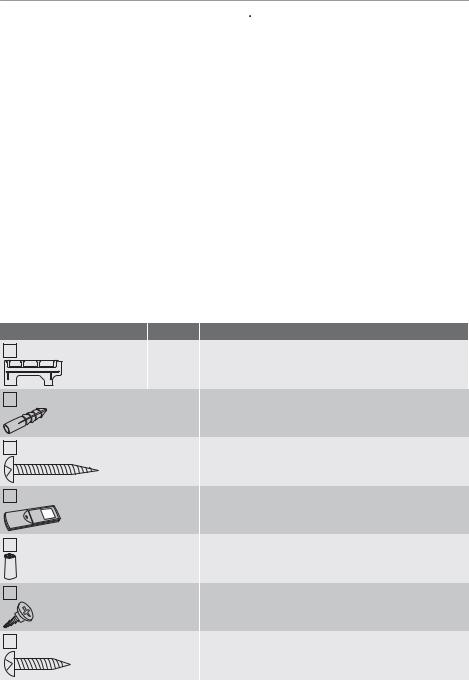
Accessories
 Caution! This room Heatpump uses new refrigerant R410A.
1.Keep any open ends of pipes be sealed with a cap, etc. until connected with the equipment.
2.Exercise great care when performing piping installation so as water, dust, etc. will not enter into the piping and equipment.
3.Pipes connected to the indoor and outdoor units must be used new. (This Heatpump using R410A incurs pressure higher compared with R22, it is necessary to choose adequate materials.)
4.Use only R410A refrigerant when charging additional refrigerant to the equipment. Never add lubricating oil to the equipment in any case.
5.In order to prevent any other refrigerant from being charged accidentally, the service port diameter of the 3-way valve has been changed. (1/2” UNF screw)
|
Items |
Q'ty |
Application |
1 |
Mounting plate |
1 |
To mount the indoor unit on the wall. |
2 |
Wall plug |
8 |
To fix the mounting plate with the long screws. To fix the |
|
|
|
remote control with the special screw. |
3 |
Long screw |
7 |
To fix the mounting plate with the wall plugs. |
4 |
Remote control |
1 |
To control remotely. |
5 |
Dry battery |
2 |
For the remote control. AAA batteries. |
6 |
Special screw |
1 |
To mount the remote control on the wall. |
7 |
Short screw |
1 |
To fix the CORD HOLDER. |

electrolux 3
|
Items |
Q'ty |
Application |
8 |
Cord holder |
1 |
To secure the electrical cable. |
9 |
Manuals |
1 |
Installation manual |
INSTALL
OPER
|
1 |
Operation manual |
10 Air purifying filter |
2 |
To remove dust and tobacco smoke from the air. |
|
|
|
Notes on locations
Important! Keep the following points in mind and get the customer's approval.
Indoor unit
1.Keep the air outlet clear of any obstacle so that outgoing air flows smoothly in the entire room.
2.Make a drain hose hole for easy drainage.
3.Provide sufficient space on both sides and above the unit.
4.The air filters should be easily taken in and out.
5.Keep TV set, radio and the like 1 m or more away from the unit and the remote control.
6.Keep the air inlet clear of obstacles that could block incoming air.
7.The remote control may not function properly in a room equipped with an electronic simultaneous-start or rapidstart fluorescent lighting.
8.Select a location that does not cause loud operation noise and extreme vibrations.
Outdoor unit
1.Place the outdoor unit on a stable base.
2.Provided sufficient space around the unit. It should also be well ventilated.
3.The unit should not be exposed to strong wind nor splashed with rain water.
4.Water drain from the unit should be let out without problem. Lay a drain hose if required. In cold regions, installation of the drain pipe is not advisable as freezing could result.
5.Keep TV set, radio and the like 1 m or more away from the unit.
6.Avoid locations exposed to machine oil vapor, salty air (facing the seashore, for example), hot spring vapor sulfur gas,
etc. Such location can cause breakdown.
7.Also, avoid locations exposed to muddy water (along a road, for example) or where the unit can be tampered with.
8.Select a location where the outgoing air or operating noise cannot annoy others.
9.Install the unit on a stable base not to allow louder noise.
10.Keep the air outlet opening free of any obstacle. This could affect the performance of the unit and create loud noises.
Piping
1.Piping length should be 1m or more in order to decrease vibration propagated from the outdoor unit.
2.If piping length exceeds 10m, add 20g of refrigerant per 1m.
3.When the outdoor unit is placed at a higher level than the indoor units, provide a trap near the hose’s lead-in port.
1
A
B
B
2
3
A)Max. piping length 15m
B)Max. level difference 7m
1Indoor unit
2Outdoor unit
3Trap

4 electrolux
Locations of indoor and outdoor unit
min. 50
min. 50 |
min. 50 |
|
|
|
min. 70 |
|
4 |
min. 50
min. 100 |
min. 200 |
min. 200
Length unit: mm
Provide as much installation space as possible for efficient functioning.
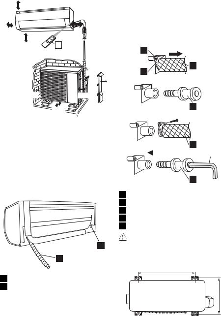
Notes on drain hose
 The drain hose can be connected at either side of the indoor unit.
The unit has been shipped with the drain hose connected at left (viewed from the back of the unit) and the drain cap applied at right.
2
1
4. Reconnect the drain hose to the right and insert the drain cap to the left.
Fully insert the drain hose until it stops and use the screw that was previously removed in STEP (1) to secure the hose holder to the drain pan.
Insert a hexagon socket screw key (4mm diagonal) into the drain cap, and press it fully.
1 1 2
3
2
3 
4
 4
4
3
|
4 |
5 |
|
||
|
4
1Screw
2Hose holder
3Drain hose
4Drain cap
5Hexagon socket screw key
 Caution! After replacing, make sure that both the drain hose and drain cap are firmly inserted.
Outdoor unit mounting screw holes
1 |
Drain hose |
540 |
2 |
Drain cap |
|
Reposition the drain hose and drain cap as |
|
|
required. |
|
|
1. |
Remove the fixed screw in the hose |
|
|
holder at the end of the drain hose. |
|
2. |
Hold the end of the drain hose, and pull it |
|
|
out. |
|
3. |
Pull out the drain cap. |
|
299

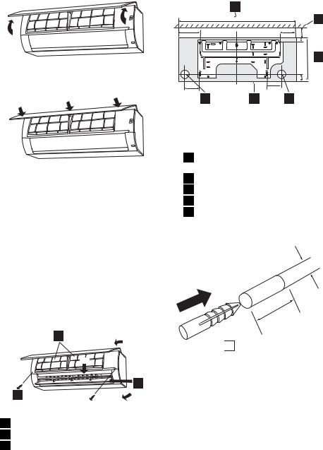
Opening/closing open panel
To open, hold the left and right bottom corners of the panel and lift it up.
electrolux 5
Placing the mounting plate and making a tube hole
Important! Fix the mounting plate horizontally.
To close, press-fit the arrow-marked points.
Detaching the front panel
For servicing, for example, detach the front panel in the following steps. Be sure to disconnect the power cord from the wall outlet or turn off the circuit breaker.
1.Remove the air filter.
2.Unscrew the 2 screws of the front panel.
3.Open the vertical adjustment louver by hand.
4.Remove the front panel.
–Slightly open the lower part of the front panel, and extract the 5 hooks along the upper surface for disassembly.
5.To set the panel back into position, press-fit it at the bottom first and then press its top.
3 4
|
1 |
|
2 |
1 |
3 |
2 |
|
1Screw
2Vertical adjustment louver
3Air filter
5
860 |
|
|
|
4 |
175 |
|
125 |
|
|
I |
|
J |
|
|
|
|
30 |
E |
|
|
|
E |
|
|
D |
|
|
|
|
I |
|
J |
292 |
5 |
D |
|
|
||
F |
|
A |
|
|
|
|
45 |
|
|
115 |
|
108 |
|
|
|
|
|
|
|
F |
|
|
|
|
1 |
2 |
A3 |
|
|
1.Referring to the figure above, mark the location for the wall plugs and the tube hole.
Length unit: mm
1Center of wall hole: Leftward piping.
2Outline of indoor unit
3Center of wall hole: Backward piping
4Ceiling
5unit size
2.Drill diameter 6.5mm, depth 32mm holes and fit the wall plug.
6,5 mm
32 mm

 2
2
3.Secure mounting plate and check the stiffness. Refer to figure at right for fixing hole locations on mounting plate. Fix mounting plate to wall at 7 points. Recommended fixing holes are marked in circle around the hole.
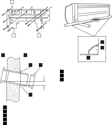
6 electrolux
2
1 |
3 |
4. Drill a piping hole with 70mm diameter concrete drill or a hole saw with a 5mm down ward slant to the outside.
1 2
3 4
5 mm
5
1Indoor
2Outdoor
3Cut with a saw
4Cap (Downward to outdoor)
5Sleeve
5.Set the sleeve and caps.
Setting up the indoor unit
Piping route
For directions 1 and 3, cut out the specific zone without leaving any sharp edge. (Keep the cut-out plate for possible future use.)
3
1 
 2
2
3
 2
2
1
1Cut the plate along notch
2Cut-out
3Notch
Mounting the indoor unit
If the wall is 250 mm or thicker, connect the pipes first.
1.For rear exit piping, pass the auxiliary pipe and the drain hose through the piping hole, and hook the unit onto the mounting plate.
2.Push the unit and apply the bottom hooking points to the mounting plate's support. (Take this step after cabling between the indoor and outdoor units.)
3.Pull the bottom of the unit to check that the unit is fixed in place.
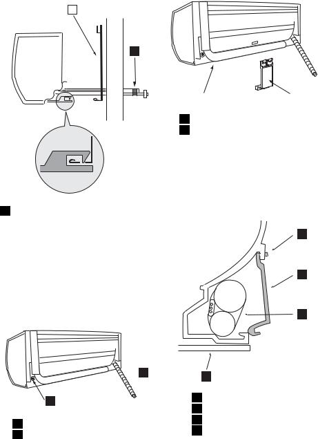
1
1 |
1 Taping
Detaching the unit from the mounting plate
Push the “  “ marks at the bottom of the indoor unit and pull the bottom of the unit. When the hooks are released from the mounting plate, support the bottom of the unit and lift the unit upwards.
Horizontal Piping
1.Reverse the positions of the drain hose and drain cap. Refer to Notes on drain hose.
 2
2
1
1Drain cap
2Drain hose
2.Connect the pipes and coil tape around the pipes and electrical cable.
electrolux 7
1 |
|
2 |
1Unit
2Piping holder
3.Store the pipes within the back cavity of the unit, and secure the pipes by attaching the piping holder. (Refer to steps a) and b) as shown below.)
a)Insert the top of the piping holder into the square opening.
4
3
2
1
1Unit
2Tape
3Piping holder
4Insert
b)Hook the bottom of piping holder to the unit.

8 electrolux
 2
2
1
1Unit
2Hook
4.Coil tape around the drain hose together with the pipes and electrical cable.
5.Hook the unit onto the mounting plate.
Connecting the electrical cable to the indoor unit
1.Process the end of the electrical cable for the indoor side.
–Use a copper cable. (Cross-section area 2mm² or more)
–Use a cable which is not lighter than polychloroprene sheathed flexible cord (design 245 IEC 57).
40mm
8mm 
3
N 1 2
|
1 |
|
8 |
7 |
2 |
|
1Earth wire
2Electrical cable
3Terminal board
4.Fix the cable with the accompanying cord holder and the short screw.
5.Close the open panel.
Connecting the drain hose
Indoor unit
1.Connect a drain hose.
2.Tape over the connecting part.
ø 18mm
1
1 Drain hose
2.Open the open panel by about 70°.
3.Connect the electrical cable.
–Be very careful not to confuse the terminal connections. Wrong cabling may damage the internal control circuit.
–The markings on the indoor unit’s terminal board must match with those of the outdoor unit.
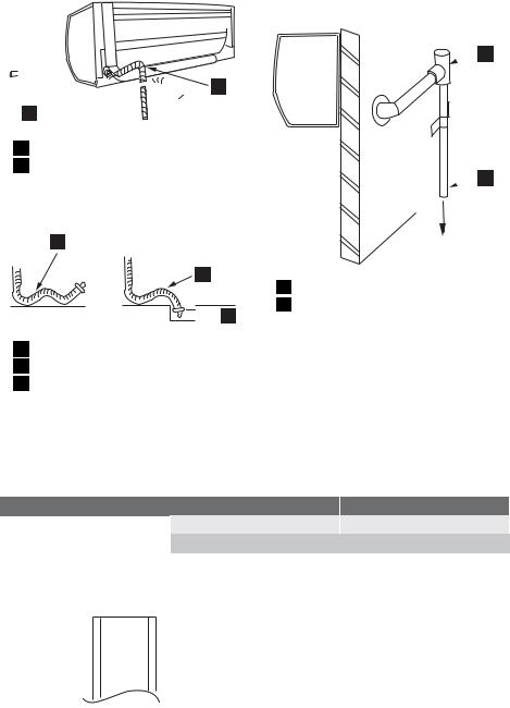
•Be sure to lay the drain hose downward for smooth drainflow.

 2 1
2 1 
1No trap allowed
2Not to rise
•Be careful not to allow the drain hose to rise, form a trap or leave its end in water, as shown below.
electrolux 9
on a high-rise building, for example. For this purpose, employ a "T tube joint" (PVCmade, commercially available) halfway in the hose.

 2
2
 1
1
1
2


 3
3
1Not running wavy
2No trap allowed
3Not left in water
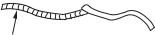
•Coil thermal insulation around a drain hose extension, if running in the room.
•It is recommended to add an "intermediate air vent" when the drain hose is extended horizontally, or an "anti-back-flow air vent" when the hose is exposed to high winds
Flare nut tightening torque
|
Tube size |
|
Liquid side |
|
1/4" |
Gas side |
|
3/8" |
|
|
|
Flaring the pipe end
1.Cutting with a pipe cutter Cut at a right angle.
1To drainage pit
2Air vent (T tube joint)
Connecting the refrigerant pipes
•Use pipes with thickness 0.8mm.
•Connect the pipes for the indoor unit first and then for the outdoor unit.
•Bend the pipes carefully as not to damage them.
•Do not over tighten the tubes; it may be deformed or damaged.
Use a torque wrench, when possible. See the table below for the flare nut tightening torque.
Torque
16±2N·m (1.6±0.2kgf·m)
38±4N·m (3.8±0.4kgf·m)
Allow no cuttings in the pipe.
3.Putting in the flare nut
4.Flaring
Flare processing dimensions (A) differ according to the type of flare tool.
2. Deburring
10 electrolux
A |
R410A tool: 0-0.5mm
Conventional tool: 1.0-1.5mm
5.Checking
To be flared perfectly circular. Flare nut not missing.
Connecting the pipes
1.Tighten the flare nuts by hand for the first 3-4 turns.
2.Use two wrenches to tighten up the pipes.
2
1Flare body
2Flare nut
3.Wind coating tape around refrigerant pipes together with drain hose and electrical cable for general.
1Coating tape
–Lay the drain hose below the pipes.
–The thermal insulation should cover both the GAS and LIQUID pipes as
shown below. As insulation, use polyethylene foam 6 mm or thicker.
2
5
3
4
1Gas
2Insulation
3Liquid
4Drain hose
5Electrical cable
OK |
OK |
OK |
1 |
1 |
1 |
2 |
2 |
2 |
3 |
3 |
3 |
1Gas
2Liquid
3Insulation
Air removal
Use an adapter for preventing vacuum pump oil from flowing back to the gauge manifold hose.
ON/OFF operation of the vacuum pump should be made by the adapter switch.
1.Remove both valve shaft caps of the 2 and 3-way valves.
2.Remove the service port cap of the 3- way valve.
3.Connect the gauge manifold hose to the service port and the vacuum pump.
Be sure that the hose end to be connected to the service port has a valve core pusher.
4.Open the gauge manifold valve and operate the vacuum pump for 10-15 minutes.
Make sure the compound gauge reads -76cmHg.
5.Close the gauge manifold valve.
6.Turn off the vacuum pump.
7.Fully open the 2-way valve with hexagon socket screw key. (diagonally 4 mm) Turn all the way up to contact.

8.Fully open the 3-way valve with hexagon socket screw key. Turn all the way up to contact.
9.Disconnect the gauge manifold hose from the service port.
10.Replace the service port cap and both
valve shaft caps tightly.
•Use a gauge manifold and hoses exclusive for R410A.
•After air removal, check the tube connections for gas leak using a leakage detector or soapy water. Regarding leakage detector, use high-sensitivity type designed specially for R410A.
|
11 |
|
3 |
|
2 |
7 |
3 |
1 |
9 |
|
1 |
|
10 |
|
1 |
|
10 |
electrolux 11
1Valve shaft cap
2Hexagon socket screw key
32 - way valve
4Service port cap
5Vacuum pump
6Vacuum pump adapter
7Gauge manifold
8Compound gauge
9Valve shaft cap
103 - way valve
11Indoor unit
10 |
7 |
|
8 |
||
8 |
||
Lo Hi |
||
9 |
4 |
1 |
10 |
5 |
|
||
|
|
|
|
|
6 |
4 |
|
5 4 |
|
|
|
|
|
6 |
Valve shaft cap tightening torque
|
Pipe size |
|
Width |
Torque |
|
Liquid side |
|
1/4" |
|
22mm |
24±3N·m (2.4 |
|
|
|
|
|
±0.3kgf·m) |
Gas side |
|
3/8" |
|
22mm |
24±3N·m (2.4 |
|
|
|
|
|
±0.3kgf·m) |
Service port cap tightening torque
Torque
11±1N·m (1.1±0.1kgf·m)
Pump down
(Pump down is adopted in the case of unit removal for re-installation, abandonment, repair etc.)
Pump down is to collect the refrigerant into the outdoor unit by control of the 2 and 3- way valves and the compressor.
1.Stop the Heatpump operation.
2.Remove both valve shaft caps of the 2 and 3-way valves.
3.Run the Heatpump at cooling test run mode (Refer to TEST RUN). If pump down is performed at normal cooling operation, the protection system may engage and stop the operation.
4.After 5~10 minutes, fully close the 2-way valve by turning the hexagon socket screw key clockwise.
5.After 2~3 minutes, immediately close the 3-way valve fully.

12 electrolux
6.Stop the test run operation.
7.Replace both valve shaft caps tightly.
8.Disconnect both refrigerant pipes.
•Do not perform the pump down when at heating mode. The refrigerant will not be collected.
Connecting the electrical cable to the outdoor unit
1.Process the end of the electrical cable for the outdoor unit.
40mm
8mm 
2.Remove the control box cover.
3.Remove the cable holder and connect the cable.
Be sure that the terminal connections are as specified.
4.Fix the electrical cable sheath with the cable holder and the screw.
5.Double-check that the cable is securely in place.
6.Place the control box cover back in the reverse order.
1 |
N 1 2 |
|
2 |
||
|
3
6
4
1Earth wire
2Terminal board
3Cable holder
4Electrical cable
5Control box cover
6Screw
Caution!
•Use the specified electrical cable. Make sure the cable is secured in place and that the terminals are free of any excess force from the cable. Otherwise overheating or fire may result.
•Dress the cable so that the control box cover, the cord holder and cable holder are not loose. Double-check that the cover is tight in position. Otherwise overheating, fire or electric shock may result.
•Be sure to put the cable leads deep into the terminal board and tighten up the screws. Poor contact can cause overheating or fire, or malfunction.
Power cabling
Prepare a dedicated power supply circuit. For the connections, see below.
Supply power |
220-240V, single-phase |
Circuit breaker |
10A (EXH09HX1WI) |
|
15A (EXH12HX1WI) |
|
|
1A
2B
3 C

|
|
electrolux 13 |
|
|
|
|
Power supply cable |
Power supply |
A |
Blue |
Neutral |
B |
Brown |
Live |
C |
Green/yellow-striped |
Ground |
|
|
|
•The appliance shall be installed in accordance with national wiring regulations. Wrong connection can cause overheating or fire.
•Fit a disconnect switch, having a contact separation of at least 3mm in all poles, to the electricity power line.
Earth leakage breaker
•Provide an earth leakage breaker in order to protect against electric shock in case of leak.
•Use the current-activated, high-sensitivity, high-speed type breaker with a rated sensitivity current of below 30 mA and an operating time of below 0.1 second.
Hanging the remote control
1.Fit the special screw to the wall with the wall plug.
2.Hang the remote control to the screw head.
1.Open the cover.
2.Insert the batteries.
3.Close the cover.
–If after battery replacement the control fails to function, take out the batteries. Wait for more than 30 seconds and put them in again.
Test run
1.Open the open panel to see the control section.
2.Start the operation with the remote control.
3.Press the “AUX” button on the unit for 5 seconds or more.
2 6
1
1 Remote control rear side
Loading the batteries
Slide the cover in the direction of the arrow.
A beep sound is heard and the OPERATION lamp starts flashing. Now the system is in the cooling test run mode.
4. To put the system in the heating test run mode, start the cooling operation and select the heating mode on the remote control.
14 electrolux
5.Make sure the system runs well, and press the AUX button again to stop the operation.
Explanation to Customer
•Explain to the customer how to use and maintain the system, referring to the operation manual.
•Ask the customer to carefully read the operation manual.
•When the system has been set up, hand the installation manual to the customer.
Important! Important points to explain
Whipping sound :
•The system adjusts itself, by expansion or shrinkage, according to great temperature fluctuations.
Running liquid sound :
•The refrigerant runs in the system, generating such sound. (For details, refer to the accompanying operation manual.)
electrolux 15
Varmepumpe
Vigtigt Læs denne vejledning grundigt. Den sikrer, at installationen forløber glat og uden problemer.
Tilbehør
 Bemærk Denne varmepumpe til rumopvarmning anvender et nyt kølemiddel, R410A.
1.Evt. åbne slangeender skal proppes til, indtil de sluttes til enheden.
2.Vær meget omhyggelig, når rørføringen udføres, så der ikke kommer vand, støv og lign. ind i rør og anlæg.
3.Der skal anvendes nye rør til tilslutningerne på udeog indeenheden. (Da varmepumpen bruger R410A som kølemiddel, udsættes den for højere driftstryk end med R22, og det skal der tages højde for ved materialevalget).
4.Brug kun R410A-kølemiddel, når der efterfyldes kølemiddel på anlægget. Smør aldrig anlægget med smøreolie.
5.Diameteren på 3-vejsventilens driftsindgang er ændret for at sikre, at der ikke utilsigtet kan påfyldes et andet kølemiddel. (1/2" UNF-skrue)
|
Betegnelse |
Antal |
Anvendelse |
1 |
Monteringsplade |
1 |
Til vægmontering af indeenhed. |
2 |
Rawlplug |
8 |
Til fastgørelse af monteringspladen med de lange skruer. |
|
|
|
Til fastgørelse af fjernbetjening med specialskrue. |
3 |
Lang skrue |
7 |
Til fastgørelse af monteringspladen med rawlpluggene. |
4 |
Fjernbetjening |
1 |
Til fjernstyret betjening. |
5 |
Batteri |
2 |
Til fjernbetjeningen. AAA-batterier. |
6 |
Specialskrue |
1 |
Til vægmontering af fjernbetjening. |
7 Kort skrue |
1 |
Til fastgørelse af KABELKLEMME. |
|

16 electrolux |
|
||
|
|
Betegnelse |
Antal |
8 |
Kabelklemme |
1 |
|
9 |
Vejledninger |
1 |
|
INSTALL |
OPER |
|
|
|
|
|
1 |
10 Luftrensningsfilter |
2 |
||
Anvendelse
Til fastgørelse af netkablet.
Installationsvejledning
Betjeningsvejledning
Til at fjerne støv og tobak fra luften.
Bemærkninger om placering
Vigtigt Husk på følgende, og spørg kunden om lov.
Indeenhed
1.Hold luftudblæsningen fri for forhindringer, så den udgående luft uhindret kan sendes rundt i hele rummet.
2.Lav et hul til afløbsslange, for nem aftapning.
3.Sørg for, at der er god plads på begge sider og over enheden.
4.Det skal være let at komme til at tage luftfiltrene ud og sætte dem i.
5.Hold tv-apparat, radio og lign. mindst 1 meter fra enheden og fjernbetjeningen.
6.Sørg for, at der ikke står noget i vejen for luftindsugningen, så indtaget blokeres.
7.Hvis der findes lamper med fluorescerende lys i rummet, virker fjernbetjeningen muligvis ikke, som den skal.
8.Vælg en placering, der ikke giver kraftige støjgener og vibrationer under drift.
Udeenhed
1.Sæt udeenheden på et stabilt underlag.
2.Sørg for god plads rundt om enheden. Der skal også være god lufttilførsel.
3.Enheden må ikke udsættes for kraftig blæst eller sprøjt fra regnvand.
4.Det skal være let at komme til enhedens vandafløb. Læg evt. en afløbsslange. I kolde egne frarådes det at installere et afløbsrør, da det vil kunne fryse til.
5.Hold en afstand på mindst 1 meter til tvapparat, radio og lign.
6.Undgå placeringer, hvor enheden udsættes for dampe fra motorolie, saltholdig luft (f.eks. ved kysten), svovlgas fra varme kilder og lign. På sådanne placeringer kan enheden bryde sammen.
7.Undgå også placeringer, hvor enheden udsættes for mudret vand (f.eks. langs en vej), eller hvor nogen kan komme til at pille ved den.
8.Vælg en placering, hvor udblæsningsluft eller driftsstøj ikke kan genere naboer.
9.Installer enheden på et stabilt underlag, der ikke forstærker støjen.
10.Hold luftudblæsningen fri for forhindringer af enhver art. De vil kunne påvirke enhedens ydelse og give kraftig støj.
Rørføring
1.Rørlængden skal mindst være 1 meter for at mindske de vibrationer, der forplanter sig fra udeenheden.
2.Hvis rørlængden er over 10 meter, tilsættes 20 g kølemiddel pr. løbende meter.
3.Hvis udeenheden placeres højere end indeenhederne, skal der være en vandlås tæt ved slangens indføringsåbning.
1
A
B
B
2
3
A)Maks. rørlængde: 15 meter
B)Maks. niveauforskel: 7 meter
1Indeenhed
2Udeenhed
3Vandlås
Placering af indeog udeenhed
min. 50
min. 50 |
min. 50 |
|
|
|
min. 70 |
|
4 |
min. 50
min. 100 |
min. 200 |
min. 200
Længdeenhed: mm
Sørg for at give installationen så meget plads som muligt for at sikre effektiv funktion.
Bemærkninger om afløbsslange
 Afløbsslangen kan tilsluttes på begge sider af indeenheden.
Enheden leveres med afløbsslangen tilsluttet til venstre (set fra enhedens bagside) og med afløbsproppen til højre.
2
1
1Afløbsslange
2Afløbsprop
Omplacér afløbsslange og afløbsprop, hvis det er nødvendigt.
1.Fjern den faste skrue i slangeholderen i enden af afløbsslangen.
2.Hold fast i enden af afløbsslangen, og træk den ud.
3.Træk afløbsproppen ud.
electrolux 17
4. Tilslut afløbsslangen til højre, og sæt afløbsproppen i på venstre side.
Sæt afløbsslangen så langt ind, som den kan komme, og spænd slangeholderen fast på bundkarret med den skrue, der blev taget ud under TRIN (1).
Sæt en unbrakonøgle (4 mm diameter) i afløbsproppen, og tryk den helt ind.
1 1 2
3
2
3 
4
 4
4
3
|
4 |
5 |
|
||
|
4
1Skrue
2Slangeholder
3Afløbsslange
4Afløbsprop
5Unbrakonøgle
Bemærk Kontroller efter montering af afløbsslange og afløbsprop, at de sidder helt fast.
Skruehuller til montering af udeenhed
540
299
18 electrolux
Åbne/lukke adgangspanel
Panelet åbnes ved at holde i nederste højre og venstre hjørne og løfte det op.
Placering af monteringsplade og hul til rørføring
Vigtigt Fastgør monteringspladen vandret.
Panelet lukkes ved at trykke det på plads på de steder, der er markeret med pile.
|
5 |
|
|
860 |
|
175 |
|
125 |
I |
|
J |
|
|
E |
|
D |
|
I |
|
J |
|
D |
|
F |
|
A |
115 |
|
108 |
|
|
|
F |
|
|
1 |
2 |
A3 |
45 30
 E
E 
292
4
5
Aftagning af frontpanel
Til service og lign. afmonteres frontpanelet som beskrevet nedenfor. Sørg for at tage stikket ud af kontakten eller afbryde på ejendommens el-tavle.
1.Fjern luftfilteret.
2.Skru de 2 skruer i frontpanelet ud.
3.Åbn med hånden spjældet til lodret justering.
4.Fjern frontpanelet.
–Åbn frontpanelets nederste kant lidt, og træk de 5 kroge langs overkanten ud, så panelet kan tages af.
5.Panelet monteres igen ved at først at trykke det på plads langs underkanten og derefter trykke foroven.
3 4
|
1 |
|
2 |
1 |
3 |
2 |
|
1Skrue
2Spjæld til lodret justering
3Luftfilter
1.Markér placeringen af rawlpluggene og hullet til rørføringen som vist på ovenstående tegning.
Længdeenhed: mm
1Centrum, hul i væg: Rørføring til venstre.
2Omrids, indeenhed
3Centrum, hul i væg: Rørføring bagud
4Maks.
5enhedens størrelse
2.Bordiameter 6,5 mm, 32 mm dybe huller. Sæt rawlplugs i.
6,5 mm
32 mm

 2
2
3.Spænd monteringspladen fast, og mærk efter, at den ikke giver sig. Hullernes placering på monteringspladen er vist på tegningen til højre. Fastgør monteringspladen i væggen i 7 punkter. Anbefalede monteringshuller er markeret med en cirkel om hullet.

electrolux 19
2
1 |
3 |
4. Bor hul til rørgennemføring med et 70 mm murbor eller en hulsav, med 5 mm fald mod ydersiden.
1 2
3 4
5 mm
5
1Inde
2Ude
3Skær til med sav
4Prop (med fald udefter)
5Muffe
5.Påsæt muffe og propper.
Opsætning af indeenhed
Rørføring
Til retningerne 1 og 3 udskæres det pågældende område uden skarpe kanter. (Gem det afskårne stykke til evt. senere brug).
3
1 
 2
2
3
 2
2
1
1Skær pladen langs rillen
2Afskæring
3Rille
Montering af indeenhed
Hvis væggen er 250 mm tyk eller derover, tilsluttes rørene først.
1.Ved afgang bagtil sættes forlængerrøret og afløbsslangen gennem rørgennemføringen, og enheden hægtes på monteringspladen.
2.Tryk på enheden, og sæt den fast på monteringspladen ved at klemme den ind over krogene nederst på monteringspladen. (Det gøres først, når ledningsføringen mellem indeog udeenhed er færdig).
3.Træk i underkanten af enheden for at sikre, at den sidder helt fast.
20 electrolux
1
1 |
1 Bevikling
Afmontering af enhed fra monteringspladen
Tryk på "  "-markeringerne nederst på indeenheden, og træk i enhedens underkant. Når krogene slipper monteringspladen, understøttes enheden nedefra og løftes opad.
Vandret rørføring
1.Byt om på placeringen af afløbsslange og afløbsprop. Se under Bemærkninger til afløbsslange.
 2
2
1
1Afløbsprop
2Afløbsslange
2.Tilslut rørene, og vikl tape rundt om rørene og elkablet.
1 |
|
2 |
1Enhed
2Rørholder
3.Gem rørene i hulrummet bag i enheden, og sæt dem fast med rørholderen. (Se trin
a)og b) nedenfor).
a)Sæt toppen af rørholderen ind i det firkantede hul.
4
3
2
1
1Enhed
2Tape
3Rørholder
4Hul
b)Hægt nederste ende i underkanten af enheden.
 Loading...