


STEP 570 X
STEP 600 X
GB |
Instructions for use |
|
Please read and save these |
|
instructions. |
D |
Gebrauchsanleitung |
|
Bitte lesen und aufbewahren. |
F |
Instruction d’utilisation |
|
Prière de lire et de conserver. |
I |
Istruzioni d’uso |
|
Si prega di leggere le istruzioni e |
|
di conservarle. |
E |
Instrucciones de uso |
|
Lea y conserve estas |
|
instrucciones por favor. |
P |
Instruções de serviço |
|
Por favor leia e conserve em seu |
|
poder. |
NL |
Gebruiksaanwijzing |
B
A
III |
II |
I
0
DK Brugsanvisning
Vær venlight at læse og opbevare.
S Bruksanvisning
Var god läs och tag tillvara dessa instruktioner.
FIN Käyttöohje
Lue ja säilytö
TR Kullanøm kølavuzu
Lütfen okuyun ve saklayin
RUS Инструкция по использованию
Пожалуйста, прочтите и сохраните настоящую инструкцию
Lees en let goed op deze adviezen.

You are demanding and expect to purchase quality goods – quality offered by Atlas Copco. We have built a durable and reliable electric power tool for you.
Please read the instructions for use before first operation so you can handle your power tool effectively and safely. We are sure that buying an AEG Electric Power Tool from Atlas Copco was the right choice!
Technical Data |
|
|
STEP 570 X |
STEP 600 X |
|
|||
|
|
Cutting depth max. in: |
|
|
|
|
|
|
|
|
Soft– wood . . . . . . . . . . . . . . |
. . . . . . 95 |
mm . . . . . . . |
. . . . . 110 |
mm |
|
|
|
|
Hard–wood . . . . . . . . . . . . . . |
. . . . . 65 |
mm . . . . . . . |
. . . . . . 70 |
mm |
|
|
|
|
Steel . . . . . . . . . . . . . . . . . . . . |
. . . . . . . 8 |
mm . . . . . . . |
. . . . . . . 8 |
mm |
|
|
|
|
Aluminium . . . . . . . . . . . . . . . |
. . . . . 10 |
mm . . . . . . . |
. . . . . . 15 |
mm |
|
|
|
|
Nominal power . . . . . . . . . . . . . |
. . . . 570 |
W . . . . . . . . |
. . . . . 600 |
W |
|
|
|
|
Stroke rate under no-load . . . |
450–3000 min-1 . . . . . |
450–3000 min-1 |
|
|||
|
|
Lengths of stroke . . . . . . . . . . . |
. . . . . 19 |
mm . . . . . . . |
. . . . . . 19 |
mm |
|
|
|
|
Bevel cuts up to . . . . . . . . . . . . |
. . . . . 45o |
. . . . . . . . . . |
. . . . . 45o |
|
|
|
|
|
Weight . . . . . . . . . . . . . . . . . . . . |
. . . . . 2,1 |
kg . . . . . . . . |
. . . . . 2,1 |
kg |
|
|
|
|
|
|
|
||||
Advice for your |
J Please pay attention to the safety instructions in the attached leaflet! |
|
||||||
safety |
J Dust that arises when working on material containing asbestos or stonework |
|
||||||
|
|
|||||||
|
|
containing crystalline silicic acid is harmful to the health. Please follow accident |
|
|||||
|
|
prevention regulations. |
|
|
|
|
|
|
|
J Appliances used at many different locations including open air must be connected |
|
||||||
|
|
via a current surge preventing switch. |
|
|
|
|
|
|
|
J Always use the protective shields on the machine. |
|
|
|
|
|||
|
J Always disconnect the plug from the socket before carrying out any work on the |
|
||||||
|
|
machine. |
|
|
|
|
|
|
|
J Always wear goggles when using the machine. It is recommended to wear gloves, |
|
||||||
|
|
sturdy non slipping shoes and apron. |
|
|
|
|
|
|
|
J Sawdust and splinters must not be removed while the machine is running. |
|
||||||
|
J Do not pierce the motor housing as this could damage the double insulation (use |
|
||||||
|
|
adhesives). |
|
|
|
|
|
|
|
J Keep mains lead clear from working range of the machine. Always lead the cable |
|
||||||
|
|
away behind you. |
|
|
|
|
|
|
|
J Only plug-in when machine is switched off. |
|
|
|
|
|
||
|
J Dust that arises when working on wood or using the tool on industrial material can be |
|
||||||
|
|
dangerous to health. In this case connect the tool to a suitable suction device. |
|
|||||
|
J Do not use cracked or distorted saw blades. |
|
|
|
|
|||
|
|
|
|
|||||
Measured sound |
|
Typically the A-weighted sound pressure level of the tool is 82 dB (A).The noise |
|
|||||
value |
|
level when working can exceed 85 dB (A). Wear ear protectors! Measured values |
|
|||||
|
|
determined according to EN 50 144. |
|
|
|
|
|
|
Measured |
|
Typically the weighted acceleration is 4 m/s2. |
|
|
|
|
||
vibration value |
|
Measured values determined according to EN 50 144. |
|
|
|
|
||
Use |
|
This jig saw can cut wood, plastic and metal; it can cut straight lines, bevels, curves, |
|
|||||
|
|
and internal cut-outs. |
|
|
|
|
|
|
|
|
Do not use this product in another way as stated for normal use. |
|
|
|
|||
Mains |
|
|
|
|
||||
|
Connect only to a single-phase AC current supply and only to the mains voltage |
|
||||||
connection |
|
specified on the rating plate. Connection to sockets without earth protection is |
|
|||||
|
|
possible as the appliance features protective insulation to DIN 57 740/ VDE 0740 |
|
|||||
|
|
and CEE 20. Radio suppression complies with the European standard EN 55014. |
|
|||||
|
|
When fitting the plug, make sure that the brown (live) wire of this appliance is |
|
|||||
|
|
connected to the plug terminal marked L or coloured red, and the blue (neutral) wire |
|
|||||
|
|
of this appliance is connected to the plug terminal marked N or coloured black. |
|
|||||
|
|
Under no circumstances must the wires of this appliance be connected to the earth |
|
|||||
|
|
terminal of the plug marked either E, with the earth symbol or coloured green or |
|
|||||
|
|
green/yellow. |
|
|
|
|
|
|
|
|
|
|
|
|
|
|
|
ENGLISH |
1 |
|
|
|
STEP 570 X, STEP 600 X |
|
||

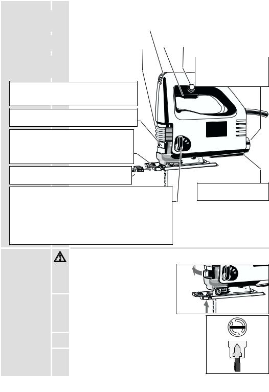
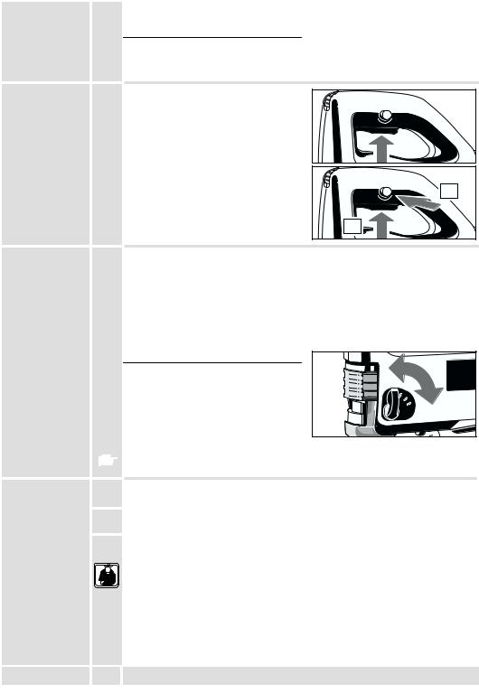
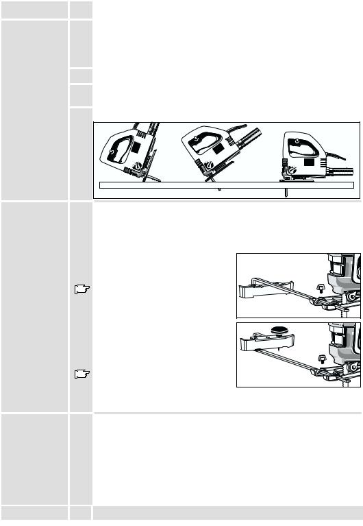
Brief description
The on-off switch is shaped in such a way that it can be used from the forward or the
rear holding position.
The stroke-rate (= movements per minute of the saw blade) can be infinitely varied by means of the
adjustment wheel. The on-off switch can be fixed in the ”On”- position for continuous operation
by means of the locking button.
Transparent cover for optimum sawdust removal.
The sawdust blower removes sawdust ahead of |
|
Integrated suction channel |
|
for connection to a |
|
the cut – very practical when sawing along a line. |
|
|
B |
vacuum-cleaner. |
|
|
|
|
|
A |
|
The vibration damper permits quieter running by means of a counterweight on the plunger.
The saw blade can be changed in seconds by using the tension lever.
III |
II |
I
0
The base plate can be tilted to both sides by 45o for bevel cuts.
The anti-splintering device almost entirely prevents the edge of the wood from splintering.
|
|
|
|
Integrated tool storage for |
The built-in pendulum stroke improves the cutting performance. |
|
|
spare blade. |
|
The pendulum stroke of the saw blade means it is only pressed |
|
|
|
|
|
|
|
||
against the material on the reverse stroke (working stroke) and |
|
|
|
|
lifted off the material on the forward stroke. |
|
Modifications: Text, diagrams and data are |
||
Result: better extraction of sawdust, lower friction –> higher cutting |
|
|||
|
correct at the time of printing. In the interest of |
|||
performance. |
|
continuous improvement of our products, |
||
The pendulum stroke can be adjusted by the pendulum stroke |
|
technical specifications are subject to alteration |
||
control and thus adapted to different kinds of material. |
|
without prior notice. |
||
|
|
|
||
|
|
|
|
|
|
|
|
|
|
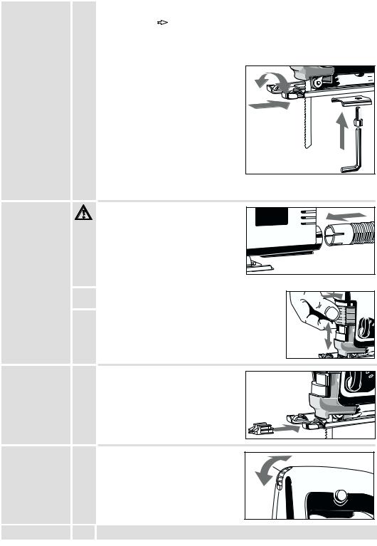
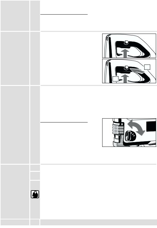
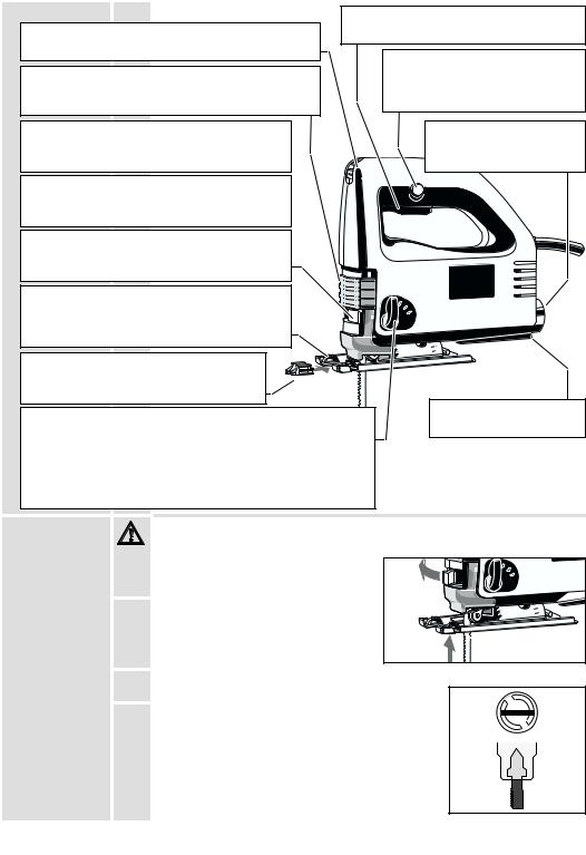
Inserting the saw-blade
Always disconnect the plug from the socket before carrying out any work on the machine.
1. |
Push the tension lever as far as it will go, |
I |
0 |
||
|
as shown in the illustration. |
|
2. |
Fit the saw blade into the groove in the |
|
|
support roller and push it firmly into the |
|
|
plunger as far as it will go; the lug of the |
|
|
saw blade must be in the plunger (see |
|
|
illustration). |
|
3. |
Release the tension lever and the saw |
|
|
blade is gripped automatically. |
|
4. Check that the saw blade fits firmly (wear protective gloves!); the slot in the plunger must always be at an angle to the saw blade (see illustration below).
 When fixing the saw blade it might be in a slightly sloping position.
When first cutting it will adjust automatically.
ENGLISH |
2 |
STEP 570 X, STEP 600 X |
Adjusting the |
The base plate can be tilted or moved backward or forward. |
|
base plate |
Setting an angle |
For angle cuts and bevels. |
|
||
|
Loosen the fixing screw, pull the base plate out of the mounting, set it at the |
|
|
required angle (15o, 30o, 45o), push it back into the mounting and tighten the fixing |
|
|
screw again. Angles other than 45o can be set by not pushing the base plate back |
|
|
into the mounting. |
|
|
The angle can be read off the scale. |
|
|
For very exact angle cuts it is |
|
|
recommended to make a test cut. |
|
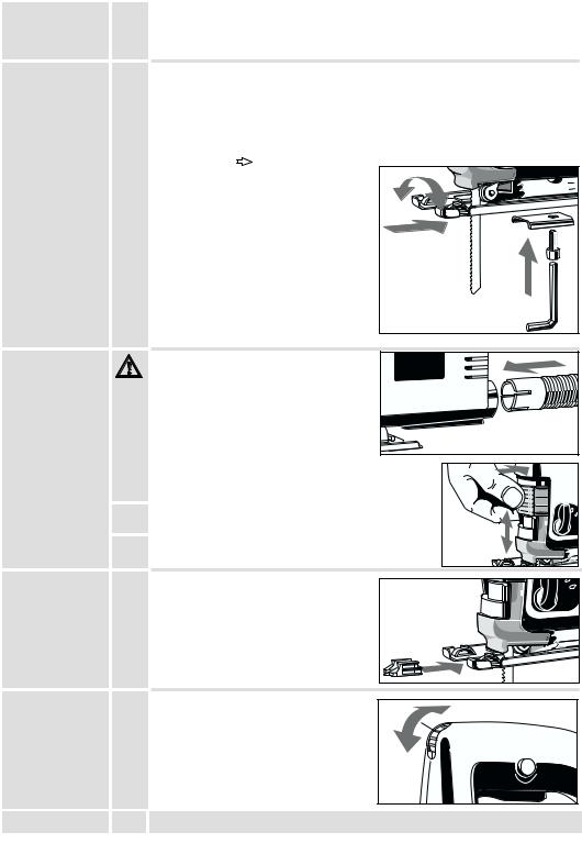
Moving the base plate  For plunge cuts or cuts in corners.
Loosen the fixing screw, push the base plate to the rear and tighten the fixing screw again. The base plate in this position is fixed at the 0o setting.
Moving back  For cutting a hole with a short saw blade and sawing near the
edge. Take the fixing screw out, push the base
plate to the rear and screw the fixing screw tightly into the rear hole.
In this position the base plate can also be off-set in longitudinal direction.
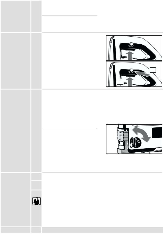
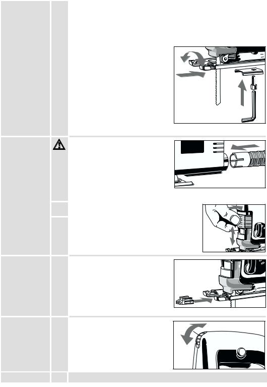
Sawdust removal |
Only operate the machine with suitable |
|
sawdust removal. |
The integrated suction channel has the standardized internal diameter of 30 mm. Use the suction hose (Id. No.
4932 3304 12) from our range of accessories to connect it to a household vacuum cleaner or to an wet-and-dry vacuum cleaner.
1. |
Push in and turn the suction hose into the suction |
|
|
|
channel until it fits firmly. |
|
|
2. |
Push the transparent cover downwards to ensure |
III |
II |
|
optimum sawdust removal. |
|
|
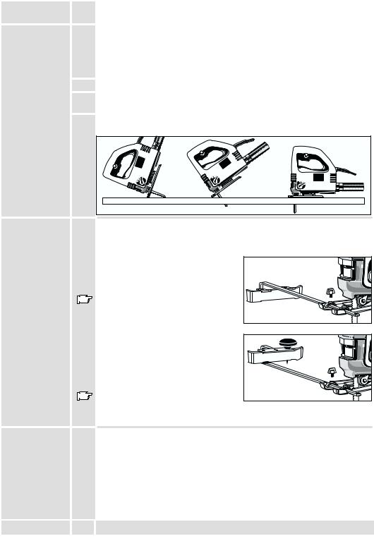
Anti–splintering |
The anti-splintering device almost entirely |
|
|
|
|||
device |
prevents the edge of the wood from |
|
|
|
|||
|
splintering. |
||
Place the anti-splintering device as shown in the illustration with the smooth side downwards and flush with the base plate
(this is only possible with the base plate in the forward position).
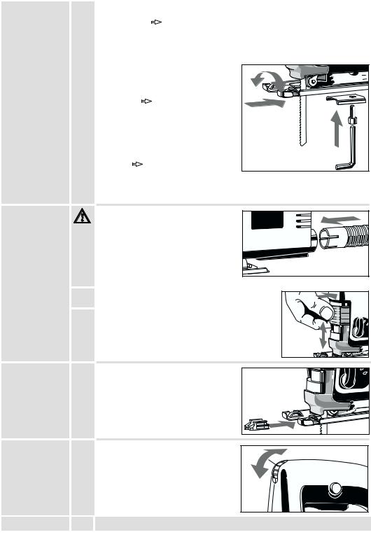
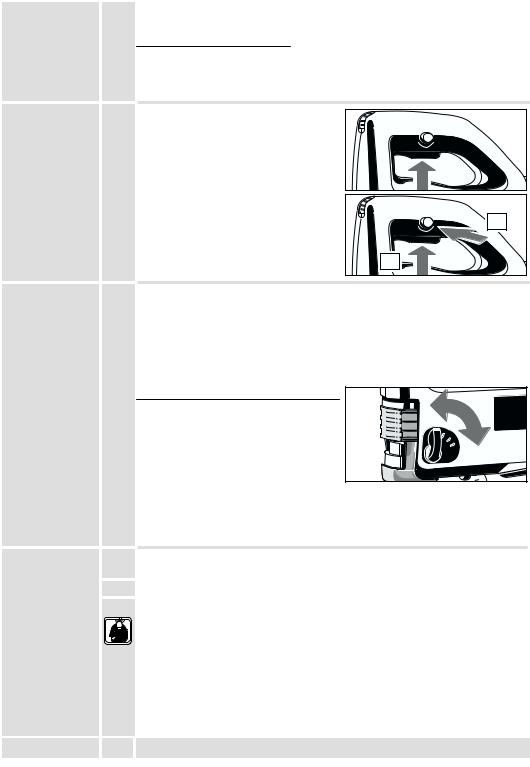
Adjusting the |
|
The stroke-rate (= movements per minute |
|
stroke rate |
|
of the saw blade) can be infinitely varied |
|
|
|
by means of the adjustment wheel. |
B |
|
|
The letters A to G are printed on the speed |
A |
|
|
|
|
|
|
control, meaning: |
|
|
|
A = lowest stroke rate |
|
|
|
G = highest stroke rate |
|
ENGLISH |
3 |
|
STEP 570 X, STEP 600 X |
On-/off switch
Adjusting the pendulum stroke
Advice for operation
Hints
ENGLISH
The stroke rate appropriate to the material being worked on can be taken from the following table, and the corresponding letter shown on the setting wheel.
Material |
Stroke rate |
|
Wood |
G |
|
Steel |
D-E |
|
Aluminium |
D-E |
|
Rubber |
A-C |
|
Intermittent use |
B |
|
Switching on: Press On-/off switch |
A |
|
Switching off: Release On-/off switch |
|
|
Continuous use |
|
Switching on: Press the On-/off switch and |
|
then the locking button, after that release |
|
on-off switch. |
|
Switching off: Press the On-/off switch and |
B |
A |
|
then release. |
2 |
|
|
|
1 |
By adjusting the pendulum action the cutting depth of the saw blade teeth is increased or decreased. As a rule of thumb:
Soft material |
Large pendulum stroke |
Hard material |
Small or no pendulum stroke |
Clean cut surface |
No pendulum stroke |
The appropriate degree of pendulum effect can be taken from the following chart and compared with the marking at the pendulum stroke lever.
Material |
Degree of swing action |
|
|
Wood |
I - III |
|
|
Plastic |
I |
III |
II |
Aluminium |
0 - I |
|
I |
|
0 |
||
Steel |
0 |
|
|
Ceramics |
0 |
|
|
Rubber |
0 |
|
|
The stroke rate shown in the chart is only a suggestion for your general guidance!
 The stroke rate can be set on the stroke rate control even while the motor is running.
1. Set the stroke and pendulum stroke according to the material to be cut.
2.Position the machine with the front part of the base plate on the material, and switch on.
3.Press the machine downwards onto the material and guide it along the cutting line.
Do not press down too hard on the piece you are cutting. Light pressure on the saw blade is sufficient to achieve the optimum rate of sawing.
When cutting along a score line, use the marking on the anti-splintering device as an optical guide.
To obtain a perfectly straight cut, clamp a strip of wood as a guide along the material or use the parallel guide (accessory).
For cutting at an angle, or cutting a bevel, adjust the base plate.
For sawing close to the edge, set the base plate at its rearmost position.
4 |
STEP 570 X, STEP 600 X |
Sawing sheet |
To avoid vibration, clamp metal sheets onto a wooden base. |
metal |
To saw metal, use cooling agents along the cutting line (oil, white spirit). |
Plunge cuts |
|
Plunge cuts without pre-drilling a hole are possible with soft materials (wood, light |
|
|
building materials for walls). Harder materials (metals) must first be drilled with a hole |
|
corresponding to the size of the saw blade. |
|
Move the base plate to the rearmost setting in order to obtain the best possible |
|
cutting angle for starting the cut.(see section ”Adjusting the base plate”) |
1.Set the pendulum stroke at the pendulum stroke control to “0”.
2.Without switching the machine on, place it with the front edge of the base plate on the cutting point.
3.Switch the machine on and carefully lower the saw blade already running into the material.
|
0 |
I |
I |
0 |
I |
III |
|
|
|
II |
|
|
|
III |
III |
|
|
|
II |
|
|
|
I |
0
Parallel guide |
|
Using the parallel guide or circle cutting, parallel cuts of 0–200 mm, circular cuts of |
and circle cutting |
|
100–400 mm are possible. Use cross-cut saw blades. |
guide |
|
*Not included in standard equipment, available as an accessory. |
(Accessory*) |
|
|
Assembly of |
|
Push the parallel guide, with the contact |
parallel guide |
|
surface facing downwards, through the |
|
|
lugs in the base plate and fasten it in |
|
|
position with the capstand–headed screw. |
|
|
For cutting from the left or from the right, |
|
|
push the parallel guide in from the |
|
|
appropriate side. |
Cutting a circle |
|
Push the parallel guide, with the contact |
|
|
surface facing upwards, through the lugs |
|
|
in the base plate and fasten it in position |
|
|
with the capstand–headed screw. |
|
|
Tighten the centre point into the parallel |
|
|
guide from the top. |
|
|
Ensure that the saw blade and the circle |
|
|
centre point form one single line. |
|
|
Further accessories with part numbers are shown in our catalogues. |
Maintenance |
|
In order to guarantee constant readiness for operation, the machine should be |
|
|
checked for worn carbon brushes at one of the AEG after–sales service agencies. |
|
|
Use only AEG accessories and spare parts. Should components need to be |
|
|
replaced which have not been described, please contact one of our AEG service |
|
|
agents (see our list of guarantee/service addresses). |
|
|
If needed, an exploded view of the tool can be ordered. Please state the ten–digit |
|
|
No. as well as the machine type printed on the label and order the drawing at your |
|
|
local service agents or directly at: Atlas Copco Electric Tools GmbH, Postfach 320, |
|
|
D–71361 Winnenden. |
ENGLISH |
5 |
STEP 570 X, STEP 600 X |

|
|
Sie sind anspruchsvoll und erwarten Qualität, die Ihnen Atlas Copco bietet. |
|
|||||
|
|
Für Sie haben wir ein haltbares und möglichst sicheres Elektrowerkzeug gebaut. |
|
|||||
|
|
Bitte lesen Sie vor Inbetriebnahme Ihres Gerätes die Gebrauchsanleitung, um Ihr |
|
|||||
|
|
Elektrowerkzeug effektiv und gefahrlos nutzen zu können. |
|
|
|
|||
|
|
Wir sind sicher, daß Sie mit AEG-Elektrowerkzeugen von Atlas Copco Ihre richtige |
|
|||||
|
|
Wahl getroffen haben. |
|
|
|
|
|
|
|
|
|
|
|
|
|
||
Technische |
|
|
STEP 570 X |
STEP 600 X |
|
|||
Daten |
|
Schnittiefe max. in: |
|
|
|
|
|
|
|
|
Weichholz . . . . . . . . . . . . . . |
. . . . . . 95 |
mm . . . . . . . |
. . . . . 110 |
mm |
|
|
|
|
Hartholz . . . . . . . . . . . . . . . . . |
. . . . . 65 |
mm . . . . . . . |
. . . . . . 70 |
mm |
|
|
|
|
Stahl . . . . . . . . . . . . . . . . . . . . |
. . . . . . . 8 |
mm . . . . . . . |
. . . . . . . 8 |
mm |
|
|
|
|
Aluminium . . . . . . . . . . . . . . . |
. . . . . 10 |
mm . . . . . . . |
. . . . . . 15 |
mm |
|
|
|
|
Nennaufnahme . . . . . . . . . . . . |
. . . . 570 |
W . . . . . . . . |
. . . . . 600 |
W |
|
|
|
|
Leerlaufhubzahl . . . . . . . . . . . |
450–3000 min-1 . . . . . |
450–3000 min-1 |
|
|||
|
|
Hubhöhe . . . . . . . . . . . . . . . . . . |
. . . . . 19 mm . . . . . . . |
. . . . . . 19 mm |
|
|||
|
|
Schrägschnitte bis . . . . . . . . . . |
. . . . . 45o |
. . . . . . . . . . |
. . . . . 45o |
|
|
|
|
|
Gewicht . . . . . . . . . . . . . . . . . . . |
. . . . . 2,1 |
kg . . . . . . . . |
. . . . . 2,1 |
kg |
|
|
|
|
|
|
|
|
|||
Hinweise für |
J |
Sicherheitshinweise der beiliegenden Broschüre beachten! |
|
|
|
|||
Ihre Sicherheit |
J |
Staub der bei der Bearbeitung von asbesthaltigen Materialien und Gestein mit |
|
|||||
|
|
|||||||
|
|
kristalliner Kieselsäure entsteht, ist gesundheitsschädlich. Beachten Sie die |
|
|||||
|
|
Unfallverhütungsvorschriften VBG 119 der Berufsgenossenschaft. |
|
|
|
|||
|
J |
Steckdosen in Außenbereichen müssen mit Fehlerstrom-Schutzschaltern |
|
|||||
|
|
ausgerüstet sein. Das verlangt die Installationsvorschrift für Ihre Elektroanlage. Bitte |
|
|||||
|
|
beachten Sie das bei der Verwendung unseres Gerätes – sprechen Sie mit Ihrem |
|
|||||
|
|
Elektroinstallateur. |
|
|
|
|
|
|
|
J |
Schutzeinrichtung der Maschine unbedingt verwenden. |
|
|
|
|
||
|
J |
Vor allen Arbeiten an der Maschine Stecker aus der Steckdose ziehen. |
|
|||||
|
J |
Beim Arbeiten mit der Maschine stets Schutzbrille tragen. Schutzhandschuhe, festes |
|
|||||
|
|
und rutschsicheres Schuhwerk und Schürze werden empfohlen. |
|
|
|
|||
|
J |
Späne oder Splitter dürfen bei laufender Maschine nicht entfernt werden. |
|
|||||
|
J |
Gehäuse der Maschine nicht anbohren, da sonst die Schutzisolierung unterbrochen |
|
|||||
|
|
wird (Klebeschilder verwenden). |
|
|
|
|
|
|
|
J |
Anschlußkabel stets vom Wirkungsbereich der Maschine fernhalten. Kabel immer |
|
|||||
|
|
nach hinten von der Maschine wegführen. |
|
|
|
|
|
|
|
J |
Maschine nur ausgeschaltet an die Steckdose anschließen. |
|
|
|
|||
|
J |
Bei längerem Bearbeiten von Holz oder bei gewerblichem Einsatz für Materialien, bei |
|
|||||
|
|
denen gesundheitsgefährdende Stäube entstehen, ist das Elektrowerkzeug an eine |
|
|||||
|
|
geeignete externe Absaugvorrichtung anzuschließen. |
|
|
|
|
||
|
J |
Rissige Sägeblätter oder solche, die ihre Form verändert haben, dürfen nicht |
|
|||||
|
|
verwendet werden! |
|
|
|
|
|
|
|
|
|
|
|||||
Geräusch- |
|
Der A-bewertete Schalldruckpegel des Gerätes beträgt typischerweise 82 dB (A).Der |
|
|||||
meßwerte |
|
Geräuschpegel beim Arbeiten kann 85 dB (A) überschreiten. Gehörschutz tragen! |
|
|||||
|
|
Meßwerte ermittelt entsprechend EN 50 144. |
|
|
|
|
||
|
|
|
|
|
|
|||
Vibrations- |
|
Die bewertete Beschleunigung beträgt typischerweise 4 m/s2. |
|
|
|
|||
meßwerte |
|
Meßwerte ermittelt entsprechend EN 50 144. |
|
|
|
|
||
|
|
|
|
|||||
Verwendung |
|
Die Stichsäge sägt Holz, Kunststoff und Metall. Sie schneidet Geraden, Gehrungen, |
|
|||||
|
|
Kurven und Innenausschnitte. |
|
|
|
|
|
|
|
|
Dieses Gerät darf nur wie angegeben bestimmungsgemäß verwendet werden. |
|
|||||
Netzanschluß |
|
|
|
|
||||
|
Nur an Einphasen-Wechselstrom und nur an die auf dem Leistungsschild |
|
||||||
|
|
angegebene Netzspannung anschließen. Anschluß ist auch an Steckdosen ohne |
|
|||||
|
|
Schutzkontakt möglich, da eine Schutzisolierung nach DIN 57 740/ VDE 0740 bzw. |
|
|||||
|
|
CEE 20 vorliegt. Die Funkentstörung entspricht der Europanorm EN 55014. |
|
|||||
|
|
|
|
|
|
|
|
|
DEUTSCH |
6 |
|
|
|
STEP 570 X, STEP 600 X |
|
||

Kurzbeschreibung |
Der Ein-/Ausschalter ist so geformt, daß er in |
||
|
|
||
|
|
vorderer und hinterer Griffposition bedient |
|
Mit dem Stellrad kann die Hubzahl (= Bewegung des |
werden kann. |
||
|
|
||
Sägeblattes pro Minute) stufenlos reguliert werden. |
Für Dauerschaltung kann der |
||
|
|
||
Verschiebbare Klarsichtabdeckung für optimale |
Ein-/Ausschalter am Arretierknopf |
||
festgestellt werden. |
|||
Späneabsaugung. |
|
|
|
Die Späneblasvorrichtung bläst den Schnitt von |
|
Integrierter |
|
|
Absaugkanal zum Anschluß |
||
Spänen frei; sehr praktisch beim Sägen nach |
|
||
B |
einer Späneabsaugung. |
||
Anriß. |
|
|
|
|
A |
|
|
Der Vibrationsausgleich ermöglicht einen |
|
|
|
ruhigeren Lauf durch gegenläufige Gewichte am |
|
|
|
Stößel. |
|
|
|
Blitzschneller Sägeblattwechsel ohne Werkzeug |
|
|
|
mit Spannhebel. |
|
|
|
|
|
III |
II |
Für Schrägschnitte ist die Fußplatte beidseitig |
|
I |
|
|
0 |
||
um 45o verstellbar, für Tauchschnitte und |
|
|
|
randnahes Sägen ist sie nach hinten versetzbar. |
|
|
|
Der Spanreißschutz verhindert weitgehend |
|
|
|
das Absplittern an der Schnittkante bei |
|
|
|
Holzbearbeitung. |
|
|
|
|
|
|
Integrierte Werkzeuggarage |
Die eingebaute Pendelung erhöht die Schnittleistung. |
|
für Zusatzblatt. |
|
Durch die Pendelbewegung des Sägeblattes wird dieses nur beim |
|
||
Rückwärtshub |
(Arbeitshub) gegen das Material gedrückt, beim |
|
|
Vorwärtshub jedoch vom Material abgehoben. Ergebnis: besserer |
|
||
Spanauswurf, geringere Reibung –> höhere Schnittleistung. |
Änderungen: Text, Bild und Daten |
||
entsprechen dem technischen Stand zur Zeit |
|||
Am Pendelschalter kann die Pendelung verstellt und somit den |
des Drucktermins. Änderungen im Sinne der |
||
verschiedenen Materialien angepasst werden. |
Weiterentwicklung unserer Produkte sind |
||
|
|
vorbehalten. |
|
Einsetzen des |
Vor allen Arbeiten an der Maschine Stecker aus der Steckdose ziehen. |
||
Sägeblattes |
|
|
|
1. |
Spannhebel wie in Abbildung gezeigt bis |
I |
0 |
||
|
Anschlag nach außen schwenken. |
|
2. |
Sägeblatt in die Nut der Stützrolle legen |
|
|
und bis zum Anschlag fest in den Stößel |
|
|
einschieben; die Nasen des Sägeblattes |
|
|
müssen vollständig im Stößel eintauchen |
|
|
(siehe Abbildung). |
|
3. |
Spannhebel loslassen – das Sägeblatt |
|
|
wird automatisch gespannt |
|
4. Sägeblatt auf festen Sitz kontrollieren (Schutzhandschuhe tragen!); der Schlitz des Stößels muß schräg zum Sägeblatt stehen (siehe Abbildung).
 Unter Umständen kann das Sägeblatt nach dem Einspannen nicht exakt in Schnittrichtung stehen
(leichte Schräglage).
Beim ersten Anschnitt richtet sich das Sägeblatt jedoch automatisch aus.
DEUTSCH |
7 |
STEP 570 X, STEP 600 X |
Verstellen der |
Die Fußplatte kann schräggestellt, verschoben oder versetzt werden. |
||
Fußplatte |
Schrägstellung |
Gehrungen (Schrägschnitte) |
|
|
|||
|
Hierzu Feststellschraube lösen, Fußplatte aus der Rasterung ziehen, im |
||
|
gewünschten Winkel (15o, 30o, 45o) einrasten lassen und Feststellschraube |
||
|
wieder festziehen. |
|
|
|
Andere Winkel bis 45o sind außerhalb der Rasterung einstellbar. |
||
|
Der Winkel kann an Skala abgelesen |
||
|
werden. |
|
|
|
Für sehr genaue Schrägschnitte, zuvor |
||
|
einen Probeschnitt durchführen. |
||
|
Verschieben |
Tauchschnitte mit |
|
|
langem Sägeblatt |
|
|
|
Hierzu Feststellschraube lösen, Fußplatte |
||
|
nach hinten schieben und |
||
|
Feststellschraube wieder festziehen. |
||
|
In dieser Position ist die Fußplatte in |
||
|
0o-Stellung fixiert. |
|
|
|
Versetzen |
Tauchschnitte mit kurzem |
|
|
Sägeblatt und randnahes Sägen |
||
|
Hierzu Feststellschraube herausschrauben, Fußplatte nach hinten versetzen und |
||
|
Feststellschraube in der hinteren Bohrung festziehen. |
||
|
Die Fußplatte ist auch in dieser Position in Längsrichtung verschiebbar. |
||
Späneabsaugung |
Maschine nur mit einer geeigneten |
||
|
Späneabsaugung betreiben. |
||
Der integrierte Absaugkanal hat den genormten Innen-ø von 30 mm. Zum Anschluß an einen
Haushaltsstaubsauger oder einen AEG
Naßund Trockensauger den Saugschlauch (Id.Nr. 4932 3304 12) aus dem Zubehörprogramm verwenden.
1. |
Saugschlauch drehend in den Absaugkanal stecken |
|
|
|
bis er festsitzt. |
|
|
2. |
Klarsichtabdeckung nach unten schieben, somit ist |
III |
II |
|
eine optimale Staubabsaugung gegeben. |
|
|
Spanreißschutz |
Der Spanreißschutz verhindert weitgehend |
|
|
|
|||
|
das Absplittern an der Schnittkante bei |
|
|
|
|
||
|
Holzbearbeitung. |
||
Den Spanreißschutz wie in Abb. mit der glatten Seite nach unten bündig auf die Fußplatte stecken (nur in der vorderen Fußplattenstellung möglich).
Einstellen der |
|
Mit dem Stellrad kann die Hubzahl |
|
Hubzahl |
|
(= Bewegung des Sägeblattes pro Minute) |
|
|
|
stufenlos reguliert werden. |
B |
|
|
Auf dem Stellrad sind die Buchstaben |
A |
|
|
|
|
|
|
A ... G aufgedruckt; hierbei gilt: |
|
|
|
A = kleinste Hubzahl |
|
|
|
G = größte Hubzahl |
|
DEUTSCH |
8 |
|
STEP 570 X, STEP 600 X |
Ein-/Ausschalten
Einstellen der Pendelung
Arbeitshinweise
Tips
DEUTSCH
Die für das zu bearbeitende Material geeignete Hubzahl der nachfolgenden Tabelle entnehmen und den entsprechenden Buchstaben auf dem Stellrad einstellen.
Material Hubzahl
Holz |
G |
|
Stahl |
D-E |
|
Alu |
D-E |
|
Gummi |
A-C |
|
Momentschaltung |
B |
|
Einschalten: Ein-/Ausschalter drücken. |
A |
|
Ausschalten: Ein-/Ausschalter loslassen. |
|
|
Dauerschaltung |
|
Einschalten: Ein-/Ausschalter drücken und |
|
dann Arretierknopf drücken, |
|
Ein-/Ausschalter loslassen. |
|
Ausschalten: Ein-/Ausschalter drücken |
B |
A |
|
und loslassen. |
2 |
|
|
|
1 |
Beim Einstellen der Pendelung wird der Eingriff der Sägeblattzähne in das Material vergrößert bzw. verkleinert. Als Faustregel gilt:
Weiche Materialien |
große Pendelung |
Harte Materialien |
kleine Pendelung bzw. keine Pendelung |
Saubere Schnittoberfläche |
keine Pendelung |
Die geeignete Pendelung der nachfolgenden Tabelle entnehmen und am Pendelschalter einstellen.
Material |
Pendelstufe |
|
|
Holz |
I - III |
|
|
Kunststoff |
I |
III |
II |
Alu |
0 - I |
|
I |
|
0 |
||
Stahl |
0 |
|
|
Keramik |
0 |
|
|
Gummi |
0 |
|
|
Die in der Tabelle vorgeschlagenen
Pendelstufen sind nur Anhaltswerte.
 Das Einstellen der Pendelung am Pendelschalter läßt sich auch bei laufender Maschine vornehmen.
1. Hubzahl und Pendelung entsprechend dem zu bearbeitenden Material einstellen
2. Maschine mit dem vorderen Teil der Fußplatte auf das Material aufsetzen und einschalten.
3. Die Maschine von oben auf das Material drücken und entlang der Schnittlinie führen.
Nicht zuviel Schnittdruck geben. Ein leichter Druck auf das Sägeblatt genügt um einen optimalen Sägefortschritt zu erzielen.
Bei Sägen nach Anriß die Markierung im Spanreißschutz als Orientierungshilfe verwenden.
Für exakt gerade Schnitte, eine Leiste als Anschlag auf das Material klemmen oder Parallelanschlag (Zubehör) verwenden.
Für Gehrungsschnitte (Schrägschnitte) die Fußplatte verstellen.
Für randnahes Sägen die Fußplatte in die hinterste Stellung versetzen.
9 |
STEP 570 X, STEP 600 X |
Sägen von |
Um ein Mitfedern zu vermeiden, Bleche auf einer Holzunterlage festspannen. Beim |
Blechen |
Metallsägen entlang der Schnittlinie Kühlmittel (Öl, Petroleum) auftragen. |
Herstellen |
|
Tauchsägen ist nur in weicheren Materialien (Holz, Leichtbaustoffe für Wände) |
|
von Innenaus- |
möglich, bei härteren Materialien (Metalle) muß eine dem Sägeblatt entsprechend |
schnitten |
große Bohrung angebracht werden. |
|
Um einen günstigen Schnittwinkel zum Einstechen zu erhalten, die Fußplatte in die |
|
hinterste Stellung versetzen.(siehe Kap. ”Verstellen der Fußplatte”) |
1.Pendelung am Pendelschalter auf “0” stellen.
2.Maschine ausgeschaltet mit der vorderen Kante der Fußplatte auf die Schnittstelle aufsetzen.
3.Maschine einschalten und Sägeblatt vorsichtig sägend in das Material eintauchen.
|
0 |
I |
I |
0 |
I |
III |
|
|
|
II |
|
|
|
III |
III |
|
|
|
II |
|
|
|
I |
0
Parallelanschlag |
|
Mit Hilfe des Parallelanschlags mit Kreisführung sind Parallelschnitte von 0 - 200 mm |
mit Kreisführung |
|
und Kreisschnitte von 100 - 400 mm möglich. |
(Zubehör*) |
|
Geschränkte Sägeblätter verwenden. |
|
|
* Im Lieferumfang nicht enthalten, empfohlene Ergänzung aus dem |
|
|
Zubehörprogramm. |
Verwendung als |
|
Den Parallelanschlag mit der |
Parallelanschlag |
|
Anschlagfläche nach unten durch die |
|
|
Laschen in der Fußplatte schieben und mit |
|
|
der Knebelschraube befestigen |
|
|
Für links bzw. rechts angeschlagene |
|
|
Schnitte den Parallelanschlag von der |
|
|
entsprechenden Seite einschieben. |
Verwendung als |
|
Den Parallelanschlag mit der |
Kreisführung |
|
Anschlagfläche nach oben durch die |
|
|
Laschen in der Fußplatte schieben und |
|
|
mit der Knebelschraube befestigen. |
|
|
Die Kreisführung von oben in den |
|
|
Parallelanschlag einschrauben. |
|
|
Darauf achten, daß Sägeblatt und |
|
|
Kreisführung eine Linie bilden. |
|
|
Weiteres Zubehör mit den Bestellnummern ersehen Sie bitte aus unseren Katalogen. |
Wartung |
|
Um eine ständige Betriebsbereitschaft zu gewährleisten, sollte die Maschine einmal |
|
|
jährlich auf abgenutzte Kohlebürsten in einem AEG-Kundendienststützpunkt |
|
|
untersucht werden. |
|
|
Nur AEG Zubehör und Ersatzteile verwenden. Bauteile, deren Austausch nicht |
|
|
beschrieben wurde, bei einer AEG Kundendienststelle auswechseln lassen |
|
|
(Broschüre Garantie/Kundendienstadressen beachten). |
|
|
Bei Bedarf kann eine Explosionszeichnung des Gerätes unter Angabe der |
|
|
Maschinen Type und der zehnstelligen Nummer auf dem Leistungsschild bei Ihrer |
|
|
Kundendienststelle oder direkt bei Atlas Copco Electric Tools GmbH, Postfach 320, |
|
|
D–71361 Winnenden angefordert werden. |
DEUTSCH |
10 |
STEP 570 X, STEP 600 X |

Vous avez des exigences et vous voulez de la qualité – une qualité que vous offre Atlas Copco. Nous avons mis au point pour vous un outil électrique de longue durée vous offrant un maximum de sécurité. Avant la mise en service de votre appareil, veuillez lire attentivement le mode d’emploi afin d’en tirer le plus d’efficacité et d’éviter tout risque de danger.
Nous sommes convaincus qu’avec les outils électriques Atlas Copco vous avec fait le choix qu’il fallait.
Caractéristiques |
|
|
STEP 570 X |
STEP 600 X |
||
techniques |
|
Profondeur de coupe max.: |
|
|
|
|
|
|
Bois tendre . . . . . . . . . . . . . . |
. . . . . . 95 |
mm . . . . . . . . . . . |
. 110 |
mm |
|
|
Bois . . . . . . . . . . . . . . . . . . . . . |
. . . . . 65 |
mm . . . . . . . . . . . . |
. 70 |
mm |
|
|
Acier . . . . . . . . . . . . . . . . . . . . |
. . . . . . . 8 |
mm . . . . . . . . . . . . |
. . 8 |
mm |
|
|
Aluminium . . . . . . . . . . . . . . . . |
. . . . . 10 |
mm . . . . . . . . . . . . |
. 15 |
mm |
|
|
Puissance absorbée . . . . . . . . |
. . . . 570 |
W . . . . . . . . . . . . . |
600 |
W |
|
|
Nombre de courses à vide . . |
450–3000 |
min-1 . . . . . 450–3000 |
min-1 |
|
|
|
Hauteur de la course . . . . . . . . |
. . . . . 19 |
mm . . . . . . . . . . . . |
. 19 |
mm |
|
|
Coupe de biais jusqu’à . . . . . . |
. . . . . 45o |
. . . . . . . . . . . . . . . |
45o |
|
|
|
Poids . . . . . . . . . . . . . . . . . . . . . |
. . . . . 2,1 |
kg . . . . . . . . . . . . . |
2,1 |
kg |
|
|
|
||||
Conseils de |
J Respecter les instructions de sécurité se trouvant dans le prospectus ci-joint. |
|||||
sécurité |
J La poussière qui se dégage lors de l’usinage des matériaux contenant de l’amiante |
|||||
|
||||||
|
|
et des pierres contenant de l’acide silicique cristallin porte atteinte à la santé. |
||||
JLes prises de courant se trouvant à l’extérieur doivent être équipées de disjoncteurs de protection, répondant ainsi à la prescription de mise en place de votre installation
électrique. Veuillez, d’une part, en tenir compte lors de l’utilisation de notre appareil et d’autre part, en parler à votre électricien.
JIl est absolument impératif d’utiliser le dispositif protecteur de la machine.
JAvant tous travaux sur la machine extraire la fiche de la prise de courant.
JToujours porter des lunettes protectrices lorsqu’on travaille avec la machine. Des gants de sécurité et un masque de protection sont recommandés.
JNe jamais enlever les copeaux ni les éclats lorsque la machine est en marche.
JNe pas percer le carter de la machine; ceci pourrait entraîner une détérioration de l’isolation de protection (utiliser des autocollants).
JLe câble d’alimentation doit toujours se trouver en dehors du champ d’action de la machine. Toujours maintenir le câble d’alimentation à l’arrière de la machine.
JNe raccorder la machine au réseau que si l’interrupteur est en position arrêt.
JLors de travaux de ponçage de longue durée, sur du bois ou autres matériaux dégageant de la poussière nocive pour la santé, la machine doit être raccordée à un appareil d’aspiration.
JNe pas utiliser de lames de scie fissurées ou déformées.
Mesure de bruit |
|
La mesure réelle (A) du niveau de bruit de l’outil est 82 dB (A).Le niveau du briut en |
|
|
|
|
fonctionement peut dépasser 85 dB (A). Toujours porter des casques protecteurs! |
|
|
|
|
Valeurs de mesures obtenues conformément à la norme européenne 50 144. |
|
|
|
|
|
|
|
Valeur de |
|
L’accélération réelle mesurée est 4 m/s2. |
|
|
vibration |
|
Valeurs de mesures obtenues conformément à la norme européenne 50 144. |
|
|
mesurée |
|
|
|
|
|
|
|
|
|
Utilisation |
|
La scie sauteuse coupe le bois, la matière synthétique et le métal. Elle permet les |
|
|
|
|
coupes droites, de biais, de courbes et de découpes intérieures. |
|
|
|
|
Comme déjà indiqué, cette machine n’est conçue que pour une utilisation normale. |
|
|
Branchement |
|
|
|
|
|
Nos machines fonctionnent uniquement sur courant alternatif monophasé. S’assurer |
|
||
secteur |
|
que la tension du réseau correspond effectivement à celle indiquée sur la plaque |
|
|
|
|
signalétique de la machine. Le branchement sur une prise de courant sans mise à |
|
|
|
|
terre est possible du fait de la double isolation selon normes DIN 57 740/VDE 0740 |
|
|
|
|
et CEE 20. Antiparasitage selon normes européennes EN 55014. |
|
|
|
|
|
|
|
FRANÇAIS |
11 |
STEP 570 X, STEP 600 X |
|
|
Description |
|
|
La forme de l’interrupteur de marche/arrêt |
|||||
|
Le bouton de réglage permet de régler sans à–coups le |
|
|
est telle, qu’il peut être utilisé en position |
||||
|
nombre de courses (nombre de mouvements effectués |
|
|
avant ou arrière de la poignée. |
||||
|
par la lame de scie en une minute). |
|
|
|
|
|
|
|
|
|
|
|
|
|
|||
|
|
|
|
|
|
|
|
|
|
Capot transparent décalable, prévu pour l’aspiration |
|
|
|
|
En marche continue, l’interrupteur |
||
|
|
|
|
|
de marche/arrêt peut être maintenu |
|||
|
optimale des copeaux. |
|
|
|
|
|||
|
|
|
|
|
en position au moyen de blocage. |
|||
|
|
|
|
|||||
|
|
|
|
|
|
|
||
|
|
|
|
|
|
|
|
|
|
|
|
|
|
|
|
|
|
|
|
|
|
|
|
|
|
|
|
Le dispositif d’aspiration des copeaux dégage la |
|
|
|
|
|
|
Canal d’aspiration intégré |
|
coupe, ce qui est particulièrement appréciable lors |
|
|
|
|
|
|
|
|
|
|
|
|
|
|
pour le raccordement d’un |
|
|
du sciage devant être effectué selon un tracé. |
|
|
|
|
|
|
|
|
|
|
|
|
B |
|
dispositif d’aspiration des |
|
|
|
|
|
|
|
|
|
|
|
|
|
|
|
A |
|
|
copeaux. |
|
|
|
|
|
|
|
|
|
La compensation des vibrations se traduit par une coupe très calme grâce aux contrepoids antagonistes au niveau du coulisseau.
Changement ultra-rapide de la lame de scie sans avoir recours à un outil, grâce au levier de serrage.
Afin de permettre la réalisation d’une coupe de |
I |
||
biais, la semelle doit être inclinée des deux côtés |
III II |
||
0 |
|||
à 45o. Elle doit être décalée vers l’arrière |
|
||
lorsqu’on désire effectuer des coupes en |
|
||
plongée et un sciage à proximité des bords. |
|
||
Le pare-éclats réduit considérablement les éclats |
|
||
sur les bords de coupe lors du sciage du bois. |
|
||
Le mécanisme pendulaire intégré augmente le rendement de |
Logement pour une lame |
||
de scie additionnelle. |
|||
coupe. Du fait de son mouvement pendulaire, la lame de scie |
|||
|
|||
n’est pressée contre le matériau qu’au moment du déplacement |
|
||
vers l’arrière (course de travail) et elle est soulevée du matériau |
|
||
pendant le déplacement vers l’avant. |
Modifications: Les textes, les illustrations et |
||
Résultat: meilleure éjection des copeaux, diminution du frottement |
les données techniques correspondent à la |
||
situation au moment de l’impression. Toutes |
|||
–> augmentation de la performance de coupe. |
|||
modifications techniques sont réservées dans |
|||
Le mouvement pendulaire peut être réglé au moyen du |
le cadre du développement technique |
||
commutateur ce qui permet de l’adapter aux différents matériaux. |
permanent. |
||
|
|||
Mise en place de |
Avant tous travaux sur la machine extraire la fiche de la prise de courant. |
||
la lame de scie |
|
|
|
1. |
|
I |
Faire pivoter le levier de serrage vers |
0 |
|
|
||
|
l’extérieur et jusqu’à concurrence de sa |
|
|
butée, comme l’indique la figure |
|
|
correspondante. |
|
2. |
Placer la lame de scie dans la fente du |
|
|
galet d’appui et l’introduire dans le |
|
|
coulisseau jusqu’à concurrence de sa |
|
|
butée; les deux épaulements de la lame |
|
|
de scie doivent venir en contact avec le |
|
|
collet du coulisseau (voir figure). |
|
3. |
Relâcher le levier de serrage et la lame de |
|
|
scie se trouve serrée automatiquement. |
|
4. |
Vérifier le positionnement correct de la lame de scie |
|
|
(ne pas oublier de porter des gants de protection!). La |
|
|
fente du coulisseau doit se trouver en position inclinée |
|
|
par rapport à la lame de scie (voir figure). |
|
FRANÇAIS |
12 |
STEP 570 X, STEP 600 X |
Réglage de la semelle
Aspiration des copeaux
Pare-éclats
Réglage du nombre de courses
FRANÇAIS
 Après avoir serré la lame de scie, il se peut que cell-ci ne soit pas orientée précisément dans le sens de la coupe (position légèrment en biais).
Pendant la première coupe cependant, la lame de scie s’ajustera automatiquement.
La semelle peut être inclinée, repoussée ou décalée. Inclinaison  coupes inclinées (coupe de biais).
Pour ce faire, desserrer la vis de réglage, sortir la semelle du cran, l’encranter à l’angle souhaité (15o, 30o, 45o) et resserrer la vis de réglage. Les autres angles
sont réglables en dehors de la plage d’encrantement. L’angle peut être lu sur le |
|
cadran. |
|
Pour les coupes de biais précises, exécuter préalablement un coupe d’essai. |
|
Repoussement |
coupes en plongée |
avec longue lame de scie. |
|
Pour ce faire, desserrer la vis de réglage, |
|
repousser la semelle vers l’arrière et |
|
resserrer la vis de réglage. Dans cette |
|
position, la semelle est fixée en position |
|
0o.
Décalage  coupes en plongée avec courte lame de scie et coupes à proximité des bords.
Pour ce faire, desserrer la vis de réglage, décaler la semelle vers l’arrière et serrer la vis de réglage dans le trou arrière. Dans cette position, la semelle est également décalable en sens longitudinal.
N’utiliser la machine qu’en liaison avec un dispositif d’aspiration approprié des copeaux.
Le ø intérieur normalisé du canal |
|
d’aspiration intégré est de 30 mm. |
|
Pour permettre le branchement sur un |
|
aspirateur ménager ou un aspirateur à |
|
sec/liquide Atlas Copco, utiliser le tuyau |
|
d’aspiration AEG (Nº 4932 3304 12) |
|
faisant partie du programme |
|
d’accessoires. |
|
III |
II |
1. Introduire intégralement le tuyau d’aspiration dans le |
|
canal en lui appliquant un mouvement de rotation. |
|
2. Pousser le capot transparent vers le bas, afin d’obtenir |
|
une aspiration optimale de la sciure. |
|
Le pare-éclats réduit considérablement les
éclats sur les bords de coupe lors du sciage du bois.
Introduire le pare-éclats sur la semelle comme le montre la figure, c’est-à- dire côté lisse vers le bas (possible uniquement en position avant de la semelle).
|
Le bouton de réglage permet de régler |
|
|
sans à–coups le nombre de courses |
|
|
(nombre de mouvements effectués par la |
B |
|
lame de scie en une minute). |
A |
|
Le bouton de réglage porte les lettres A ... |
|
|
G qui signifient: |
|
|
A = Nombre de courses le plus faible |
|
|
G = Nombre de courses le plus élevé |
|
13 |
|
STEP 570 X, STEP 600 X |
Mise en marche/arrêt
Réglage du mouvement pendulaire
Conseils pratiques
Conseils
FRANÇAIS
Le régime des courses, approprié au matériau à usiner, est spécifié sur le tableau suivant. Il vous suffit d’ajuster la lettre correspondante sur le bouton de réglage.
Matériau à scier |
Nombre de courses |
|
Bois |
G |
|
Acier |
D-E |
|
Aluminium |
D-E |
|
Caoutchouc |
A-C |
|
Marche momentanée |
B |
|
Mise en marche: appuyer sur l’interrupteur |
A |
|
Marche/Arrêt |
|
|
Arrêt: lâcher l’interrupteur Marche/Arrêt |
|
|
Marche continue |
|
Mise en marche: appuyer d’abord sur |
|
l’interrupteur marche/arrêt puis sur le |
|
bouton de blocage, lâcher l’interrupteur |
B |
A |
|
marche/arrêt. |
2 |
Arrêt: appuyer sur l’interrupteur |
|
marche/arrêt et lâcher. |
|
|
1 |
Lors du réglage du mouvement pendulaire, la pénétration des dents de la lame de scie est augmentée ou diminuée. Règle approximative applicable:
Matériaux tendres |
Grand mouvement pendulaire |
Matériaux durs |
Petit mouvement pendulaire ou pas de |
|
mouvement pendulaire Surface de coupe |
soignée |
Pas de mouvement pendulaire |
Les mouvements pendulaires appropriés sont indiqués sur le tableau ci-dessous et se règlent au moyen du commutateur pendulaire.
Matériau |
Degré pendulaire |
|
|
Bois |
I - III |
|
|
Matière synthétique |
I |
III |
II |
Aluminium |
0 - I |
|
I |
|
0 |
||
Acier |
0 |
|
|
Céramique |
0 |
|
|
Caoutchouc |
0 |
|
|
Les degrés pendulaires proposés sur le 


 tableau ne sont bien entendu que des valeurs indicatives et approximatives!
 Le réglage pendulaire au moyen du commutateur peut tout aussi avoir lieu lorsque la machine est en marche.
1. Régler le nombre de courses et mouvements pendulaires en fonction du matériau à scier.
2. Appliquer la partie avant de la semelle sur le matériau à scier et brancher la machine.
3. Appuyer la machine sur le matériau à scier (pression appliquée du haut) et la guider le long de la ligne de coupe.
Ne pas excercer une pression de coupe excessive. Une pression légère sur la lame de scie est amplement suffisante pour garantir une progression optimale de la scie. Lorsque l’on doit scier selon un tracé, se servir du repère placé sur le pare-éclats afin de faciliter l’orientation.
Afin d’assurer une coupe rectiligne, fixer une barrette sur le matériau pour faire office de butée ou encore, utiliser une butée parallèle (accessoire).
Lorsqu’on doit effectuer des coupes inclinées (coupes de biais), il convient alors de décaler la semelle.
S’il s’agit de scier à proximité des bords, amener la semelle dans la position la plus arrière.
14 |
STEP 570 X, STEP 600 X |
Sciage de tôles |
Afin d’éviter l’effet de ressort, fixer les tôles sur un morceau de bois. Si l’on doit scier |
|
du métal, utiliser un liquide réfrigérant le long de la ligne de coupe (huile, pétrole). |
Réalisation de |
Le sciage en plongée n’est possible que dans des matériaux tendres (bois, |
découpes |
matériaux de construction légers pour les murs). Si les matériaux sont plus durs |
intérieures |
(métaux), une percée plus importante doit être faite au moyen de la lame. |
|
Afin d’obtenir un angle de coupe favorable pour le sciage en plongée, déplacer la |
|
semelle dans sa position la plus arrière.(voir chapitre ”Réglage de la semelle”) |
1.Le mouvement pendulaire doit être amené sur ”0” sur le commutateur sélecteur.
2.Le bord avant de la semelle doit être placé sur le point de coupe, alors que la machine est débranchée.
3.Brancher la machine et introduire la lame prudemment dans le matériau.
|
0 |
I |
I |
0 |
I |
III |
|
|
|
II |
|
|
|
III |
III |
|
|
|
II |
|
|
|
I |
0
Butée parallèle |
|
A l’aide du guide parallèle et circulaire, on peut réaliser des coupes parallèles de 0 - |
avec guidage |
|
200 mm et circulaires de 100 - 400 mm. Utiliser des lames de scie sauteuse |
circulaire |
|
avoyées. |
(accessoire*) |
|
*Ces pièces ne font pas partie de la livraison. Il s’agit là de compléments proposés |
|
|
|
|
|
pour votre machine et énumérés dans le catalogue d’accessoires. |
Utilisation en tant |
|
La face d’arrêt de la butée parallèle doit |
que butée |
|
être introduite (orientée vers le bas) dans |
parallèle |
|
l’éclisse de la semelle et être fixée au |
|
|
moyen de la vis à garret. |
|
|
La butée parallèle doit être introduite du |
|
|
côté correspondant pour permettre les |
|
|
coupes à gauche ou à droite. |
Utilisation en tant |
|
La face d’arrêt de la butée parallèle doit |
que guidage |
|
être introduite (orientée vers le bas) dans |
circulaire |
|
l’éclisse de la semelle et être fixée au |
|
|
moyen de la vis à garret. |
|
|
Visser le guidage circulaire dans la butée |
|
|
parallèle. |
|
|
Veiller à ce que la lame de scie forme une |
|
|
seule ligne avec le guidage circulaire, |
|
|
c’est-à-dire, que cet ensemble soit en |
|
|
alignement. |
|
|
Pour d’autres accessoires, consulter notre catalogue. |
Entretien |
|
Afin de garantir une disponibilité de service permanente, il est recommandé de faire |
|
|
contrôler une fois par an les balais (charbons) auprès d’un service après–vente |
|
|
AEG. |
|
|
N’utiliser que des pièces et accessoires AEG. Pour des pièces dont l’échange n’est |
|
|
pas décrit, s’adresser de préférence aux stations de service après-vente AEG (voir |
|
|
brochure Garantie/Adresses des stations de service après-vente). |
|
|
Si besoin est, une vue éclatée de l’appareil peut être fournie. S’adresser, en |
|
|
indiquant bien le numéro à dix chiffres porté sur la plaque signalétique, à votre |
|
|
station de service après–vente (voir liste jointe) ou directement à Atlas Copco |
|
|
Electric Tools GmbH, B.P. 320, D–71361 Winnenden. |
FRANÇAIS |
15 |
STEP 570 X, STEP 600 X |

La vostra richiesta ed aspettativa è quella di acquistare merce d’elevata qualità - qualità offerta da Atlas Copco.
Noi costruiamo per voi utensili elettrici durevoli e affidabili.
Si prega di leggere attentamente le istruzione al primo utilizzo cosicché si possa utilzzare l’utensile elettrico in modo più sicuro e corretto. Siamo sicuri che acquistare gli utensili elettrici AEG di Atlas Copco sia la scelta migliore.
Dati tecnici |
|
|
STEP 570 X |
STEP 600 X |
||
|
|
Massima profondità di taglio nel: |
|
|
|
|
|
|
Legno tenero . . . . . . . . . |
. . . . . . . . . 95 |
mm . . . . . . . . . . . |
. 110 |
mm |
|
|
Legno . . . . . . . . . . . . . . . |
. . . . . . . . . 65 |
mm . . . . . . . . . . . . |
. 70 |
mm |
|
|
Acciaio . . . . . . . . . . . . . . |
. . . . . . . . . . . 8 |
mm . . . . . . . . . . . . |
. . 8 |
mm |
|
|
Alluminio . . . . . . . . . . . . . |
. . . . . . . . . 10 |
mm . . . . . . . . . . . . |
. 15 |
mm |
|
|
Potenza assorbita . . . . . . |
. . . . . . . . 570 |
W . . . . . . . . . . . . . |
600 |
W |
|
|
Numero di corse a vuoto |
. . . 450–3000 |
min-1 . . . . . 450–3000 |
min-1 |
|
|
|
Altezza corsa . . . . . . . . . |
. . . . . . . . . 19 |
mm . . . . . . . . . . . . |
. 19 |
mm |
|
|
Tagli obliqui fino a . . . . . . |
. . . . . . . . . 45o |
. . . . . . . . . . . . . . . |
45o |
|
|
|
Peso . . . . . . . . . . . . . . . . . |
. . . . . . . . . 2,1 |
kg . . . . . . . . . . . . . |
2,1 |
kg |
|
|
|
||||
Norme di |
J Si prega di leggere con attenzione le istruzioni riguardanti la sicurezza, nel volantino |
|||||
sicurezza |
|
allegato. |
|
|
|
|
JTenere presente che la polvere che si solleva durante la lavorazione di materiali con amianto, pietra silice cristallizzata, é dannosa alla salute. Attenersi sempre alle prescrizioni di sicurezza vigenti in materia.
JGli apparecchi mobili usati all’aperto devono essere collegati interponendo un interruttore di sicurezza per guasti di corrente.
JUsare sempre il dispositivo di protezione dell’apparecchio.
JPrima di effettuare qualsiasi lavoro sulla macchina togliere la spina dalla presa di corrente.
JDurante l’uso dell’apparecchio utilizzare sempre gli occhiali di protezione. Inoltre si consiglia di usare sistemi di protezione per la respirazione e per l’udito, oltre ai guanti di protezione.
JNon rimuovere trucioli o schegge mentre l’utensile è in funzione.
JEvitare di forare la carcassa dell’utensile per non danneggiare l’isolamento.
(Utilizzare placchette adesive).
JTenere sempre lontano il cavo di collegamento dall’area di lavoro dell’attrezzo.
JInserire la spina solo con interruttore su posizione “OFF”.
JPer lunghe lavorazioni nel legno o con altri materiali che producono poveri dannose alla salute, e’ prescritto l’utilizzo sull’utensile dell’aspirazione polvere.
JNon devono essere utilizzate nè lame incrinate nè lame la cui forma abbia subito alterazioni.
Livello di |
|
La misurazione A della pressione del livello sonoro di un utensile di solito deve |
|
|
rumorosità |
|
essere 82 dB (A).Il livello di rumorosità durante le lavorazioni può superare gli |
|
|
|
|
85 dB (A). Utilizzare le protezioni per l’udito! |
|
|
|
|
Valori misurati conformemente alla norma EN 50 144. |
|
|
|
|
|
|
|
Livello di |
|
La misurazione dell’accellerazione di solito è 4 m/s2. |
|
|
vibrazione |
|
Valori misurati conformemente alla norma EN 50 144. |
|
|
Possibilità’ di |
|
Questo seghetto alternativo può essere utilizzato per lavorare legno, materiale |
|
|
utilizzo |
|
sintetico e acciaio: per effettuare tagli diritti e obliqui, curve e per tagli all ’ interno del |
|
|
|
|
materiale. |
|
|
|
|
Utilizzare il prodotto solo per l’uso per cui è previsto. |
|
|
Collegamento |
|
|
|
|
|
Alimentazione dell’utensile: corrente alternata monofase. Importante: la tensione |
|
||
alla rete |
|
della rete deve corrispondere a quella riportata sulla targhetta dell’utensile. Il |
|
|
|
|
collegamento é possibile anche con prese non munite di contatto di protezione: é |
|
|
|
|
previsto infatti un isolamento di protezione conforme a norme DIN 57740/VDE 0740 |
|
|
|
|
(CEE 20). La schermatura contro i radiodisturbi é conforme alla norma |
|
|
|
|
europea EN 55014. |
|
|
|
|
|
|
|
ITALIANO |
16 |
STEP 570 X, STEP 600 X |
|
|
Breve indicazione
Regolazione del numero delle corse (movimento della lama al minuto) tramite apposita rotellina.
Copertura trasparente di protezione della lama che può essere spostata per permettere un’aspirazione perfetta dei trucioli.
Soffiatrucioli per mantenere pulita la linea di taglio, particolarmente utile quando si praticano tagli seguendo una traccia.
Interruttore di grandi dimensioni, comodo da azionare.
Per il funzionamento in continuo, l’interruttore può essere bloccato in posizione attraverso il pulsante di arresto interruttore.
|
Canalina integrata di |
|
aspirazione per attaco |
B |
aspiratrucioli. |
A
Compensazione delle vibrazioni, che permette un funzionamento silenzioso, grazie a pesi contrapposti nella sede di inserimento lama.
Sostituzione velocissima della lama. Grazie alla leva di bloccaggio e sbloccaggio della lama infatti, non si ha la necessità di utilizzare alcun attrezzo.
Piedino inclinabile da entrambi i lati fino a 45o |
III II |
||
I |
|||
per effettuare tagli obliqui, e spostabile |
0 |
||
|
|||
posteriormente per tagliare in prossimità dei |
|
||
bordi e per effettuare tagli ad immersione. |
|
||
Dispositivo di protezione del taglio per evitare |
|
||
che il legno si scheggi in prossimità del taglio |
|
||
durante la lavorazione. |
|
|
|
Movimento oscillatorio della lama per migliorare la qualità del |
Vano alloggiamento lama di |
||
scorta intergrato. |
|||
taglio. Grazie a questo movimento oscillatorio, la lama viene |
|||
|
|||
premuta contro il materiale da lavorare solo nella corsa di ritorno |
|
||
(corsa di lavoro), mentre non lo è nella corsa di andata. Risultato: |
|
||
migliore espulsione dei trucioli, minore attrito –> migliore qualità |
Modifiche: Testo, figure e dati corrispondono |
||
del taglio. L’oscillazione può essere regolata, tramite apposito |
allo standard tecnico aggiornato all’epoca della |
||
stampa. Ci riserviamo pertanto eventuali |
|||
interruttore, a seconda del tipo di materiale. |
|||
modifiche tecniche dovute all’ulteriore sviluppo |
|||
|
|
dei nostri prodotti. |
|
Inserimento |
Prima di effettuare qualsiasi lavoro sulla macchina togliere la spina dalla presa di |
||
della lama |
corrente. |
|
|
1. |
Spostare verso l ’esterno e fino al punto di |
I |
0 |
||
|
arresto la leva di bloccaggio e sbloccaggio |
|
|
della lama, come indicato in figura. |
|
2. |
Posizionare la lama nella scanalatura del |
|
|
rullo di appoggio ed spingerla a fondo |
|
|
nella propria sede. Le sporgenze della |
|
|
lama devono essere introdotte |
|
|
completamente nella sede (si veda figura). |
|
3. Rilasciare la leva, la lama verrà fissata automaticamente.
4. Controllare che la lama sia inserita saldamente ed in maniera coretta (indossate i guanti di prodezione). La fessura della sede della lama deve essere obliqua rispetto alla lama (si veda figura sotto).
 Quando si inserisce una lama, questa potrebbe non essere perfettamente allineata. Nel momento in cui si inizia a lavorare questa automaticamente viene allineata.
ITALIANO |
17 |
STEP 570 X, STEP 600 X |
Regolazione del piedino
Aspirazione trucioli
Protezione taglio
Regolazione del numero delle corse
ITALIANO
Il piedino può essere inclinato, spostato o arretrato.
Posizione inclinata  Tagli obliqui.
Per regolare in piedino in questa posizione, allentare la vite di fissaggio, estrarlo dalla tacca di arresto, posizionarlo con l’angolo di inclinazione necessario
(15o,30o, 45o) e riavvitare a fondo la vite di fissaggio. Altri angoli fino a 45o possono essere fissati al di fuori delle tacche. L’angolo di inclinazione può essere letto sulla scala. Per effettuare tagli obliqui
perfetti, praticare prima un taglio di prova.
Arretrare  Tagli ad immersione con lama lunga.
Allentare la vite di fissaggio, spingere indietro il piedino riavvitare a fondo la vite di fissaggio. In questa posizione il piedino di trova a 0o
Cambiare di posizione  Tagli ad immersione con lama corta e per tagliare lungo i bordi. Rimuovere la vite di fissaggio
spostare indietro il piedino e collocare e riavvitare la vite nell’ultimo foro. Il piedino
anche in questo posizione può essere spostato in senso longitudinale.
Utilizzare l’utensile solo con un dispositivo di aspirazione trucioli idoneo.
La conalina di aspirazione integrata. ha un diametro interno di 30 mm. Ad essa può essere collegato, tramite il tubo di aspirazione (N. 4932 3304 12) un aspiraolvere domestico oppure un aspiratore a secco e a umido della AEG che protrete scegliere nell’ampia gamma di accessori della AEG.
1. |
Infilare e fissare il tubo di aspirazione nella canalina di |
|
|
|
aspirazione integrata . |
|
|
2. |
Spingere verso il basso il riparo trasparente della |
III |
II |
|
lama, alfine di ottenere una perfetta aspirazione. |
|
|
Dispositivo di protezione del taglio per evitare che il legno si scheggi in prossimità del taglio durante la lavorazione.
Inserire il dispositivo di protezione del taglio sul piedino con parte piatta rivolta verso il basso, come mostrato in figura.
(Ciò è possibile solo se il piedino si trova nella posizione avanzata).
|
Regolazione del numero delle corse |
|
|
(movimento della lama al minuto) tramite |
|
|
apposita rotellina. |
B |
|
Sulla rotellina sono impresse le lettere |
A |
|
|
|
|
A....G, si tenga presente che: |
|
|
A = minor numero di corse |
|
|
G = maggior numero di corse |
|
18 |
|
STEP 570 X, STEP 600 X |
Accensione–
Spegnimento
Regolazione del movimento oscillatorio della lama
Istruzioni d’uso
Qualche suggerimento
ITALIANO
Si ricavi dalla tabella seguente il numero di corse più adatto per ogni materiale, e si imposti la lettera corrispondente sull’apposita rotellina di regulazione.
Materiale |
numero corse |
|
Legno |
G |
|
Acciaio |
D–E |
|
Alluminio |
D–E |
|
Gomma |
A–C |
|
Inserimento momentaneo |
B |
|
Accensione: premere l’interruttore. |
A |
|
Fermo: lasciare libero l’interruttore. |
|
|
Funzionamento continuo |
|
Accensione: premere l’interruttore e |
|
successivamente il blocco interruttore, poi |
|
lasciare libero l’interruttore. |
|
Fermo: premere e poi lasciare libero |
B |
A |
|
l’interruttore. |
2 |
|
|
|
1 |
Regolando l’oscillazione, si aumenta o si diminuisce l’incisività dei denti della lama nel materiale.
Materiali dolci: |
oscillazione più ampia |
Materiali duri: |
oscillazione ridotta o nessuna oscillazione |
Linea di taglio più pulita |
nessuna oscillazione |
Si ricavi dalla tabella seguente il tipo di oscillazione più idonea e si imposti l’oscillazione attraverso l’apposito interruttore.
Materiale |
Gradi di oscillazione |
|
|
Legno |
I–III |
|
|
Materiale sintetico |
I |
III |
II |
Alluminio |
0–I |
|
I |
|
0 |
||
Acciaio |
0 |
|
|
Ceramica |
0 |
|
|
Gomma |
0 |
|
|
I livelli di oscillazione riportati in tabella sono da considerarsi come puramente
indicativi.
 L’oscillazione può essere impostata o variata, agendo sull’apposito interruttore anche ad utensile in funzione.
1. Impostare l’oscillazione e il numero delle corse più adatti al tipo di materiale da lavorare.
2.Posizionare l’utensile con la parte anteriore del piedino sul materiale e azionare.
3.Premere l’utensile dall’alto sul materiale e guidarlo lungo la linea di taglio.
Non applicare eccessiva pressione. Una leggera pressione sulla lama è sufficiente per ottenere ottimi risultati.
Se si effettuano dei tagli seguendo una traccia,utilizzare la marcatura sul dispositivo di protezione taglio come riferimento.
Per tagli perfettamente diritti, utilizzare un listello come guida, fissandolo sul materiale oppure utilizzare la guida parallela (accessorio)
Il dispositivo di protezione del taglio evita che il legno si scheggi ai bordi del taglio durante la lavorazione.
Per effettuare tagli in prossimità dei bordi portare il piedino nella posizione più arretrata.
19 |
STEP 570 X, STEP 600 X |
 Loading...