

Page 1

ADOBE® ILLUSTRATOR® CS3
USER GUIDE
Page 2

Copyright
© 2007 Adobe Systems Incorporated. All rights reserved.
Adobe® Illustrator® CS3 User Guide for Windows® and Macintosh
If this guide is distributed with software that includes an end user agreement, this guide, as well as the software described in it, is furnished under license and may be used or
copied only in accordance with the terms of such license. Except as permitted by any such license, no part of this guide may be reproduced, stored in a retrieval system, or trans
mitted, in any form or by any means, electronic, mechanical, recording, or otherwise, without the prior written permission of Adobe Systems Incorporated. Please note that the
content in this guide is protected under copyright law even if it is not distributed with software that includes an end user license agreement.
The content of this guide is furnished for informational use only, is subject to change without notice, and should not be construed as a commitment by Adobe Systems Incorporated. Adobe Systems Incorporated assumes no responsibility or liability for any errors or inaccuracies that may appear in the informational content contained in this guide.
Please remember that existing artwork or images that you may want to include in your project may be protected under copyright law. The unauthorized incorporation of such
material into your new work could be a violation of the rights of the copyright owner. Please be sure to obtain any permission required from the copyright owner.
Any references to company names in sample templates are for demonstration purposes only and are not intended to refer to any actual organization.
Adobe, the Adobe logo, Acrobat, After Effects, Creative Suite, Dreamweaver, Flash, Illustrator, InDesign, the Open Type logo, and Photoshop are either registered trademarks or
trademarks of Adobe Systems Incorporated in the United States and/or other countries.
Microsoft, OpenType, and Windows are registered trademarks of Microsoft Corporation in the U.S and/or other countries. Apple, Mac, Mac OS, and Macintosh are trademarks
of Apple Inc. registered in the United States and other countries. Certain trademarks are owned by The Proximity Division of Franklin Electronic Publishers, Inc., and are used
by permission. Merriam-Webster is a trademark of Merriam-Webster, Inc. All other trademarks are the property of their respective owners.
This product includes either BISAFE and/or TIPEM software by RSA Data Security, Inc.Copyright © 1995-2002 Metrowerks Corporation. All rights reserved.Copyright © 1994
Hewlett-Packard CompanyCopyright © 1996, 1997 Silicon Graphics Computer Systems, Inc.Copyright © 1998 Gilles VollantThis product includes software developed by the
Apache Software Foundation (
http://www.apache.org)This Program was written with MacApp®: ©1985-1988 Apple Computer, Inc. The MacApp software is proprietary to Apple
Computer, Inc. and is licensed to Adobe for distribution only for use in combination with Adobe Illustrator.PANTONE® Colors displayed in the software application or in the
user documentation may not match PANTONE-identified standards.Consult current PANTONE Color Publications for accurate color. PANTONE® and other Pantone, Inc.
trademarks are property of Pantone, Inc. © Pantone, Inc. 2006. Pantone, Inc. is the copyright owner of color data and/or software which are licensed to Adobe Systems Incorpo
rated to distribute for use only in combination with Adobe Illustrator. PANTONE Color Data and/or Software shall not be copied onto another disk or into memory unless as
part of the execution of Adobe Illustrator software.Software is produced under DIC's copyrights of color-data-base derived from Sample Books.Flash 9 video is powered by On2
TrueMotion video technology. © 1992-2005 On2 Technologies, Inc. All Rights Reserved.
http://www.on2.com This product includes software developed by the OpenSymphony
Group (http://www.opensymphony.com/)Portions of this code are licensed from Nellymoser (www.nellymoser.com)Sorenson Spark™ video compression and decompression
technology licensed from Sorenson Media, Inc.
Certain Spelling portions of this product are based on Proximity Linguist ic Technology. ©Copyright 1990 Merr iam-Webster Inc. ©Copyright 1990 All rights res erved. Proximity
Technology A Division of Franklin Electronic Publishers, Inc. Burlington, New Jersey USA. ©Copyright 2003 Franklin Electronic Publishers Inc.©Copyright 2003 All rights
reserved. Proximity Technology A Division of Franklin Electronic Publishers, Inc. Burlington, New Jersey USA. Legal Supplement ©Copyright 1990/1994 Merriam-Webster
Inc./Franklin Electronic Publishers Inc. ©Copyright 1994 All rights reserved. Proximity Technology A Division of Franklin Electronic Publishers, Inc. Burlington, New Jersey
USA. ©Copyright 1990/1994 Merriam-Webster Inc./Franklin Electronic Publishers Inc. ©Copyright 1997All rights reserved. Proximity Technology A Division of Franklin
Electronic Publishers, Inc. Burlington, New Jersey USA ©Copyright 1990 Merriam-Webster Inc. ©Copyright 1993 All rights reserved. Proximity Technology A Division of
Franklin Electronic Publishers, Inc. Burlington, New Jersey USA. ©Copyright 2004 Franklin Electronic Publishers Inc. ©Copyright 2004 All rights reserved. Proximity
Te chnology A Division of Franklin Electronic Publishers, Inc. Burlington, New Jersey USA. ©Copyright 1991 Dr. Lluis de Yzaguirre I Maura ©Copyright 1991 All rights reserved.
Proximity Technology A Division of Franklin Electronic Publishers, Inc. Burlington, New Jersey USA. ©Copyright 1990 Munksgaard International Publishers Ltd. ©Copyright
1990 All rights reserved. Proximity Technology A Division of Franklin Electronic Publishers, Inc. Burlington, New Jersey USA. ©Copyright 1990 Van Dale Lexicografie bv
©Copyright 1990 All rights reserved. Proximity Technology A Division of Franklin Electronic Publishers, Inc. Burlington, New Jersey USA. ©Copyright 1995 Van Dale
Lexicografie bv ©Copyright 1996 All rights reserved. Proximity Technology A Division of Franklin Electronic Publishers, Inc. Burlington, New Jersey USA. ©Copyright 1990
IDE a.s. ©Copyright 1990 All rights reserved. Proximity Technology A Division of Franklin Electronic Publishers, Inc. Burlington, New Jersey USA. ©Copyright 1992
Hachette/Franklin Electronic Publishers Inc. ©Copyright 2004 All rights reserved. Proximity Technology A Division of Franklin Electronic Publishers, Inc. Burlington, New
Jersey USA. ©Copyright 1991 Text & Satz Datentechnik ©Copyright 1991 All rights reserved. Proximity Technology A Division of Franklin Electronic Publishers, Inc.
Burlington, New Jersey USA. ©Copyright 2004 Bertelsmann Lexikon Verlag ©Copyright 2004 All rights reserved. Proximity Technology A Division of Franklin Electronic
Publishers, Inc. Burlington, New Jersey USA. ©Copyright 2004 MorphoLogic Inc. ©Copyright 2004 All rights reserved. Proximity Technology A Division of Franklin Electronic
Publishers, Inc. Burlington, New Jersey USA. ©Copyright 1990 William Collins Sons & Co. Ltd. ©Copyright 1990 All rights reserved. Proximity Technology A Division of
Franklin Electronic Publishers, Inc. Burlington, New Jersey USA. ©Copyright 1993-95 Russicon Company Ltd. ©Copyright 1995 All rights reserved. Proximity Technology A
Division of Franklin Electronic Publishers, Inc. Burlington, New Jersey USA. ©Copyright 2004 IDE a.s. ©Copyright 2004 All rights reserved. Proximity Technology A Division
of Franklin Electronic Publishers, Inc. Burlington, New Jersey USA. The Hyphenation portion of this product is based on Proximity Linguistic Technology. ©Copyright 2003
Franklin Electronic Publishers Inc.©Copyright 2003 All rights reserved. Proximity Technology A Division of Franklin Electronic Publishers, Inc. Burlington, New Jersey USA.
©Copyright 1984 William Collins Sons & Co. Ltd. ©Copyright 1988 All rights reserved. Proximity Technology A Division of Franklin Electronic Publishers, Inc. Burlington, New
Jersey USA. ©Copyright 1990 Munksgaard International Publishers Ltd. ©Copyright 1990 All rights reserved. Proximity Technology A Division of Franklin Electronic
Publishers, Inc. Burlington, New Jersey USA. ©Copyright 1997 Van Dale Lexicografie bv ©Copyright 1997 All rights reser ved. Proximity Technology A Division of Franklin
Electronic Publishers, Inc. Burlington, New Jersey USA. ©Copyright 1984 Editions Fernand Nathan ©Copyright 1989 All rights reserved. Proximity Technology A Division of
Franklin Electronic Publishers, Inc. Burlington, New Jersey USA. ©Copyright 1983 S Fischer Verlag ©Copyright 1997 All rights reserved. Proximity Technology A Division of
Franklin Electronic Publishers, Inc. Burlington, New Jersey USA. ©Copyright 1989 Zanichelli ©Copyright 1989 All rights reserved. Proximity Technology A Division of Franklin
Electronic Publishers, Inc. Burlington, New Jersey USA. ©Copyright 1989 IDE a.s. ©Copyright 1989 All rights reserved. Proximity Technology A Division of Franklin Electronic
Publishers, Inc. Burlington, New Jersey USA. ©Copyright 1990 Espasa-Calpe ©Copyright 1990 All rights reserved. Proximity Technology A Division of Franklin Electronic
Publishers, Inc. Burlington, New Jersey USA. ©Copyright 1989 C.A. Stromberg AB. ©Copyright 1989 All rights reserved. Proximity Technology A Division of Franklin Electronic
Publishers, Inc. Burlington, New Jersey USA.
Notice to U.S. Government End Users: The Software and Documentation are “Commercial Items,” as that term is defined at 48 C.F.R. §2.101, consisting of “Commercial
Computer Software” and “Commercial Computer Software Documentation,” as such terms are used in 48 C.F.R. §12.212 or 48 C.F.R. §227.7202, as applicable. Consistent with
48 C.F.R. §12.212 or 48 C.F.R. §§227.7202-1 through 227.7202-4, as applicable, the Commercial Computer Software and Commercial Computer Software Documentation are
being licensed to U.S. Gover nment end us ers (a) only as Commercial Items and (b) with only those rights as are granted to all other end users pursuant to the terms and conditions
herein. Unpublished-rights reserved under the copyright laws of the United States. Adobe agrees to comply with all applicable equal opportunity laws including, if appropriate,
the provisions of Executive Order 11246, as amended, Section 402 of the Vietnam Era Veterans Readjustment Assistance Act of 1974 (38 USC 4212), and Section 503 of the
Rehabilitation Act of 1973, as amended, and the regulations at 41 CFR Parts 60-1 through 60-60, 60-250, and 60-741. The affirmative action clause and regulations contained in
the preceding sentence shall be incorporated by reference.
Adobe Systems Incorporated, 345 Park Avenue, San Jose, California 95110, USA.
-
-
Page 3

Contents
Chapter 1: Getting started
Installation . . . . . . . . . . . . . . . . . . . . . . . . . . . . . . . . . . . . . . . . . . . . . . . . . . . . . . . . . . . . . . . . . . . . . . . . . . . . . . . 1
Adobe Help . . . . . . . . . . . . . . . . . . . . . . . . . . . . . . . . . . . . . . . . . . . . . . . . . . . . . . . . . . . . . . . . . . . . . . . . . . . . . . . 2
Resources . . . . . . . . . . . . . . . . . . . . . . . . . . . . . . . . . . . . . . . . . . . . . . . . . . . . . . . . . . . . . . . . . . . . . . . . . . . . . . . . 5
What’s new . . . . . . . . . . . . . . . . . . . . . . . . . . . . . . . . . . . . . . . . . . . . . . . . . . . . . . . . . . . . . . . . . . . . . . . . . . . . . . 11
Chapter 2: Work area
Work area basics . . . . . . . . . . . . . . . . . . . . . . . . . . . . . . . . . . . . . . . . . . . . . . . . . . . . . . . . . . . . . . . . . . . . . . . . . 14
Customizing the workspace . . . . . . . . . . . . . . . . . . . . . . . . . . . . . . . . . . . . . . . . . . . . . . . . . . . . . . . . . . . . . . 18
Tools . . . . . . . . . . . . . . . . . . . . . . . . . . . . . . . . . . . . . . . . . . . . . . . . . . . . . . . . . . . . . . . . . . . . . . . . . . . . . . . . . . . . 23
Files and templates . . . . . . . . . . . . . . . . . . . . . . . . . . . . . . . . . . . . . . . . . . . . . . . . . . . . . . . . . . . . . . . . . . . . . . 33
Cropping artwork . . . . . . . . . . . . . . . . . . . . . . . . . . . . . . . . . . . . . . . . . . . . . . . . . . . . . . . . . . . . . . . . . . . . . . . . 38
Viewing artwork . . . . . . . . . . . . . . . . . . . . . . . . . . . . . . . . . . . . . . . . . . . . . . . . . . . . . . . . . . . . . . . . . . . . . . . . . 41
Rulers, grids, and guides . . . . . . . . . . . . . . . . . . . . . . . . . . . . . . . . . . . . . . . . . . . . . . . . . . . . . . . . . . . . . . . . . 46
Setting preferences . . . . . . . . . . . . . . . . . . . . . . . . . . . . . . . . . . . . . . . . . . . . . . . . . . . . . . . . . . . . . . . . . . . . . . 50
Recovery, undo, and automation . . . . . . . . . . . . . . . . . . . . . . . . . . . . . . . . . . . . . . . . . . . . . . . . . . . . . . . . . 51
iii
Chapter 3: Drawing
Drawing basics . . . . . . . . . . . . . . . . . . . . . . . . . . . . . . . . . . . . . . . . . . . . . . . . . . . . . . . . . . . . . . . . . . . . . . . . . . 52
Drawing simple lines and shapes . . . . . . . . . . . . . . . . . . . . . . . . . . . . . . . . . . . . . . . . . . . . . . . . . . . . . . . . . 56
Drawing flares . . . . . . . . . . . . . . . . . . . . . . . . . . . . . . . . . . . . . . . . . . . . . . . . . . . . . . . . . . . . . . . . . . . . . . . . . . . 60
Drawing with the Pencil tool . . . . . . . . . . . . . . . . . . . . . . . . . . . . . . . . . . . . . . . . . . . . . . . . . . . . . . . . . . . . . 61
Drawing with the Pen tool . . . . . . . . . . . . . . . . . . . . . . . . . . . . . . . . . . . . . . . . . . . . . . . . . . . . . . . . . . . . . . . . 63
Editing paths . . . . . . . . . . . . . . . . . . . . . . . . . . . . . . . . . . . . . . . . . . . . . . . . . . . . . . . . . . . . . . . . . . . . . . . . . . . . 68
Tracing artwork . . . . . . . . . . . . . . . . . . . . . . . . . . . . . . . . . . . . . . . . . . . . . . . . . . . . . . . . . . . . . . . . . . . . . . . . . . 77
Symbols . . . . . . . . . . . . . . . . . . . . . . . . . . . . . . . . . . . . . . . . . . . . . . . . . . . . . . . . . . . . . . . . . . . . . . . . . . . . . . . . . 82
Symbolism tools and symbol sets . . . . . . . . . . . . . . . . . . . . . . . . . . . . . . . . . . . . . . . . . . . . . . . . . . . . . . . . . 88
Chapter 4: Color
About color . . . . . . . . . . . . . . . . . . . . . . . . . . . . . . . . . . . . . . . . . . . . . . . . . . . . . . . . . . . . . . . . . . . . . . . . . . . . . . 93
Selecting colors . . . . . . . . . . . . . . . . . . . . . . . . . . . . . . . . . . . . . . . . . . . . . . . . . . . . . . . . . . . . . . . . . . . . . . . . . . 99
Using and creating swatches . . . . . . . . . . . . . . . . . . . . . . . . . . . . . . . . . . . . . . . . . . . . . . . . . . . . . . . . . . . . 102
Managing swatches . . . . . . . . . . . . . . . . . . . . . . . . . . . . . . . . . . . . . . . . . . . . . . . . . . . . . . . . . . . . . . . . . . . . . 107
Working with color groups . . . . . . . . . . . . . . . . . . . . . . . . . . . . . . . . . . . . . . . . . . . . . . . . . . . . . . . . . . . . . . 109
Adjusting colors . . . . . . . . . . . . . . . . . . . . . . . . . . . . . . . . . . . . . . . . . . . . . . . . . . . . . . . . . . . . . . . . . . . . . . . . 124
Chapter 5: Color management
Understanding color management . . . . . . . . . . . . . . . . . . . . . . . . . . . . . . . . . . . . . . . . . . . . . . . . . . . . . . 128
Keeping colors consistent . . . . . . . . . . . . . . . . . . . . . . . . . . . . . . . . . . . . . . . . . . . . . . . . . . . . . . . . . . . . . . . 130
Color-managing imported images . . . . . . . . . . . . . . . . . . . . . . . . . . . . . . . . . . . . . . . . . . . . . . . . . . . . . . . 134
Color-managing documents for online viewing . . . . . . . . . . . . . . . . . . . . . . . . . . . . . . . . . . . . . . . . . . 136
Proofing colors . . . . . . . . . . . . . . . . . . . . . . . . . . . . . . . . . . . . . . . . . . . . . . . . . . . . . . . . . . . . . . . . . . . . . . . . . 137
Color-managing documents when printing . . . . . . . . . . . . . . . . . . . . . . . . . . . . . . . . . . . . . . . . . . . . . . 139
Page 4

Working with color profiles . . . . . . . . . . . . . . . . . . . . . . . . . . . . . . . . . . . . . . . . . . . . . . . . . . . . . . . . . . . . . . 141
Color settings . . . . . . . . . . . . . . . . . . . . . . . . . . . . . . . . . . . . . . . . . . . . . . . . . . . . . . . . . . . . . . . . . . . . . . . . . . . 146
Chapter 6: Painting
Painting with fills and strokes . . . . . . . . . . . . . . . . . . . . . . . . . . . . . . . . . . . . . . . . . . . . . . . . . . . . . . . . . . . . 151
Live Paint groups . . . . . . . . . . . . . . . . . . . . . . . . . . . . . . . . . . . . . . . . . . . . . . . . . . . . . . . . . . . . . . . . . . . . . . . 158
Brushes . . . . . . . . . . . . . . . . . . . . . . . . . . . . . . . . . . . . . . . . . . . . . . . . . . . . . . . . . . . . . . . . . . . . . . . . . . . . . . . . . 165
Transparency and blending modes . . . . . . . . . . . . . . . . . . . . . . . . . . . . . . . . . . . . . . . . . . . . . . . . . . . . . . 173
Gradients, meshes, and color blends . . . . . . . . . . . . . . . . . . . . . . . . . . . . . . . . . . . . . . . . . . . . . . . . . . . . . 182
Patterns . . . . . . . . . . . . . . . . . . . . . . . . . . . . . . . . . . . . . . . . . . . . . . . . . . . . . . . . . . . . . . . . . . . . . . . . . . . . . . . . 187
Chapter 7: Selecting and arranging objects
Selecting objects . . . . . . . . . . . . . . . . . . . . . . . . . . . . . . . . . . . . . . . . . . . . . . . . . . . . . . . . . . . . . . . . . . . . . . . 193
Grouping and expanding objects . . . . . . . . . . . . . . . . . . . . . . . . . . . . . . . . . . . . . . . . . . . . . . . . . . . . . . . . 201
Moving, aligning, and distributing objects . . . . . . . . . . . . . . . . . . . . . . . . . . . . . . . . . . . . . . . . . . . . . . . 203
Rotating and reflecting objects . . . . . . . . . . . . . . . . . . . . . . . . . . . . . . . . . . . . . . . . . . . . . . . . . . . . . . . . . . 206
Using layers . . . . . . . . . . . . . . . . . . . . . . . . . . . . . . . . . . . . . . . . . . . . . . . . . . . . . . . . . . . . . . . . . . . . . . . . . . . . . 211
Locking, hiding, and deleting objects . . . . . . . . . . . . . . . . . . . . . . . . . . . . . . . . . . . . . . . . . . . . . . . . . . . . 215
Stacking objects . . . . . . . . . . . . . . . . . . . . . . . . . . . . . . . . . . . . . . . . . . . . . . . . . . . . . . . . . . . . . . . . . . . . . . . . 216
Duplicating objects . . . . . . . . . . . . . . . . . . . . . . . . . . . . . . . . . . . . . . . . . . . . . . . . . . . . . . . . . . . . . . . . . . . . . 217
iv
Chapter 8: Reshaping objects
Transforming objects . . . . . . . . . . . . . . . . . . . . . . . . . . . . . . . . . . . . . . . . . . . . . . . . . . . . . . . . . . . . . . . . . . . 220
Scaling, shearing, and distorting objects . . . . . . . . . . . . . . . . . . . . . . . . . . . . . . . . . . . . . . . . . . . . . . . . . 222
Reshape using envelopes . . . . . . . . . . . . . . . . . . . . . . . . . . . . . . . . . . . . . . . . . . . . . . . . . . . . . . . . . . . . . . . 226
Combining objects . . . . . . . . . . . . . . . . . . . . . . . . . . . . . . . . . . . . . . . . . . . . . . . . . . . . . . . . . . . . . . . . . . . . . . 229
Cutting and dividing objects . . . . . . . . . . . . . . . . . . . . . . . . . . . . . . . . . . . . . . . . . . . . . . . . . . . . . . . . . . . . 235
Clipping masks . . . . . . . . . . . . . . . . . . . . . . . . . . . . . . . . . . . . . . . . . . . . . . . . . . . . . . . . . . . . . . . . . . . . . . . . . 237
Blending objects . . . . . . . . . . . . . . . . . . . . . . . . . . . . . . . . . . . . . . . . . . . . . . . . . . . . . . . . . . . . . . . . . . . . . . . . 239
Reshaping objects with effects . . . . . . . . . . . . . . . . . . . . . . . . . . . . . . . . . . . . . . . . . . . . . . . . . . . . . . . . . . 243
Creating 3D objects . . . . . . . . . . . . . . . . . . . . . . . . . . . . . . . . . . . . . . . . . . . . . . . . . . . . . . . . . . . . . . . . . . . . . 244
Chapter 9: Importing, exporting, and saving
Importing files . . . . . . . . . . . . . . . . . . . . . . . . . . . . . . . . . . . . . . . . . . . . . . . . . . . . . . . . . . . . . . . . . . . . . . . . . . 253
Importing bitmap images . . . . . . . . . . . . . . . . . . . . . . . . . . . . . . . . . . . . . . . . . . . . . . . . . . . . . . . . . . . . . . . 258
Importing Adobe PDF files . . . . . . . . . . . . . . . . . . . . . . . . . . . . . . . . . . . . . . . . . . . . . . . . . . . . . . . . . . . . . . 259
Importing EPS, DCS, and AutoCAD files . . . . . . . . . . . . . . . . . . . . . . . . . . . . . . . . . . . . . . . . . . . . . . . . . . 260
Importing artwork from Photoshop . . . . . . . . . . . . . . . . . . . . . . . . . . . . . . . . . . . . . . . . . . . . . . . . . . . . . 262
Saving artwork . . . . . . . . . . . . . . . . . . . . . . . . . . . . . . . . . . . . . . . . . . . . . . . . . . . . . . . . . . . . . . . . . . . . . . . . . . 264
Exporting artwork . . . . . . . . . . . . . . . . . . . . . . . . . . . . . . . . . . . . . . . . . . . . . . . . . . . . . . . . . . . . . . . . . . . . . . 269
Creating Adobe PDF files . . . . . . . . . . . . . . . . . . . . . . . . . . . . . . . . . . . . . . . . . . . . . . . . . . . . . . . . . . . . . . . . 276
Adobe PDF options . . . . . . . . . . . . . . . . . . . . . . . . . . . . . . . . . . . . . . . . . . . . . . . . . . . . . . . . . . . . . . . . . . . . . 280
File information and metadata . . . . . . . . . . . . . . . . . . . . . . . . . . . . . . . . . . . . . . . . . . . . . . . . . . . . . . . . . . 287
Chapter 10: Type
Creating and importing type . . . . . . . . . . . . . . . . . . . . . . . . . . . . . . . . . . . . . . . . . . . . . . . . . . . . . . . . . . . . 289
Working with area type . . . . . . . . . . . . . . . . . . . . . . . . . . . . . . . . . . . . . . . . . . . . . . . . . . . . . . . . . . . . . . . . . 292
Page 5

Working with type on a path . . . . . . . . . . . . . . . . . . . . . . . . . . . . . . . . . . . . . . . . . . . . . . . . . . . . . . . . . . . . 297
Scaling and rotating type . . . . . . . . . . . . . . . . . . . . . . . . . . . . . . . . . . . . . . . . . . . . . . . . . . . . . . . . . . . . . . . 300
Spelling and language dictionaries . . . . . . . . . . . . . . . . . . . . . . . . . . . . . . . . . . . . . . . . . . . . . . . . . . . . . . 301
Fonts . . . . . . . . . . . . . . . . . . . . . . . . . . . . . . . . . . . . . . . . . . . . . . . . . . . . . . . . . . . . . . . . . . . . . . . . . . . . . . . . . . . 303
Formatting type . . . . . . . . . . . . . . . . . . . . . . . . . . . . . . . . . . . . . . . . . . . . . . . . . . . . . . . . . . . . . . . . . . . . . . . . 305
Line and character spacing . . . . . . . . . . . . . . . . . . . . . . . . . . . . . . . . . . . . . . . . . . . . . . . . . . . . . . . . . . . . . . 314
Special characters . . . . . . . . . . . . . . . . . . . . . . . . . . . . . . . . . . . . . . . . . . . . . . . . . . . . . . . . . . . . . . . . . . . . . . . 316
Formatting paragraphs . . . . . . . . . . . . . . . . . . . . . . . . . . . . . . . . . . . . . . . . . . . . . . . . . . . . . . . . . . . . . . . . . .319
Hyphenation and line breaks . . . . . . . . . . . . . . . . . . . . . . . . . . . . . . . . . . . . . . . . . . . . . . . . . . . . . . . . . . . . 324
Tabs . . . . . . . . . . . . . . . . . . . . . . . . . . . . . . . . . . . . . . . . . . . . . . . . . . . . . . . . . . . . . . . . . . . . . . . . . . . . . . . . . . . . 326
Character and paragraph styles . . . . . . . . . . . . . . . . . . . . . . . . . . . . . . . . . . . . . . . . . . . . . . . . . . . . . . . . . . 329
Exporting text . . . . . . . . . . . . . . . . . . . . . . . . . . . . . . . . . . . . . . . . . . . . . . . . . . . . . . . . . . . . . . . . . . . . . . . . . .331
Formatting Asian characters . . . . . . . . . . . . . . . . . . . . . . . . . . . . . . . . . . . . . . . . . . . . . . . . . . . . . . . . . . . . . 333
Creating composite fonts . . . . . . . . . . . . . . . . . . . . . . . . . . . . . . . . . . . . . . . . . . . . . . . . . . . . . . . . . . . . . . . 341
Updating text from Illustrator 10 . . . . . . . . . . . . . . . . . . . . . . . . . . . . . . . . . . . . . . . . . . . . . . . . . . . . . . . . 344
Chapter 11: Creating special effects
Appearance attributes . . . . . . . . . . . . . . . . . . . . . . . . . . . . . . . . . . . . . . . . . . . . . . . . . . . . . . . . . . . . . . . . . .346
Working with effects and filters . . . . . . . . . . . . . . . . . . . . . . . . . . . . . . . . . . . . . . . . . . . . . . . . . . . . . . . . . . 350
Summary of effects and filters . . . . . . . . . . . . . . . . . . . . . . . . . . . . . . . . . . . . . . . . . . . . . . . . . . . . . . . . . . . 354
Drop shadows, glows, and feathering . . . . . . . . . . . . . . . . . . . . . . . . . . . . . . . . . . . . . . . . . . . . . . . . . . . . 362
Creating sketches and mosaics . . . . . . . . . . . . . . . . . . . . . . . . . . . . . . . . . . . . . . . . . . . . . . . . . . . . . . . . . . 364
Changing vector graphics to bitmap images . . . . . . . . . . . . . . . . . . . . . . . . . . . . . . . . . . . . . . . . . . . . . 365
Graphic styles . . . . . . . . . . . . . . . . . . . . . . . . . . . . . . . . . . . . . . . . . . . . . . . . . . . . . . . . . . . . . . . . . . . . . . . . . . . 366
v
Chapter 12: Web graphics
Best practices for creating web graphics . . . . . . . . . . . . . . . . . . . . . . . . . . . . . . . . . . . . . . . . . . . . . . . . . 370
Slices and image maps . . . . . . . . . . . . . . . . . . . . . . . . . . . . . . . . . . . . . . . . . . . . . . . . . . . . . . . . . . . . . . . . . . 371
SVG . . . . . . . . . . . . . . . . . . . . . . . . . . . . . . . . . . . . . . . . . . . . . . . . . . . . . . . . . . . . . . . . . . . . . . . . . . . . . . . . . . . . 375
Creating animations . . . . . . . . . . . . . . . . . . . . . . . . . . . . . . . . . . . . . . . . . . . . . . . . . . . . . . . . . . . . . . . . . . . . 378
Optimizing images . . . . . . . . . . . . . . . . . . . . . . . . . . . . . . . . . . . . . . . . . . . . . . . . . . . . . . . . . . . . . . . . . . . . . . 381
Web graphics optimization options . . . . . . . . . . . . . . . . . . . . . . . . . . . . . . . . . . . . . . . . . . . . . . . . . . . . . . 386
Output settings for web graphics . . . . . . . . . . . . . . . . . . . . . . . . . . . . . . . . . . . . . . . . . . . . . . . . . . . . . . . . 397
Chapter 13: Printing
Basic printing tasks . . . . . . . . . . . . . . . . . . . . . . . . . . . . . . . . . . . . . . . . . . . . . . . . . . . . . . . . . . . . . . . . . . . . . 401
Printing color separations . . . . . . . . . . . . . . . . . . . . . . . . . . . . . . . . . . . . . . . . . . . . . . . . . . . . . . . . . . . . . . . 403
Setting up pages for printing . . . . . . . . . . . . . . . . . . . . . . . . . . . . . . . . . . . . . . . . . . . . . . . . . . . . . . . . . . . . 406
Printer’s marks and bleed . . . . . . . . . . . . . . . . . . . . . . . . . . . . . . . . . . . . . . . . . . . . . . . . . . . . . . . . . . . . . . . 408
PostScript printing . . . . . . . . . . . . . . . . . . . . . . . . . . . . . . . . . . . . . . . . . . . . . . . . . . . . . . . . . . . . . . . . . . . . . . 410
Printing with color management . . . . . . . . . . . . . . . . . . . . . . . . . . . . . . . . . . . . . . . . . . . . . . . . . . . . . . . . 413
Printing gradients, meshes, and color blends . . . . . . . . . . . . . . . . . . . . . . . . . . . . . . . . . . . . . . . . . . . . . 414
Printing and saving transparent artwork . . . . . . . . . . . . . . . . . . . . . . . . . . . . . . . . . . . . . . . . . . . . . . . . . 417
Overprinting . . . . . . . . . . . . . . . . . . . . . . . . . . . . . . . . . . . . . . . . . . . . . . . . . . . . . . . . . . . . . . . . . . . . . . . . . . . . 424
Trapping . . . . . . . . . . . . . . . . . . . . . . . . . . . . . . . . . . . . . . . . . . . . . . . . . . . . . . . . . . . . . . . . . . . . . . . . . . . . . . . . 426
Print presets . . . . . . . . . . . . . . . . . . . . . . . . . . . . . . . . . . . . . . . . . . . . . . . . . . . . . . . . . . . . . . . . . . . . . . . . . . . . 430
Page 6

Chapter 14: Automating tasks
Actions . . . . . . . . . . . . . . . . . . . . . . . . . . . . . . . . . . . . . . . . . . . . . . . . . . . . . . . . . . . . . . . . . . . . . . . . . . . . . . . . . 433
Scripts . . . . . . . . . . . . . . . . . . . . . . . . . . . . . . . . . . . . . . . . . . . . . . . . . . . . . . . . . . . . . . . . . . . . . . . . . . . . . . . . . . 441
Data-driven graphics . . . . . . . . . . . . . . . . . . . . . . . . . . . . . . . . . . . . . . . . . . . . . . . . . . . . . . . . . . . . . . . . . . . . 441
Chapter 15: Graphs
Creating graphs . . . . . . . . . . . . . . . . . . . . . . . . . . . . . . . . . . . . . . . . . . . . . . . . . . . . . . . . . . . . . . . . . . . . . . . . . 447
Formatting graphs . . . . . . . . . . . . . . . . . . . . . . . . . . . . . . . . . . . . . . . . . . . . . . . . . . . . . . . . . . . . . . . . . . . . . . 451
Adding pictures and symbols to graphs . . . . . . . . . . . . . . . . . . . . . . . . . . . . . . . . . . . . . . . . . . . . . . . . . . 456
Chapter 16: Keyboard shortcuts
Customizing keyboard shortcuts . . . . . . . . . . . . . . . . . . . . . . . . . . . . . . . . . . . . . . . . . . . . . . . . . . . . . . . . 460
Default keyboard shortcuts . . . . . . . . . . . . . . . . . . . . . . . . . . . . . . . . . . . . . . . . . . . . . . . . . . . . . . . . . . . . . 461
Index . . . . . . . . . . . . . . . . . . . . . . . . . . . . . . . . . . . . . . . . . . . . . . . . . . . . . . . . . . . . . . . . . . . . . . . . . . . . . . . . . . 472
vi
Page 7

Chapter 1: Getting started
If you haven’t installed your new software, begin by reading some information on installation and other preliminaries. Before you begin working with your software, take a few moments to read an overview of Adobe Help and of
the many resources available to users. You have access to instructional videos, plug-ins, templates, user communities,
seminars, tutorials, RSS feeds, and much more.
Installation
Requirements
❖ To review complete system requirements and recommendations for your Adobe® software, see the Read Me file
on the installation DVD.
Install the software
1 Close any other Adobe applications open on your computer.
2 Insert the installation disc into your DVD drive, and follow the on-screen instructions.
1
Note: For more information, see the Read Me file on the installation DVD.
Activate the software
If you have a single-user retail license for your Adobe software, you will be asked to activate your software; this is a
simple, anonymous process that you must complete within 30 days of starting the software.
For more information on product activation, see the Read Me file on your installation DVD, or visit the Adobe
website at
1 If the Activation dialog box isn’t already open, choose Help > Activate.
2 Follow the on-screen instructions.
Note: If you want to install the software on a different computer, you must first deactivate it on your computer. Choose
Help > Deactivate.
www.adobe.com/go/activation.
Register
Register your product to receive complimentary installation support, notifications of updates, and other services.
❖ To register, follow the on-screen instructions in the Registration dialog box, which appears after you install and
activate the software.
If you postpone registration, you can register at any time by choosing Help > Registration.
Page 8
ILLUSTRATOR CS3
User Guide
Read Me
The installation DVD contains the Read Me file for your software. (This file is also copied to the application folder
during product installation.) Open the file to read important information about the following topics:
• System requirements
• Installation (including uninstalling the software)
• Activation and registration
• Font installation
• Troubleshooting
• Customer support
• Legal notices
Adobe Help
Adobe Help resources
Documentation for your Adobe software is available in a variety of formats.
2
In-product and LiveDocs Help
In-product Help provides access to all documentation and instructional content available at the time the software
ships. It is available through the Help menu in your Adobe software.
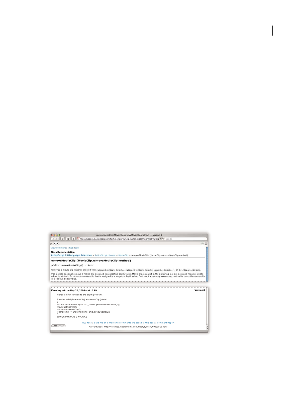
LiveDocs Help includes all the content from in-product Help, plus updates and links to additional instructional
content available on the web. For some products, you can also add comments to the topics in LiveDocs Help. Find
LiveDocs Help for your product in the Adobe Help Resource Center, at
www.adobe.com/go/documentation.
Page 9

ILLUSTRATOR CS3
User Guide
Most versions of in-product and LiveDocs Help let you search across the Help systems of multiple products. Topics
may also contain links to relevant content on the web or to topics in the Help of another product.
Think of Help, both in the product and on the web, as a hub for accessing additional content and communities of
users. The most complete and up-to-date version of Help is always on the web.
PDF documentation
The in-product Help is also available as a PDF that is optimized for printing. Other documents, such as installation
guides and white papers, may also be provided as PDFs.
All PDF documentation is available through the Adobe Help Resource Center, at www.adobe.com/go/documen-
tation. To see the PDF documentation included with your software, look in the Documents folder on the installation
or content DVD.
Printed documentation
Printed editions of the in-product Help are available for purchase in the Adobe Store, at www.adobe.com/go/store.
You can also find books published by Adobe publishing partners in the Adobe Store.
A printed workflow guide is included with all Adobe Creative Suite® 3 products, and stand-alone Adobe products
may include a printed getting started guide.
3
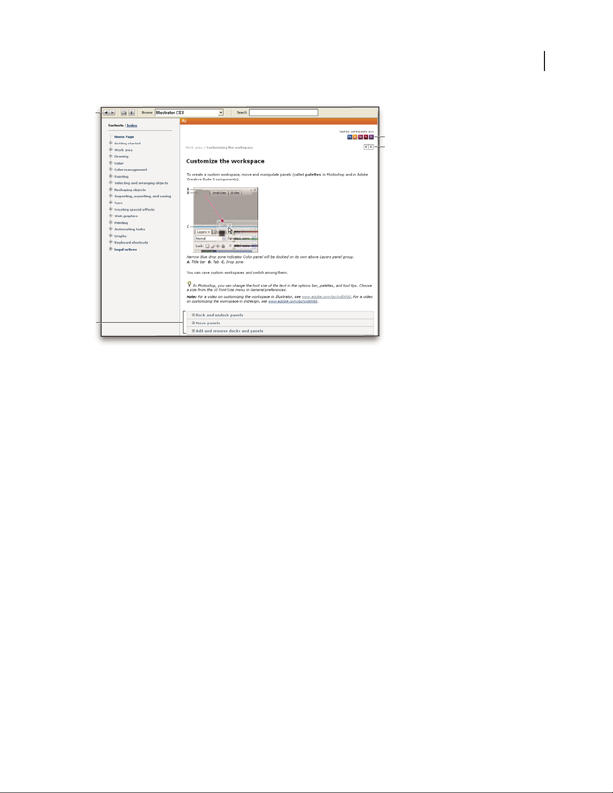
Using Help in the product
In-product Help is available through the Help menu. After you start the Adobe Help Viewer, click Browse to see Help
for additional Adobe products installed on your computer.
These Help features facilitate cross-product learning:
• Topics may contain links to the Help systems of other Adobe products or to additional content on the web.
• Some topics are shared across two or more products. For instance, if you see a Help topic with an Adobe
Photoshop® icon and an Adobe After Effects® icon, you know that the topic either describes functionality that is
similar in the two products or describes cross-product workflows.
• You can search across the Help systems of multiple products.
If you search for a phrase, such as “shape tool,” enclose it in quotation marks to see only those topics that include all
the words in the phrase.
Page 10
ILLUSTRATOR CS3
User Guide
A
C
D
B
4
Adobe Help
A. Back/Forward buttons (previously visited links) B. Expandable subtopics C. Icons indicating shared topic D. Previous/Next buttons (topics
in sequential order)
Accessibility features
Adobe Help content is accessible to people with disabilities—such as mobility impairments, blindness, and low
vision. In-product Help supports these standard accessibility features:
• The user can change text size with standard context menu commands.
• Links are underlined for easy recognition.
• If link text doesn’t match the title of the destination, the title is referenced in the Title attribute of the Anchor tag.
For example, the Previous and Next links include the titles of the previous and next topics.
• Content supports high-contrast mode.
• Graphics without captions include alternate text.
• Each frame has a title to indicate its purpose.
• Standard HTML tags define content structure for screen reading or text-to-speech tools.
• Style sheets control formatting, so there are no embedded fonts.
Keyboard shortcuts for Help toolbar controls (Windows)
Back button Alt+Left Arrow
Forward button Alt+Right Arrow
Print Ctrl+P
About button Ctrl+I
Browse menu Alt+Down Arrow or Alt+Up Arrow to view Help for another application
Search box Ctrl+S to place the insertion point in the Search box
Page 11
ILLUSTRATOR CS3
User Guide
Keyboard shortcuts for Help navigation (Windows)
• To move between panes, press Ctrl+Tab (forward) and Shift+Ctrl+Tab (backward).
• To move through and outline links in a pane, press Tab (forward) or Shift+Tab (backward).
• To activate an outlined link, press Enter.
• To make text bigger, press Ctrl+equal sign.
• To make text smaller, press Ctrl+hyphen.
Resources
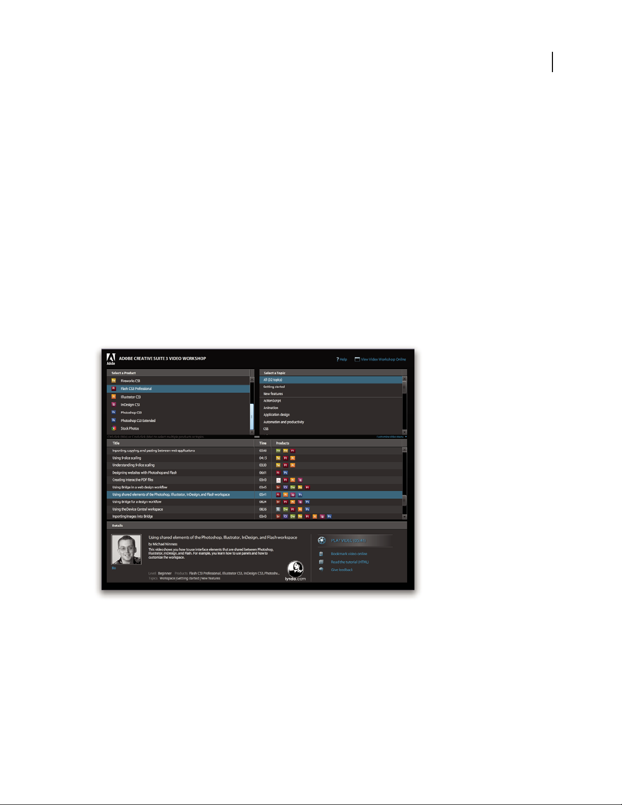
Adobe Video Workshop
The Adobe Creative Suite 3 Video Workshop offers over 200 training videos covering a wide range of subjects for
print, web, and video professionals.
You can use the Adobe Video Workshop to learn about any Creative Suite 3 product. Many videos show you how to
use Adobe applications together.
5
Page 12
ILLUSTRATOR CS3
User Guide
When you start the Adobe Video Workshop, you choose the products you want to learn and the subjects you want
to view. You can see details about each video to focus and direct your learning.
6
Community of presenters
With this release, Adobe Systems invited the community of its users to share their expertise and insights. Adobe and
lynda.com present tutorials, tips, and tricks from leading designers and developers such as Joseph Lowery, Katrin
Eismann, and Chris Georgenes. You can see and hear Adobe experts such as Lynn Grillo, Greg Rewis, and Russell
Brown. In all, over 30 product experts share their knowledge.
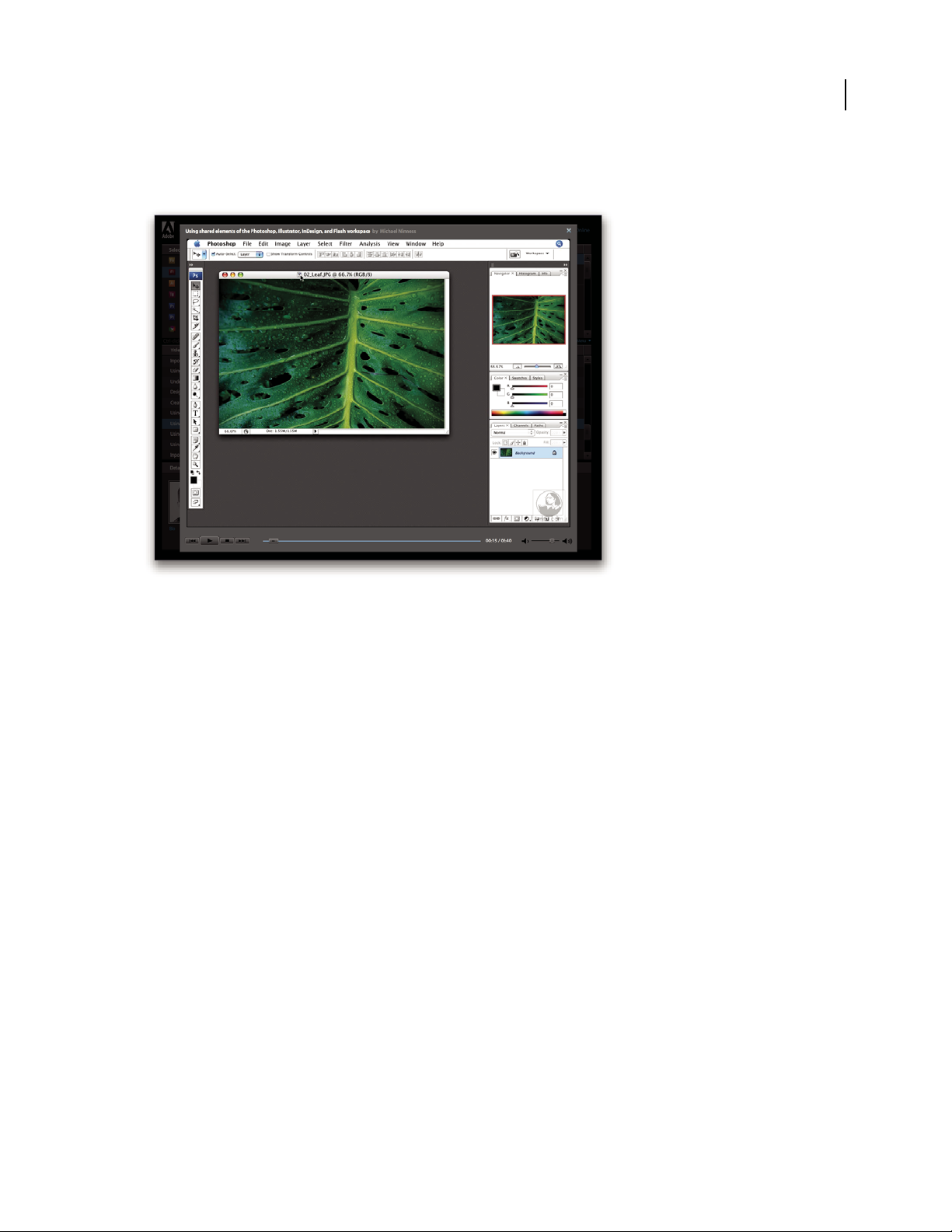
Tutorials and source files
The Adobe Video Workshop includes training for novices and experienced users. You’ll also find videos on new
features and key techniques. Each video covers a single subject and typically runs about 3-5 minutes. Most videos
come with an illustrated tutorial and source files, so you can print detailed steps and try the tutorial on your own.
Using Adobe Video Workshop
You can access Adobe Video Workshop using the DVD included with your Creative Suite 3 product. It’s also available
online at
www.adobe.com/go/learn_videotutorials. Adobe will regularly add new videos to the online Video
Workshop, so check in to see what’s new.
Illustrator CS3 videos
Adobe Video Workshop covers a wide range of subjects for Adobe Illustrator® CS3, including these:
• Creating and setting up a new document
• Importing content into Illustrator
• Selecting, manipulating, and aligning objects
• Using Smart Objects and Live Color
Page 13

ILLUSTRATOR CS3
User Guide
• Saving files for the web
Videos also show you how to use Illustrator CS3 with other Adobe products:
• Using text and symbols effectively between Illustrator and Flash®
• Creating mobile content in Illustrator
• Using shared elements in Photoshop, Illustrator, InDesign®, and Flash
• Exporting animated SWF files from Illustrator
To access Adobe Creative Suite 3 video tutorials, visit Adobe Video Workshop at
www.adobe.com/go/learn_videotutorials.
Extras
You have access to a wide variety of resources that will help you make the most of your Adobe software. Some of
these resources are installed on your computer during the setup process; additional helpful samples and documents
are included on the installation or content DVD. Unique extras are also offered online by the Adobe Exchange
community, at
Installed resources
During software installation, a number of resources are placed in your application folder. To view those files, navigate
to the application folder on your computer.
www.adobe.com/go/exchange.
7
• Windows®: [startup drive]/Program files/Adobe/Adobe [application]
• Mac OS®: [startup drive]/Applications/Adobe [application]
The application folder may contain the following resources:
Plug-ins Plug-in modules are small software programs that extend or add features to your software. Once installed,
plug-in modules appear as options in the Import or Export menu; as file formats in the Open, Save As, and Export
Original dialog boxes; or as filters in the Filter submenus. For example, a number of special effects plug-ins are
automatically installed in the Plug-ins folder inside the Photoshop CS3 folder.
Presets Presets include a wide variety of useful tools, preferences, effects, and images. Product presets include
brushes, swatches, color groups, symbols, custom shapes, graphic and layer styles, patterns, textures, actions,
workspaces, and more. Preset content can be found throughout the user interface. Some presets (for example,
Photoshop Brush libraries) become available only when you select the corresponding tool. If you don’t want to create
an effect or image from scratch, go to the preset libraries for inspiration.
Templates Template files can be opened and viewed from Adobe Bridge, opened from the Welcome Screen, or
opened directly from the File menu. Depending on the product, template files range from letterheads, newsletters,
Page 14

ILLUSTRATOR CS3
E
T
V
E
R
O
E
O
S
E
T
A
C
C
U
S
A
M
E
T
J
U
S
T
O
D
U
O
D
O
L
O
R
E
S
E
T
E
A
R
E
B
U
M
.
S
T
E
T
C
L
I
T
A
K
A
S
D
.
ET
C
O
S
E
T
E
T
U
R
S
A
D
I
P
S
C
I
N
G
01
Pelletir
Inc
.
C
O
R
E
I
N
V
E
S
T
M
E
N
T
S
P
E
C
T
R
U
M
Vel
i
ll
u
m
d
o
lore
e
u
fe
u
giat
n
u
ll
a
fac
ilis
is
at
vero
e
ros
e
t
a
cc
u
m
s
a
n
e
t
iu
s
to
o
d
io
d
i
gn
is
s
im
q
u
i.
R
E
T
I
R
E
M
E
N
T
S
A
V
I
N
G
P
L
A
N
Ve
l
ill
u
m
d
o
lore e
u
fe
u
giat
n
u
ll
a
fac
ilis
i
s
a
t vero
e
ro
s
e
t a
ccu
m
s
a
n
e
t
iu
s
to
o
d
io
d
i
gn
iss
im
q
u
i.
Y
o
u
r In
v
e
s
tm
e
n
t
G
u
id
e
A
r
e
y
o
u
l
e
a
v
in
g
m
o
n
e
y
o
n
t
h
e
t
a
b
l
e
?
0
1
Ty
p
i
n
o
n
h
a
b
e
nt c
la
ritate
m
in
s
it
a
m
;
e
s
t
u
s
u
s
l
e
g
ent
is
in ii
s
q
u
i fa
c
it
e
o
r
u
m
c
l
a
ritate
m
.
Inve
s
t
ig
ati
o
n
e
s
d
e
m
o
n
s
trave
r
u
nt l
e
ctore
s
le
g
e
re
m
e
l
i
u
s
q
u
o
d
ii
le
g
u
nt s
a
e
p
i
us. C
la
ritas
e
s
t
e
t
ia
m
p
roce
s
s
u
s.
Ty
p
i
n
o
n
h
a
b
ent
c
la
ritate
m
i
n
s
itam
;
e
s
t
u
s
u
s
l
e
g
ent
is
in
iis
q
u
i fa
c
i
t
e
o
r
u
m
c
la
ritate
m
.
Inve
s
t
ig
at
io
n
e
s
d
e
m
o
n
s
trave
r
u
nt
l
e
ctore
s
le
g
e
re
m
e
li
u
s
q
u
o
d
ii
le
g
u
nt
s
a
e
p
i
us. C
la
rit
a
s
e
s
t
e
t
ia
m
proce
s
s
u
s.
SU
R
V
I
C
E
M
E
N
U
N
U
L
C
H
E
vero
d
i
o
eu
m
n
ul
c
he
agiam
e
t ad
lorpe
ri
t
sum a
$
45
a
giam
e
t ad
atin
u
t
et
v
ero dio
e
u
m
n
u
l
che
su
m
a
ag
aim
et
ad
eu
m
n
ullam
$25
lo
r
p
e
r
it
sum
a
agiam
e
t ad
lo
rp
eri
t
vero dio
eum n
u
l
lam
$
35
SU
CCIVERO
S
sucicver
o
dio
ve
r
o dio
eu
m
n
ul
che
s
u
m
a
$15
eum
n
u
l
lam
vero dio
eum
n
u
l
c
he
su
m
a
agaim
e
t
a
d e
u
m
nu
l
lam
$3
5
N
eum n
ul
lam
$
35
S
UCC
I
VERO
S
su
cicver
o d
io
vero dio
eu
m
n
ul
c
he
su
m
a
$
1
5
e
um
nullam
ve
r
o d
io
eu
m
n
u
l
ch
e su
m
a
agaim
et
ad
e
um
nu
llam
$35
CC
a
s
i
o
p
i
a
S
p
A
User Guide
and websites to DVD menus and video buttons. Each template file is professionally constructed and represents a
best-use example of product features. Templates can be a valuable resource when you need to jump-start a project.
8
Travel Earth
Best 100 places to see on the planet
in your lifetime
Vel: Ad : Vulputate:
volute
ipsummy
, commy
re eugiarud tem
eraes-
exer
n ullutet
Samples Sample files include more complicated designs and are a great way to see new features in action. These files
demonstrate the range of creative possibilities available to you.
Fonts Several OpenType® fonts and font families are included with your Creative Suite product. Fonts are copied to
your computer during installation:
• Windows: [startup drive]/Program Files/Common Files/Adobe/Fonts
• Mac OS X: [startup drive]/Library/Application Support/Adobe/Fonts
For information about installing fonts, see the Read Me file on the installation DVD.
DVD content
The installation or content DVD included with your product contains additional resources for use with your
software. The Goodies folder contains product-specific files such as templates, images, presets, actions, plug-ins, and
effects, along with subfolders for Fonts and Stock Photography. The Documentation folder contains a PDF version
of the Help, technical information, and other documents such as specimen sheets, reference guides, and specialized
feature information.
Adobe Exchange
For more free content, visit www.adobe.com/go/exchange, an online community where users download and share
thousands of free actions, extensions, plug-ins, and other content for use with Adobe products.
Bridge Home
Bridge Home, a new destination in Adobe Bridge CS3, provides up-to-date information on all your Adobe Creative
3 software in one convenient location. Start Adobe Bridge, then click the Bridge Home icon at the top of the
Suite
Favorites panel to access the latest tips, news, and resources for your Creative Suite tools.
Page 15
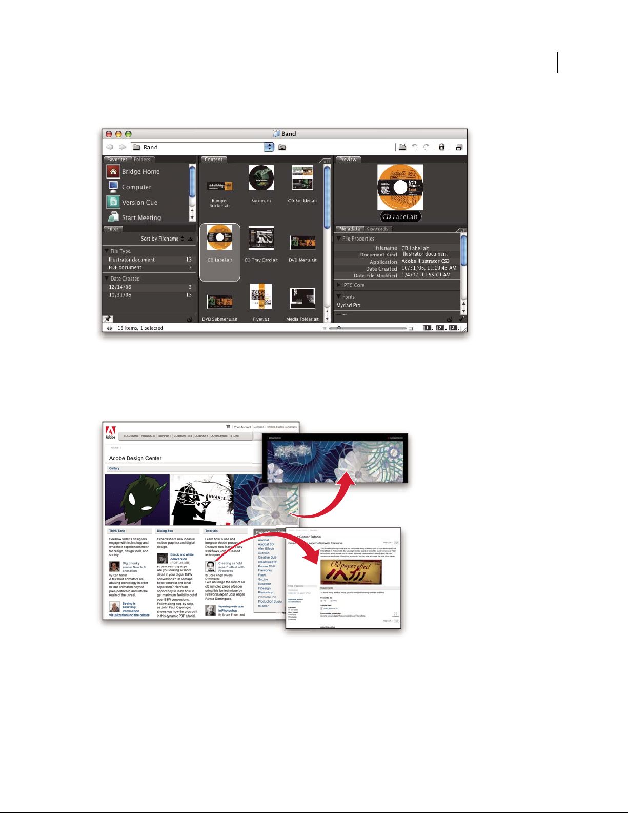
Note: Bridge Home may not be available in all languages.
ILLUSTRATOR CS3
User Guide
9
Adobe Design Center
Adobe Design Center offers articles, inspiration, and instruction from industry experts, top designers and Adobe
publishing partners. New content is added monthly.
You can find hundreds of tutorials for design products and learn tips and techniques through videos, HTML
tutorials, and sample book chapters.
Page 16
ILLUSTRATOR CS3
User Guide
New ideas are the heart of Think Tank, Dialog Box, and Gallery:
• Think Tank articles consider how today’s designers engage with technology and what their experiences mean for
design, design tools, and society.
• In Dialog Box, experts share new ideas in motion graphics and digital design.
• The Gallery showcases how artists communicate design in motion.
Visit Adobe Design Center at www.adobe.com/designcenter.
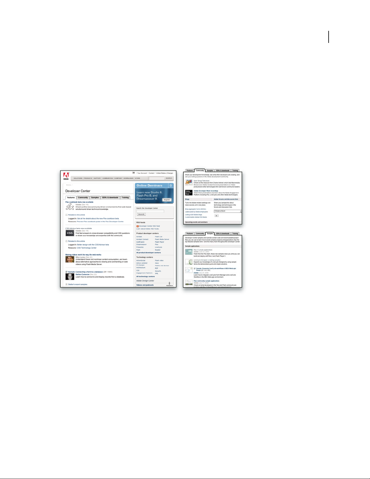
Adobe Developer Center
Adobe Developer Center provides samples, tutorials, articles, and community resources for developers who build
rich Internet applications, websites, mobile content, and other projects using Adobe products. The Developer Center
also contains resources for developers who develop plug-ins for Adobe products.
10
In addition to sample code and tutorials, you'll find RSS feeds, online seminars, SDKs, scripting guides, and other
technical resources.
Visit Adobe Developer Center at www.adobe.com/go/developer.
Customer support
Visit the Adobe Support website, at www.adobe.com/support, to find troubleshooting information for your product
and to learn about free and paid technical support options. Follow the Training link for access to Adobe Press books,
a variety of training resources, Adobe software certification programs, and more.
Downloads
Visit www.adobe.com/go/downloads to find free updates, tryouts, and other useful software. In addition, the Adobe
Store (at www.adobe.com/go/store) provides access to thousands of plug-ins from third-party developers, helping
you to automate tasks, customize workflows, create specialized professional effects, and more.
Page 17

ILLUSTRATOR CS3
User Guide
Adobe Labs
Adobe Labs gives you the opportunity to experience and evaluate new and emerging technologies and products from
Adobe.
At Adobe Labs, you have access to resources such as these:
• Prerelease software and technologies
• Code samples and best practices to accelerate your learning
• Early versions of product and technical documentation
• Forums, wiki-based content, and other collaborative resources to help you interact with like-minded developers
Adobe Labs fosters a collaborative software development process. In this environment, customers quickly become
productive with new products and technologies. Adobe Labs is also a forum for early feedback, which the Adobe
development teams use to create software that meets the needs and expectations of the community.
Visit Adobe Labs at www.adobe.com/go/labs.
User communities
User communities feature forums, blogs, and other avenues for users to share technologies, tools, and information.
Users can ask questions and find out how others are getting the most out of their software. User-to-user forums are
available in English, French, German, and Japanese; blogs are posted in a wide range of languages.
11
To participate in forums or blogs, visit www.adobe.com/communities.
What’s new
Superior design features
Live Color
Explore color harmonies and dynamically apply color at once to multiple vector graphics. With Live Color, you can
discover new color combinations, quickly test them, and then save and reuse them. You can preview changes to your
artwork, shift an artwork’s entire tone by playing with the color wheel, or merely adjust one color with maximum
precision. (See
Swatches panel
Save a color group to the Swatches panel so you can quickly refer back to a favorite set of colors. (See “Save Color
Guide colors to the Swatches panel” on page 112.)
Isolation mode
Use isolation mode to protect areas of an artwork from being edited. You can group, hide, lock, and restack layers
with confidence, knowing that isolated portions of your artwork will not be inadvertently changed. (See
groups and sublayers” on page 194.)
“Live Color overview” on page 112.)
“Isolate
Page 18

ILLUSTRATOR CS3
User Guide
Better integration
Integration with Adobe Flash
Create intricate vectors, storyboards, and test sequences without having to redraw them in Adobe Flash. Save
production time with type, layers, and symbols that maintain their structure and editability when you copy/past
them into Flash. You can move back and forth between Illustrator and Flash, harnessing the strengths of each
program. (See
Symbols
“Tag text for export to Flash” on page 331 and “About Flash graphics” on page 378.)
Take advantage of the power of Illustrator with symbols that are now more practical to create, more easily to
customize, and can be used in Flash with confidence. (See
Printing
“About symbols” on page 82.)
When printing, preserve native color spaces. Thanks to DeviceN support, you can be assured that your artwork will
separate correctly when it is printed. (See
“Printing color separations” on page 403.)
Enhanced workplace efficiency
New document profiles
Speed startup when you open a new document by selecting a pre-built New Document Profile. These profiles are
tailored for different kinds of projects—mobile, print, web, and video, for example. You can save custom profiles with
startup parameters such as artboard dimensions, swatches, brushes, styles, and color spaces. (See
document profiles” on page 33.)
“About new
12
Custom workspaces
Customize your workspace with collapsible panels and new icon views. You can save your workspace as a preset and
in so doing optimize your workspace for given tasks. (See
Operating performance
“Customize the workspace” on page 18.)
Work more fluidly and efficiently without waiting for Illustrator to catch up with your hands and your thoughts. The
underlying architecture of Illustrator has been improved. You’ll notice increased scroll and zoom times, snappier
refresh rates, and better responsiveness.
Access libraries from panels
Easily access libraries of pre-built brushes, thematic swatches, and graphic styles. Now you can quickly apply just the
effect you want by pulling down your library list with an icon located in the bottom bar of the tool panels. (See, for
example,
“Brushes panel overview” on page 166.)
Advanced drawing tools and controls
Control panel
Find the tool you need for the task at hand with the Control panel, which displays the options that are most appropriate for your current selection. You can access anchor-point controls, selection tools, clipping masks, and envelope
distortions from the top of the screen. Workspace clutter is reduced because you don’t have to keep as many panels
open. (See
“Control panel overview” on page 17.)
Page 19

ILLUSTRATOR CS3
User Guide
Path editing
As soon as you select points, the Control panel displays path-editing tools You can fine-tune your work faster and
even hide and show handles with one click. (See
Point selection
“Specify direction line and direction point appearance” on page 55.)
Run your cursor over any anchor point and enlarge it so you can easily see and select it. Your cursor shows a larger
square anywhere it detects a point. (See
Point alignment
“Specify anchor point size preferences” on page 55.)
Align and distribute points just like you align and distribute objects. When you select more than one point, the whole
range of alignment buttons appears in the Control panel. You can also align points to the artboard or a crop area.
“Align and distribute objects” on page 205.)
(See
Eraser tool
Quickly remove areas of artwork as easily as you can erase pixels in Photoshop. All you have to do is stroke the mouse
or stylus over any shape or set of shapes. Illustrator creates new paths along the edges of the erased stroke; the
smoothness of your erasure is preserved. (See
Crop Area tool
“Erase artwork” on page 75.)
Draw multiple crop areas with either custom or predefined characteristics. You can quickly create one-page PDFs
perfectly cropped to your selection, making it possible to save artwork variations to show clients and colleagues. (See
“Create, edit, and delete crop areas” on page 38.)
13
Page 20

Chapter 2: Work area
Welcome to Adobe® Illustrator® CS3. Illustrator gives you an efficient work area and user interface to create and edit
artwork for print, the web, and mobile devices.
Work area basics
Workspace overview
You create and manipulate your documents and files using various elements such as panels, bars, and windows. Any
arrangement of these elements is called a workspace. When you first start an Adobe Creative Suite component, you
see the default workspace, which you can customize for the tasks you perform there. For instance, you can create one
workspace for editing and another for viewing, save them, and switch between them as you work.
You can restore the default workspace at any time by choosing the default option on the Window > Workspace menu.
14
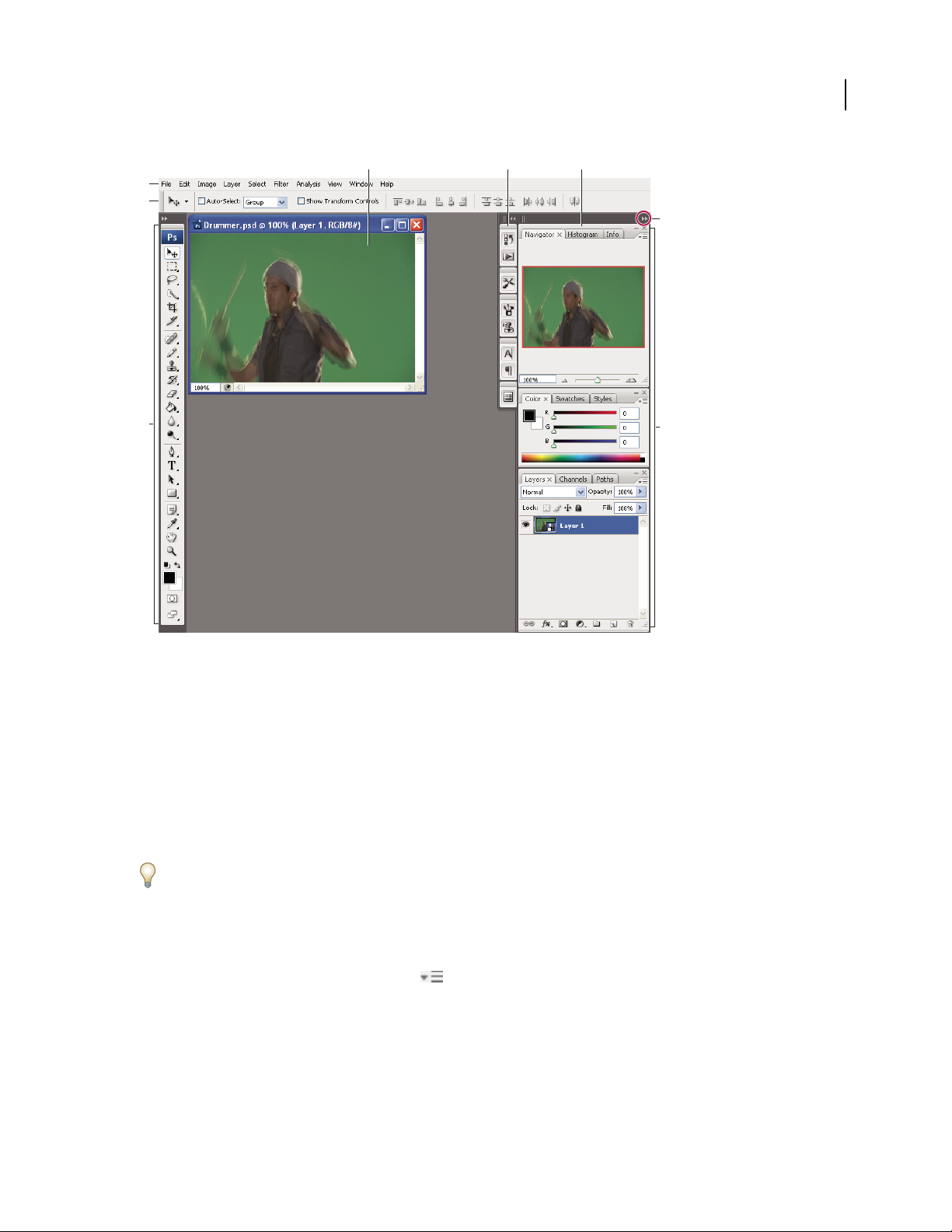
Although default workspaces vary across Flash, Illustrator, InCopy, InDesign, and Photoshop, you manipulate the
elements much the same way in all of them. The Photoshop default workspace is typical:
• The menu bar across the top organizes commands under menus.
• The Tools panel (called the Tools palette in Photoshop) contains tools for creating and editing images, artwork,
page elements, and so on. Related tools are grouped together.
• The Control panel (called the options bar in Photoshop) displays options for the currently selected tool. (Flash has
no Control panel.)
• The Document window (called the Stage in Flash) displays the file you’re working on.
• Panels (called palettes in Photoshop) help you monitor and modify your work. Examples include the Timeline in
Flash and the Layers palette in Photoshop. Certain panels are displayed by default, but you can add any panel by
selecting it from the Window menu. Many panels have menus with panel-specific options. Panels can be grouped,
stacked, or docked.
Page 21
ILLUSTRATOR CS3
User Guide
A B C
D
E
G
15
F
Default Photoshop workspace
A. Document window B. Dock of panels collapsed to icons C. Panel title bar D. Menu bar E. Options bar F. Tools palette G. Collapse To
Icons button H. Three palette (panel) groups in vertical dock
H
For a video on understanding the workspace, see www.adobe.com/go/vid0187.
Hide or show all panels
• (Illustrator, InCopy, InDesign, Photoshop) To hide or show all panels, including the Tools panel and options bar
or Control panel, press Tab.
• (Illustrator, InCopy, InDesign, Photoshop) To hide or show all panels except the Tools panel and options bar or
Control panel, press Shift+Tab.
You can temporarily display panels hidden by these techniques by moving the pointer to the edge of the application
window (Windows) or to the edge of the monitor (Mac OS) and hovering over the strip that appears.
• (Flash) To hide or show all panels, press F4.
Display panel menu options
❖ Position the pointer on the panel menu icon in the upper-right corner of the panel, and press the mouse
button.
(Illustrator) Adjust panel brightness
❖ In User Interface preferences, move the Brightness slider. This control affects all panels, including the Control
panel.
Page 22

ILLUSTRATOR CS3
User Guide
Reconfigure the Tools panel
You can display the tools in the Tools panel in a single column, or side by side in two columns.
In InDesign, you also can switch from single-column to double-column display by setting an option in Interface
preferences.
❖ Click the double arrow at the top of the Tools panel.
About screen modes
You can change the visibility of the illustration window and menu bar using the mode options at the bottom of the
Tools panel:
• Maximized Screen Mode displays artwork in a maximized window with a menu bar at the top, scroll bars on
the sides, and no title bar.
• Standard Screen Mode displays artwork in a standard window, with a menu bar at the top and scroll bars on
the sides.
• Full Screen Mode with Menu Bar displays artwork in a full-screen window with a menu bar but with no title
bar or scroll bars.
• Full Screen Mode displays artwork in a full-screen window, with no title bar, menu bar, or scroll bars.
16
Using the status bar
The status bar appears at the lower-left edge of the illustration window when you’re in Maximized Screen mode. It
displays the current zoom level and information about one of the following topics: the current tool in use, the date
and time, the number of undos and redos available, the document color profile, or the status of a managed file.
Click the status bar to do any of the following:
• Change the type of information displayed in the status bar by selecting an option from the Show submenu.
• Show the current file in Adobe Bridge by choosing Reveal In Bridge.
• Access Version Cue® commands.
Enter values in panels and dialog boxes
You enter values using the same methods in all panels and dialog boxes. You can also perform simple math in any
box that accepts numeric values. For example, if you want to move a selected object 3 units to the right using the
current measurement units, you don’t have to work out the new horizontal position—simply type +3 after the
current value in the Transform panel.
Enter a value in a panel or dialog box
❖ Do any of the following:
• Type a value in the box, and press Enter or Return.
• Drag the slider.
• Drag the dial.
• Click the arrow buttons in the panel to increase or decrease the value.
• Click in the box and then use the Up Arrow key and Down Arrow key on the keyboard to increase or decrease the
value. Hold down Shift and click an arrow key to magnify the increase rate or decrease rate.
Page 23
ILLUSTRATOR CS3
User Guide
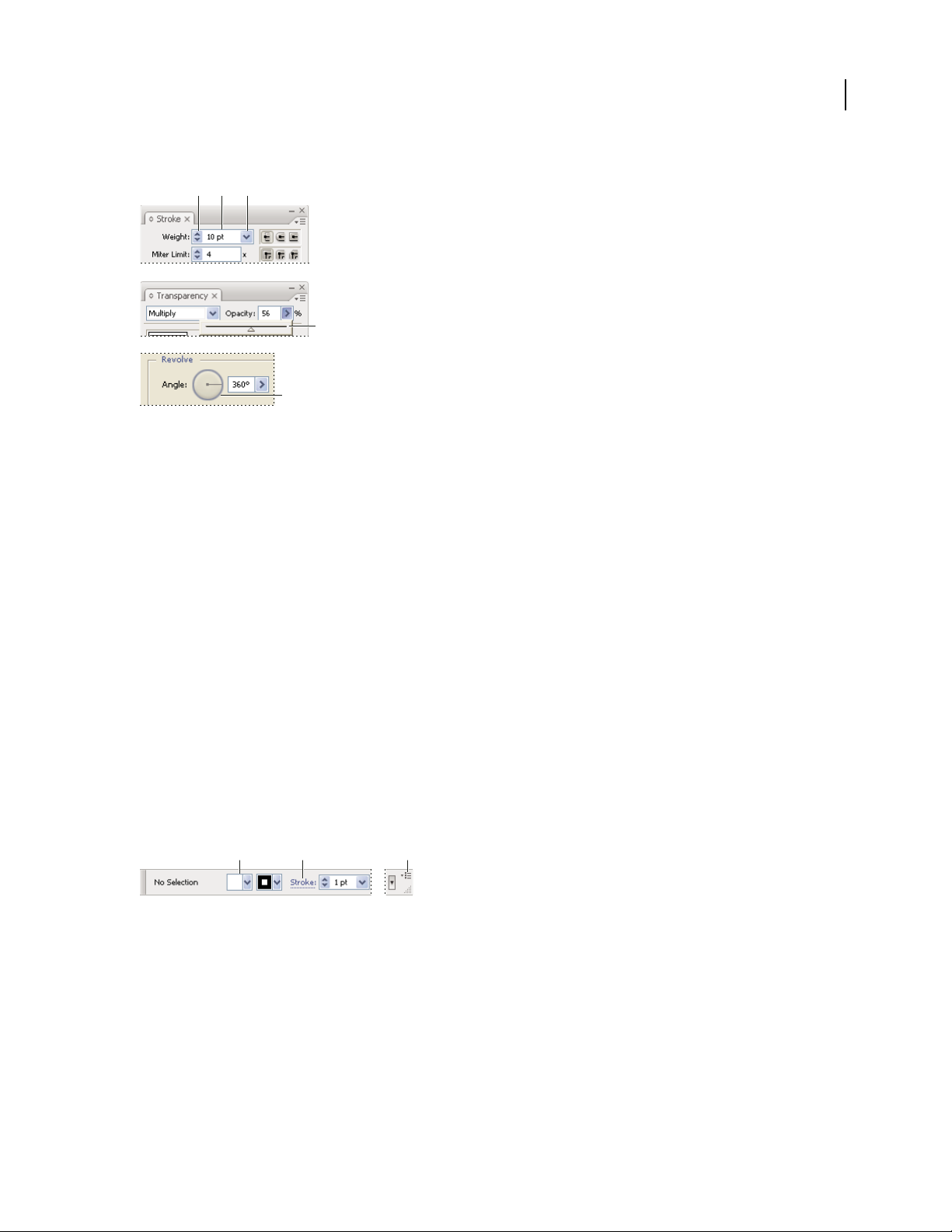
• Select a value from the menu associated with the box.
A B C
D
E
Ways to enter values
A. Arrow buttons B. Text box C. Menu arrow D. Slider E. Dial
Calculate values in a panel or dialog box
1
In a text box that accepts numerical values, do one of the following:
• To replace the entire current value with a mathematical expression, select the entire current value.
• To use the current value as part of a mathematical expression, click before or after the current value.
2 Type a simple mathematical expression using a single mathematical operator, such as + (plus), - (minus), x (multi-
plication), / (division), or % (percent).
For example, 0p0 + 3 or 5mm + 4. Similarly, 3cm * 50% equals 3 centimeters multiplied by 50%, or 1.50 cm, and
50pt + 25% equals 50 points plus 25% of 50 points, or 62.5 points.
17
3 Press Enter or Return to apply the calculation.
Control panel overview
The Control panel offers quick access to options related to the objects you select. By default, the Control panel is
docked at the top of the work area.
Options displayed in the Control panel vary depending on the type of object or tool you select. For example, when
you select a text object, the Control panel displays text-formatting options in addition to options for changing the
color, placement, and dimensions of the object.
A B C
Control panel
A. Hidden options B. Link to another panel C. Panel menu
When text in the Control panel is blue and underlined, you can click the text to display a related panel or dialog box.
For example, click the word Stroke to display the Stroke panel.
Change the kinds of controls that appear in the Control panel
❖ Select or deselect options in the Control panel menu.
Page 24
ILLUSTRATOR CS3
User Guide
Open and close a panel or dialog box from the Control panel
1
Click a blue underlined word to open its associated panel or dialog box.
2 Click anywhere outside of the panel or dialog box to close it.
Dock the Control panel at the bottom of the work area
❖ Choose Dock To Bottom from the Control panel menu.
Convert the Control panel to a floating panel
❖ Drag the gripper bar (located on the left edge of the panel) away from its current position.
To redock the Control panel, drag the gripper bar to the top or bottom of the application window (Windows) or
screen (Mac
OS).
Customizing the workspace
Customize the workspace
To create a custom workspace, move and manipulate panels (called palettes in Photoshop and in Adobe Creative
Suite 2 components).
18
A
B
C
Narrow blue drop zone indicates Color panel will be docked on its own above Layers panel group.
A. Title bar B. Tab C. Drop zone
You can save custom workspaces and switch among them.
In Photoshop, you can change the font size of the text in the options bar, palettes, and tool tips. Choose a size from
the UI Font Size menu in General preferences.
Note: For a video on customizing the workspace in Illustrator, see www.adobe.com/go/vid0032. For a video on custom-
izing the workspace in InDesign, see www.adobe.com/go/vid0065.
Dock and undock panels
A dock is a collection of panels or panel groups displayed together, generally in a vertical orientation. You dock and
undock panels by moving them into and out of a dock.
Note: Docking is not the same as stacking. A stack is a collection of free-floating panels or panel groups, joined top to
bottom.
• To dock a panel, drag it by its tab into the dock, at the top, bottom, or in between other panels.
• To dock a panel group, drag it by its title bar (the solid empty bar above the tabs) into the dock.
Page 25
ILLUSTRATOR CS3
User Guide
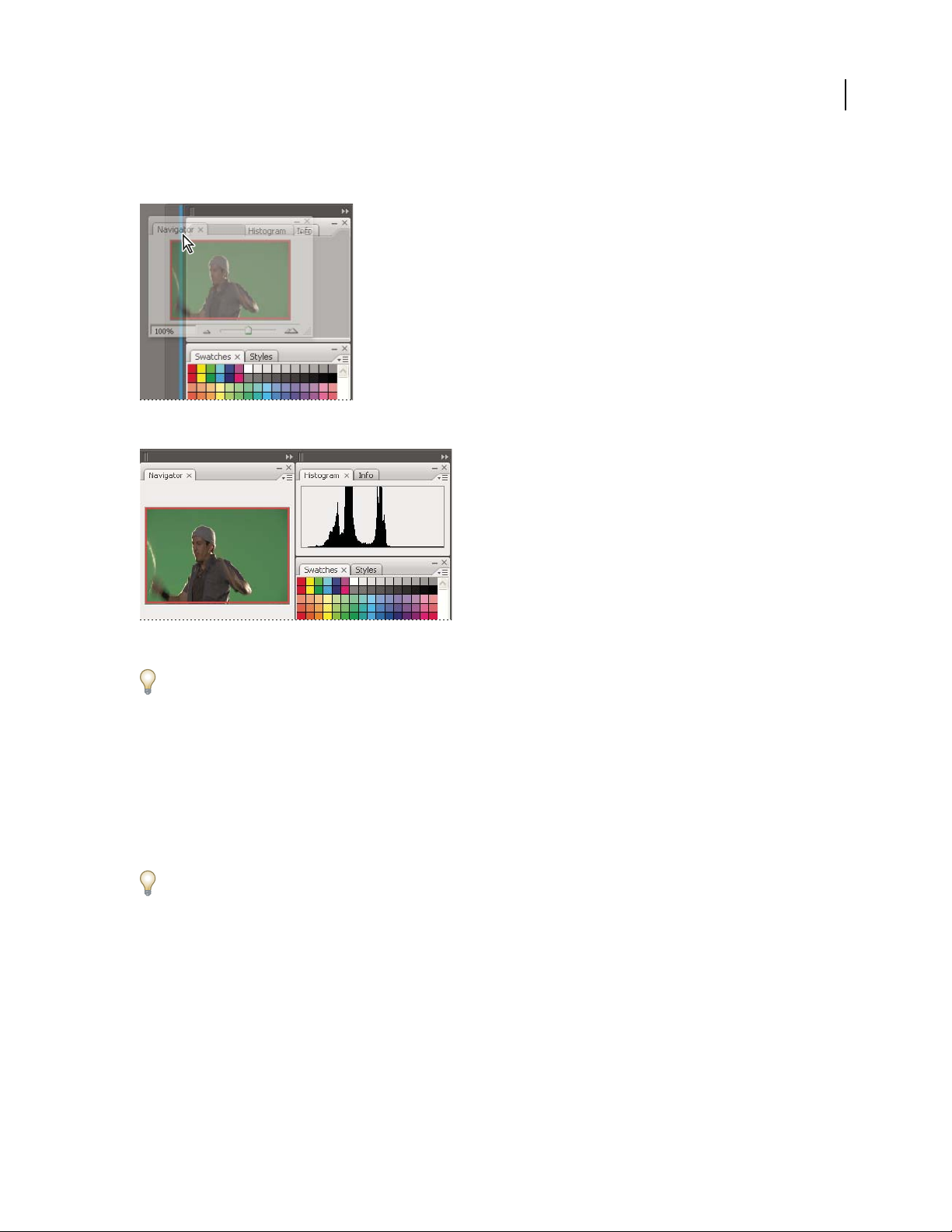
• To remove a panel or panel group, drag it out of the dock by its tab or title bar. You can drag it into another dock
or make it free-floating.
Navigator panel being dragged out to new dock, indicated by blue vertical highlight
19
Navigator panel now in its own dock
To prevent panels from filling all space in a dock, drag the bottom edge of the dock up so it no longer meets the edge
of the workspace.
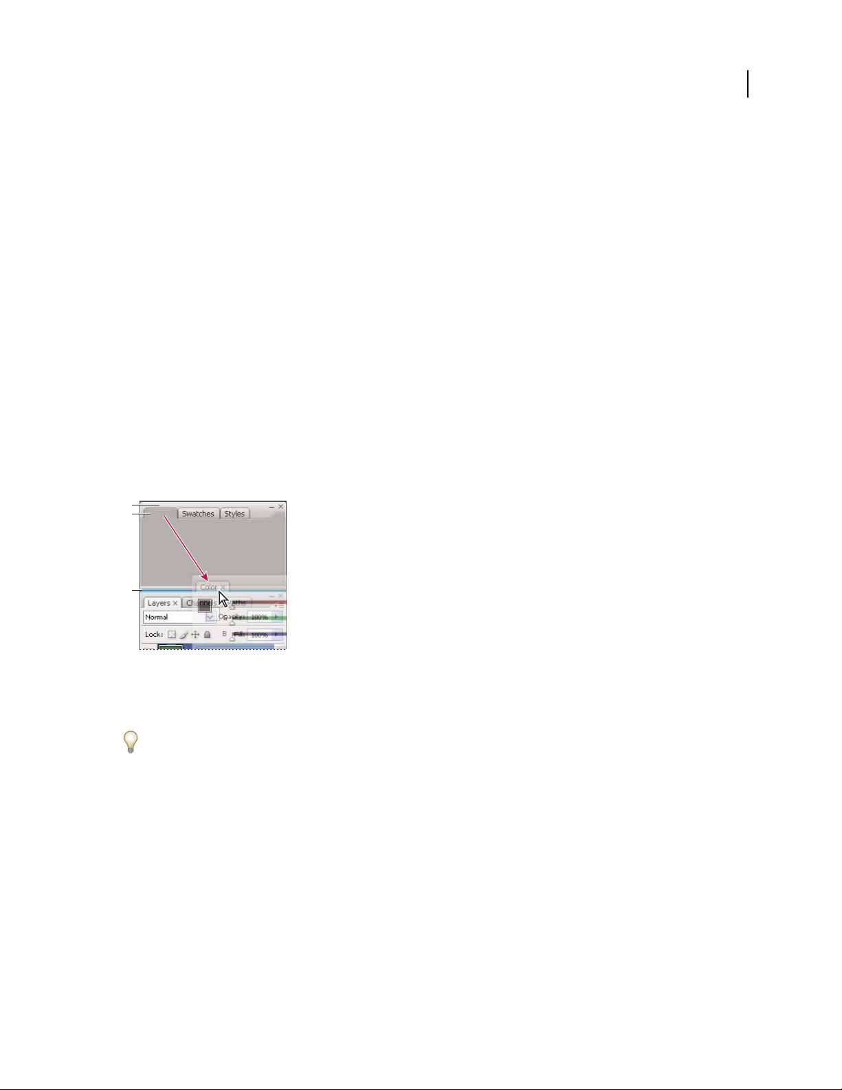
Move panels
As you move panels, you see blue highlighted drop zones, areas where you can move the panel. For example, you can
move a panel up or down in a dock by dragging it to the narrow blue drop zone above or below another panel. If you
drag to an area that is not a drop zone, the panel floats freely in the workspace.
• To move a panel, drag it by its tab.
• To move a panel group or a stack of free-floating panels, drag the title bar.
Press Ctrl (Windows) or Control (Mac OS) while moving a panel to prevent it from docking.
Add and remove docks and panels
If you remove all panels from a dock, the dock disappears. You can create new docks by moving panels to drop zones
next to existing docks or at the edges of the workspace.
• To remove a panel, click its close icon (the X at the upper-right corner of the tab), or deselect it from the Window menu.
• To add a panel, select it from the Window menu and dock it wherever you wish.
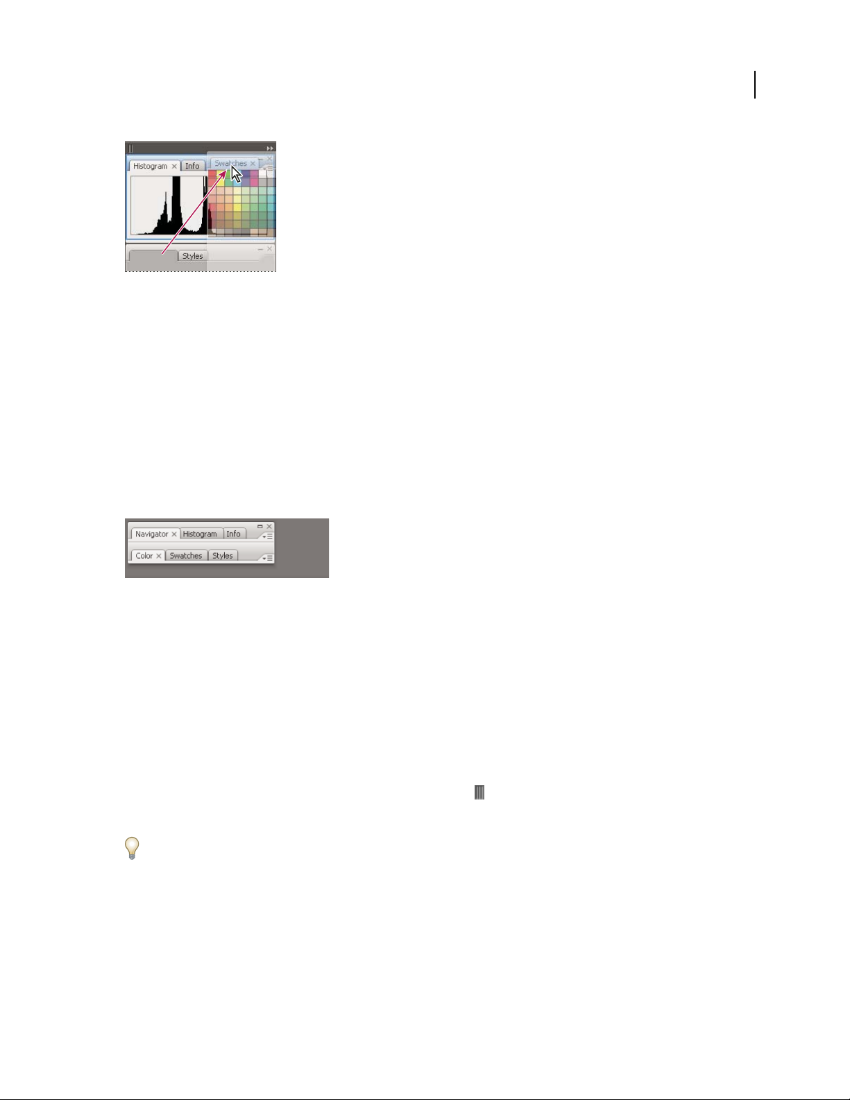
Manipulate panel groups
• To move a panel into a group, drag the panel’s tab to the highlighted drop zone at the top of the group.
Page 26
ILLUSTRATOR CS3
User Guide
Adding a panel to a panel group
• To rearrange panels in a group, drag a panel’s tab to a new location in the group.
• To remove a panel from a group so that it floats freely, drag the panel by its tab outside the group.
• To make a panel appear at the front of its group, click its tab.
• To move grouped panels together, drag their title bar (above the tabs).
Stack free-floating panels
When you drag a panel out of its dock but not into a drop zone, the panel floats freely, allowing you to position it
anywhere in the workspace. Panels may also float in the workspace when first selected from the Window menu. You
can stack free-floating panels or panel groups together so that they move as a unit when you drag the topmost title
bar. (Panels that are part of a dock cannot be stacked or moved as a unit in this way.)
20
Free-floating stacked panels
• To stack free-floating panels, drag a panel by its tab to the drop zone at the bottom of another panel.
• To change the stacking order, drag a panel up or down by its tab.
Note: Be sure to release the tab over the narrow drop zone between panels, rather than the broad drop zone in a title bar.
• To remove a panel or panel group from the stack, so that it floats by itself, drag it out by its tab or title bar.
Resize or minimize panels
• To resize a panel, drag any side of the panel or drag the size box at its lower-right corner. Some panels, such as the
Color panel in Photoshop, cannot be resized by dragging.
• To change the width of all the panels in a dock, drag the gripper at the top left of the dock.
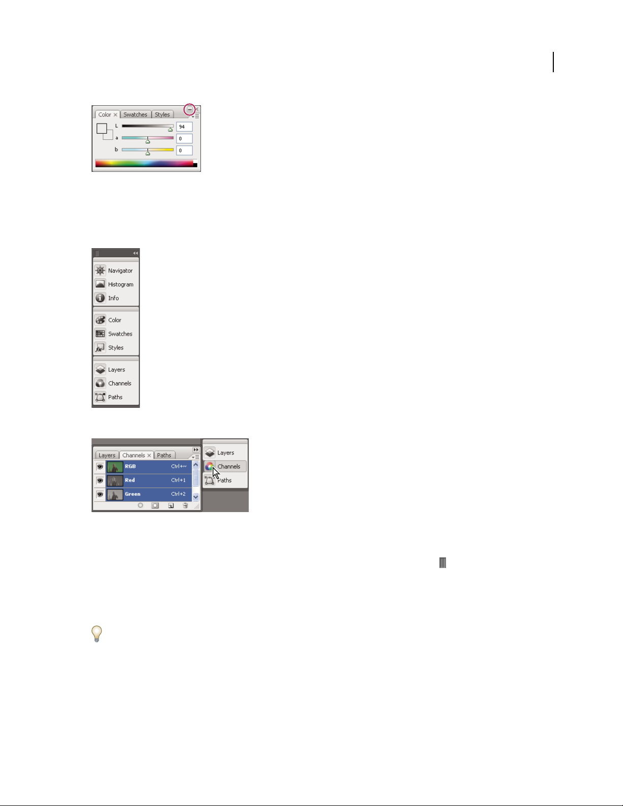
• To minimize a panel, panel group, or stack of panels, click the Minimize button in its title bar.
You can open a panel menu even when the panel is minimized.
Page 27
ILLUSTRATOR CS3
User Guide
Minimize button
Manipulate panels collapsed to icons
Collapse panels to icons to reduce clutter on the workspace. (In some cases, panels are collapsed to icons in the
default workspace.) Click a panel icon to expand the panel. You can expand only one panel or panel group at a time.
21
Panels collapsed to icons
Panels expanded from icons
• To collapse or expand all panels in a dock, click the double arrow at the top of the dock.
• To resize panel icons so that you see only the icons (and not the labels), drag the gripper at the top of the dock
toward the icons until the text disappears. (To display the icon text again, drag the gripper away from the panels.)
• To expand a single panel icon, click it.
• To collapse an expanded panel back to its icon, click its tab, its icon, or the double arrow in the panel’s title bar.
If you select Auto-Collapse Icon Panels from the Interface or User Interface Options preferences, an expanded panel
icon will collapse automatically when you click away from it.
• To add a panel or panel group to an icon dock, drag it in by its tab or title bar. (Panels are automatically collapsed
to icons when added to an icon dock.)
• To move a panel icon (or panel icon group), drag the bar that appears above the icon. You can drag panel icons up
and down in the dock, into other docks (where they appear in the panel style of that dock), or outside the dock
(where they appear as free-floating, expanded panels).
Page 28

ILLUSTRATOR CS3
User Guide
Rename or duplicate a workspace
1 Choose Window > Workspace > Manage Workspaces.
2 Do any of the following, and then click OK:
• To rename a workspace, select it, and edit the text.
• To duplicate a workspace, select it, and click the New button.
For a video on customizing the work area based on different workflows, see www.adobe.com/go/vid0032.
Save, delete, and switch between workspaces
By saving the current size and position of panels as a named workspace, you can restore that workspace even if you
move or close a panel. The names of saved workspaces appear in the Window
In Photoshop, the saved workspace can include a specific keyboard shortcut set and menu set.
Save a custom workspace
1
With the workspace in the configuration you want to save, do one of the following:
• (Photoshop, Illustrator, InDesign) Choose Window > Workspace > Save Workspace.
• (Flash) Choose Window > Workspace > Save Current, or choose Save Current from the Workspace menu in the
Edit bar.
• (Photoshop) Choose Save Workspace from the Workspace menu in the options bar.
2 Type a name for the workspace.
3 (Photoshop) Under Capture, select one or more options:
Palette Locations Saves the current palette locations.
> Workspace menu.
22
Keyboard Shortcuts Saves the current set of keyboard shortcuts.
Menus Saves the current set of menus.
4 Click OK.
Display or switch between workspaces
Flash, Illustrator, InDesign, and Photoshop include preset workspaces designed to make certain tasks easier.
• Choose Window > Workspace, and select a workspace.
• (Photoshop) Select a workspace from the Workspace menu in the options bar.
• (Flash) Select a workspace from the Workspace menu in the Edit bar.
(InDesign and Photoshop) Assign keyboard shortcuts to each workspace to navigate among them quickly.
Delete a custom workspace
• (Illustrator) Choose Window > Workspace > Manage Workspaces, select the workspace, and then click the Delete icon.
• (InDesign) Choose Window > Workspace > Delete Workspace, select the workspace, and then click Delete.
• (Flash) Choose Manage from the Workspace menu in the Edit bar, select the workspace, and then click Delete.
Alternatively, choose Window > Workspace > Manage, select the workspace, and then click Delete.
Page 29

ILLUSTRATOR CS3
User Guide
• (Photoshop) Choose Delete Workspace from the Workspace menu in the options bar. Alternatively, choose
Window > Workspace > Delete Workspace, select the workspace, and then click Delete.
(Photoshop) Start with the last or default palette locations
When you start Photoshop, palettes can either appear in their original default locations, or appear as you last used them.
❖ In Interface preferences:
• To display palettes in their last locations on startup, select Remember Palette Locations.
• To display palettes in their default locations on startup, deselect Remember Palette Locations.
Tools
Tools panel overview
The first time you start the application, the Tools panel appears at the left side of the screen. You can move the Tools
panel by dragging its title bar or the Illustrator icon. You can also show or hide the Tools panel by choosing
> Tools.
Window
You use tools in the Tools panel to create, select, and manipulate objects in Illustrator. Some tools have options that
appear when you double-click a tool. These include tools that let you use type, and select, paint, draw, sample, edit,
and move images.
23
Page 30

ILLUSTRATOR CS3
User Guide
You can expand some tools to show hidden tools beneath them. A small triangle at the lower-right corner of the tool
icon signals the presence of hidden tools. To see the name of a tool, position the pointer over it.
Tools panel overview
24
A
Selection tools
A
B
D
F
H
I
C
E
G
Selection (V)
Direct Selection (A)
Group Selection
Magic Wand ( Y)
Lasso (Q)
B
Drawing tools
Pen (P)
Add Anchor Point (+)
Delete Anchor (-)
Point
Convert Anchor
Point
Line Segment (\)
Arc
Spiral
Rectangular Grid
Polar Grid
Rectangle (M)
Rounded Rectangle
Ellipse (L)
Polygon
Star
Flare
Pencil (N)
Smooth
Path Eraser
Indicates default tool * Keyboard shortcuts appear in parenthesis
C
Type tools
Type (T)
Area Type
Type On a Path
Vertical Type
Vertical Area
Type
Vertical Type
On a Path
D
Painting tools
Paintbrush (B)
Mesh (U)
Gradient (G)
Eyedropper (I)
Measure
Live Paint Bucket (K)
Live Paint Selection
(Shift+L)
E
Reshaping tools
Rotate (R)
Reect (O)
Scale (S)
Shear
Reshape
Warp (Shift-R)
Twirl
Pucker
Bloat
Scallop
Crystallize
Wrinkle
Free Transform (E)
Blend (W)
F
Symbol tools
Symbol Sprayer
(Shift +S)
Symbol Shifter
Symbol Scruncher
Symbol Sizer
Symbol Spinner
Symbol Stainer
Symbol Screener
Symbol Styler
G
Graph tools
Column Graph (J)
Stacked Column
Graph
Bar Graph
Stacked Bar
Graph
Line Graph
Area Graph
Scatter Graph
Pie Graph
Radar Graph
H
Slicing and cutting
tools
Crop Area (Shift +O)
Slice (Shift+K)
Slice Select
Eraser (Shift +E)
Scissors (C)
Knife
I
Moving and zooming
tools
Hand (H)
Page
Zoom (Z)
View hidden tools
❖ Hold down the mouse button on the visible tool.
View tool options
❖ Double-click a tool.
Move the Tools panel
❖ Drag its title bar or the Illustrator icon.
Page 31

ILLUSTRATOR CS3
User Guide
Hide the Tools panel
❖ Choose Window > Tools.
Tear off hidden tools into a separate panel
❖ Drag the pointer over the arrow at the end of the Tools panel and release the mouse button.
Close a separate tool panel
❖ Click the close button on the panel’s title bar. The tools return to the Tools panel.
Select a tool
❖ Do one of the following:
• Click a tool in the Tools panel. If there is a small triangle at a tool’s lower-right corner, hold down the mouse button
to view the hidden tools, and then click the tool you want to select.
• Hold down Alt (Windows) or Option (Mac OS), and then click a tool to cycle through and select hidden tools.
• Press the tool’s keyboard shortcut. The keyboard shortcut is displayed in its tool tip. For example, you can select
the Move tool by pressing the V key.
To hid e t ool t i p s , ch o o se E dit > Preferences > General (Windows) or Illustrator > Preferences > General (Mac OS),
and deselect Show Tool Tips.
25
A B
C
D
E
Selecting a hidden tool
A. Tools panel B. Active tool C. Tear off panel with hidden tools D. Hidden tool triangle E. Tool name and shortcut
Change tool pointers
The mouse pointer for most tools matches the tool’s icon. Each pointer has a different hotspot, where an effect or
action begins. With most tools, you can switch to precise cursors, which appear as cross hairs centered around the
hotspot, and provide for greater accuracy when working with detailed artwork.
❖ Choose Edit > Preferences > General (Windows) or Illustrator > Preferences > General (Mac OS), and select Use
Precise Cursors. Alternatively, press Caps Lock on the keyboard.
Selection tool gallery
Illustrator provides the following selection tools:
Page 32

ILLUSTRATOR CS3
User Guide
26
The Selection tool (V) selects
entire objects.
The Lasso tool (Q) selects
points or path segments
within objects.
The Direct Selection tool (A)
selects points or path
segments within objects.
See also
“Keys for selecting” on page 464
Drawing tool gallery
Illustrator provides the following drawing tools:
The Group Selection tool
selects objects and groups
within groups.
The Magic Wand tool (Y)
selects objects with similar
attributes.
The Pen tool (P) draws
straight and curved lines to
create objects.
The Add Anchor Point tool
(+) adds anchor points to
paths.
The Delete Anchor Point tool
(-) deletes anchor points from
paths.
The Convert Anchor Point
tool (Shift+C) changes
smooth points to corner
points and vice versa.
Page 33

ILLUSTRATOR CS3
User Guide
27
The Line Segment tool (\)
draws individual straight line
segments.
The Polar Grid tool draws
circular chart grids.
The Arc tool draws
individual concave or convex
curve segments.
The Rectangle tool (M)
draws squares and
rectangles.
The Spiral tool draws
clockwise and counterclockwise spirals.
The Rounded Rectangle tool
draws squares and rectangles
with rounded corners.
The Rectangular Grid tool
draws rectangular grids.
The Ellipse tool (L) draws
circles and ovals.
The Polygon tool draws
regular, multi-sided shapes.
The Smooth tool smooths
Bezier paths.
The Star tool draws stars. The Flare tool creates lens-
flare or solar-flare-like
effects.
The Path Eraser tool erases
paths and anchor points from
the object.
The Pencil tool (N) draws
and edits freehand lines.
Page 34

Type tool gallery
Illustrator provides the following type tools:
ILLUSTRATOR CS3
User Guide
28
The Type tool (T) creates
individual type and type
containers and lets you enter
and edit type.
The Vertical Area Type tool
changes closed paths to
vertical type containers and
lets you enter and edit type
within them.
The Area Type tool changes
closed paths to type
containers and lets you enter
and edit type within them.
The Vertical Type On A Path
tool changes paths to vertical
type paths and lets you enter
and edit type on them
Painting tool gallery
Illustrator provides the following painting tools:
The Type On A Path tool
changes paths to type paths,
and lets you enter and edit
type on them.
The Ver tical Type tool creates
vertical type and vertical
type containers and lets you
enter and edit vertical type.
The Paintbrush tool (B)
draws freehand and calligraphic lines, as well as art
and patterns on paths.
The Mesh tool (U) creates
and edits meshes and mesh
envelopes.
The Gradient tool (G)
adjusts the beginning and
ending points and angle of
gradients within objects.
The Eyedropper tool (I)
samples and applies color,
type, and appearance
attributes, including effects,
from objects.
Page 35

ILLUSTRATOR CS3
User Guide
29
The Live Paint Bucket tool
(K) paints faces and edges of
Live Paint groups with the
current paint attributes.
The Live Paint Selection tool
selects faces and edges
within Live Paint groups.
The Measure tool measures
the distance between two
points.
Reshaping tool gallery
Illustrator provides the following tools for reshaping objects:
The Rotate tool (R) rotates
objects around a fixed point.
The Reflect tool (O) flips
objects over a fixed axis.
The Scale tool (S) resizes
objects around a fixed point.
The Shear tool skews objects
around a fixed point.
The Reshape tool adjusts
selected anchor points while
keeping the overall detail of
the path intact.
The Free Transform tool (E)
scales, rotates, or skews a
selection.
The Blend tool (W) creates a
series of objects blended
between the color and shape
of multiple objects.
Page 36

ILLUSTRATOR CS3
User Guide
30
The Warp tool (Shift+R)
molds objects with the
movement of the cursor (like
molding clay, for example).
The Scallop tool adds
random curved details to the
outline of an object.
The Twirl tool creates
swirling distor tions within an
object.
The Crystallize tool adds
random spiked details to the
outline of an object.
The Pucker tool deflates an
object by moving control
points towards the cursor.
The Wrinkle tool adds
wrinkle-like details to the
outline of an object.
The Bloat tool inflates an
object by moving control
points away from the cursor.
Symbolism tool gallery
The symbolism tools let you create and modify sets of symbol instances. You create a symbol set using the Symbol
Sprayer tool. You can then use the other symbolism tools to change the density, color, location, size, rotation, trans
parency, and style of the instances in the set.
-
The Symbol Sprayer tool
(Shift+S) places multiple
symbol instances as a set on
the artboard.
The Symbol Shifter tool
moves symbol instances
The Symbol Scruncher tool
moves symbol instances
closer together or farther
apart.
The Symbol Sizer tool resizes
symbol instances.
Page 37

ILLUSTRATOR CS3
User Guide
31
The Symbol Spinner tool
rotates symbol instances.
The Symbol Stainer tool
colorizes symbol instances.
The Symbol Screener tool
applies opacity to symbol
instances.
The Symbol Styler tool
applies the selected style to
symbol instances.
Graph tool gallery
Illustrator provides nine graph tools, each one for creating a different type of graph. The type of graph you choose
depends on the information you want to communicate.
80
70
60
50
40
30
20
10
0
B A
The Column Graph tool (J)
creates graphs that compare
values using vertical
columns.
100
80
60
40
20
0
B A
The Stacked Column graph
tool creates graphs that are
similar to column graphs, but
stacks the columns on top of
one another, instead of side
by side. This graph type is
useful for showing the
relationship of parts to the
total.
A
B
0 10 20 30 40 50 60 70 80
The Bar Graph tool creates
graphs that are similar to
column graphs, but positions
the bars horizontally instead
of vertically.
A
B
0 20 40 60 80 100
The Stacked Bar Graph tool
creates graphs that are
similar to stacked column
graphs, but stacks the bars
horizontally instead of vertically.
Page 38

ILLUSTRATOR CS3
User Guide
32
80
70
60
50
40
30
20
50 40 30 20 10
The Line Graph tool creates
graphs that use points to
represent one or more sets of
values, with a different line
joining the points in each set.
This type of graph is often
used to show the trend of one
or more subjects over a
period of time.
50
40
30
20
10
100
80
60
40
20
0
The Area Graph tool creates
graphs that are similar to line
graphs, but emphasizes totals
as well as changes in values.
50
40
30
20
10
0
10 20 30 40 50
The Scatter Graph tool
creates graphs that plot data
points as paired sets of
coordinates along the x and y
axes. Scatter graphs are
useful for identifying
patterns or trends in data.
They also can indicate
whether variables affect one
another.
D C B A
The Pie Graph tool creates
circular graphs whos e wedges
represent the relative
percentages of the values
compared.
The Radar Graph tool creates
graphs that compare sets of
values at given points in time
or in particular categories,
and is displayed in a circular
format. This type of graph is
also called a web graph.
Slicing and cutting tool gallery
Illustrator provides the following tools for slicing and cutting objects:
The Crop Area tool selects
specified areas for printing or
export.
The Slice tool div ides ar twork
into separate web images.
The Slice Selection tool selects
web slices.
The Eraser tool erases any
area of the object over which
you drag
Page 39

ILLUSTRATOR CS3
User Guide
33
The Scissors tool (C) cuts
paths at specified points.
The Knife tool cuts objects
and paths.
Moving and zooming tool gallery
Illustrator provides the following tools for moving around in and controlling the view of the artboard:
The Hand tool (H) moves the
Illustrator artboard within
the illustration window.
The Page tool adjusts the
page grid to control where
artwork appears on the
printed page.
The Zoom tool (Z) increases
and decreases the view
magnification in the illustration window.
Files and templates
About new document profiles
A document is the space in which you create artwork. In Illustrator, you can create documents destined for many
different types of output. (For information on creating Illustrator documents for video production, see the
Enhancing Video Production PDF at
You start a new document by choosing a new document profile based on your intended output. Each profile includes
preset values for size, color mode, units, orientation, transparency, and resolution. For example, the Video And Film
Document profile uses pixels instead of points, and you can choose a device-specific crop area, such as NTSC DV
Widescreen, to create a document in the exact dimensions required, with video-safe guides in place to help you lay
out your design for optimal viewing.
If you plan to output your file to a high-end printer, for example if you’re sending it to a service bureau, specify the
Print profile to ensure your artwork and any effects applied to the artwork are set to the proper resolution.
www.adobe.com/go/learn_ai_video.
Page 40

ILLUSTRATOR CS3
User Guide
You can choose from the following profiles:
Print Document Uses a default letter size artboard, and provides a variety of other preset print sizes to choose from.
Use this profile if you plan to send this file to a service bureau for output to a high-end printer.
Web Document Provides preset options optimized for output to the web.
Mobile And Devices Document Creates a small file size that is preset for a specific mobile device. You can choose
your device from the Size menu. Click Device Central to open Adobe Device Central and view the document layout
in a specified device interface.
Video And Film Document Provides several preset video- and film-specific crop area sizes (note that the Artboard
option changes to Crop Size for this profile). Illustrator creates only square pixel files, so to ensure that the sizes are
interpreted correctly in video applications, Illustrator adjusts the Width and Height values. For example, if you
choose NTSC DV Standard, Illustrator uses a pixel size of 648 x 480, which translates to 740 x 480 pixels in videobased applications.
Basic CMYK Document Uses a default letter size artboard, and provides a variety of other sizes to choose from. Use
this profile if you plan to send a document to multiple types of media. If one of the media types is a service bureau,
you’ll want to manually increase the Raster Effects setting to High.
Basic RGB Document Uses a default 800 x 600 size artboard, and provides a variety of other print-, video-, and web-
specific sizes to choose from. Do not use this option if you plan to send a document to a service bureau or output to
a high-end printer. Use this profile for documents that will be output to mid-level printers, to the web, or multiple
types of media.
34
For a video on setting up new documents, see www.adobe.com/go/vid0031.
Create new documents
You can create new Illustrator documents from a new document profile or from a template. Creating a document
from a new document profile gives you a blank document with the selected profile’s default fill and stroke colors,
graphic styles, brushes, symbols, actions, viewing preferences, and other settings. Creating a document from a
template gives you a document with preset design elements and settings, as well as content, such as cropmarks and
guides, for specific document types, such as brochures or CD covers.
You create a new document from the Welcome screen, or by using File > New or File > Device Central (for mobile
device output). The Welcome screen appears whenever a document is not currently open.
For a video on setting up new documents, see www.adobe.com/go/vid0031.
See also
“About new document profiles” on page 33
“About templates” on page 36
“About transparency” on page 173
Create a new document using the Welcome screen
1
Open Illustrator, or if Illustrator is already open, choose Help > Welcome Screen.
2 Do any of the following:
• Select a new document profile from the Create New list. The New Document dialog box opens with all options
set to the optimized values for the selected new document profile. You can change any of the preset values as
desired and click OK to open the new document.
Page 41

ILLUSTRATOR CS3
User Guide
Note: Alt-click (Windows) or Option-click (Mac OS) to open the new document directly and skip the New Document
dialog box.
• Select From Template in the Create New list. Select a template and click OK.
Create a custom document
You can customize any document by changing the settings in the New Document dialog box. However, it’s always
best to start with the new document profile that represents your intended output.
If you want to use the preset options from another Illustrator file or template, choose Browse from the New
Document Profile menu and open the file you want to use.
1 Do one of the following:
• Choose File > New. In the New Document dialog box, type a name for your document, and choose a new
document profile.
• In the Welcome Screen, choose a new document profile from the Create New list. In the New Document dialog
box, type a name for your document.
2 Specify options as desired to customize the document. Click Advanced to specify the following additional options:
Color Mode Specifies the color mode for the new document. Changing the color mode converts the default contents
(swatches, brushes, symbols, graphic styles) of the selected new document profile to a new color mode, resulting in
a color change. Watch for a warning icon when making changes.
35
Raster Effects Specifies the resolution for raster effects in the document. It is especially important to set this at High
when you plan to output to a high-end printer at high resolution. The Print profile sets this at High by default.
Transparency Grid Specifies the options for the transparency grid for documents that use the Video and Film profile.
Preview Mode Sets the default preview mode for the document (you can change this at any time by using the View
menu):
• Default displays artwork created in the document in vector view with full color. Zoom in/out retains smoothness
in the curves.
• Pixel displays artwork with a rasterized (pixilated) appearance. It does not actually rasterize the content, but
displays a simulated preview, as if the contents were rasters.
• Overprint provides an “ink preview” that approximates how blending, transparency, and overprinting will appear
in color-separated output. (See “About overprinting” on page 424.)
3 (Optional) If you choose the Mobile profile, you can preview your new document in the mobile device interface
by clicking Device Central.
Note: You can change these settings after you create the document by choosing File > Document Setup and specifying
new settings.
Create a new document from a template
❖ Do one of the following:
• Choose File > New From Template, select a template, and click New.
• Choose File > New. In the New Document dialog box, click Templates, select a template, and click New.
Page 42

ILLUSTRATOR CS3
User Guide
About templates
Te mp l at e s let you create new documents that share common settings and design elements. For example, if you need
to design a series of business cards with a similar look and feel, you can create a template with the desired artboard
size, view settings (such as guides), and print options. The template can also contain symbols for common design
elements (such as logos) and specific sets of color swatches, brushes, and graphic styles.
Illustrator comes with a variety of templates, including templates for letterhead, business cards, envelopes, brochures,
labels, certificates, postcards, greeting cards, and websites.
When a template is selected via the New From Template command, Illustrator creates a new document with identical
content and document settings as the template, but leaves the original template file untouched.
See also
“Create new documents” on page 34
Create a new template
1 Open a new or existing document.
2 Customize the document in any of the following ways:
• Set up the document window as you want it to appear in new documents you create from the template. This
includes the magnification level, scroll position, ruler origin, guides, grids, crop areas, and options in the View
menu.
• Draw or import any artwork you want to appear in new documents you create from the template.
• Delete any existing swatches, styles, brushes, or symbols, you don’t want to retain.
• Create any new swatches, styles, brushes, and symbols, you want in the corresponding panels. You can also import
preset swatches, styles, brushes, symbols, and actions from a variety of libraries that come with Illustrator.
• Create any graph designs you want and add them to the Graph Design dialog box. You can also import preset
graph designs.
• Set the desired options in the Document Setup dialog box and Print Options dialog box.
3 Choose File > Save As Template.
4 In the Save As dialog box, select a location for the file, enter a filename, and click Save.
Illustrator saves the file in AIT (Adobe Illustrator Template) format.
36
Open a file
You can open files that were created in Illustrator as well as files that were created in other applications.
• To open an existing file, choose File > Open. Locate the file, and click Open.
• To open a recently saved file, choose the file from the Open A Recent Item list in the Welcome screen, or choose
File > Open Recent Files, and choose a file from the list.
• To open and preview a file using Adobe Bridge, choose File > Browse to open Adobe Bridge. Locate the file and
choose File > Open With > Adobe Illustrator CS3.
Page 43

ILLUSTRATOR CS3
User Guide
See also
“Importing Adobe PDF files” on page 259
“Importing EPS files” on page 260
“Importing artwork from Photoshop” on page 262
Browse for files using Adobe Bridge
Adobe® Bridge is a cross-platform application included with Adobe® Creative Suite® 3 components that helps you
locate, organize, and browse the assets you need to create print, web, video, and audio content. You can start Bridge
from any Creative Suite component (except Adobe® Acrobat® 8), and use it to access both Adobe and non-Adobe
asset types.
❖ To open Adobe Bridge, do one of the following from within Illustrator:
• Choose File > Browse.
• Click the Adobe Bridge icon in the Control panel.
• Choose Reveal In Bridge from the status bar.
From Adobe Bridge, you can do any of the following:
• Manage image, footage, and audio files: Preview, search, sort, and process files in Bridge without opening
individual applications. You can also edit metadata for files, and use Bridge to place files into your documents,
projects, or compositions.
• Manage your photos: Import and edit photos from your digital camera card, group related photos in stacks, and
open or import Photoshop® Camera Raw files and edit their settings without starting Photoshop. You can also
search leading stock libraries and download royalty-free images by way of Adobe Stock Photos.
• Work with Adobe Version Cue®-managed assets.
• Perform automated tasks, such as batch commands.
• Synchronize color settings across color-managed Creative Suite components.
• Start a real-time web conference to share your desktop and review documents.
37
Adobe Version Cue
Adobe® Version Cue® is a file-version manager included with Adobe Creative Suite 3 Design, Web, and Master
Collection editions that consists of two pieces: the Version
Cue Server hosts Version Cue projects and PDF reviews, and can be installed locally or on a centralized
Ve rs i o n
computer. Version
Cue-enabled components (Adobe Acrobat®, Adobe Flash®, Adobe Illustrator®, Adobe InDesign®, Adobe
Ve rs i o n
InCopy®, Adobe Photoshop®, and Adobe Bridge).
Use Version Cue to track changes to a file as you work on it, and to enable workgroup collaboration such as file
sharing, version control, and online reviews. You can use Version
component, such as Photoshop, or across multiple components, such as Photoshop, Flash, and Illustrator.
You access Version Cue features by way of the Adobe dialog box or through Adobe Bridge, depending on whether
you are using Version
example, Adobe Creative Suite 3 Design Premium).
Cue connectivity enables you to connect to Version Cue Servers, and is included with all
Cue-enabled software and whether or not you have installed a Creative Suite software set (for
Cue Server and Version Cue connectivity. The
Cue in a single Version Cue-enabled Creative Suite
Page 44

ILLUSTRATOR CS3
User Guide
Ve rs i o n Cue handles the following tasks:
• Creating versions of your files
• Enabling workgroup collaboration (file sharing, version control, the ability to check files in and out)
• Organizing files into private or shared projects
• Providing thumbnails so you can browse and view files
• Organizing data so you can view and search on file information, version comments, and file status
• Creating and managing user access, projects, and PDF reviews by way of Version Cue Server Administration
Cropping artwork
Create, edit, and delete crop areas
The crop area sets the position of the printer’s marks on your document and defines the exportable boundaries of
the artwork. By default, Illustrator crops artwork to the boundaries of the artboard, which you specify when you
select a document profile in the New Document dialog box. However, you can choose to crop your artwork to a
preset crop area or to a custom crop area that you define.
38
You can create multiple crop areas for your document, but only one crop area can be active at a time. When you have
multiple crop areas defined, you can view them all by selecting the Crop tool and pressing Alt. Each crop area is
numbered for easy reference. You can edit or delete a crop area at any time, and you can specify different crop areas
each time you print or export.
Crop area boundaries are represented by a dashed line surrounding the artwork—areas outside of the crop area
appear dimmed while the Crop Area tool is active. You can also choose to display a center mark, cross hairs, video
safe and screen edge markers, and rulers around the crop area.
To see a video on using the Crop Area tool, see www.adobe.com/go/vid0213.
Define a single crop area
1
Do one of the following:
• To define a custom crop area using the Crop Area tool, select the Crop Area tool and drag in the work area to
define the crop area.
• To use a preset crop area, double-click the Crop Area tool, select a preset for the crop area size in the Crop Area
Options dialog box, and click OK. Drag the crop area to position it where you want.
If you want the artwork to contain a bleed, make sure that there’s enough artwork beyond the crop area rectangle to
accommodate the bleed.
2 To commit the crop area and exit the crop-editing mode, click a different tool in the Tools panel.
Define and view additional crop areas
❖ Select the Crop Area tool, and then do any of the following:
• To create a new crop area, hold down Alt and drag. Each crop area has a unique number in the upper-left corner.
• To view all crop areas, press Alt.
• To set a crop area as the active crop area, hold down Alt and click the crop area you want active.
Page 45

ILLUSTRATOR CS3
User Guide
• To rotate between crop areas, press Alt and click an arrow key.
Delete a crop area
❖ Select the Crop Area tool, and do one of the following:
• To delete the active crop area, click Delete in the Control panel.
• To delete one of multiple crop areas, hold down Alt to view all existing crop areas, and click the Delete icon in
the upper-right corner of the crop area you want to delete.
• To delete all crop areas, click Delete All in the Control panel or press Alt+Delete.
Edit or move a crop area
❖ Select the Crop Area tool, and do one of the following:
• To edit the crop area, position the pointer on an edge or corner of the crop area, and, when the cursor changes to
a double-sided arrow, drag to adjust. Or, specify new Width and Height values in the Control panel.
• To move the crop area, position the pointer in the middle of the crop area and when the cursor changes to a four-
sided arrow drag it. Or you can select it and press an arrow key (press Shift+arrow key to move in 10 point increments), or specify new X and Y values in the Control panel.
39
Use crop area rulers
You can display rulers by selecting Show Crop Area Rulers in the Crop Area Options dialog box, which you open by
double-clicking the Crop Area tool. Rulers are useful when you’re working with art intended for export to video. The
numbers on the rulers reflect device-specific pixels, regardless of the measurement unit specified in preferences. The
default Pixel Aspect Ratio (PAR) for Illustrator is 1.0 (for square pixels)—this value changes according to the crop
area preset you choose either in the Crop Area Options dialog box or the New Document dialog box.
If you’re using nonsquare pixels, the ruler provides for easier device-specific pixel calculations. For example, if you
specify a crop area of 100 x100 Illustrator points, and you want to know the exact size in device-dependent pixels
before exporting the file for use in a NTSC DV Widescreen, you can set the crop area ruler in Illustrator to use a pixel
aspect ratio of 1.2 (for wide pixels) and the ruler will reflect the change and display the crop area as 83 x100 device
pixels (100/1.2 = 83.333).
Crop area with rulers
1 Double-click the Crop Area tool in the Tools panel.
2 Select Show Crop Area Rulers and set a value for Ruler Pixel Aspect Ratio.
Page 46

ILLUSTRATOR CS3
User Guide
Crop area options
You open the Crop Area Options dialog box by double-clicking the Crop Area tool. You can also specify many of
these options in the Control panel when the Crop Area tool is active.
Preset Specifies crop area dimensions. These presets set the ruler Pixel Aspect Ratio appropriately for the specified
output.
Width and Height Specifies the size of the crop area.
Constrain Proportions Keeps the aspect ratio of the crop area intact if you manually resize the crop area.
X: and Y: Position Specifies the position of the crop area according to Illustrator’s work area rulers. To view these
rulers, choose View > Show Rulers.
Show Center Mark Displays a point in the center of the crop area.
Show Cross Hairs Displays cross lines through the center of each side of the crop area.
Show Video Safe Areas Displays guides that represent the areas that fall inside the viewable area of video. You want
to keep all text and art that must be viewable to users inside the video safe areas.
Show Screen Edge Displays guides that represent the edge of the video screen.
40
Show Crop Area Rulers
Displays rulers around the crop area. The zero point of these rulers is in the upper-left corner,
as with video rulers. The dimensions reflected are determined by the value in the Ruler Pixel Aspect Ratio box.
Ruler Pixel Aspect Ratio Specifies the pixel aspect ratio used for the rulers.
Fade Region Outside Crop Area Displays the area outside of the crop area a darker shade than the area inside the
crop area when the Crop tool is active.
Update While Dragging Keeps the area outside of the crop area darker as you drag to resize the crop area. If this is
not selected, the outside area displays in the same color as inside the crop area while resizing.
Crop Areas Indicates how many crop areas exist.
Specify how to crop artwork for printing
1 Choose File > Print.
2 Select Setup on the left side of the Print dialog box.
3 For Crop Artwork To, specify whether to crop the artwork to the artboard, to the bounding box of all artwork in
the document, or to the defined crop area.
If you want to crop artwork to the crop area, you must first define the crop area.
Specify crop marks for trimming or aligning
In addition to specifying how to crop artwork for output, you can also create and use multiple sets of crop marks
within your artwork. Crop marks indicate where you want the printed paper to be cut. Crop marks are useful when
you want to create marks around several objects on a page—for example, when printing a sheet of business cards.
They are also helpful for aligning Illustrator artwork that you’ve exported to another application.
Crop marks differ from the crop area in the following ways:
• Crop areas specify the printable boundaries of artwork, whereas crop marks don’t affect the printed area at all.
• You can activate only one crop area at a time, whereas you can create and display multiple crop marks.
Page 47

ILLUSTRATOR CS3
User Guide
• The crop area is indicated by visible but non-printing marks, whereas crop marks are printed with registration
black (so that they print to every separation plate, similar to printer’s marks).
Note: Crop marks do not replace trim marks created with the Marks & Bleed options in the Print dialog box or with the
Object > Crop Area > Make command.
Create crop marks around an object
1
Select the object or objects.
2 Choose Filter > Create > Crop Marks.
Delete crop marks
❖ Select the crop mark and press Delete.
Use Japanese-style crop marks
Japanese-style crop marks have double lines, which visually define a default bleed value of 8.5 points (3 millimeters).
1 Choose Edit > Preferences > General (Windows) or Illustrator > Preferences > General (Mac OS).
2 Select Use Japanese Crop Marks, and then click OK.
41
Viewing artwork
Artboard overview
The artboard represents the entire region that can contain printable artwork. However, the artboard’s dimensions do
not necessarily match the current page size. For example, your artboard may be 10 x 20 inches while your print
settings specify 8-1/2 x 11 inch paper, or 864 x 480 pixels. You can view the page boundaries in relation to the
artboard by showing page tiling (View
areas are represented by a series of solid and dotted lines between the outermost edge of the window and the
printable area of the page.
A
B
C
D
> Show Page Tiling). When page tiling is on, the printable and nonprintable
Illustration window
A. Printable area B. Nonprintable area C. Edge of the page D. Artboard
Page 48

ILLUSTRATOR CS3
User Guide
The printable area is bounded by the innermost dotted lines and represents the portion of the page on which the
selected printer can print. Many printers cannot print to the edge of the paper.
The nonprintable area is between the two sets of dotted lines representing any nonprintable margin of the page.
The page edge is indicated by the outermost set of dotted lines.
The artboard is bounded by solid lines and represents the maximum printable area. To hide the artboard boundaries,
choose View
> Hide Artboard.
The scratch area is the area outside the artboard that extends to the edge of the 227-inch square window. The scratch
area represents a space on which you can create, edit, and store elements of artwork before moving them onto the
artboard. Objects placed onto the scratch area are visible on-screen, but they do not print.
See also
“Change the page size and orientation” on page 407
“Reposition artwork on the page” on page 406
“Print artwork on multiple pages” on page 406
Change the size and color of the artboard
1 Choose File > Document Setup.
2 From the menu at the upper-left of the Document Setup window, do either of the following:
• To change the size of the artboard, choose Artboard, and then set the size and orientation for the artboard.
• To change the color of the artboard, choose Transparency. Select Simulate Colored Paper, click the top color
swatch, and select a new color using the Color dialog box.
42
Changing the color of the artboard lets you view your document as it might appear when printed on colored paper.
For example, if you draw a blue object on a yellow background, the object appears green. The simulation is only
performed when the transparency grid is not shown.
About page tiling
By default, Illustrator prints your artwork on a single sheet of paper. However, if the artwork is larger than the page
sizes available on your printer, you can print onto multiple sheets of paper.
Dividing the artboard to fit a printer’s available page sizes is called tiling. You can choose a tiling option in the Setup
section of the Print dialog box. To view the page tiling boundaries on the artboard, choose View
> Show Page Tiling.
Page 49

ILLUSTRATOR CS3
User Guide
Artboard divided into multiple page tiles
When you divide the artboard into multiple page tiles, the pages are numbered from left to right and from top to
bottom, starting with page 1. These page numbers appear on-screen for your reference only; they do not print. The
numbers enable you to print all of the pages in the file or specify particular pages to print.
See also
“Change the page size and orientation” on page 407
43
“Print artwork on multiple pages” on page 406
Zoom in or out
There are several ways to zoom in or out of artwork.
• Select the Zoom tool . The pointer becomes a magnifying glass with a plus sign in its center. Click in the center
of the area that you want to magnify, or hold down Alt (Windows) or Option (Mac OS) and click in the center of
the area that you want to reduce. Each click magnifies or reduces the view to the previous preset percentage.
• Select the Zoom tool and drag a dotted rectangle, called a marquee, around the area you want to magnify. To move
the marquee around the artwork, hold down the spacebar, and continue dragging to move the marquee to a new
location.
• Choose View > Zoom In or View > Zoom Out. Each click magnifies or reduces the view to the next preset
percentage.
• Set the zoom level at the lower-left corner of the main window or in the Navigator panel.
• To display a file at 100%, choose View > Actual Size, or double-click the Zoom tool.
• To change the view to fit the document window, choose View > Fit In Window, or double-click the Hand tool.
See also
“Moving and zooming tool gallery” on page 33
“Keys for viewing artwork” on page 462
Page 50

ILLUSTRATOR CS3
User Guide
Move the view area
You can bring a different area of the artboard into view by doing either of the following:
• Select the Hand tool , and drag in the direction you want the artwork to move.
• In the Navigator panel, click the area of the thumbnail display that you want to view in the illustration window.
Alternatively, drag the proxy view area (the colored box) to a different area of the thumbnail display.
To specify the quality of the display when using the Hand tool, choose Edit > Preferences > Units & Display Perfor-
mance (Windows) or Illustrator > Preferences > Units & Display Performance (Mac OS). Drag the Hand Tool slider
left to improve the quality of the view when you move it with the Hand tool, or right to improve the speed at which you
can move the view with the Hand tool.
See also
“Moving and zooming tool gallery” on page 33
“Keys for viewing artwork” on page 462
Navigator panel overview
You use the Navigator panel (Window > Navigator) to quickly change the view of your artwork using a thumbnail
display. The colored box in the Navigator (called the proxy view area) corresponds to the currently viewable area in
the illustration window.
44
A
CDE FG
Navigator panel
A. Thumbnail display of artwork B. panel menu button C. Zoom box D. Zoom Out button E. Proxy preview area F. Zoom slider G. Zoom
In button
B
You can customize the Navigator panel in the following ways:
• To display artwork outside the boundaries of the artboard in the Navigator panel, click View Artboard/Crop Area
Only from the panel menu to deselect it.
• To change the color of the proxy view area, select panel Options from the panel menu. Select a preset color from
the Color menu, or double-click the color box to choose a custom color.
• To display dashed lines in the document as solid lines in the Navigator panel, select panel Options from the panel
menu and select Draw Dashed Lines As Solid Lines.
• To specify the size at which text is replaced by a gray bar in the Navigator panel, select panel Options from the
panel menu and enter a font size in the Greeking box.
See also
“Customize the workspace” on page 18
Page 51

ILLUSTRATOR CS3
User Guide
View artwork as outlines
By default, Adobe Illustrator sets the view so that all artwork is previewed in color. However, you can choose to
display artwork so that only its outlines (or paths) are visible. Viewing artwork without paint attributes speeds up the
time it takes to redraw the screen when working with complex artwork.
In Outline mode, linked files are displayed by default as outlined boxes with an X inside. To view the contents of
linked files, choose File
Outline.
• To view all artwork as outlines, choose View > Outline. Choose View > Preview to return to previewing artwork
in color.
• To view all artwork in a layer as outlines, Ctrl-click (Windows) or Command-click (Mac OS) the eye icon for the
layer in the Layers panel. Ctrl-click (Windows) or Command-click (Mac OS) again to return to previewing
artwork in color. The eye icon has a hollow center when Outline view is enabled and a filled center when
Preview view is enabled.
• To view all items in unselected layers as outlines, Alt+Ctrl-click (Windows) or Option+Command-click (Mac OS)
the eye icon for the selected layer. Alternatively, select Outline Others from the Layers panel menu.
You can return all items in the Layers panel to Preview mode by choosing Preview All Layers from the Layers panel
menu.
> Document Setup, choose Artboard at the top of the dialog box, and select Show Images In
45
See also
“Layers panel overview” on page 211
Use multiple windows and views
You can open multiple windows of a single document at the same time. Each window can have different view
settings. For
another window less magnified for laying out those objects on the page.
windows edge to edge; Arrange Icons organizes minimized windows within the program window.
An alternative to creating multiple windows is creating multiple views. You can create and store up to 25 views for
each document.
Multiple windows and multiple views differ in the following ways:
• Multiple views are saved with the document, multiple windows are not.
• Multiple windows can be viewed at the same time.
• Multiple views can only appear at the same time if multiple windows are opened to display them in. Changing a
view alters the current windows, it does not open a new one.
Create a new window
❖ Choose Window > New Window.
example, you can set one window highly magnified for doing close-up work on some objects and create
(Windows) You can arrange multiple open windows to suit your needs, using options from the Window menu.
Cascade displays windows stacked and descending from the upper-left to the lower-right of the screen; Tile displays
Create a new view
❖ Set up the view as you want, and then choose View > New View, enter a name for the new view, and click OK.
Page 52

ILLUSTRATOR CS3
User Guide
Rename or delete a view
❖ Choose View > Edit Views.
Switch between views
❖ Select a view name from the bottom of the View menu.
Previewing artwork in its final output medium
Illustrator provides the following ways to preview how aspects of artwork will look when printed or viewed on the
web or a mobile device:
Overprint Preview mode (View > Overprint Preview) Provides an “ink preview” that approximates how blending,
transparency, and overprinting will appear in color-separated output.
Pixel Preview mode (View > Pixel Preview) Approximates how your artwork will appear when it is rasterized and
viewed in a web browser.
Flattener Preview panel (Window > Flattener Preview) Highlights areas of the artwork that meet certain criteria for
flattening when saved or printed.
Soft-proofs Approximate how your document’s colors will appear on a particular type of monitor or output device.
Anti-aliasing Gives vector objects a smoother on-screen appearance and provides a better idea of how vector
artwork will look when printed on a PostScript® printer. Anti-aliasing is helpful because screen resolution is relatively
limited, but vector artwork is often printed at a high resolution. To turn on anti-aliasing, choose Edit > Preferences >
General (Windows) or Illustrator > Preferences > General (Mac OS), select Anti-aliased Artwork, and click OK.
46
Device Central (File > Device Central) Lets you preview how your document will appear on a particular mobile
phone or device.
See also
“About overprinting” on page 424
“About pixel preview mode” on page 370
“Preview which areas of artwork will be flattened” on page 421
“Soft-proof colors” on page 137
“Save For Web & Devices overview” on page 381
Rulers, grids, and guides
Use rulers
Rulers help you accurately place and measure objects in the illustration window. Rulers appear at the top and left
sides of the illustration window. The point where 0 appears on each ruler is called the ruler origin. The default ruler
origin is located at the lower-left corner of the artboard.
• To show rulers, choose View > Show Rulers.
• To hide rulers, choose View > Hide Rulers.
Page 53

ILLUSTRATOR CS3
User Guide
• To change the ruler origin, move the pointer to the upper-left corner of the illustration window where the rulers
intersect, and drag the pointer to where you want the new ruler origin.
As you drag, a cross hair in the window and in the rulers indicates the changing ruler origin.
Note: Changing the ruler origin affects the tiling of patterns.
• To restore the default ruler origin, double-click the upper-left corner of the illustration window where the rulers
intersect.
Note: Rulers are also available for individual crop areas. To set rulers around crop areas, double-click the Crop tool to
open the Crop Area Options dialog box, and select Show Crop Area Rulers.
Change the unit of measurement
The default unit of measurement in Illustrator is points (a point equals .3528 millimeter). You can change the unit
that Illustrator uses for general measurements, strokes, and type. You can override the default unit while entering
values in boxes.
• To change the default unit of measurement, choose Edit > Preferences > Units & Display Performance (Windows)
or Illustrator > Preferences > Units & Display Performance (Mac OS), and then select units for the General,
Stroke, and Type options. If Show Asian Options is selected in the Type preferences, you can also select a unit
specifically for Asian type.
47
Note: The “General” measurement option affects rulers, measuring the distance between points, moving and transforming objects, setting grid and guides spacing, and creating shapes.
• To set the general unit of measurement for the current document only, choose File > Document Setup, select
Artboard from the menu at the upper-left of the Document Setup dialog box, set the unit of measure you want to
use, and click OK.
• To change the unit of measurement when entering a value in a box, follow the value by any of the following abbre-
viations: inch, inches, in, millimeters, millimetres, mm, Qs (one Q equals 0.25 millimeter), centimeters, centimetres, cm, points, p, pt, picas, pc, pixel, pixels, and px.
When mixing picas and points, you can enter values as XpY, where X and Y are the number of picas and points (for
example, 12p6 for 12 picas, 6 points).
Use the grid
The grid appears behind your artwork in the illustration window, and it does not print.
• To use the grid, choose View > Show Grid.
• To hide the grid, choose View > Hide Grid.
• To snap objects to gridlines, choose View > Snap To Grid, select the object you want to move, and drag it to the
desired location.
When the object’s boundaries come within 2 pixels of a gridline, it snaps to the point.
Note: When the View > Pixel Preview option is selected, Snap To Grid changes to Snap To Pixel.
• To specify the spacing between gridlines, grid style (lines or dots), grid color, or whether grids appear in the front
or back of artwork, choose Edit > Preferences > Guides & Grid (Windows) or Illustrator > Preferences > Guides
& Grid (Mac OS).
Page 54

ILLUSTRATOR CS3
User Guide
Use guides
Guides help you align text and graphic objects. You can create ruler guides (straight vertical or horizontal lines) and
guide objects (vector objects that you convert to guides). Like the grid, guides do not print.
You can choose between two guide styles—dots and lines—and you can change the color of guides by using either
predefined guide colors or colors you select using a color picker. By default, guides are unlocked so that you can
move, modify, delete, or revert them, but you can choose to lock them into place.
• To show or hide guides, choose View > Guides > Show Guides or View > Guides > Hide Guides.
• To change guide settings, choose Edit > Preferences > Guides & Grid (Windows) or Illustrator > Preferences >
Guides & Grid (Mac OS).
• To lock guides, select View > Guides > Lock Guides.
Create guides
1
If the rulers aren’t showing, choose View > Show Rulers.
2 Position the pointer on the left ruler for a vertical guide or on the top ruler for a horizontal guide.
3 Drag the guide into position.
You can also convert vector objects to guides by selecting them and choosing View > Guides > Make Guides.
48
To make working with multiple guides easier, move them into a separate layer.
Move, delete, or release guides
1
If guides are locked, select View > Guides > Lock Guides.
2 Do any of the following:
• Move the guide by dragging or copying.
• Delete the guide by pressing Backspace (Windows) or Delete (Mac OS), or by choosing Edit > Cut or Edit > Clear.
• Delete all guides at once by choosing View > Guides > Clear Guides.
• Release the guide, turning it back into a regular graphic object, by selecting the guide and choosing View >
Guides > Release Guides.
Snap objects to anchor points and guides
1
Choose View > Snap To Point.
2 Select the object you want to move, and position the pointer on the exact point you want to align with anchor
points and guides.
Important: When snapping to a point, the snapping alignment depends on the position of the pointer, not the edges of
the dragged object.
3 Drag the object to the desired location.
When the pointer comes within 2 pixels of an anchor point or guide, it snaps to the point. The pointer changes from
a filled arrowhead to a hollow arrowhead when a snap occurs.
About Smart Guides
Smart Guides are temporary snap-to guides that help you create, align, edit, and transform objects relative to other
objects. To activate Smart Guides, choose View
> Smart Guides.
Page 55

ILLUSTRATOR CS3
User Guide
You can use Smart Guides in the following ways:
• When you create an object with the pen or shape tools, use the Smart Guides to position a new object's anchor
points relative to an existing object.
• When you move an object, use the Smart Guides to align your cursor to construction guides and existing paths.
The alignment is based on the position of the pointer, not the edges of the object, so be sure to click to the exact
point you want to align to.
• When you transform an object, Smart Guides automatically appear to assist the transformation.
You can change when and how Smart Guides appear by setting Smart Guide preferences.
Note: When Snap To Grid is turned on, you cannot use Smart Guides (even if the menu command is selected).
Smart Guide preferences
Choose Edit > Preferences > Smart Guides & Slices (Windows) or Illustrator > Preferences > Smart Guides & Slices
OS) to set the following preferences:
(Mac
Text Label Hints Displays information about the position the cursor is currently snapped to (such as center) as you
manipulate the cursor.
Construction Guides Displays guidelines in the file as you use Smart Guides.
49
Transform Tools Displays information when you scale, rotate, and shear objects.
Object Highlighting Highlights the object below the pointer as you drag around it.
Angles Sets angles at which you want guidelines drawn from the anchor points of a nearby object. You can set up to
six angles. Type an angle in the selected Angles box, select a set of angles from the Angles pop-up menu, or select a
set of angles from the pop-up menu and change one of the values in the box to customize a set of angles. The preview
reflects your settings.
Snapping Tolerance Specifies the number of points the pointer must be from another object for Smart Guides to
take effect.
Measure the distance between objects
The Measure tool calculates the distance between any two points and displays the results in the Info panel.
1 Select the Measure tool .
2 Do one of the following:
• Click the two points to measure the distance between them.
• Click the first point and drag to the second point. Shift-drag to constrain the tool to multiples of 45˚.
The Info panel shows the horizontal and vertical distances from the x and y axes, the absolute horizontal and vertical
distances, the total distances, and the angle measured.
Page 56

ILLUSTRATOR CS3
User Guide
Info panel overview
You use the Info panel (Window > Info) to get information on the area beneath the pointer and on selected objects.
• When an object is selected and a selection tool is active, the Info panel displays the object’s x and y coordinates,
width (W), and height (H). The values for width and height are affected by the Use Preview Bounds option in the
General preferences. When Use Preview Bounds is selected, Illustrator includes the stroke width (and other
attributes such as drop shadows) in the object’s dimensions. When Use Preview Bounds is deselected, Illustrator
measures only the dimensions defined by the object’s vector path.
• When you use the Pen tool or Gradient tool, or when you move a selection, the Info panel displays the change in
x (W), the change in y (H), the distance (D), and the angle as you drag.
• When you use the Zoom tool, the Info panel displays the magnification factor and the x and y coordinates after
you release the mouse button.
• When you use the Scale tool, the Info panel displays the percentage change in width (W) and height (H) and the
new width (W) and height (H) after the scaling is complete. When you use the rotate or reflect tools, the Info panel
displays the coordinates of the object’s center and the angle of rotation or reflection .
• When you use the Shear tool, the Info panel displays the coordinates of the object’s center, the angle of shear
axis , and the amount of shear .
• When you use the Paintbrush tool, the Info panel displays the x and y coordinates and the name of the current
brush.
• Select Show Options from the panel menu or click the double arrow on the panel tab to show values for the fill
and stroke colors of the selected object and the name of any pattern, gradient, or tint applied to the selected object.
50
Note: If you select multiple objects, the Info panel displays only the information that is the same for all selected objects.
Setting preferences
About preferences
Preferences are options regarding how you want Illustrator to work, including those for display, tools, ruler units, and
exporting information. Your preferences are saved in a file called AIPrefs (Windows) or Adobe Illustrator Prefs
OS), which is launched each time you start Illustrator. To restore Illustrator’s default settings, you can remove
(Mac
or rename preferences file and relaunch Illustrator. This can be helpful if you are having problems with the appli
cation.
Note: It is safe to remove the entire Adobe Illustrator CS3 Settings folder. This folder contains various preferences that
can be regenerated.
You set preferences in the Preferences dialog box. To open the Preferences dialog box, choose Edit > Preferences
(Windows) or Illustrator
different options in the Preferences dialog box, select an option from the menu at the upper-left of the Preferences
dialog box. You can also click Next to display the next options, or click Prev to display the previous options.
> Preferences (Mac OS), followed by the type of preferences you want. To switch to
About plug-in modules
Plug-in modules are software programs that add features to Adobe Illustrator. A number of special effects plug-ins
come with your program and are automatically installed in the Plug-ins folder inside the Illustrator folder.
-
Page 57

ILLUSTRATOR CS3
User Guide
You can install any commercial plug-in designed for use with Photoshop or Illustrator. To install an Adobe Systems
plug-in module, use the installer if one is provided. Otherwise, drag a copy of the module to the Plug-ins folder inside
the Illustrator folder. Then restart Illustrator for the plug-in to take effect. To install a third-party plug-in module,
follow the installation instructions that came with the plug-in module.
Note: The open architecture of the Adobe Illustrator program allows developers outside of Adobe to create features that
are accessible from within Adobe Illustrator. If you are interested in creating plug-in modules compatible with Adobe
Illustrator, see the Adobe Systems U.S. website at www.adobe.com.
Recovery, undo, and automation
Undo and redo changes
The Undo and Redo commands let you undo or redo operations, allowing you to correct mistakes as you work. You
can undo or redo an operation after you select the Save command (but not if you have closed and then reopened the
file).
❖ Choose Edit > Undo or Edit > Redo.
You can undo an unlimited number of operations (depending on memory) by repeatedly choosing the Undo
command. If an operation cannot be undone, the Undo command is dimmed.
51
Revert to the last saved version
You can revert a file to the last saved version (but not if you have closed and then reopened the file). You cannot undo
this action.
❖ Choose File > Revert.
Automating tasks
Graphic design is a field characterized by creativity, but there are some aspects of the actual work of illustration that can
be repetitious. In fact, you’ll probably notice that the time you spend placing and replacing images, correcting errors,
and preparing files for printing and web display often reduces the time you have available for doing creative work.
Illustrator provides a variety of ways to automate many of the repetitive tasks you have to do, leaving more time to
concentrate on the creative aspects of your work.
An action is a series of tasks that are recorded while using the Illustrator application—menu commands, tool options,
object selection, and so on. When you play an action, Illustrator performs all of the recorded tasks for you.
Illustrator provides prerecorded actions to assist you in performing common tasks. These actions are installed as a
default set in the Actions panel when you install the Illustrator application.
A script is a series of commands that tells your computer to perform a sequence of operations. These operations may
involve only Illustrator, or they may involve other applications, such as word-processing, spreadsheet, and databasemanagement programs. Illustrator provides default scripts to assist you in performing common tasks. You can access
these scripts by choosing File
Data-driven graphics streamline how designers and developers work together in high-volume publishing environments.
> Scripts.
Page 58

Chapter 3: Drawing
You draw and modify paths using a set of drawing tools and techniques common to Adobe Illustrator, Adobe®
InDesign®, and Adobe® Photoshop®. Use these applications to draw paths, and freely copy and paste them between
programs. You can also create symbols for use in both Adobe Illustrator and Adobe® Flash® CS3 Professional.
Drawing basics
About vector graphics
Vector graphics (sometimes called vector shapes or vector objects) are made up of lines and curves defined by mathematical objects called vectors, which describe an image according to its geometric characteristics.
3:1
52
24:1
Example of a vector image at different levels of magnification
You can freely move or modify vector graphics without losing detail or clarity, because they are resolutionindependent—they maintain crisp edges when resized, printed to a PostScript printer, saved in a PDF file, or
imported into a vector-based graphics application. As a result, vector graphics are the best choice for artwork, such
as logos, that will be used at various sizes and in various output media.
The vector objects you create using the drawing and shape tools in Adobe Creative Suite are examples of vector
graphics. You can use the Copy and Paste commands to duplicate vector graphics between Creative Suite compo
nents.
-
See also
“About bitmap images” on page 258
About paths
As you draw, you create a line called a path. A path is made up of one or more straight or curved segments. The
beginning and end of each segment are marked by anchor points, which work like pins holding a wire in place. A path
can be closed (for example, a circle), or open, with distinct endpoints (for example, a wavy line).
You change the shape of a path by dragging its anchor points, the direction points at the end of direction lines that
appear at anchor points, or the path segment itself.
Page 59

ILLUSTRATOR CS3
User Guide
A
53
B
Components of a path
A. Selected (solid) endpoint B. Selected anchor point C. Unselected anchor point D. Curved path segment E. Direction line F. Direction point
C
D
F
E
Paths can have two kinds of anchor points: corner points and smooth points. At a corner point, a path abruptly
changes direction. At a smooth point, path segments are connected as a continuous curve. You can draw a path using
any combination of corner and smooth points. If you draw the wrong kind of point, you can always change it.
A B C
Points on a path
A. Four corner points B. Four smooth points C. Combination of corner and smooth points
A corner point can connect any two straight or curved segments, while a smooth point always connects two curved
segments.
A corner point can connect both straight segments and curved segments.
Note: Don’t confuse corner and smooth points with straight and curved segments.
A path’s outline is called a stroke. A color or gradient applied to an open or closed path’s interior area is called a fill.
A stroke can have weight (thickness), color, and a dash pattern (Illustrator and InDesign) or a stylized line pattern
(InDesign). After you create a path or shape, you can change the characteristics of its stroke and fill.
In InDesign, each path also displays a center point, which marks the center of the shape but is not part of the actual
path. You can use this point to drag the path, to align the path with other elements, or to select all anchor points on
the path. The center point is always visible; it can’t be hidden or deleted.
Page 60

ILLUSTRATOR CS3
User Guide
About direction lines and direction points
When you select an anchor point that connects curved segments (or select the segment itself), the anchor points of
the connecting segments display direction handles, which consist of direction lines that end in direction point. The
angle and length of the direction lines determine the shape and size of the curved segments. Moving the direction
points reshapes the curves. Direction lines don’t appear in the final output.
After selecting an anchor point (left), direction lines appear on any curved segments connected by the anchor point (right).
A smooth point always has two direction lines, which move together as a single, straight unit. When you move a
direction line on a smooth point, the curved segments on both sides of the point are adjusted simultaneously,
maintaining a continuous curve at that anchor point.
In comparison, a corner point can have two, one, or no direction lines, depending on whether it joins two, one, or
no curved segments, respectively. Corner point direction lines maintain the corner by using different angles. When
you move a direction line on a corner point, only the curve on the same side of the point as that direction line is
adjusted.
54
Adjusting direction lines on a smooth point (left) and a corner point (right)
Direction lines are always tangent to (perpendicular to the radius of) the curve at the anchor points. The angle of
each direction line determines the slope of the curve, and the length of each direction line determines the height, or
depth, of
Moving and resizing direction lines changes the slope of curves.
the curve.
Note: In Illustrator, you can show or hide anchor points, direction lines, and direction points by choosing View > Show
Edges or View > Hide Edges.
Page 61

ILLUSTRATOR CS3
User Guide
Specify direction line and direction point appearance
When working with anchor points and paths, you may sometimes need to see direction lines (handles), while at
other times they may get in the way. You can show or hide direction lines for multiple selected anchor points. For a
single anchor point, the lines always appear.
You can choose to show or hide direction lines on a per-selection basis, or you can set a preference for direction line
display.
For a video on setting direction lines and points, see www.adobe.com/go/vid0037.
See also
“Specify selection preferences” on page 194
Show or hide direction lines for selected anchor points
1
Use the Direct Selection tool to select the desired anchor points.
2 In the Control panel, click Show Handles For Multiple Selected Anchor Points > or Hide Handles For Multiple
Selected Anchor Points .
Note: You can also set a preference to always show or always hide handles when multiple anchor points are selected.
55
Set direction point and direction line display preferences
1
Choose Edit > Preferences > Selection & Anchor Display (Windows) or Illustrator > Preferences > Selection &
Anchor Display (Mac OS).
2 In the Anchor Point And Handle Display area, specify any of the following:
Handles Specifies the display of handle end points (direction points):
• Displays direction points as small solid circles.
• Displays direction points as large solid circles.
• Displays direction points as open crosses.
Show Handles When Multiple Anchors Are Selected Displays direction lines on all selected anchor points when you
use the Direct Selection tool or Group Selection tool to select an object. If you don’t select this option, direction lines
are displayed for an anchor point if it is the only anchor point selected on that path, or if the Bezier segment for the
direction line is selected and the anchor point from which the direction line extends is not selected.
Specify anchor point size preferences
1 Choose Edit > Preferences > Selection & Anchor Display (Windows) or Illustrator > Preferences > Selection &
Anchor Display (Mac OS).
2 In the Anchor Point And Handle Display area, specify any of the following:
Anchors Specifies the display of anchor points:
• Displays both selected and unselected anchor points as small points.
• Displays selected anchor points as large points and unselected anchor points as small points.
• Displays both selected and unselected anchor points as large points.
Highlight Anchors On Mouse Over Highlights the anchor point located directly below the mouse cursor.
Page 62

ILLUSTRATOR CS3
User Guide
Drawing simple lines and shapes
Draw straight lines with the Line Segment tool
Use the Line Segment tool when you want to draw one straight line segment at a time. For a video on using the Line
Segment tool, see
1 Select the Line Segment tool .
2 Do one of the following:
• Position the pointer where you want the line to begin, and drag to where you want the line to end.
• Click where you want the line to begin, and specify the length and angle of the line. If you want to fill the line with
the current fill color, select Fill Line. Then click OK.
See also
“Drawing tool gallery” on page 26
“Keys for drawing” on page 462
www.adobe.com/go/vid0036.
56
Draw rectangles and squares
1 Select the Rectangle tool or the Rounded Rectangle tool .
2 Do one of the following:
• To draw a rectangle, drag diagonally until the rectangle is the desired size.
• To draw a square, hold down the Shift key while you drag diagonally until the square is the desired size.
• To create a square or rectangle using values, click where you want the top-left corner to be. Specify a width and
height (and a corner radius for a rounded rectangle), and click OK.
For a video on using shape tools, see www.adobe.com/go/vid0036.
See also
“Drawing tool gallery” on page 26
“Keys for drawing” on page 462
Change the corner radius of a rounded rectangle
The corner radius determines the roundness of the rectangle’s corners.
• To change the default corner radius, choose Edit> Preferences > General (Windows) or Illustrator > Preferences >
General (Mac OS), and enter a new value for Corner Radius. Alternatively, select the Rounded Rectangle tool,
click in the document window, and enter a new value for Corner Radius. The default radius applies only to new
rounded rectangles you draw, not to existing rounded rectangles.
• To change the corner radius while dragging with the Rounded Rectangle tool, press the Up Arrow key or Down
Arrow key. When the corners are the desired roundness, release the key.
• To create square corners while dragging with the Rounded Rectangle tool, press the Left Arrow key.
• To create the most rounded corners while dragging with the Rounded Rectangle tool, press the Right Arrow key.
Page 63

ILLUSTRATOR CS3
User Guide
Draw ellipses
1 Select the Ellipse tool .
2 Do one of the following:
• Drag diagonally until the ellipse is the desired size.
• Click where you want the top-left corner of the ellipse’s bounding box to be. Specify a width and height for the
ellipse, and click OK.
Note: To create a circle, hold down the Shift key while dragging, or if you are specifying dimensions, once you’ve entered
a Width value you can click on the word Height to copy that value into the Height box.
For a video on using shape tools, see www.adobe.com/go/vid0036.
See also
“Drawing tool gallery” on page 26
“Keys for drawing” on page 462
Draw polygons
1 Select the Polygon tool .
2 Do one of the following:
• Drag until the polygon is the desired size. Drag the pointer in an arc to rotate the polygon. Press the Up Arrow
and Down Arrow keys to add and remove sides from the polygon.
• Click where you want the center of the polygon to be. Specify a radius and number of sides for the polygon, and
click OK.
57
Triangles are polygons too! You can draw one just as you would any other polygon.
For a video on using shape tools, see www.adobe.com/go/vid0036.
See also
“Drawing tool gallery” on page 26
“Keys for drawing” on page 462
Draw stars
1 Select the Star tool .
2 Do one of the following:
• Drag until the star is the desired size. Drag the pointer in an arc to rotate the star. Press the Up Arrow and Down
Arrow to add and remove points from the star.
• Click where you want the center of the star to be. For Radius 1, specify the distance from the center of the star to
the star’s innermost points. For Radius 2, specify the distance from the center of the star to the star’s outermost
points. For Points, specify how many points you want the star to have. Then click OK.
For a video on using shape tools, see www.adobe.com/go/vid0036.
Page 64

ILLUSTRATOR CS3
User Guide
See also
“Drawing tool gallery” on page 26
“Keys for drawing” on page 462
Draw arcs
1 Select the Arc tool .
2 Do one of the following:
• Position the pointer where you want the arc to begin, and drag to where you want the arc to end.
• Click where you want the arc to begin. In the dialog box, click a square on the reference point locator to
determine the point from which the arc is drawn. Then set any of the following options, and click OK.
Length X-Axis Specifies the width of the arc.
Length Y-Axis Specifies the height of the arc.
Type Specifies whether you want the object to be an open path or a closed path.
Base Along Specifies the direction of the arc. Choose X Axis or Y Axis depending on whether you want to draw the
base of the arc along the horizontal (x) axis or vertical (y) axis.
58
Slope Specifies the direction of the arc’s slope. Enter a negative value for a concave (inward) slope. Enter a positive
value for a convex (outward) slope. A slope of 0 creates a straight line.
Fill Arc Fills the arc with the current fill color.
Note: To see a dynamic preview of the arc as you set options, double-click the arc tool in the Tools panel.
See also
“Drawing tool gallery” on page 26
“Keys for drawing” on page 462
Draw spirals
1 Select the Spiral tool .
2 Do one of the following:
• Drag until the spiral is the desired size. Drag the pointer in an arc to rotate the spiral.
• Click where you want the spiral to begin. In the dialog box, set any of the following options, and click OK.
Radius Specifies the distance from the center to the outermost point in the spiral.
Decay Specifies the amount by which each wind of the spiral should decrease relative to the previous wind.
Segments Specifies how many segments the spiral has. Each full wind of the spiral consists of four segments.
Style Specifies the direction of the spiral.
See also
“Drawing tool gallery” on page 26
“Keys for drawing” on page 462
Page 65

ILLUSTRATOR CS3
User Guide
Draw grids
Use the grid tools to quickly draw rectangular and polar grids. The Rectangular Grid tool creates rectangular grids
of a specified size with a specified number of dividers. The Polar Grid tool creates concentric circles of a specified
size and a specified number of dividers.
See also
“Drawing tool gallery” on page 26
“Keys for drawing” on page 462
Draw rectangular grids
1
Select the Rectangular Grid tool .
2 Do one of the following:
• Drag until the grid is the desired size.
• Click to set the grid’s reference point. In the dialog box, click a square on the reference point locator to
determine the point from which the grid is drawn. Then set any of the following options, and click OK.
Default Size Specifies the width and height of the entire grid.
Horizontal Dividers Specifies the number of horizontal dividers you want to appear between the top and bottom of
the grid. The Skew value determines how the horizontal dividers are weighted toward the top or bottom of the grid.
59
Vertical Dividers Specifies the number of dividers you want to appear between the left and right sides of the grid.
The Skew value determines how the vertical dividers are weighted to the left or right side.
Use Outside Rectangle As Frame Replaces the top, bottom, left, and right segments with a separate rectangular
object.
Fill Grid Fills the grid with the current fill color (otherwise, the fill is set to none).
Draw circular (polar) grids
1
Select the Polar Grid tool .
2 Do one of the following:
• Drag until the grid is the desired size.
• Click to set the grid’s reference point. In the dialog box, click a square on the reference point locator to
determine the point from which the grid is drawn. Then set any of the following options, and click OK.
Default Size Specifies the width and height of the entire grid.
Concentric Dividers Specifies the number of circular concentric dividers you want to appear in the grid. The Skew
value determines how the concentric dividers are weighted toward the inside or outside of the grid.
Radial Dividers
Specifies the number of radial dividers you want to appear between the center and the circumference
of the grid. The Skew value determines how the radial dividers are weighted counterclockwise or clockwise on the grid.
Create Compound Path From Ellipses Converts the concentric circles into separate compound paths and fill every
other circle.
Fill Grid Fills the grid with the current fill color (otherwise, the fill is set to none).
Page 66

ILLUSTRATOR CS3
User Guide
Drawing flares
Create a flare
The Flare tool creates flare objects with a bright center, a halo, and rays and rings. Use this tool to create an effect
similar to a lens flare in a photograph.
Flares include a center handle and an end handle. Use the handles to position the flare and its rings. The center
handle is in the bright center of the flare—the flare path begins from this point.
60
A
C D E
Components of a flare
A. Center handle B. End handle C. Rays (shown black for clarity) D. Halo E. Rings
B
See also
“Drawing tool gallery” on page 26
Create a default flare
1
Select the Flare tool .
2 Press Alt (Windows) or Option (Mac OS), and click where you want the center handle of the flare to appear.
Flares often look best when drawn over existing objects.
Draw a flare
1
Select the Flare tool.
2 Press the mouse button down to place the center handle of the flare, then drag to set the size of the center, the size
of the halo, and to rotate the angle of the rays.
Before releasing the mouse, press Shift to constrain the rays to a set angle. Press Up Arrow or Down Arrow to add
or subtract rays. Press Ctrl (Windows) or Command (Mac
OS) to hold the center of the flare constant.
3 Release the mouse when the center, halo, and rays are as desired.
4 Press and drag again to add rings to the flare and place the end handle.
Before releasing the mouse, Press Up Arrow or Down Arrow to add or subtract rings. Press the tilde (~) key to
randomly place the rings.
5 Release the mouse when the end handle is in the desired location.
Each element (center, halo, rings, and rays) in the flare is filled with color at different opacity settings.
Page 67

ILLUSTRATOR CS3
User Guide
Create a flare using the Flare Tool Options dialog box
1
Select the Flare tool, and click where you want to place the center handle of the flare.
2 In the Flare Tool Options dialog box, do any of the following options, and click OK:
• Specify the overall diameter, opacity, and brightness of the flare’s center.
• Specify the Growth of the halo as a percentage of the overall size, and specify the fuzziness of the halo (0 is crisp
and 100 is fuzzy).
• If you want the flare to contain rays, select Rays and specify the number of rays, the longest ray (as a percentage
of the average ray), and the fuzziness of the rays (0 is crisp and 100 is fuzzy).
• If you want the flare to contain rings, select Rings and specify the distance of the path between the halo’s center
point (center handle) and the center point of the furthest ring (end handle), the number of rings, the largest ring
(as a percentage of the average ring), and the direction or angle of the rings.
Edit a flare
Do any of the following:
• Select the flare, and double-click the Flare tool icon to open the Flare Tool Options dialog box. Change settings in
the dialog box.
61
To reset a flare to the default values, hold down Alt (Windows) or Option (Mac OS), and click Reset.
• Select the flare and the Flare tool. Drag an endpoint—from either the center handle or the end handle—to change
the length or direction of the flare.
• Select the flare, and choose Object > Expand. This makes the elements of the flare editable, like elements of blends.
See also
“Expand objects” on page 202
Drawing with the Pencil tool
Draw with the Pencil tool
The Pencil tool works primarily the same way in Adobe Illustrator and InDesign. It lets you draw open and closed
paths as if you were drawing with a pencil on paper. It is most useful for fast sketching or creating a hand-drawn look.
Once you draw a path, you can immediately change it if needed.
Anchor points are set down as you draw with the Pencil tool; you do not determine where they are positioned.
However, you can adjust them once the path is complete. The number of anchor points set down is determined by
the length and complexity of the path and by tolerance settings in the Pencil Tool Preferences dialog box. These
settings control how sensitive the Pencil tool is to the movement of your mouse or graphics-tablet stylus.
For a video on drawing with the Pencil tool in Illustrator, see www.adobe.com/go/vid0039.
Draw freeform paths with the Pencil tool
1
Select the Pencil tool .
Page 68

ILLUSTRATOR CS3
User Guide
2 Position the tool where you want the path to begin, and drag to draw a path. The Pencil tool displays a small
x to indicate drawing a freeform path.
As you drag, a dotted line follows the pointer. Anchor points appear at both ends of the path and at various points
along it. The path takes on the current stroke and fill attributes, and remains selected by default.
Draw closed paths with the Pencil tool
1
Select the Pencil tool.
2 Position the tool where you want the path to begin, and start dragging to draw a path.
3 After you’ve begun dragging, hold down Alt (Windows) or Option (Mac OS). The Pencil tool displays a small
circle (and, in InDesign, a solid eraser) to indicate that you’re creating a closed path.
4 When the path is the size and shape you want, release the mouse button (but not the Alt or Option key). After the
path closes, release the Alt or Option key.
You don’t have to position the cursor over the starting point of the path in order to create a closed path; if you release
the mouse button in some other location, the Pencil tool will close the shape by creating the shortest possible line
back to the original point.
Edit paths with the Pencil tool
You can edit any path using the Pencil tool and add freeform lines and shapes to any shape.
62
Add to a path with the Pencil tool
1
Select an existing path.
2 Select the Pencil tool.
3 Position the pencil tip on an endpoint of the path.
You can tell you’re close enough to the endpoint when the small x next to the pencil tip disappears.
4 Drag to continue the path.
Connect two paths with the Pencil tool
1
Select both paths (Shift-click or drag around the two with the Selection tool).
2 Select the Pencil tool.
3 Position the pointer where you want to begin from one path, and start dragging toward the other path.
4 After you begin dragging, hold down Ctrl (Windows) or Command (Mac OS). The Pencil tool displays a small
merge symbol to indicate you’re adding to the existing path.
5 Drag onto the endpoint of the other path, release the mouse button, and then release the Ctrl or Command key.
Note: For best results, drag from one path to the other as if you were simply continuing the paths in the direction they
were created.
Reshape paths with the Pencil tool
1
Select the path you want to change.
2 Position the Pencil tool on or near the path to redraw.
You can tell you’re close enough to the path when the small x disappears from the tool.
3 Drag the tool until the path is the desired shape.
Page 69

ILLUSTRATOR CS3
User Guide
Using the Pencil tool to edit a closed shape
Note: Depending on where you begin to redraw the path and in which direction you drag, you may get unexpected
results. For example, you may unintentionally change a closed path to an open path, change an open path to a closed
path, or lose a portion of a shape.
Pencil tool options
Double-click the Pencil tool to set any of the following options:
Fidelity Controls how far you have to move your mouse or stylus before a new anchor point is added to the path.
The higher the value, the smoother and less complex the path. The lower the value, the more the curves will match
the pointer’s movement, resulting in sharper angles. Fidelity can range from 0.5 to 20 pixels.
63
Smoothness Controls the amount of smoothing applied when you use the tool. Smoothness can range from 0% to
100%. The higher the value, the smoother the path. The lower the value, the more anchor points are created, and the
more the line’s irregularities are preserved.
Fill New Pencil Strokes (Illustrator only) Applies a fill to pencil strokes you draw after selecting this option, but not
to existing pencil strokes. Remember to select a fill before you draw the pencil strokes.
Keep Selected Determines whether to keep the path selected after you draw it. This option is selected by default.
Edit Selected Paths Determines whether or not you can change or merge an existing path when you are within a
certain distance of it (specified with the next option).
Within: _ pixels Determines how close your mouse or stylus must be to an existing path in order to edit the path with
the Pencil tool. This option is only available when the Edit Selected Paths option is selected.
Drawing with the Pen tool
Draw straight line segments with the Pen tool
The simplest path you can draw with the Pen tool is a straight line, made by clicking the Pen tool to create two anchor
points. By continuing to click, you create a path made of straight line segments connected by corner points.
Page 70

ILLUSTRATOR CS3
User Guide
Clicking Pen tool creates straight segments.
1 Select the Pen tool.
2 Position the Pen tool where you want the straight segment to begin, and click to define the first anchor point (do
not drag).
Note: The first segment you draw will not be visible until you click a second anchor point. (Select the Rubber Band option
in Photoshop to preview path segments.) Also, if direction lines appear, you’ve accidentally dragged the Pen tool; choose
Edit > Undo, and click again.
3
Click again where you want the segment to end (Shift-click to constrain the angle of the segment to a multiple of 45˚).
4 Continue clicking to set anchor points for additional straight segments.
The last anchor point you add always appears as a solid square, indicating that it is selected. Previously defined
anchor points become hollow, and deselected, as you add more anchor points.
64
5 Complete the path by doing one of the following:
• To close the path, position the Pen tool over the first (hollow) anchor point. A small circle appears next to the Pen
tool pointer when it is positioned correctly. Click or drag to close the path.
Note: To close a path in InDesign, you can also select the object and choose Object > Paths > Close Path.
• To leave the path open, Ctrl-click (Windows) or Command-click (Mac OS) anywhere away from all objects.
To leave the path open, you can also select a different tool, or choose Select > Deselect in Illustrator or Edit > Deselect
All in InDesign.
Draw curves with the Pen tool
You create a curve by adding an anchor point where a curve changes direction, and dragging the direction lines that
shape the curve. The length and slope of the direction lines determine the shape of the curve.
Curves are easier to edit and your system can display and print them faster if you draw them using as few anchor
points as possible. Using too many points can also introduce unwanted bumps in a curve. Instead, draw widely
spaced anchor points, and practice shaping curves by adjusting the length and angles of the direction lines.
1 Select the Pen tool.
2 Position the Pen tool where you want the curve to begin, and hold down the mouse button.
The first anchor point appears, and the Pen tool pointer changes to an arrowhead. (In Photoshop, the pointer
changes only after you’ve started dragging.)
3 Drag to set the slope of the curve segment you’re creating, and then release the mouse button.
In general, extend the direction line about one third of the distance to the next anchor point you plan to draw. (You
can adjust one or both sides of the direction line later.)
Page 71

ILLUSTRATOR CS3
User Guide
Hold down the Shift key to constrain the tool to multiples of 45˚.
A B C
Drawing the first point in a curve
A. Positioning Pen tool B. Starting to drag (mouse button pressed) C. Dragging to extend direction lines
4 Position the Pen tool where you want the curve segment to end, and do one of the following:
• To create a C-shaped curve, drag in a direction opposite to the previous direction line. Then release the mouse
button.
65
A BC
Drawing the second point in a curve
A. Starting to drag second smooth point B. Dragging away from previous direction line, creating a C curve C. Result after releasing mouse
button
• To create an S-shaped curve, drag in the same direction as the previous direction line. Then release the mouse
button.
A BC
Drawing an S curve
A. Starting to drag new smooth point B. Dragging in same direction as previous direction line, creating an S curve C. Result after releasing
mouse button
(Photoshop only) To change the direction of the curve sharply, release the mouse button, and then Alt-drag
(Windows) or Option-drag (Mac OS) the direction point in the direction of the curve. Release the Alt (Windows) or
Option (Mac OS) key and the mouse button, reposition the pointer where you want the segment to end, and drag in the
opposite direction to complete the curve segment.
5 Continue dragging the Pen tool from different locations to create a series of smooth curves. Note that you are
placing anchor points at the beginning and end of each curve, not at the tip of the curve.
Alt-drag (Windows) or Option-drag (Mac OS) direction lines to break out the direction lines of an anchor point.
Page 72

ILLUSTRATOR CS3
User Guide
6 Complete the path by doing one of the following:
• To close the path, position the Pen tool over the first (hollow) anchor point. A small circle appears next to the Pen
tool pointer when it is positioned correctly. Click or drag to close the path.
Note: To close a path in InDesign, you can also select the object and choose Object > Paths > Close Path.
• To leave the path open, Ctrl-click (Windows) or Command-click (Mac OS) anywhere away from all objects.
To leave the path open, you can also select a different tool, or choose Select > Deselect in Illustrator or Edit > Deselect
All in InDesign.
For a video on using the Pen tool in Illustrator, see www.adobe.com/go/vid0037.
Draw straight lines followed by curves
1 Using the Pen tool, click corner points in two locations to create a straight segment.
2 Position the Pen tool over the selected endpoint. In Illustrator and InDesign, a convert-point icon appears next to
the Pen tool when it is positioned correctly (In Photoshop, a small diagonal line, or slash, appears next to the Pen
tool). To set the slope of the curved segment you’ll create next, click the anchor point, and drag the direction line
that appears.
66
A BC
Drawing a straight segment followed by a curved segment (part 1)
A. Straight segment completed B. Positioning Pen tool over endpoint (the Convert Point icon appears only in Illustrator and InDesign)
C. Dragging direction point
3 Position the pen where you want the next anchor point; then click (and drag, if desired) the new anchor point to
complete the curve.
ABC
Drawing a straight segment followed by a curved segment (part 2)
A. Holding Pen tool down B. Dragging direction line C. New curve segment completed
Draw curves followed by straight lines
1 Using the Pen tool, drag to create the first smooth point of the curved segment, and release the mouse button.
2 Reposition the Pen tool where you want the curved segment to end, drag to complete the curve, and release the
mouse button.
Page 73

ILLUSTRATOR CS3
User Guide
A B
Drawing a curved segment followed by a straight segment (part 1)
A. First smooth point of curved segment completed and Pen tool positioned over endpoint B. Dragging to complete the curve
3 Position the Pen tool over the selected endpoint. A convert-point icon appears next to the Pen tool when it is
positioned correctly. Click the anchor point to convert the smooth point to a corner point.
4 Reposition the Pen tool where you want the straight segment to end, and click to complete the straight segment.
67
C
Drawing a curved segment followed by a straight segment (part 2)
C. Positioning Pen tool over existing endpoint D. Clicking endpoint E. Clicking next corner point
D E
Draw two curved segments connected by a corner
1 Using the Pen tool, drag to create the first smooth point of a curved segment.
2 Reposition the Pen tool and drag to create a curve with a second smooth point; then press and hold Alt (Windows)
or Option (Mac OS) and drag the direction line toward its opposing end to set the slope of the next curve. Release
the key and the mouse button.
This process converts the smooth point to a corner point by splitting the direction lines.
3 Reposition the Pen tool where you want the second curved segment to end, and drag a new smooth point to
complete the second curved segment.
A BC
Drawing two curves
A. Dragging a new smooth point B. Pressing Alt/Option to split direction lines while dragging, and swinging direction line up C. Result after
repositioning and dragging a third time
Reposition anchor points as you draw
❖ After you click to create an anchor point, keep the mouse button pressed down, hold down the spacebar, and drag
to reposition the anchor point.
Page 74

ILLUSTRATOR CS3
User Guide
Finish drawing a path
❖ Complete a path in one of the following ways:
• To close a path, position the Pen tool over the first (hollow) anchor point. A small circle appears next to the Pen
tool pointer when it is positioned correctly. Click or drag to close the path.
Note: To close a path in InDesign, you can also select the object and choose Object > Paths > Close Path.
• To leave a path open, Ctrl-click (Windows) or Command-click (Mac OS) anywhere away from all objects.
To leave the path open, you can also select a different tool, or choose Select > Deselect in Illustrator or Edit > Deselect
All in InDesign.
Editing paths
Select paths, segments, and anchor points
Before you can reshape or edit a path, you need to select the path’s anchor points, segments, or a combination of both.
Select anchor points
• If you can see the points, you can click them with the Direct Selection tool to select them. Shift-click to select
multiple points.
• Select the Direct Selection tool and drag a boundary around the anchor points. Shift-drag around additional
anchor points to select them.
• Make sure the path that contains the anchor points is not selected. Move the Direct Selection tool over the anchor
point until the pointer displays a hollow square, and then click the anchor point. Shift-click additional anchor
points to select them.
• (Illustrator only) Select the Lasso tool , and drag around the anchor points. Shift-drag around additional anchor
points to select them.
68
Select path segments
Do any of the following:
• Select the Direct Selection tool , and click within 2 pixels of the segment, or drag a marquee over part of the
segment. Shift-click or Shift-drag around additional path segments to select them.
• (Illustrator only) Select the Lasso tool , and drag around part of the path segment. Shift-drag around
additional path segments to select them.
Select all anchor points and segments in a path
1
Select the Direct Selection tool or, in Illustrator, the Lasso tool.
2 Drag around the entire path.
If the path is filled, you can also click inside the path with the Direct Selection tool to select all anchor points.
Copy a path
❖ Select a path or segment with the Selection tool or Direct Selection tool and do one of the following:
• Use the standard menu functions to copy and paste paths within or between applications.
Page 75

ILLUSTRATOR CS3
User Guide
• Press and hold Alt (Windows) or Option (Mac OS) and drag the path to the desired position, and then release the
mouse button and Alt/Option key.
Adjust path segments
Editing path segments works similarly in Adobe applications. You can edit a path segment at any time, but editing
existing segments is slightly different from drawing them. Keep the following tips in mind when editing segments:
• If an anchor point connects two segments, moving that anchor point always changes both segments.
• When drawing with the Pen tool, press Ctrl (Windows) or Command (Mac OS) to temporarily activate the last
used selection tool (Illustrator) or the Direct Selection tool (InDesign and Photoshop) so that you can adjust
segments you’ve already drawn.
• When you initially draw a smooth point with the Pen tool, dragging the direction point changes the length of the
direction line on both sides of the point. However, when you edit an existing smooth point with the Direct
Selection tool, you change the length of the direction line only on the side you’re dragging.
See also
“Select paths, segments, and anchor points” on page 68
“Reshaping tool gallery” on page 29
69
Move straight segments
1
With the Direct Selection tool , select the segment you want to adjust.
2 Drag the segment to its new position.
Adjust the length or angle of straight segments
1
With the Direct Selection tool , select an anchor point on the segment you want to adjust.
2 Drag the anchor point to the desired position. Shift-drag to constrain the adjustment to multiples of 45˚.
In Illustrator or InDesign, if you’re simply trying to make a rectangle wider or narrower, it’s easier to select it with
the Selection tool and resize it using one of the handles on the sides of its bounding box.
Adjust the position or shape of curved segments
1
With the Direct Selection tool, select a curved segment, or an anchor point on either end of the curved segment.
Direction lines appear, if any are present. (Some curved segments use just one direction line.)
2 Do any of the following:
• To adjust the position of the segment, drag the segment. Shift-drag to constrain the adjustment to multiples of 45˚.
Click to select the curve segment. Then drag to adjust.
Page 76

ILLUSTRATOR CS3
User Guide
• To adjust the shape of the segment on either side of a selected anchor point, drag the anchor point or the direction
point. Shift-drag to constrain movement to multiples of 45˚.
Drag the anchor point, or drag the direction point.
Note: You can also apply a transformation, such as scaling or rotating, to a segment or anchor point.
Delete a segment
1
Select the Direct Selection tool , and select the segment you want to delete.
2 Press Backspace (Windows) or Delete (Mac OS) to delete the selected segment. Pressing Backspace or Delete
again erases the rest of the path.
70
Extend an open path
1
Using the Pen tool, position the pointer over the endpoint of the open path you want to extend. The pointer
changes when it’s precisely positioned over the endpoint.
2 Click the endpoint.
3 Do one of the following:
• To create a corner point, position the Pen tool where you want to end the new segment, and click. If you are
extending a path that ends at a smooth point, the new segment will be curved by the existing direction line.
Note: In Illustrator, if you extend a path that ends in a smooth point, the new segment will be straight.
• To create a smooth point, position the Pen tool where you want to end the new curved segment, and drag.
Connect two open paths
1
Using the Pen tool, position the pointer over the endpoint of the open path that you want to connect to another
path. The pointer changes when it’s precisely positioned over the endpoint.
2 Click the endpoint.
3 Do one of the following:
• To connect the path to another open path, click an endpoint on the other path. When you precisely position the
Pen tool over the other path’s endpoint, a small merge symbol appears next to the pointer.
• To connect a new path to an existing path, draw the new path near the existing path, and then move the Pen tool
to the existing path’s (unselected) endpoint. Click that endpoint when you see the small merge symbol that appears
next to the pointer.
Join two endpoints
1
Select the endpoints.
If the endpoints are coincident (on top of each other), drag a marquee through or around both endpoints to select
them.
Page 77

ILLUSTRATOR CS3
User Guide
2 Click the Connect Selected End Points button in the Control panel.
3 If the endpoints are coincident, a dialog box appears to let you specify the type of join you want. Select the Corner
option (the default) or the Smooth option, and click OK.
A B
Joining endpoints
A. Selecting and joining coincident endpoints B. Selecting and joining noncoincident endpoints
Move or nudge anchor points or segments using the keyboard
1
Select the anchor point or path segment.
Note: In Photoshop, you can move only anchor points in this manner.
2 Click or hold down any of the arrow keys on the keyboard to move 1 pixel at a time in the direction of the arrow.
Hold down the Shift key in addition to the arrow key to move 10 pixels at a time.
71
Note: In Illustrator and InDesign, you can change the distance of a nudge by changing the Keyboard Increment
preference. When you change the default increment, holding down Shift nudges 10 times the specified distance.
Stretch parts of a path without distorting its overall shape
1
Select the entire path.
2 Select the Reshape tool (located under the Scale tool ).
3 Position the cursor over the anchor point or path segment that you want to act as a focal point (that is, a point that
pulls selected path segments), and click.
If you click a path segment, a highlighted anchor point with a square around it is added to the path.
4 Shift-click more anchor points or path segments to act as focal points. You can highlight an unlimited number of
anchor points or path segments.
5 Drag the highlighted anchor points to adjust the path.
Adding and deleting anchor points
Adding anchor points can give you more control over a path, or it can extend an open path. However, it’s a good idea
not to add more points than necessary. A path with fewer points is easier to edit, display, and print. You can reduce
the complexity of a path by deleting unnecessary points. Adding and deleting anchor points works similarly in
Adobe applications.
The Tools panel contains three tools for adding or deleting points: the Pen tool , the Add Anchor Point tool ,
and the Delete Anchor Point tool . In addition, the Control panel has a Remove Selected Anchor Points button
By default, the Pen tool changes to the Add Anchor Point tool as you position it over a selected path, or to the Delete
Anchor Point tool as you position it over an anchor point.
Note: Don’t use the Delete, Backspace, and Clear keys or the Edit > Cut and Edit > Clear commands to delete anchor
points: these keys and commands delete the point and the line segments that connect to that point.
Page 78

ILLUSTRATOR CS3
User Guide
See also
“Drawing tool gallery” on page 26
“Select paths, segments, and anchor points” on page 68
Add or delete anchor points
1
Select the path you want to modify.
2 To add an anchor point, select the Pen tool or the Add Anchor Point tool, position the pointer over the path
segment, and click.
3 To delete an anchor point, do either of the following:
• Select the point with the Direct Selection tool and click Remove Selected Anchor Points in the Control panel.
• Select the Pen tool or the Delete Anchor Point tool, position the pointer over the anchor point, and click.
Find and delete stray anchor points
Stray anchor points are individual points that are not connected to other anchor points. It is a good practice to find
and delete stray anchor points.
1 Deselect all objects.
2 Choose Select > Object > Stray Points.
3 Choose Edit > Cut or Edit > Clear commands, or press Delete or Backspace on the keyboard.
72
Disable or temporarily override automatic Pen tool switching
You can temporarily override or disable automatic switching to the Add Anchor Point tool or Delete Anchor Point
tool.
• To temporarily override switching, hold down Shift as you position the Pen tool over the selected path or an
anchor point. This is useful when you want to start a new path on top of an existing path. To prevent Shift from
constraining the Pen tool, release Shift before you release the mouse button.
• To disable switching, choose Edit > Preferences > General (Windows) or Illustrator > Preferences > General
(Mac OS), and select Disable Auto Add/Delete.
Smooth and simplify paths
You can smooth the appearance of paths as well as simplify paths by removing excess anchor points.
See also
“Drawing tool gallery” on page 26
“Keys for editing shapes” on page 464
“Select paths, segments, and anchor points” on page 68
Smooth paths
1
Select the object.
2 Select the Smooth tool .
3 Drag the tool along the length of the path segment you want to smooth out.
Page 79

ILLUSTRATOR CS3
User Guide
4 Continue smoothing until the stroke or path is the desired smoothness.
A B C
Using the Smooth tool
A. Original path B. Dragging across path with the Smooth tool C. Result
5 To change the amount of smoothing, double-click the Smooth tool and set the following options:
Fidelity Controls how far you have to move your mouse or stylus before Illustrator adds a new anchor point to the
path. For example, a Fidelity value of 2.5 means that tool movements of less than 2.5 pixels aren’t registered. Fidelity
can range from 0.5 to 20 pixels; the higher the value, the smoother and less complex the path.
Smoothness Controls the amount of smoothing that Illustrator applies when you use the tool. Smoothness can
range from 0% to 100%; the higher the value, the smoother the path.
73
Simplify paths
Simplifying a path removes extra anchor points without changing the shape of the path. Removing unnecessary
anchor points simplifies your artwork, reducing the file size, and making it display and print faster.
1 Select the object.
2 Choose Object > Path > Simplify.
3 Set the Curve Precision to control how closely the simplified path follows the original path.
Select Preview to show a preview of the simplified path and list the number of points in the original and simplified
paths.
4 Select additional options, and click OK:
Curve Precision Enter a value between 0% and 100% to set how closely the simplified path should follow the original
path. A higher percentage creates more points and a closer fit. Any existing anchor points are ignored except for
endpoints of a curve and corner points (unless you enter a value for Angle Threshold).
Angle Threshold Enter a value between 0 and 180˚ to control the smoothness of corners. If the angle of a corner
point is less than the angle threshold, the corner point is not changed. This option helps keep corners sharp, even if
the value for Curve Precision is low.
Straight Lines Creates straight lines between the object’s original anchor points. Corner points are removed if they
have an angle greater than the value set in Angle Threshold.
Show Original Shows the original path behind the simplified path.
Average the position of anchor points
1
Select two or more anchor points (on the same path or on different paths).
2 Choose Object > Path > Average.
3 Choose to average along the horizontal (x) axis only, the vertical (y) axis only, or both axes, and click OK.
Page 80

ILLUSTRATOR CS3
User Guide
Convert between smooth points and corner points
You can convert the points on a path between corner to smooth points. Using options in the Control panel, you can
quickly convert multiple anchor points. Using the Convert Anchor Point tool, you can choose to convert only one
side of the point, and you can precisely alter the curve as you convert the point.
See also
“About paths” on page 52
“Drawing tool gallery” on page 26
“About direction lines and direction points” on page 54
Convert one or more anchor points using the Control panel
To use the anchor point conversion options in the Control panel, only relevant anchor points, not the entire object,
should be selected. If you select multiple objects, one of the objects must be only partially selected. When entire
objects are selected, the Control panel options change to those that affect the entire object.
• To convert one or more corner points to smooth points, select the points and then click the Convert Selected
Anchor Points To Smooth button in the Control panel.
• To convert one or more smooth points to corner points, select the points and then click the Convert Selected
Anchor Points To Corner button in the Control panel.
74
Convert an anchor point precisely using the Convert Anchor Point tool
1
Select the entire path you want to modify so that you can see its anchor points.
2 Select the Convert Anchor Point tool .
3 Position the Convert Anchor Point tool over the anchor point you want to convert, and do one of the following:
• To convert a corner point to a smooth point, drag a direction point out of the corner point.
Dragging a direction point out of a corner point to create a smooth point
• To convert a smooth point to a corner point without direction lines, click the smooth point.
Clicking a smooth point to create a corner point
Page 81

ILLUSTRATOR CS3
User Guide
• To convert a smooth point to a corner point with independent direction lines, drag either direction point.
Converting a smooth point to a corner point
• To convert a corner point without direction lines to a corner point with independent direction lines, first drag a
direction point out of a corner point (making it a smooth point with direction lines). Release the mouse button
only (don’t release any keys you may have pressed to activate the Convert Anchor Point tool), and then drag either
direction point.
Erase artwork
You can erase portions of your artwork using the Path Eraser tool, the Eraser tool, or the eraser on a Wacom stylus
pen. The Path Eraser tool
want to limit what you erase to a path segment, such as one edge of a triangle. The Eraser tool and the eraser on
a Wacom stylus pen let you erase any area of your artwork, regardless of structure. You can use the Eraser tool on
paths, compound paths, paths inside Live Paint groups, and clipping paths.
lets you erase parts of a path by drawing along the path. This tool is useful when you
75
Using the Path Eraser tool to erase portions of a path (left), using the Eraser tool to erase part of a grouped object (right)
For a video on using the Eraser tool, see www.adobe.com/go/vid0036.
See also
“Drawing tool gallery” on page 26
“Keys for editing shapes” on page 464
Erase part of a path using the Path Eraser tool
1
Select the object.
2 Select the Path Eraser tool .
3 Drag the tool along the length of the path segment you want to erase. For best results, use a single, smooth,
dragging motion.
Page 82

ILLUSTRATOR CS3
User Guide
Erase objects using the Eraser tool
1
Do one the following:
• To erase specific objects, select the objects or open the objects in isolation mode.
• To erase any object on the artboard, leave all objects unselected.
When you have nothing selected, the Eraser tool erases through and across all layers.
2 Select the Eraser tool .
3 (Optional) Double-click the Eraser tool and specify options.
4 Drag over the area you want to erase. You can control the tool by doing any of the following:
• To constrain the Eraser tool to a vertical, horizontal, or diagonal line, Shift-drag.
• To create a marquee around an area and erase everything inside the area, Alt-drag (Windows) or Option-drag
(Mac OS). To constrain the marquee to a square, Alt-Shift-drag (Windows) or Option-Shift-drag (Mac OS).
Erase objects using a Wacom stylus pen eraser
When you flip a stylus pen, the Eraser Tool automatically becomes active. When you flip the stylus pen back over,
the last active tool becomes active again.
❖ Turn over the stylus pen and drag across the area you want to erase.
Press harder to increase the width of the erased path.
76
Eraser tool options
You can change the Eraser tool options by double-clicking the tool in the Tools panel.
Note: You can change the diameter at any time by pressing ] to enlarge or [ to reduce.
Angle Determines the angle of rotation for the tool. Drag the arrowhead in the preview, or enter a value in the Angle
text box.
Roundness Determines roundness of the tool. Drag a black dot in the preview away from or toward the center,
or enter a value in the Roundness text box. The higher the value, the greater the roundness.
Diameter Determines the diameter of the tool. Use the Diameter slider, or enter a value in the Diameter text box.
The pop-up list to the right of each option lets you control variations in the shape of the tool. Select one of the
following options:
Fixed Uses a fixed angle, roundness, or diameter.
Random Uses random variations in angle, roundness, or diameter. Enter a value in the Variation text box to specify
the range within which the brush characteristic can vary. For example, when the Diameter value is 15 and the
Variation value is 5, the diameter can be 10, or 20, or any value in between.
Pressure Varies in angle, roundness, or diameter based on the pressure of a drawing stylus. This option is most
useful when used with Diameter. It is available only if you have a graphics tablet. Enter a value in the Variation text
box to specify how much more or less the original value the brush characteristic will vary. For example, when the
Roundness value is 75% and the Variation value is 25%, the lightest stroke is 50% and the heaviest stroke is 100%.
The lighter the pressure, the more angular the brush stroke.
Stylus Wheel Varies in diameter based on manipulation of the stylus wheel.
Page 83

ILLUSTRATOR CS3
User Guide
Tilt Varies in angle, roundness, or diameter based on the tilt of a drawing stylus. This option is most useful when
used with Roundness. It is available only if you have a graphics tablet that can detect the direction in which the pen
is tilted.
Bearing Varies in angle, roundness, or diameter based on the pressure of a drawing stylus. This option is most useful
when used to control the angle of calligraphic brushes, especially when you’re using the brush like a paintbrush. It is
available only if you have a graphics tablet that can detect how close to vertical the pen is.
Rotation Varies in angle, roundness, or diameter based on how the drawing stylus pen tip is rotated. This option is
most useful when used to control the angle of calligraphic brushes, especially when you’re using the brush like a flat
pen. It is available only if you have a graphics tablet that can detect this type of rotation.
Split a path
You can split a path, graphics frame, or empty text frame at any anchor point or along any segment. When you split
a path, keep the following in mind:
• If you want to split a closed path into two open paths, you must slice in two places along the path. If you slice a
closed path only once, you get a single path with a gap in it.
• Any paths resulting from a split inherit the path settings of the original path, such as stroke weight and fill color.
You may need to reset stroke alignment from inside to outside.
1 (Optional) Select the path to see its current anchor points.
2 Do one of the following:
• Select the Scissors tool and click the path where you want to split it. When you split the path in the middle of a
segment, the two new endpoints appear on top of the other, and one endpoint is selected.
• Select the anchor point where you want to split the path, and then click the Cut Path At Selected Anchor Points
button in the Control panel. When you split the path at an anchor point, a new anchor point appears on top
of the original anchor point, and one anchor point is selected.
3 Use the Direct Selection tool to adjust the new anchor point or path segment.
77
Note: You can divide an object into separate component faces by using the Knife tool (a face is an area undivided by a
line segment).
See also
“Cut objects with the Knife tool” on page 236
Tracing artwork
Trace artwork
If you want to base a new drawing on an existing piece of artwork, you can trace it. For example, you can create a
graphic based on a pencil sketch drawn on paper or on a raster image saved in another graphics program by bringing
the graphic into Illustrator and tracing over it.
The easiest way to trace artwork is to open or place a file into Illustrator and automatically trace the artwork with the
Live Trace command. You can control the level of detail and how the tracing is filled. When you are satisfied with
the tracing results, you can convert the tracing to vector paths or a Live Paint object.
Page 84

ILLUSTRATOR CS3
User Guide
Before and after tracing a bitmap image with the Live Trace command
For a video on using Live Trace, see www.adobe.com/go/vid0043.
Automatically trace artwork
1
Open or place a file to use as the source image for the tracing.
2 With the source image selected, do one of the following:
• To trace the image using a tracing preset, click the Tracing Presets and Options button in the Control panel,
and select a preset.
• To trace the image using the default tracing options, click Live Trace in the Control panel, or choose Object > Live
Tr ac e > Make.
• To set tracing options before you trace the image, click the Tracing Presets and Options button in the Control
panel, and choose Tracing Options. Alternatively, choose Object > Live Trace > Tracing Options. Set tracing
options, and then click Trace.
3 (Optional) Adjust the results of the tracing.
4 (Optional) Convert the tracing to paths or to a Live Paint object.
78
Use template layers to manually trace artwork
Template layers are locked, nonprinting layers that you can use to manually trace images. Template layers are
dimmed by 50% so you can easily see any paths you draw in front of the layer. You can create template layers when
you place an image or from existing layers.
1 Do one of the following:
• To place an image as a template layer for tracing, choose File > Place, select the EPS, PDF, or raster image file you
want to trace, select Template, and then click Place. A new template layer appears below the current layer in the
panel.
• To trace an existing image, make sure the image is in its own layer, double-click the layer in the Layers panel, select
Template, and click OK; alternatively, select the layer and choose Template from the panel menu.
The eye icon is replaced by the template icon , and the layer is locked.
2 Trace over the file using the Pen tool or the Pencil tool.
3 To hide the template layer, choose View > Hide Template. Choose View > Show Template layer to see it again.
4 To turn a template layer into a regular layer, double-click the template layer in the Layers panel, deselect Template,
and click OK.
Tracing options
Preset Specifies a tracing preset.
Page 85

ILLUSTRATOR CS3
User Guide
Mode Specifies a color mode for the tracing result.
Threshold Specifies a value for generating a black and white tracing result from the original image. All pixels lighter
than the Threshold value are converted to white, all pixels darker than the Threshold value are converted to black.
(This option is available only when Mode is set to Black and White.)
Panel Specifies a panel for generating a color or grayscale tracing from the original image. (This option is available
only when Mode is set to Color or Grayscale.)
To let Illustrator determine the colors in the tracing, select Automatic. To use a custom panel for the tracing, select
a swatch library name. (The swatch library must be open in order for it to appear in the panel menu.)
Max Colors Specifies a maximum number of colors to use in a color or grayscale tracing result. (This option is
available only when Mode is set to Color or Grayscale and when panel is set to Automatic.)
Output To Swatches Creates a new swatch in the Swatches panel for each color in the tracing result.
Blur Blurs the original image before generating the tracing result. Select this option to reduce small artifacts and
smooth jagged edges in the tracing result.
Resample Resamples the original image to the specified resolution before generating the tracing result. This option
is useful for speeding up the tracing process for large images but can yield degraded results.
Note: The resample resolution is not saved when you create a preset.
79
Fills Creates filled regions in the tracing result.
Strokes Creates stroked paths in the tracing result.
Max Stroke Weight Specifies the maximum width of features in the original image that can be stroked. Features
larger than the maximum width become outlined areas in the tracing result.
Min Stroke Length Specifies the minimum length of features in the original image that can be stroked. Features
smaller than the minimum length are omitted from the tracing result.
Path Fitting Controls the distance between the traced shape and the original pixel shape. Lower values create a
tighter path fitting; higher values create a looser path fitting.
Minimum Area Specifies the smallest feature in the original image that will be traced. For example, a value of 4
specifies that features smaller than 2 pixels wide by 2 pixels high will be omitted from the tracing result.
Corner Angle Specifies the sharpness of a turn in the original image that is considered a corner anchor point in the
tracing result. For more information on the difference between a corner anchor point and a smooth anchor point,
see “About paths” on page 52.
Raster Specifies how to display the bitmap component of the tracing object. This view setting is not saved as part of
the tracing preset.
Vec tor Specifies how to display the tracing result. This view setting is not saved as part of the tracing preset.
Select Preview in the Tracing Options dialog box to preview the result of the current settings.To set the default tracing
options, deselect all objects before you open the Tracing Options dialog box. When you’re finished setting options,
click Set Default.
For a video on using Live Trace, see www.adobe.com/go/vid0043. For a tutorial on tweaking Live Trace options for
the best possible results, see www.adobe.com/go/learn_ai_tutorials_livetrace.
Page 86

ILLUSTRATOR CS3
User Guide
Change the display of a tracing object
A tracing object is made up of two components: the original source image and the tracing result (which is the vector
artwork). By default, only the tracing result is visible. However, you can change the display of both the original image
and the tracing result to best suit your needs.
1 Select the tracing object.
By default, all tracing objects are named “Tracing” in the Layers panel.
2 Do any of the following:
• To change the display of the tracing result, click the Vector View button in the Control panel or choose
Object > Live Trace, and select a display option: No Tracing Result, Tracing Result, Outlines, or Outlines With
Tracing.
• To change the display of the source image, click the Raster View button in the Control panel or choose
Object > Live Trace, and select a display option: No Image, Original Image, Adjusted Image (which displays the
image with any adjustments that are applied during tracing), or Transparent Image.
Note: In order to view the source image, you must first change the Vector View to No Tracing Result or Outlines.
Adjust the results of a tracing
Once you create a tracing object, you can adjust the results at any time.
80
1 Select the tracing object.
2 Do any of the following:
• Set basic options in the Control panel.
• Click the Tracing Options Dialog button in the Control panel to view all tracing options. Alternatively, choose
Object > Live Trace > Tracing Options. Adjust the options, and click Trace.
Use tracing presets to quickly change the results of a tracing.
Specify the colors used for tracing
1 Create a swatch library that contains the colors you want to use in the tracing.
2 Make sure that the swatch library is open, and click the Tracing Options Dialog button in the Control panel.
Alternatively, choose Object > Live Trace > Tracing Options.
3 Select the swatch library name from the panel menu, and click Trace.
See also
“Create swatch libraries” on page 109
Use a tracing preset
Tracing presets provide pre-specified tracing options for specific types of artwork. For example, if you’re tracing an
image that you plan to use as a technical drawing, choose the Technical Drawing preset. All the tracing options
change for optimal tracing of a technical drawing: color is set to black and white, blur is set to 0 px, stroke width is
limited to 3 px, and so on.
Page 87

ILLUSTRATOR CS3
Specify a preset
• Choose Object > Live Trace > Tracing Options. (Alternatively, select a tracing object, and click the Tracing
Options Dialog button in the Control panel.) Set tracing options for the preset, and click Save Preset. Enter a
name for the preset, and click OK.
• Choose Edit > Tracing Presets. Click New, set tracing options for the preset, and click Done.
To base a new preset on an existing preset, select the preset, and click New.
Edit or delete a preset
1
Choose Edit > Tracing Presets.
2 select the preset, and click Edit or Delete.
Note: You can’t edit or delete the default presets (default presets appear in brackets [ ]). However, you can make an
editable copy of a default preset by selecting the preset and clicking New.
Share presets with other users
1
Choose Edit > Tracing Presets.
2 Do one of the following:
• Click Export to save your presets to a file.
• Click Import to load presets from a file.
User Guide
81
Convert a tracing object to a Live Paint object
When you are satisfied with the results of a tracing, you can convert the tracing object to paths or to a Live Paint
object. This final step allows you to work with the tracing as you do other vector artwork. Once you convert the
tracing object, you can no longer adjust the tracing options.
1 Select the tracing object.
2 Do one of the following:
• To convert the tracing to paths, click Expand in the Control panel or choose Object > Live Trace > Expand. Use
this method if you want to work with the components of the traced artwork as individual objects. The resulting
paths are grouped together.
• To convert the tracing to paths while preserving the current display options, choose Object > Live Trace > Expand
As Viewed. For example, if the display options are set to Outlines for the tracing result, then the expanded paths
will be outlines only (rather than filled and stroked). In addition, a snapshot of the tracing with its current display
options is preserved and grouped with the expanded paths. Use this method if you want to preserve the tracing
image as a guide for the expanded paths.
• To convert the tracing to a Live Paint object, click Live Paint in the Control panel or choose Object > Live Trace >
Convert To Live Paint. Use this method if you want to apply fills and strokes to the traced artwork using the Live
Paint Bucket tool.
To create a tracing and convert the tracing object in one step, choose Object > Live Trace > Make And Expand or
Object > Live Trace > Make And Convert To Live Paint.
For a video on tracing, see www.adobe.com/go/vid0043.
Page 88

ILLUSTRATOR CS3
User Guide
See also
“About paths” on page 52
“About Live Paint” on page 158
Release a tracing object
If you want to discard a tracing but keep the original placed image, you can release the tracing object.
1 Select the tracing object.
2 Choose Object > Live Trace > Release.
Symbols
About symbols
A symbol is an art object that you can reuse in a document. For example, if you create a symbol from a flower, you
can then add instances of that symbol multiple times to your artwork without actually adding the complex art
multiple times. Each symbol instance is linked to the symbol in the Symbols panel or to a symbols library. Using
symbols can save you time and greatly reduce file size.
82
Symbols also provide excellent support for SWF and SVG export. When you export to Flash, you can set the symbol
type to MovieClip. Once in Flash, you can choose another type if necessary. You can also specify 9-slice scaling in
Illustrator so that the movie clips scale appropriately when used for user interface components.
Note: For information on using symbols in Flash, see Flash Help. For a video on using symbols effectively between
Illustrator and Flash, see www.adobe.com/go/vid0198.
After you place a symbol, you can edit the symbol’s instances on the artboard and, if you want, redefine the original
symbol with the edits. The symbolism tools let you add and manipulate multiple symbol instances at once.
Artwork with symbol instances
Page 89

ILLUSTRATOR CS3
User Guide
Symbols panel overview
You can use the Symbols panel (Window > Symbols) or the Control panel to manage the symbols for a document.
The Symbols panel contains a variety of preset symbols. You can add symbols from symbol libraries or libraries that
you create.
Change the display of symbols in the panel
• Select a view option from the panel menu: Thumbnail View to display thumbnails, Small List View to display a list
of named symbols with a small thumbnail, or Large List View to display a list of named symbols along with a large
thumbnail.
• Drag the symbol to a different position. When a black line appears in the desired position, release the mouse
button.
• Select Sort By Name from the panel menu to list the symbols in alphabetical order.
Duplicate a symbol in the panel
Duplicating or copying a symbol in the Symbols panel is an easy way to create a new symbol based on an existing
symbol.
❖ Do one of the following:
• Select a symbol in the Symbols panel and choose Duplicate Symbol from the panel menu, or drag the symbol onto
the New Symbol button.
• Select a symbol instance and click Duplicate in the Control panel.
83
Note: If you want to duplicate a symbol instance on the artboard, for example, if you’ve scaled and rotated it and want
to add another instance with the same scale and rotation, duplicate the instance. (See “Work with symbol instances” on
page 85
Rename a symbol
1
To rename the symbol, select the symbol in the Symbols panel, choose Symbol Options from the panel menu, and
then type a new name in the Symbol Options dialog box.
2 To rename a symbol instance, select a symbol instance in the artwork, and then type a new name in the Instance
Name text box in the Control panel.
Place a symbol
1 Select a symbol in the Symbols panel or a symbol library.
2 Do one of the following:
• Click the Place Symbol Instance button in the Symbols panel to place the instance in the center of the
artboard.
• Drag the symbol to the artboard where you want it to appear.
• Choose Place Symbol Instance from the Symbols panel menu.
Note: A single symbol placed anywhere in your artwork (as opposed to existing only in the panel) is called an instance.
Page 90

ILLUSTRATOR CS3
User Guide
Create a symbol
You can create symbols from most Illustrator objects, including paths, compound paths, text objects, raster images,
mesh objects, and groups of objects. However, you cannot create a symbol from linked art or some groups, such as
groups of graphs.
1 Select the artwork you want to use as a symbol.
2 Do one of the following:
• Click the New Symbol button in the Symbols panel.
• Drag the artwork to the Symbols panel.
• Choose New Symbol from the panel menu.
Note: By default, the selected artwork becomes an instance of the new symbol. If you don’t want the artwork to become
an instance, press Shift as you create the new symbol. In addition, if you don’t want the New Symbol dialog box to open
when you create a new symbol, press Alt (Windows) or Option (Mac OS) as you create the symbol and Illustrator will
use a default name for the symbol, such as New Symbol 1.
3 In the Symbol Options dialog box, type a name for the symbol.
4 If you plan to export the symbols to Flash, do the following:
• Select Movie Clip for type. Movie Clip is the default symbol type in Flash.
• Specify a location on the Flash Registration grid where you want to set the symbol’s anchor point. The location of
the anchor point affects the position of the symbol within the screen coordinates.
• Select Enable Guides For 9-Slice Scaling if you want to utilize 9-Slice scaling in Flash.
84
Note: For a video on using symbols effectively between Illustrator and Flash, see www.adobe.com/go/vid0198.
Use 9-slice scaling
You can use 9-slice scaling (scale-9) to specify component-style scaling for movie clip symbols destined for export
to Flash. This type of scaling lets you create movie clip symbols that scale appropriately for use as user interface
components, as opposed to the type of scaling typically applied to graphics and design elements.
The movie clip is conceptually divided into nine sections with a grid-like overlay, and each of the nine areas is scaled
independently. To maintain the visual integrity of the movie clip, corners are not scaled, while the remaining areas
of the image are scaled (as opposed to being stretched) larger or smaller, as needed.
The 9-slice scaling grid is visible only in isolation mode. By default, the grid’s guides are placed at 25% (or 1/4) of the
symbol’s width and height from the edge of the symbol, and appear as dotted lines superimposed on the symbol.
Note: For more information on using 9-slice scaling in Flash, see Flash Help. For videos on 9-slice scaling and using
9-slice scaling in Illustrator and Flash, see www.adobe.com/go/vid0204 and www.adobe.com/go/vid0205.
Enable 9-slice scaling
1
Select the symbol on the artboard or in the Symbols panel and choose Symbol Options from the panel menu.
2 In the Symbol Options dialog box, select Movie Clip for Type, and then select Enable Guides For 9-Slice Scaling.
Note: You can also enable this option in the Symbol Options dialog box when creating a new symbol.
Page 91

ILLUSTRATOR CS3
User Guide
Edit the 9-slice scaling grid for a symbol
1
To edit the scaling grid for a symbol, open the symbol in isolation mode by doing one of the following:
• Double-click the symbol in the Symbols panel.
• Select the symbol in the Symbols panel and choose Edit Symbol from the panel menu.
2 To edit the scaling grid for a symbol instance, open the instance in isolation mode by doing one of the following:
• Double-click the symbol instance on the artboard.
• Select the symbol instance on the artboard and click Edit Contents in the Control panel.
3 Move the pointer over any of the four guides. When the pointer changes to the move pointer , drag the guide.
Note: Scaling still occurs if you move a guide away from the symbol boundaries (thus dividing the symbol into less than
9 slices). The symbol scales according to the slice in which it falls.
4 Exit isolation mode by clicking the Exit Isolation Mode button at the upper-left corner of the artboard or in
the Control panel .
Work with symbol instances
You can move, scale, rotate, shear (or skew), or reflect symbol instances in the same way you can other objects. You
can also perform any operation from the Transparency, Appearance, and Graphic Styles panels and apply any effect
from the Effect menu. However, if you want to modify the individual components of a symbol instance, you must
first expand it. Expanding breaks the link between the symbol and the symbol instance and converts the instance to
regular artwork.
85
For videos on selecting and aligning objects, including symbols, see www.adobe.com/go/vid0034 and
www.adobe.com/go/vid0035.
See also
“Expand objects” on page 202
Modify a symbol instance
After you modify a symbol instance, you can redefine the original symbol in the Symbols panel. When you redefine
a symbol, all existing symbol instances take on the new definition.
1 Select an instance of the symbol.
2 Click the Break Link To Symbol button in the Symbols panel or Control panel.
3 Edit the artwork.
4 (Optional) do one of the following:
• To replace the parent symbol with this edited version, Alt-drag (Windows) or Option-drag (Mac OS) the
modified symbol on top of the old symbol in the Symbols panel. The symbol is replaced in the Symbols panel and
is updated in the current file.
• To create a new symbol with this edited version, drag the modified symbol to the Symbols panel or click New
Symbol in the Symbols panel.
Expand a symbol instance
1
Select one or more symbol instances.
Page 92

ILLUSTRATOR CS3
User Guide
2 Do one of the following:
• Click the Break Link To Symbol button in the Symbols panel or Control panel, or choose Break Link To
Symbol from the panel menu.
• Choose Object > Expand, and then click OK in the Expand dialog box.
Illustrator places the components of the symbol instance in a group. Once expanded, you can edit the artwork.
Duplicate a symbol instance on the artboard
If you’ve scaled, rotated, sheared (or skewed), or reflected a symbol instance and you want to add more instances with
exactly those same modifications, duplicate the modified instance.
1 Select the symbol instance.
2 Do one of the following:
• Alt-drag (Windows) or Option-drag (Mac OS) the symbol instance to another location on the artboard.
• Copy and paste the symbol instance.
Note: If you want to duplicate a symbol in the Symbols panel, for example to create a new symbol based on an existing
symbol, duplicate the symbol, not the instance. (See “Symbols panel overview” on page 83.)
Replace a symbol instance with a different symbol
1
Select the symbol instance on the artboard.
2 Do one of the following:
• Choose a new symbol from the Replace menu in the Control panel.
• Select a new symbol in the Symbols panel, and choose Replace Symbol from the Symbols panel menu.
86
Select all instances of a symbol in the document
❖ Select a symbol in the Symbols panel, and then choose Select All Instances from the panel menu.
Edit or redefine a symbol
You can edit a symbol by changing the symbol’s artwork or you can redefine the symbol by replacing it with new
artwork. Editing and redefining a symbol changes the appearance of the symbol in the Symbols panel, as well as all
instances of the symbol on the artboard.
Edit a symbol
1
Do one of the following to open the symbol in isolation mode:
• Select an instance of the symbol and click Edit Symbol in the Control panel. When the Alert box opens, click OK.
• Double-click an instance of the symbol. When the Alert box opens, click OK.
• Double-click a symbol in the Symbols panel. A temporary instance of the symbol appears in the center of the
artboard.
2 Edit the artwork.
3 Exit isolation mode by clicking the Exit Isolation Mode button at the upper-left corner of the artboard or in
the Control panel .
Page 93

ILLUSTRATOR CS3
User Guide
Redefine a symbol with different artwork
1
Select the artwork that you want to use to redefine an existing symbol. Make sure to select original artwork and
not a symbol instance.
2 In the Symbols panel, click the symbol you want to redefine, and choose Redefine Symbol from the panel menu.
Note: The selected artwork automatically becomes an instance of the symbol. If you don’t want the selected artwork to
become a symbol instance, press Shift as you choose Redefine Symbol from the panel menu.
Symbol libraries
Symbol libraries are collections of preset symbols. When you open a symbol library, it appears in a new panel (not
the Symbols panel).
You select, sort, and view items in a symbol library the same as you do in the Symbols panel. However, you can’t add
items to, delete items from, or edit the items in symbol libraries.
Open symbol libraries
❖ Do one of the following:
• Choose Window > Symbol Libraries > [symbol].
• Choose Open Symbol Library in the Symbols panel menu, and choose a library from the list that appears.
• Click the Symbols Library Menu button on the Symbols panel, and choose a library from the list that appears.
87
To automatically open a library when you start Illustrator, choose Persistent from the library’s panel menu.
Move symbols from a library into the Symbols panel
A symbol is automatically added to the Symbols panel whenever you use it in a document.
❖ Click a symbol in a library.
Create symbol libraries
1
Add the symbols you want in the library to the Symbols panel, and delete any symbols you don’t want.
To select all symbols that aren’t used in a document, choose Select All Unused from the Symbols panel menu.
2 Choose Save Symbol Library from the Symbols panel menu.
3 Save the new library to the default Symbols folder. The library name will automatically appear in the Symbol
Libraries submenu and the Open Symbol Library submenu.
If you save the library to a different folder, you can open it by choosing Open Symbol Library > Other Library from
the Symbols panel menu. Once you open it using this process, it will appear in the Symbol Libraries submenu with
the other libraries.
Import a symbol library from another document
1
Choose Window > Symbol Libraries > Other Library or choose Open Symbol Library > Other Library from the
Symbols panel menu.
2 Select the file from which you want to import symbols, and click Open.
The symbols appear in a symbol library panel (not the Symbols panel).
Page 94

ILLUSTRATOR CS3
User Guide
Symbolism tools and symbol sets
About symbol sets
A symbol set is a group of symbol instances that you create with the Symbol Sprayer tool. You can create mixed sets
of symbol instances by using the Symbol Sprayer tool with one symbol and then using it again with another symbol.
88
Artwork created with the symbolism tools
As you work with symbol sets, keep in mind that the symbolism tools affect only the symbol or symbols selected in
the Symbols panel. For example, if you create a mixed symbol instance set that represents a meadow with grass and
flowers, you can change the orientation of just the grass by selecting the grass symbol in the Symbols panel and then
using the Symbol Spinner tool. To change the size of both the grass and the flowers, select both symbols in the
Symbols panel and then use the Symbol Sizer tool.
Note: When you select a mixed symbol set on the artboard, the symbol instance most recently added to the set is
automatically selected in the Symbols panel.
Create symbol sets
The Symbol Sprayer acts like a particle sprayer—letting you add a large number of identical objects to the artboard
at one time. For example, use the symbol sprayer to add hundreds of grass blades, wildflowers, bees, or snowflakes.
See also
“Symbolism tool gallery” on page 30
“Symbolism tool options” on page 91
Spray sets of symbol instances onto artwork
1
Select a symbol in the Symbols panel, and then select the Symbol Sprayer tool .
2 Click or drag where you want the symbol instances to appear.
Add or delete symbol instances from an existing set
1
Select the existing symbol set.
2 Select the Symbol Sprayer tool and a symbol in the Symbols panel.
Page 95

ILLUSTRATOR CS3
User Guide
3 Do one of the following:
• To add symbol instances, click or drag where you want the new instances to appear.
• To delete symbol instances, hold down Alt (Windows) or Option (Mac OS) as you click or drag where you want
to remove instances.
Modify symbol instances in a symbol set
You use the symbolism tools to modify multiple symbol instances in a set. For example, you can disperse instances
over a larger area using the Symbol Scruncher tool or gradually tinting the color of instances to make them look more
realistic.
Although you can use symbolism tools on individual symbol instances, they are most effective when used on symbol
sets. When working with individual symbol instances, most of these tasks are easily accomplished using the tools
and commands you use on regular objects.
See also
“Symbolism tool gallery” on page 30
“Symbolism tool options” on page 91
89
Change stacking order of symbol instances in a set
1
Select the Symbol Shifter tool .
2 Do one of the following:
• To move symbol instances, drag in the direction you want the symbol instances to move.
• To bring symbol instances forward, Shift-click the symbol instance.
• To send symbol instances backward, hold down Alt (Windows) or Option (Mac OS) and Shift-click the symbol
instance.
Gather or scatter symbol instances
1
Select the Symbol Scruncher tool .
2 Do one of the following:
• Click or drag in the area where you want to pull the symbol instances toward each other.
• Hold down Alt (Windows) or Option (Mac OS), and click or drag in the area where you want to push symbol
instances away from each other.
Resize symbol instances
1
Select the Symbol Sizer tool .
2 Do one of the following:
• Click or drag in the set where you want to increase the size of the symbol instances.
• Hold down Alt (Windows) or Option (Mac OS), and click or drag where you want to decrease the size of the
symbol instances.
• Hold down Shift as you click or drag to preserve the density of the symbol instances while resizing.
Page 96

ILLUSTRATOR CS3
User Guide
Rotate symbol instances
1
Select the Symbol Spinner tool .
2 Click or drag in the direction you want the symbol instances to orient.
Stain symbol instances
Staining a symbol instance changes the hue toward the tint color, while preserving the original luminosity. (It works
in the same way as the Tints and Shades colorization method of tinting brushes.) This method uses the luminosity
of the original color and the hue of the colorization color to generate the resulting color. Consequently, colors with
very high or very low luminosity change very little; black or white objects don’t change at all.
To achieve a method of colorization that will also affect black and white objects, use the Symbol Styler tool with a
graphic style that uses the desired fill color.
1 In the Color panel, select the fill color that you want to use as the colorization color.
2 Select the Symbol Stainer tool and do one of the following:
• Click or drag over the symbol instances you want to stain with the colorization color. The amount of colorization
gradually increases, and the symbol instance’s color gradually changes to the colorization color.
• Hold down Alt (Windows) or Option (Mac OS) as you click or drag to decrease the colorization amount and
reveal more of the original symbol color.
• Hold down Shift as you click or drag to keep the colorization amount constant, while gradually changing the color
of the symbol instances to the colorization color.
90
Note: Using the Symbol Stainer tool results in increased file size and decreased performance. When memory or exported
Flash/SVG file size is a concern, do not use this tool.
Adjust transparency of symbol instances
1
Select the Symbol Screener tool .
2 Do one of the following:
• Click or drag where you want to increase the symbol’s transparency.
• Hold down Alt (Windows) or Option (Mac OS), and click or drag where you want to decrease the symbol’s trans-
parency.
Apply a graphic style to symbol instances
The Symbol Styler tool lets you apply or remove a graphic style from a symbol instance. You can control the amount
and location of the application. For example, you can apply a style gradually so that some symbol instances display
the style at full strength and others display the style at partial strength.
Page 97

ILLUSTRATOR CS3
Graphic style applied at full strength (top) compared to graphic style applied at varying strengths (bottom)
You can switch to the Symbol Styler tool when using any other symbolism tool by clicking a style in the Graphic Styles
panel.
User Guide
91
1 Select the Symbol Styler tool .
2 Select a style in the Graphic Styles panel, and do one of the following:
• Click or drag where you want to apply the style to the symbol set. The amount of style applied to the symbol
instances increases, and the style gradually changes.
• Hold down Alt (Windows) or Option (Mac OS) as you click or drag to decrease the style amount and reveal more
of the original, unstyled symbol.
• Hold down Shift as you click or drag to keep the amount of style constant, while gradually changing the symbol
instance style to the selected style.
Note: It is very important to perform steps 1 and 2 in the specified order. If you select a style while a tool other than the
symbolism tool is selected, the style will apply immediately to the entire selected symbol instance set.
Symbolism tool options
You access symbolism tool options by double-clicking a symbolism tool in the Tools panel.
General options, such as diameter, intensity, and density, appear at the top of the dialog box. Tool-specific options
appear at the bottom of the dialog box. To switch to options for a different tool, click a tool icon in the dialog box.
General options The General options appear at the top of the Symbolism Tools Options dialog box regardless of
which symbolism tool is selected.
• Diameter Specifies the tool’s brush size.
At any time while using a symbolism tool, press [ to decrease the diameter or ] to increase it.
• Intensity Specifies the rate of change (higher values equal faster changes), or select Use Pressure Pen to use the
input from a tablet or pen instead of the Intensity value.
Page 98

ILLUSTRATOR CS3
User Guide
• Symbol Set Density Specifies an attraction value for the symbol set (higher values result in more densely packed
symbol instances). This setting applies to an entire symbol set. If a symbol set is selected, the density changes for all
symbol instances in the set, not just newly created instances.
• Method Specifies how the Symbol Scruncher, Sizer, Spinner, Stainer, Screener, and Styler tools adjust symbol
instances.
Select User Defined to gradually adjust symbols in relation to the position of the cursor. Select Random to modify
the symbols randomly in the area under the cursor. Select Average to gradually smooth out the symbol values.
• Show Brush Size And Intensity Displays the size as you use the tool.
Symbol Sprayer options The Symbol Sprayer options (Scrunch, Size, Spin, Screen, Stain, and Style) appear under the
General options in the Symbolism Tools Options dialog box only when the Symbol Sprayer tool is selected, and
control how new symbol instances are added to symbol sets. Each of these offers two choices:
• Average To add a new symbol with the average value of existing symbol instances within the brush radius. For
example, an instance added to an area where the average existing symbol instance is 50% transparent will be 50%
transparent; an instance added to an area with no instances will be opaque.
Note: The Average setting only takes into account other instances within the Symbol Sprayer tool’s brush radius, which
you set using the Diameter option. To see the radius as you work, select Show Brush Size and Intensity.
• User Defined To apply specific preset values for each parameter: Scrunch (density) is based on the original symbol
size; Size uses the original symbol size; Spin uses the mouse direction (or no orientation if the mouse doesn’t move);
Screen uses 100% opacity; Stain uses the current fill color and full tint amount; Style uses the current style.
92
Symbol Sizer options The Symbol Sizer options appear under the General options in the Symbolism Tools Options
dialog box only when the Symbol Sizer tool is selected.
• Proportional Resizing Keep each symbol instance shape uniform as you resize.
• Resizing Affects Density Move symbol instances away from each other when they are scaled up and move them
toward each other when they are scaled down.
Page 99

Chapter 4: Color
Applying colors to artwork is a common Adobe Illustrator task, and one that requires some knowledge of color
models and color modes. When applying color to artwork, keep in mind the final medium in which the artwork will
be published, so that you can use the correct color model and color definitions. Experimenting and applying color
is easy using the feature-rich Swatches panel, Color Guide panel, and Live Color dialog box in Illustrator.
About color
About colors in digital graphics
We use color models to describe the colors we see and work with in digital graphics. Each color model, such as RGB,
CMYK, or HSB, represents a different method for describing and classifying color. Color models use numeric values
to represent the visible spectrum of color. A color space is a variant of a color model and has a specific gamut (range)
of colors. For example, within the RGB color model are a number of color spaces: Adobe® RGB, sRGB, and Apple®
RGB. While each of these color spaces defines color using the same three axes (R, G, and
different.
B), their gamuts are
93
When you work with the colors in a graphic, you are actually adjusting numerical values in the file. It’s easy to think
of a number as a color, but these numerical values are not absolute colors in themselves—they only have a color
meaning within the color space of the device that is producing the color.
Because each device has its own color space, it can reproduce colors only in its gamut. When an image moves from
one device to another, image colors may change because each device interprets the RGB or CMYK values according
to its own color space. For example, it is impossible for all the colors viewed on a monitor to be identically matched
in a print from a desktop printer. A printer operates in a CMYK color space, and a monitor operates in an RGB color
space. Their gamuts are different. Some colors produced by inks cannot be displayed on a monitor, and some colors
that can be displayed on a monitor cannot be reproduced using inks on paper.
Even though it is impossible to perfectly match all colors on different devices, you can use color management to
ensure that most colors are the same or similar enough so they appear consistent.
See also
“About color management in Adobe applications” on page 130
“Synchronize color settings across Adobe applications” on page 132
RGB
A large percentage of the visible spectrum can be represented by mixing red, green, and blue (RGB) colored light in
various proportions and intensities. Where the colors overlap, they create cyan, magenta, and yellow.
RGB colors are called additive colors because you create white by adding R, G, and B together—that is, all light is
reflected back to the eye. Additive colors are used for lighting, television, and computer monitors. Your monitor, for
example, creates color by emitting light through red, green, and blue phosphors.
Page 100

ILLUSTRATOR CS3
User Guide
94
R
Additive colors (RGB)
R. Red G. Green B. Blue
G
B
You can work with color values using the RGB color mode, which is based on the RGB color model. In RGB mode,
each of the RGB components can use a value ranging from 0 (black) to 255 (white). For example, a bright red color
might have an R value of 246, a G value of 20, and a B value of 50. When the values of all three components are equal,
the result is a shade of gray. When the value of all components is 255, the result is pure white; when all components
have values of 0, the result is pure black.
Illustrator also includes a modified RGB color mode called Web Safe RGB, which includes only those RGB colors
that are appropriate for use on the web.
See also
“Change the color mode of a document” on page 95
CMYK
Whereas the RGB model depends on a light source to create color, the CMYK model is based on the light-absorbing
quality of ink printed on paper. As
that is not absorbed is reflected back to your eye.
Combining pure cyan (C), magenta (M), and yellow (Y) pigments would result in black by absorbing, or subtracting,
all colors. For this reason they are called subtractive colors. Black (K) ink is added for better shadow density. (The
letter K came into use because black is the “key” color for registering other colors, and because the letter B also stands
for blue.) Combining these inks to reproduce color is called four-color process printing.
C M Y K
Subtractive colors (CMYK)
C. Cyan M. Magenta Y. Ye ll o w K. Black
white light strikes translucent inks, a portion of the spectrum is absorbed. Color
 Loading...