

Page 1
List of topics
Menu commands
Toolbar
Index
How to use this guide
Page 2
List of topics
Basic concepts
Viewing and setting up documents
Drawing
Moving and aligning objects
Modifying shapes and applying
special effects
Painting
Creating custom colors, gradients,
and patterns
Using layers
Using type
Using graphs
Importing and exporting artwork
Printing documents
Producing color separations
Error messages and troubleshooting
What’s new in 6.0
Page 3
Basic Concepts
Bitmap images and vector graphics
Opening documents
Saving documents
Setting preferences
Using the toolbox and the plug-ins
toolbox
Using the status bar
Using the Shortcuts palette
Correcting mistakes
Reverting to an earlier version of
your document
Using plug-in modules
Page 4
Bitmap images and vector graphics
Computer graphics fall into two main
categories—
graphics
between these two types of graphics is
useful when you’re creating and editing
digital illustrations. (For more information on using these formats with Illustrator, see About graphic file formats.)
bitmap images
. Understanding the difference
and
vector
See also
Bitmap vs. Vector graphics
jump to art
Page 5
Bitmap images
Bitmap images, such as those created
in Adobe Photoshop, consist of a grid,
bitmap
or
pixels
bitmap image is made up of a collection
of pixels in that location, with each pixel
part of a mosaic that together gives the
appearance of a tire. When working with
bitmap images, you edit pixels rather
than objects or shapes.
Bitmap images are best used for working with continuous-tone graphics, such
as photographs or images created in
painting programs. Bitmap images
are set at a fixed resolution—they are
resolution dependent. This means that
objects can appear jagged and lose
detail if they are scanned or created at a
low resolution (for example, at 72 pixels
per inch) and then enlarged or printed at
a higher resolution.
, of small squares, known as
. For example, a bicycle tire in a
jump to art
Page 6

Vector graphics
Vector graphics, such as those created
in Adobe Illustrator, are made up of lines
and curves defined by mathematical
objects called
bicycle tire in a vector graphic is made
up of a mathematical definition of a circle filled with a specific color and set at
a specific location. When you move,
resize, or change the color of the tire,
the program changes the mathematical
definition of the shape or location of the
tire, or the tire’s color.
Vector-based programs are best for type
(especially small type) and drawings
that require crisp, clear lines regardless
of the size to which they are scaled.
Graphics created in vector-based programs such as Illustrator always appear
at the maximum resolution of the monitor or printer on which they are output—
they are resolution independent.
vectors
. For example, a
jump to art
Page 7
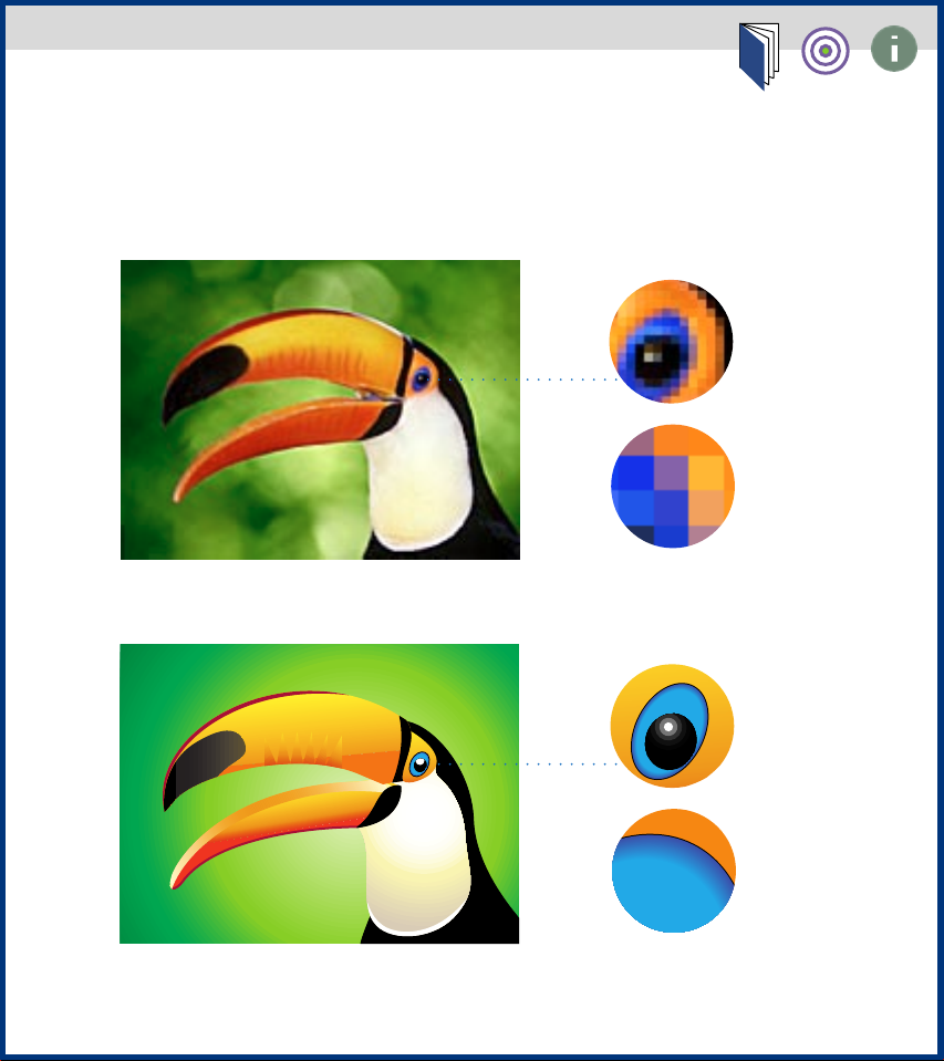
Bitmap vs. Vector graphics
Click on artwork to jump to information on that format.
Bitmap
4:1 zoom
16:1 zoom
4:1 zoom
Vector
16:1 zoom
Page 8

Opening documents
When you start Adobe Illustrator, the
program automatically opens a new
document. You can also create a new
document at any time, once Illustrator is
running. In either case, a new document
appears with the name
Untitled art
title bar.
You can open existing documents as
well as create new ones. An existing
document appears with its name displayed in the title bar.
in its
See also
To open a new document:
Opening and placing artwork.
Choose File > New from the Illustrator
menu bar.
To open an existing document:
Choose File > Open.
1
2
Select the name of the document you
want to open, and click Open.
Page 9

Saving documents
You can save a document under its
current name, location, and file format
by using the Save command. If you are
saving the document for the first time,
the Save dialog box appears, enabling
you to specify how and where you want
to save the document.
By using the Save As command, you can
save a copy of a document under a different name, location, or file format. For
information on saving a document in a
different file format or with a special
preview option, see Exporting artwork.
To save a file:
Choose File > Save or File > Save As.
1
If you choose the Save As command, or
if the document has not been saved
before, choose any of the following
options:
•
Select the folder in which you want to
save the document.
•
Create a new folder by clicking New.
•
Enter the name of the document in the
Save This Document As text box.
Page 10

•
From the Format pop-up menu,
choose the file format in which you
want to save the document.
2
If you save the document in EPS format, you can add Fetch® information.
Fetch
is a program that searches for and
retrieves files based on information
about the file. Choose any of the following options:
•
Select the Include Document Thumbnail option to create a thumbnail preview for the file when viewed by Fetch.
•
Enter the author’s name in the Author
text box.
•
Enter any search keywords, separated
by commas, in the Keywords text box.
•
Enter any identifying information
about the document in the Description
text box.
3
Click Save.
Page 11

Setting preferences
After you have used Illustrator for a
while, you may develop preferences for
the way in which various commands
and tools work in the program. To
accommodate different styles of working, Illustrator lets you set and save a
wide variety of preferences. Any time
you work in Illustrator, your saved preferences take effect, and tools and commands work the way you have specified.
To set preferences:
Choose File > Preferences and then
1
choose the type of preference you want
to change:
•
The General Preferences dialog box
contains preferences for how various
commands and tools work.
•
The Color Matching dialog box lets
you coordinate the colors displayed
by your monitor with the color system
you choose.
Page 12

•
The Hyphenation Options dialog box
defines which language dictionary is
used and lets you specify any words you
don’t want Illustrator to hyphenate.
•
The Plug-ins dialog box lets you
indicate where the plug-in modules
are located.
Page 13
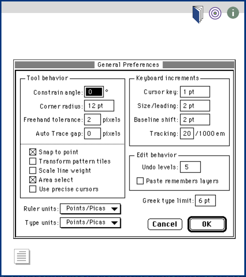
General Preferences dialog box
Click on any option for information on that option.
return to text
Page 14

Using the toolbox and the plug-ins
toolbox
The first time you open a document, the
toolbox appears on the left side of the
screen. The toolbox contains the set
of working tools with which you can
create, select, and manipulate objects
in Illustrator.
A further set of tools is available on the
plug-ins toolbox. This second toolbox
contains tools that can be provided by
third-party developers. For more information about plug-ins, see Using plug-in
modules.
To show or hide either toolbox:
Choose any of the following options:
•
Choose Windows > Show Toolbox to
display the standard tools.
•
Choose Windows > Show Plug-in Tools
to display the plug-in tools.
•
Choose Windows > Hide Toolbox to
hide the standard tools.
•
Choose Windows > Hide Plug-in Tools
to hide the plug-in tools.
Page 15

To move either toolbox:
Drag it by the title bar.
See also
•
Selecting tools
•
Using the tool pointers
•
Toolbox overview
Page 16
Using the tool pointers
Many of the tools change the mouse
pointer to an icon that indicates the
function of the selected tool. For example, choosing the brush tool changes
the pointer to a brush. You can also
change any painting or editing tool
pointer to a cross hair.
To change the pointer to a cross hair:
Choose one of the following options:
•
While the tool is selected, press the
Caps Lock key on the keyboard.
•
Choose File > Preferences > General,
select the Use Precise Cursors option,
and click OK.
jump to art
Page 17
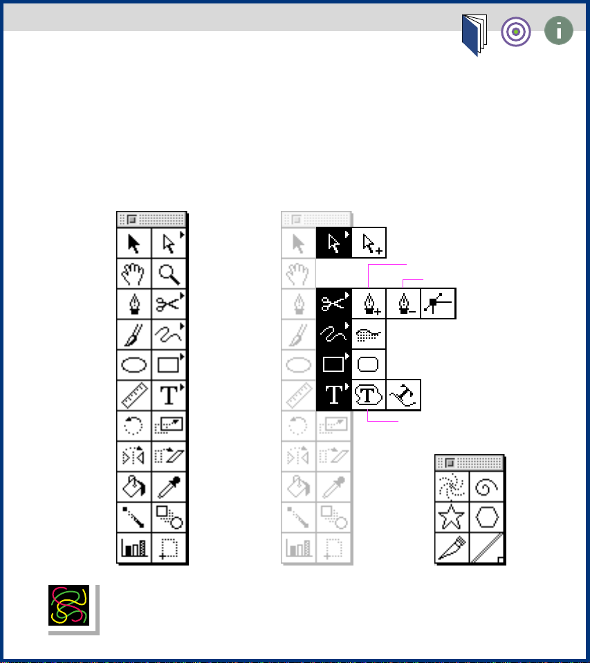
Selecting tools
Select a tool from the default toolbox by clicking the tool. Select
a hidden tool by positioning the pointer on the current tool in the
toolbox and dragging to highlight the tool.
Click on any tool to jump to information on that tool.
Selection
Hand
Pen
Brush
Oval
Measure
Rotate
Reflect
Paint Bucket
Gradient
Graph
Directselection
Zoom
Scissors
Freehand
Rectangle
Type
Scale
Shear
Eyedropper
Blend
Page
jump to art
Group-selection
Add-anchor point
Delete-anchor point
Convert-direction
point
Autotrace
Rounded-rectangle
Path-type
Area-type
Twirl
Star
Knife None
Spiral
Polygon
Page 18
Toolbox overview
Click on any artwork to jump to information on that tool.
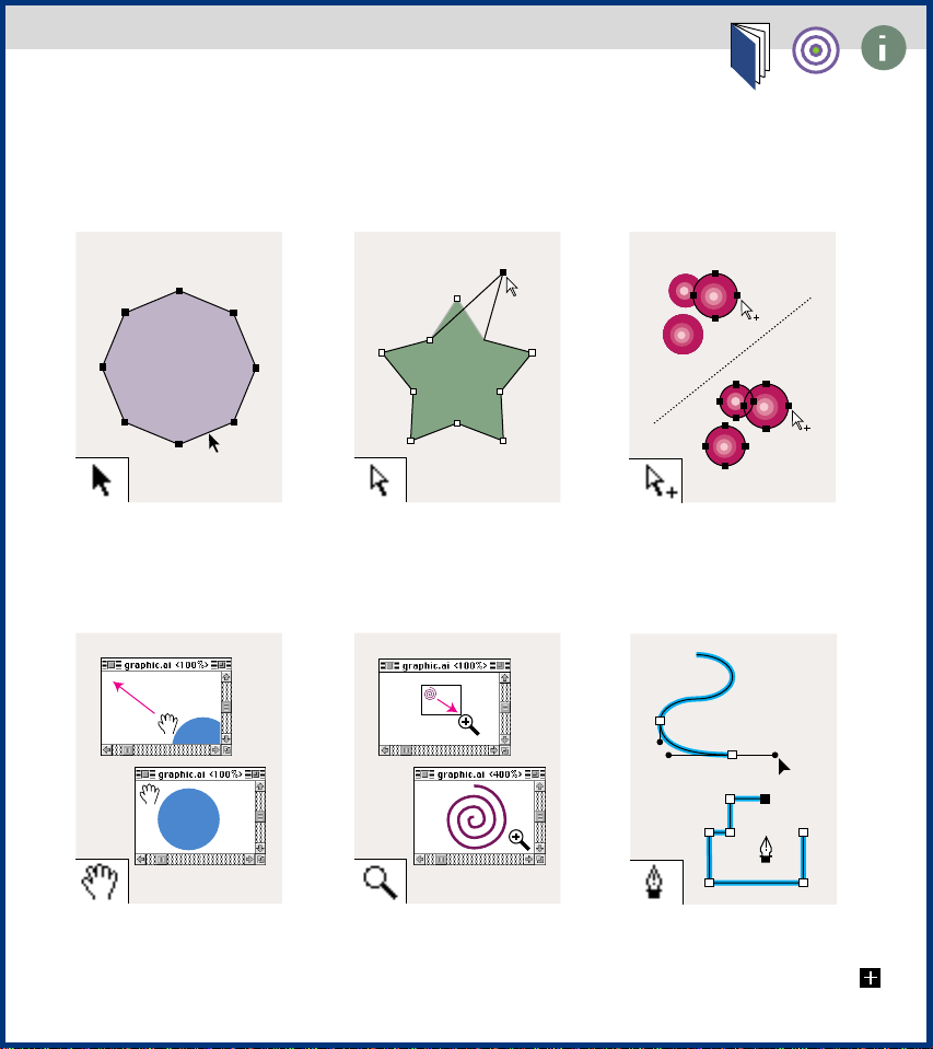
The selection tool
selects entire objects.
The hand tool moves the
Illustrator artboard within
the document window.
The direct-selection tool
selects points or segments
within objects.
The zoom tool increases
and decreases the view in
the document window.
The group-selection tool
selects objects and groups
within groups.
The pen tool draws
straight and curved
lines to create objects.
Page 19
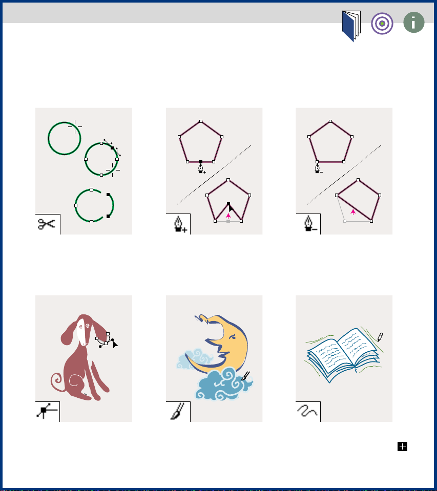
Toolbox overview, continued
Click on any artwork to jump to information on that tool.
The scissors tool splits
paths.
The convert-anchor-point
tool changes smooth
points to corner points
and vice versa
The add-anchor-point
tool adds anchor points
to paths.
The brush tool draws
freehand lines of
varying thickness.
The delete-anchor-point
tool deletes anchor points
from paths.
The freehand tool
draws freehand lines.
Page 20
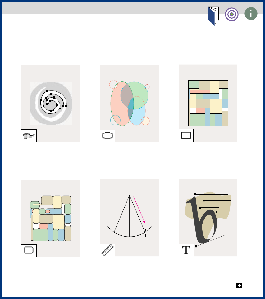
Toolbox overview, continued
Click on any artwork to jump to information on that tool.
The autotrace tool
traces the outline of
objects in a template.
The rounded rectangle
tool draws squares and
rectangles with rounded
corners.
The oval tool draws
circles and ovals.
The measure tool
measures the distance
between two points.
The rectangle tool
draws squares and
rectangles.
The beeboppers bellow the blues in
B-flat on the
the baritone
bassoon,
and bass
The type tool creates
individual type and type
containers and lets you
enter and edit type.
Page 21
Toolbox overview, continued
Click on any artwork to jump to information on that tool.
6
2
A
-
s
p
m
e
t
n
i
r
P
v
0
r
i
2
u
d
e
l
r
c
a
S
e
L
The area-type tool creates
individual type and type
containers and lets you
enter and edit type.
The scale tool resizes
objects around a fixed
point.
The path-type tool changes
paths to type paths, and
lets you enter and edit type
on a type path.
The reflect tool flips
objects over a fixed axis.
The rotate tool rotates
objects around a fixed
point.
The shear tool skews
objects around a fixed
point.
Page 22
Toolbox overview, continued
Click on any artwork to jump to information on that tool.
The eyedropper tool
samples paint attributes
from objects.
nstrument
The blend tool creates a
blend between the color
and shape of two objects.
The paint-bucket tool fills
objects with the current
paint attributes.
1994
1995
90
80
70
60
50
40
30
20
10
0
BA
The graph tool creates
graphs.
The gradient tool adjusts
the beginning and ending
points of gradients within
ojbects
The page tool adjusts
the page grid to control
where artwork appears
on the printed page.
Page 23
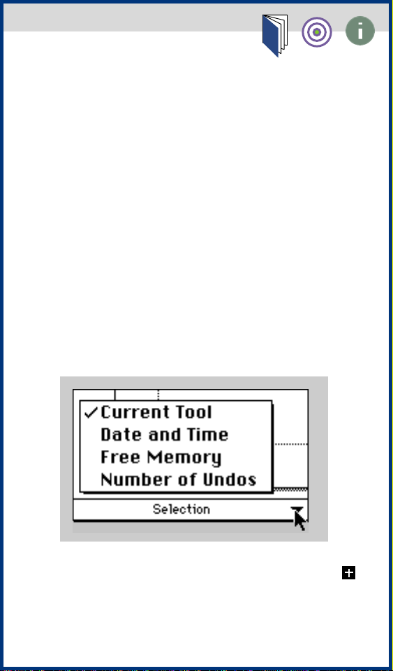
Using the status bar
A status line is displayed at the bottom
left edge of the Illustrator document
window. The status line can display
information about any of four different
topics:
• The current tool in use
• The time and date
• The amount of free memory (RAM)
available for your open document
• The number of undos and redos
available
Page 24

To specify the type of information you
want to display in the status line:
Position the cursor over the status
1
line bar and hold down the mouse
button.
2 Drag to choose the type of informa-
tion you want from the pop-up menu.
Page 25

Using the Shortcuts palette
The Shortcuts palette displays a brief
description of the function of all tools
and keyboard shortcuts available in
Illustrator.
To use the Shortcuts palette:
Choose Show Shortcuts from the Help
1
menu, located at the top right of the
menu bar.
2 Click Forward or Back to go forward
or backward one topic at a time.
Page 26

Correcting mistakes
You can use the Undo command to
correct mistakes you make while using
the Adobe Illustrator program. You can
even undo an operation after you have
chosen the Save command (but not if
you have closed and then reopened the
file). If an operation cannot be undone,
the Undo command is dimmed.
Depending on how much memory is
available, you can undo up to 200 of
the last operations you performed, in
reverse order, by repeatedly choosing
the Undo command. Illustrator’s performance is usually not affected by the
number of undo levels you choose;
however, if you are trying to display
complex artwork, you may receive a
message asking you to reduce the
number of undo levels because of
insufficient memory.
The default undo level is set at 10.
You can set the number of undo levels,
between 0 and 200, in the General
Preferences dialog box.
Page 27

To undo or redo an operation:
Choose Edit > Undo or Edit > Redo.
To change the maximum number of
undo levels:
Choose File > Preferences > General,
enter a value in the Undo Levels text
box, and click OK.
Page 28

Reverting to an earlier version of your
document
The Revert to Saved command restores
your document to the version that was
last saved. You cannot undo this action.
To revert your document to the saved
version:
Choose File > Revert to Saved.
Page 29
Using plug-in modules
A plug-in is a software module that adds
functions to the main program. A collection of plug-ins is installed in the Plugins folder within the Adobe Illustrator
6.0 folder. Third-party developers
also can create plug-in modules; see
Creating plug-in modules for Adobe
Illustrator for more information.
Plug-ins work the same way that other
functions in Illustrator work. In fact, in
most cases, you cannot even tell which
functions are part of the main Illustrator
program and which are plug-ins.
When you install Adobe Illustrator and
include plug-ins as part of the installation, these files are placed in the Plugins folder in the Adobe Illustrator folder.
If you change the location of these files
or of the Plug-ins folder, you must use
the Plug-ins preferences command to
tell Illustrator about the new location of
the plug-ins.
Page 30

You can also use plug-ins from version
3.0.4 or later of Adobe Photoshop, and
from Adobe Gallery Effects (included in
the Adobe Illustrator Deluxe CD-ROM
disc). In addition, you can use thirdparty plug-ins designed for Photoshop
or Illustrator. (Plug-ins designed for
Photoshop display a Photoshop icon
in the Illustrator menu.)
To install a plug-in module:
Drag the plug-in into the Adobe
Illustrator Plug-ins folder.
To specify the location of plug-in
modules:
Choose File > Preferences > Plug-ins.
1
2 Select the folder containing the plug-
in modules and click the Select button at
the bottom of the dialog box.
3 Quit Illustrator, and then start it again
for the plug-in modules to take effect.
Tip: Make an alias to your Photoshop
plug-in filters in your Illustrator Plug-ins
folder, so you don’t have to duplicate
your filters between the two programs.
Page 31

Creating plug-in modules for Adobe
Illustrator
The open architecture of the Adobe
Illustrator program allows third-party
developers to create features that are
accessible from within Adobe Illustrator.
If you are interested in creating plug-in
modules compatible with Adobe Illustrator, see the Adobe Systems Incorporated
Home Page at http://www.adobe.com.
You can also contact the Adobe Developers Association (ADA) by telephone. In
the United States, call (415) 961-4111; in
Europe, call +31-20-6511 275. In addition, you can reach the ADA by e-mail at
devsup-person@mv.us.adobe.com.
Page 32

Viewing and Setting Up
Documents
Viewing modes
Previewing and printing patterns
and placed EPS images
Moving the view of a document
Magnifying and reducing the view
Creating custom views
Displaying multiple views of a
document
Using rulers
About the work area
Changing the artboard size
Aligning the artboard with the
printed page
Choosing tiling options
Moving the page boundaries
Setting up standard and custom
pages
Page 33

Viewing modes
You have three views in which to display
your artwork on-screen: Preview view
(the default), Artwork view, and Preview
Selection view.
Preview view Preview Selection view
Artwork view
Page 34

To change the view:
Choose one of the following options:
• Choose View > Preview to view the
artwork as it will be printed, filled with
as many colors and as much shading
and detail as your monitor is capable of
displaying. Preview view is the default
view when you open a new document,
and the most used view because it best
indicates what the finished artwork will
look like.
• Choose View > Artwork to view
objects in the artwork as wireframe
outlines, hiding the paint attributes
of the objects. Working in this view
can speed up the display when you
are editing complex artwork (such as
objects containing gradients or patterns)
that requires a long time to redraw
on-screen. Artwork view can also make
editing easier, because in this view
objects are not easily hidden by other
filled objects overlapping them.
Page 35

Note: You can use the Artwork View
Speedup filter to speed up redrawing
and editing in Artwork view. All artwork
handles are displayed in black while
editing in Artwork View with the Artwork
View Speedup filter in effect. To use the
Artwork View Speedup filter, place it into
Illustrator’s Plug-ins folder and restart
Illustrator. This filter does not appear on
the menu, it is in effect whenever you
are in Artwork view.
• Choose View > Preview Selection to
view selected objects in Preview view
and display unselected objects in
Artwork view. Selecting other objects in
Preview Selection view displays the
newly selected objects with their paint
attributes visible. This view is useful for
speeding the artwork display when you
want to view the objects you are editing
as they will look when printed.
Page 36

Previewing and printing patterns and
placed EPS images
Placed EPS images from other applications and objects that are filled with
patterns can slow performance when
previewing and printing artwork.
The Show Placed Images option in the
Document Setup dialog box lets you
choose whether placed EPS images
display a 1-bit preview when seen
in Artwork view. (For information on
placed images, see Opening and placing
artwork.)
The Preview and Print Patterns option in
the Document Setup dialog box lets you
specify whether patterns appear in your
artwork when you preview or print your
illustration. For information on patterns,
see About custom colors, gradients, and
patterns.
These options are on by default. Turn off
these options when you need to work
quickly—for example, when you are
editing nonpatterned parts of the artwork. You can then turn these options
back on when you want to view the
finished art.
Page 37

To determine how placed EPS images
and patterns appear:
Choose File > Document Setup.
1
2 Choose any of the following options:
• Select or deselect the Show Placed
Images option.
• Select or deselect the Preview and
Print Patterns option.
3 Click OK.
Page 38

Moving the view of a document
You can view different areas of a document using the scroll bars or the hand
tool.
Moving the hand tool around on an Illustrator document is analogous to moving
a piece of paper on a desk with your
hand.
To scroll with the hand tool:
Select the hand tool.
1
2 Move the pointer onto the document
and drag in the direction in which you
want the document to move.
Tip: To scroll quickly with the hand tool
while using another tool, hold down the
spacebar and drag with the mouse.
Page 39

Magnifying and reducing the view
The zoom-in and zoom-out tools and
commands magnify or reduce the display of any area in the document up to
16 times. Zooming in and out changes
only the magnification at which you see
the document, not its actual size. (For
more on resizing objects, see Scaling.)
Two other commands provide shortcuts
to often-used magnification levels. The
Actual Size command lets you display a
document at 100% magnification, and
centers the document in the active window. The Fit In Window command centers and scales the artboard so that it
fits within the active window.
The current magnification level is
displayed at the top of the document
window.
To zoom in:
Choose one of the following options:
• Select the zoom tool (the pointer
becomes a magnifying glass with a plus
sign in its center) and click at the center
of the area you want to magnify.
Page 40

Continue clicking until the document is
magnified as desired. When the document has reached its maximum magnification level of 1600%, the magnifying
glass appears blank.
• Choose View > Zoom In. Continue
choosing this option until the document
is magnified as desired. When the document has reached its maximum magnification level of 1600%, the command is
dimmed.
Tip: To choose the zoom-in tool while
using another tool, press Command+
spacebar. To chose the zoom-out tool
while using another tool, press
Command+ Option+spacebar.
To zoom out:
Choose one of the following options:
• Select the zoom tool while holding
down the Option key (the pointer
becomes a magnifying glass with a
minus sign in its center), and click at the
center of the area you want to reduce.
Continue clicking until the document is
magnified as desired. At the document’s
maximum reduction level of 6.25%, the
magnifying glass appears blank.
Page 41

• Choose View > Zoom Out. Continue
choosing this option until the document
is magnified as desired. When the document reaches its maximum reduction
level of 6.25%, the command is dimmed.
To magnify by dragging:
Select the zoom-in tool.
1
2 Drag to draw a dotted rectangle,
called a marquee, around the area you
want to magnify. To draw the marquee
from the center, hold down the Control
key as you drag. To move the marquee
around the artwork, begin dragging a
marquee, and then hold down the spacebar while dragging the marquee to a
new location.
3 Release the mouse button.
To display a document at 100%:
Choose View > Actual Size, or doubleclick the zoom tool.
To scale the artboard to fit the window:
Choose View > Fit In Window, or doubleclick the hand tool.
Page 42
Creating custom views
You may want to switch between several views while working on an Illustrator document. For example, you may
want to set one view highly magnified
for doing close-up work on some
objects and create another view not as
magnified for laying out those objects
on the page. You can create and store up
to 25 views of a document. When you
save a view, the current zoom level,
scroll position, layer options, and view
(that is, Artwork, Preview, or Preview
Selection) settings are retained and
named so that you can call up the same
view at any time.
200%, Preview view 400%, Preview view
Page 43

To create a new view:
Set up the view that you want.
1
2 Choose View > New View.
3 Enter a name for the new view, and
click OK.
The view names, along with keyboard
shortcuts for accessing them, appear
at the bottom of the View menu. To
retrieve a view, select the name of the
view you want to use.
To rename or delete a view:
Choose View > Edit Views.
1
2 Select the view you want to edit and
rename it or click Delete.
Page 44

Displaying multiple views of a
document
You can display several views of the
same document in separate windows.
For example, you can simultaneously
view several magnification levels of one
drawing. Because the windows are simply different views of the same document, editing artwork in any of the windows affects the artwork in all windows
at the same time.
To open a new window:
Choose Window > New Window.
A new window of the same size appears
on top of the previously active window.
The two windows are identical except
for their window numbers. The title bar
in the new window is highlighted, indicating that it is the active window.
Tip: Use the New Window command to
preview in one window while editing in
Artwork view in another.
Page 45

Using rulers
Illustrator can display rulers, one along
the bottom and one along the right side
of the document window.
When you open a new document, the
rulers are not visible, but you can display them at any time. These rulers are
a tool for placing and measuring objects
in artwork accurately. As you scroll and
zoom around the document, the rulers
adjust accordingly.
To show or hide rulers:
Choose View > Show Rulers or View >
Hide Rulers.
See also
• Defining ruler units
• Automatically converting unit
values in text boxes
• Changing the ruler origin
Page 46

Defining ruler units
The large tick marks on the rulers indicate the unit of measure (such as
inches), and the small tick marks indicate increments of the unit of measure
(such as 1/8 inch). When you magnify or
reduce the document view, the increments of the unit of measure reflect the
change in magnification.
The default units of measure for the rulers are points and picas. A point equals
1/72 of an inch; a pica equals 12 points,
or 1/6 of an inch. You can change the
unit of measure to inches or millimeters
using the General Preferences dialog
box or the Document Setup dialog box.
The unit of measure that you set for
the rulers applies when you measure
objects, move and transform objects,
and create ovals and rectangles. It does
not affect the units in the Character,
Paragraph, and Paint Style palettes,
which always display size, leading, vertical shift, line width, and line dash in
points. (See Setting type attributes for
more information on units of measure
for type.)
Page 47

To set the unit of measure:
Choose one of two options:
1
• To change the unit of measure for
all documents, choose File > General
Preferences.
• To change the unit of measure for the
active document only, choose File >
Document Setup.
2 From the Ruler Units pop-up menu,
drag to specify the unit of measure you
want to use.
3 Click OK.
Page 48

Automatically converting unit values
in text boxes
If you use other than the preset unit to
enter values, Illustrator converts it to
the set unit. For example, entering “3
cm” in a text box set to inches converts
the value to 1.181 inches.
You can also add, subtract, multiply,
divide, and perform other mathematical
operations in any Illustrator text box
that accepts numeric values. Illustrator
performs the calculation and uses the
result.
For example, when specifying the size
of a rectangle, you can type “72 pt +
2 pt” for the height. When you enter a
value in a text box, you must indicate
the units after each value (for example,
mm for millimeters, pt for points, and in
for inches).
Parentheses are also allowed in expressions, and units can be added onto the
resulting expression, as in “(4 + 5) in”.
Also, expressions can be arbitrarily
complex, such as “((4 + 5) / 2) in +
16 in”.
Page 49

Changing the ruler origin
The point where 0 appears on each ruler
is called the ruler origin. When you open
a document, the position of the ruler origin depends on the View option selected
in the Document Setup dialog box. Generally, if you have selected either the
Single Full Page or the Tile Full Pages
option, the default ruler origin is located
at the lower left corner of page 1.
When you change the ruler setting, the
new setting becomes the default for the
document whenever that document is
opened. You can change the origin for
the rulers at any time. For example, you
may be working on a 3-inch-by-5-inch
card that is centered on an 8.5-inch-by11-inch page. Setting the ruler origin to
line up with the 3-by-5-inch artwork
rather than the 8.5-by-11-inch page can
make precision editing easier for you.
Note: The position of the ruler origin
affects the tiling of patterns, as well as
the bounding box information for the
Separation Setup command. For more
information about the bounding box,
see Specifying the bounding box in the
separation.
Page 50

To change the ruler origin:
Move the pointer to the lower right
1
corner of the rulers where the rulers
intersect.
2
Drag the pointer to where you want
the new ruler origin. As you drag, a
cross hair in the window and in the rulers indicates the changing ruler origin.
3
Release the mouse button to set the
new 0,0 point in the rulers.
16
8
0
160 88
Page 51

About the work area
In Adobe Illustrator, the work area
occupies the entire space within the
Illustrator document window, and
includes more than just the printable
page containing your artwork. The work
area is made up of four sections:
• Imageable area
• Nonimageable area
• Artboard
• Scratch area
jump to art
Page 52

Imageable area
The imageable area is the area within
the dotted lines representing the
portion of the page on which the
selected printer can print an image.
Many printers cannot print to the
edge of the paper.
jump to art
Page 53

Nonimageable area
The nonimageable area is the area
between the dotted and solid lines
representing any nonprintable margin
of the page. This example shows the
nonimageable area of an 8.5" x 11" page
for a standard laser printer.
jump to art
Page 54

Artboard
The artboard is the area within the solid
lines representing the region that can
contain printable artwork. The artboard
equals the imageable area plus any nonimageable area. By default, the artboard
is the same size as the page, but it can
be enlarged, as in the example shown.
The U.S. default artboard is 8.5" x 11",
but can be set as large as 120" x 120".
jump to art
Page 55

Scratch area
The scratch area is the area between
the solid lines, and the border of the
document window represents a space
on which you can create, edit, and store
elements of artwork before moving
them onto the artboard. Objects placed
on the scratch area are visible on-screen,
but they do not print.
jump to art
Page 56

The work area
Click on any option for information on that option.
Imageable
area
Nonimageable
area
Artboard
Scratch area
return to text
Page 57

Changing the artboard size
The boundaries of the artboard define
the maximum printable area of your
document. By default, the artboard is
U.S. letter size (8.5 inches by 11 inches).
You can change the artboard’s dimensions using the Document Setup dialog
box.
To change the size of the artboard:
Choose File > Document Setup.
1
2 Choose any of the following options:
• Choose a preset size from the Size
pop-up menu.
• Choose Custom from the Size pop-up
menu, and enter the dimensions you
want in the Dimensions text boxes, up
to 120 inches by 120 inches. You can
change the units of the artboard size by
choosing a different ruler unit size from
the Ruler Units pop-up menu.
Page 58

• Select the Use Page Setup option to
set the size of the artboard to match the
page size set in the Page Setup dialog
box. The size of the artboard then
changes any time you choose a new
page size in the Page Setup dialog box.
3 Click OK.
jump to art
See also
• About the work area
• Setting up standard and custom
pages
• Document Setup dialog box
Page 59

Aligning the artboard with the
printed page
The artboard’s dimensions do not necessarily match the paper sizes used by
printers. As a result, when you print a
document, the program divides the artboard into one or more rectangles that
correspond to the page size available on
your printer. Dividing the artboard to fit
a printer’s available page size is called
tiling.
You define the page size by selecting a
page type in the Page Setup dialog box.
On most printers, the imageable area
is slightly smaller than the page. The
imageable area is surrounded by either
dotted lines or a gray rectangle. (This
area is usually centered on the artboard
by default; however, if an inkjet printer
is selected, the imageable area may
be displayed to the left and top of the
artboard.)
Note: The imageable area and page size
is not a limitation when printing to
imagesetters that handle large media.
Imagesetters can typically print to the
edge of the page. The page size used by
an imagesetter may be larger than
Page 60

the page size specified in Illustrator,
enabling you to print bleeds, for
example, that run past the edge of
the page.
As you work with tiled artwork, be sure
to consider how the artwork relates to
the boundaries of the page grid and to
the total dimensions of the artboard. For
example, if the artwork is tiled onto six
pages, part of the artwork will print on
a separate sheet of paper that corresponds to page 6. If you specify printing
only from pages 1 to 5, the part of the
artwork that is on page 6 won’t print.
The program may print blank pages if
the document is tiled so that the bounding box of the artwork intersects pages
that do not contain any artwork. The
bounding box is a transparent border
that defines the boundaries of your artwork. In the following illustration, the
bounding box surrounds the artwork,
not its direction lines.
See also
• About the work area
• Setting up standard and custom
pages
Page 61

Choosing tiling options
You set how pages tile using the options
in the Document Setup dialog box—
Single Full Page, Tile Full Pages, and Tile
Imageable Areas. These options let you
print the artwork on one or more pages,
printing each page according to the
page size defined in the Page Setup
dialog box.
To set whether the tiling format is
visible on-screen:
Choose View > Show Page Tiling or
View > Hide Tiling.
To change the page tiling options:
Choose File > Document Setup.
1
2 Choose one of the following options:
jump to art
• Select the Single Full Page option (the
default) to view and print one page.
Page 62

• Select the Tile Full Pages option to
view and print multiple pages containing
separate pieces of artwork. For example,
you can use this option to print a twopage brochure.
To view and print multiple pages, the
artboard size set in the must be large
enough to fit more than one full page at
a time.
Note: With the Tile Full Pages option,
any artwork that extends past the
imageable area of a given page is not
printed.
• Select the Tile Imageable Areas option
to view and print a single piece of
artwork that is too large to fit on one
page. For example, you could use this
option to print artwork for a large poster
onto several sheets of standard-size
paper for proofing.
When you print a document using this
option, the artwork is divided among
the imageable areas of the pages.
3 Click OK.
Page 63

If you have set up the document to view
and print multiple pages, the document
is tiled onto pages numbered from left
to right and from top to bottom, starting
with page 1. These page numbers
appear on-screen for your reference
only; they do not print. The numbers
enable you to print all of the pages in
the document or specify particular
pages to print.
The page or set of pages is aligned with
the center of the artboard by default.
However, you can reposition pages on
the artboard using the page tool, as
described next in moving the page
boundaries.
See also
• About the work area
• Setting up standard and custom
pages
• Document Setup dialog box
Page 64

Tiling options
Single Page option:
Letter size page
11” x 14” artboard
Tile Full Pages option: Letter size page
20”x 14” artboard
Page 65

Tile Imageable Areas
option: Letter size page
40”x 60” artboard
Page 66

Moving the page boundaries
You can adjust the placement of a page
on the artboard to control how artwork
is printed on the page. This is a good
way to avoid having the artwork extend
past the boundaries of the current page.
You can adjust the page on any of the
three View displays. You may find it easier to choose View > Fit In Window first
so that you can see more of the document while you adjust the pages.
Note: When you set up your page, you
can set the page size so that all of the
artwork fits on one page, as described in
Changing the artboard size.
Drag the page . . . to the new location.
Page 67

See also About the work area
To adjust a page using the page tool:
Select the page tool. The pointer is a
1
dotted cross in the active window.
2 Drag the page to the new location. As
you drag, two gray rectangles appear:
the outer rectangle indicates the page
size, and the inner rectangle indicates
the page’s printable area.
Note: To move a page past the artboard
boundary, change the artboard’s size in
the Document Setup dialog box. Any
part of a page that extends past the
artboard boundary is not displayed or
printed.
To adjust the artwork placement by
moving it:
Unlock any locked objects and
1
display any hidden objects. (See Locking
and hiding objects, Locking layers, and
Hiding and showing layers.)
2 Choose the selection tool.
3 Choose Edit > Select All.
4 Drag the artwork to the new position
within the page boundaries.
Page 68

Setting up standard and custom pages
Using the Document Setup dialog box (to set the artboard size and
page tiling) with the Page Setup dialog box (to set different page sizes
and orientations) lets you create standard- and custom-size pages.
Select the Use Page Setup option in the Document Setup dialog box to
override the dimensions set in the Document Setup dialog box. If you
have artwork with bleeds, making the artboard larger than the page
leaves room for crop marks, trim marks, and registration marks.
Vertical letter page
Document Setup:
•
Use Page Setup
Page Setup:
•
US letter paper
•
Portrait orientation
Page 69

Setting up standard and custom pages
Horizontal letter page
Document Setup:
• Use Page Setup
Page Setup:
• US letter paper
• Landscape orientation
return to text
Page 70

Setting up standard and custom pages, continued
Vertical tabloid page
Document Setup:
• Use Page Setup
Page Setup:
• Tabloid paper
• Portrait orientation
return to text
Page 71

Setting up standard and custom pages, continued
Horizontal tabloid page
Document Setup:
• Use Page Setup
Page Setup:
• Tabloid paper
• Landscape orientation
return to text
Page 72

Setting up standard and custom pages, continued
Two-page spread
return to text
Document Setup:
• Custom artboard
(19.5" by 13.5")
• Landscape orientation
• Tile Full Pages view
Page Setup:
• US letter paper
• Portrait orientation
Page 73

Setting up standard and custom pages, continued
Standard envelope – center fed
Document Setup:
• Use Page Setup
Page Setup:
• Envelope paper
• Landscape orientation
return to text
Page 74

Setting up standard and custom pages, continued
US letter page with bleed
Document Setup:
• Tabloid paper
• Portrait orientation
• Single Full Page view
Page Setup:
return to text
• US letter paper
• Portrait orientation
Page 75

Setting up standard and custom pages, continued
Custom page
Document setup:
• Custom artboard
(22.75" by 25.3375")
• Portrait orientation
• Tile Imageable Areas
Page Setup:
• US letter paper
• Landscape orientation
return to text
Page 76

Document Setup dialog box
Click on any option for information on that option.
return to text
Page 77

Drawing
About paths and anchor points
Drawing with the freehand tool
Drawing with the pen tool
Selecting objects
Adjusting path segments
Hiding the anchor points and edges
of a selected object
Adding and deleting anchor points
Selecting stray points
Splitting paths with the scissors tool
Averaging anchor points
Joining endpoints
Drawing with the brush tool
Adding calligraphic strokes to
objects
Drawing rectangles and ovals
Page 78

Drawing, continued
Drawing polygons
Drawing spirals
Drawing stars
Tracing artwork
Page 79

About paths and anchor points
A path is any line or shape that you create using the Adobe Illustrator drawing
tools, and represents the outline of a
graphic object. A single straight line, a
rectangle, and the outline of a map are
all typical examples of paths.
A path consists of one or more segments. Anchor points, which define
where each segment of a path starts and
ends, “anchor” the path in place. By
moving anchor points, you modify path
segments, and change the shape of a
path.
A path can be either open or closed. A
closed path is a path that is continuous
and has no beginning or end (and therefore, no endpoints); a circle is an example of a closed path. An open path has
distinct endpoints; a wavy line, for
example, is an open path.
Page 80

The first and last anchor points on an
open path are called the endpoints.
If you fill an open path, the program
draws an imaginary line between the
two endpoints and fills the path.
Selected line
segment
Unselected
anchor point
Closed paths
Selected
endpoint
Open paths
Selected
anchor point
Page 81

Drawing with the freehand tool
The freehand tool lets you draw paths
as if you were using a pencil. You can
use it for fast sketching or creating a
more handdrawn look than you could
with the pen tool.
The freehand tool sets anchor points as
you draw, according to the path length
and complexity, and the Freehand Tolerance value (2 pixels, by default) set in
the General Preferences dialog box. You
can adjust the position of anchor points
after completing the path. The freehand
tolerance controls the sensitivity of the
tool when you move the mouse or
graphics-tablet stylus; the higher the
tolerance, the less complex and
smoother the path.
210
Freehand tolerance settings
Page 82

To draw a freehand path:
Select the freehand tool.
1
2 Position the pointer where you want
the path to begin, and drag. (If the Use
Precise Cursors option is select in the
General Preferences dialog box, the
pointer appears as a cross hair.)
As you drag, a dotted line trails the
pointer. When you release the mouse
button, anchor points appear along the
path and at its ends. The path takes
on the current paint attributes, and is
selected.
Drag to draw Result
3 To continue the existing freehand
path, position the pencil tip precisely on
an endpoint of the path (the pencil’s
eraser will turn black) and drag.
Page 83

To erase part of the path as you draw:
Hold down the Command key and drag
back over the path. As you drag, the
pointer changes to an eraser.
To set the freehand tolerance:
Choose File > Preferences > General.
1
2 Enter a value between 0 and 10 in the
Freehand Tolerance text box. Click OK.
To make drawing tool pointers
cross hairs:
Choose File > Preferences > General.
1
2 Choose the Use Precise Cursors
option, and click OK.
Page 84

Drawing with the pen tool
The pen tool lets you create straight
lines and smooth, flowing curves with
greater precision than with the freehand
tool. For most users, it is the most
important and powerful drawing tool in
Illustrator, as it provides the best control
and greatest accuracy for drawing.
See also
•
Drawing straight lines
•
About direction lines and direction
points
•
Drawing curves
•
About ink pen effects
Page 85

Drawing straight lines
The simplest line you can draw with the
pen tool is a straight line, by clicking the
pen tool to create anchor points.
To draw straight lines with the pen tool:
Select the pen tool.
1
2 Move the tip of the pen to the straight
line’s starting point, and click. A solid
square, an anchor point, appears; it is
selected until you define the next point.
3 Click where you want the segment to
end. Hold down the Shift key to constrain
the tool to multiples of 45 degrees.
4 Keep clicking to draw more lines.
Drawing the first line Drawing more lines
Page 86

The last anchor point added is a solid
square, showing it is selected. The other
anchor points become hollow squares.
To end an open path:
Choose one of the following options:
• Click the pen tool in the toolbox.
• Hold down the Command key to
change to the selection tool, and then
click anywhere away from the path.
• Choose Edit > Select None.
• Select another tool.
To close a path:
Position the pen over the first anchor
point (a closed circle should appear next
to the pen tip), and click.
Page 87

About direction lines and direction
points
On curved segments, each selected
anchor point displays one or two
direction lines, ending in direction
points. The position of each direction
line and point determine the size and
shape of a curved segment. Moving
these elements reshapes the curves in
a path.
Direction point
Curved
segment
Parts of a curved segment
The direction lines are always tangent
to (touching) the curve at the anchor
points. The slope of each direction line
Direction line
Anchor
point
Page 88

determines the slope of the curve, while
the length of each direction line determines the height, or depth, of the curve.
Moving direction lines changes the slope
of the curve.
Continuous curved paths—paths along
a continuous wave shape—are connected by anchor points called smooth
points. Noncontinuous curved paths are
connected by corner points.
Smooth point Corner point
Page 89

When you move a direction line on a
smooth point, the curves on both sides
of the point adjust simultaneously. In
comparison, when you move a direction
line on a corner point, only the curve on
the same side of the point as the direction line is adjusted.
Adjusting smooth Adjusting corner
point point
Page 90

Drawing curves
You create curves by dragging the pen
tool in the direction you want the curve
to go. The following instructions explain
how to draw curves. See also About
direction lines and direction points.
To draw a curved path:
Select the pen tool.
1
2 Position the pen tip where you want
the curve to begin. Hold down the
mouse button. The first anchor point
appears, and the pen tip changes to an
arrowhead.
3 Drag in the direction you want the
curve segment to be drawn. As you
drag, the pointer leads one of two direction points.
The length and slope of the direction
line determine the shape of the curve.
You can adjust one or both sides of the
direction line later.
Page 91

4
Position the pointer where you
want the curve segment to end, press
the mouse button, and drag in the
opposite direction to complete the
segment. Hold down the Shift key
to constrain the tool to multiples of
45 degrees.
Drag in direction and then drag in
of curve to set opposite direction
anchor point . . . to complete curve.
Page 92

5 Choose one of the following options:
• To draw the next segment of a contin-
uous curve, position the pointer where
you want the next segment to end, and
drag away from the curve.
Drag away from curve to create next
segment.
• To change the direction of the curve
and create a noncontinuous curve,
position the pointer on the last anchor
point, hold down the Option key, and
hold down the mouse button to set a
corner point; then drag in the direction
of the curve. Release the Option key
Page 93

and mouse button, reposition the
pointer, and drag in the opposite
direction to end the curve segment.
Press Option key and drag in direction
of curve . . .
and then release Option key and drag
in opposite direction.
Page 94

Keep the following guidelines in mind to
help you draw any kind of curve quickly
and easily:
• Always drag the first direction point
in the direction of the bump of the
curve, and drag the second direction
point in the opposite direction to create
a single curve. Dragging both direction
points in the same direction creates an
“S” curve.
Drag in opposite Drag in same direction
direction to create to create S” curve.
smooth curve.
• When drawing a series of continuous
curves, draw one curve at a time, setting
anchor points at the beginning and end
of each curve, not at the tip of the
Page 95

curve. Use as few anchor points as
possible, placing them as far apart
as possible.
Less to more efficient curves
See the Adobe Illustrator Tutorial and
Beyond the Basics for step-by-step
procedures on drawing curves with
the pen tool.
Page 96

Selecting objects
Before you can modify an object, you
need to distinguish it from the objects
around it. You do that by selecting the
object with one of the selection tools.
Once you’ve selected an object, or a part
of an object, you can edit it by moving
or copying, deleting, or adjusting paths.
You select objects with one of three
selection tools:
• The selection tool lets you select
entire objects or an entire path by
selecting any spot on the path.
• The direct-selection tool lets you
select individual anchor points or
segments on a path and displays all
direction lines on a path for adjusting.
• The group-selection tool lets you
select groups of objects by clicking any
object in the group. Each additional click
adds the next objects in the grouping
hierarchy to the selection. See Grouping
and ungrouping objects for more
information.
Page 97

Tip: To use the last selection tool used
while using any other tool, hold down
the Command key.
To select an entire object or line:
Choose the selection tool or the
1
group-selection tool.
2 Choose one of the following options:
• If the object is filled, and you are in
Preview view, click within the object.
Note: The Area Select option in the
General Preferences dialog box must be
selected for this option to work. For
more information, see Selecting filled
objects.
• Click the path of the object.
• Click an anchor point of the object.
• Hold down the mouse button, and
drag a dotted rectangle, called a
selection marquee, around part or all
of the object.
Page 98

To select a segment:
Choose the direct-selection tool, and
then choose one of the following options:
• Click within 2 pixels of the segment.
• Hold down the mouse button, and
drag a selection marquee over part of
the segment.
Drag direct-selection to select segment and
marquee . . . display direction lines.
When you select a segment, all of the
anchor points on the path are displayed,
including any direction lines and direction points if the selected segment is
curved. Direction points appear as filled
circles; selected anchor points appear as
filled squares; unselected anchor points
appear as hollow squares.
Page 99

To add or remove selections:
Hold down the Shift key while selecting
additional objects or segments.
See also
• Selecting filled objects
• Selecting multiple objects
• Deselecting objects
Page 100

Selecting filled objects
The Area Select option in the General
Preferences dialog box controls whether
you can select a filled object in Preview
view by clicking anywhere within its area
or whether you must click a path or
anchor point. The Area Select option is
on by default.
 Loading...