

M
T
®
®
y
b
UP
DOWN
RIGHT
LEFT
CP9110
TM
Table of Contents
FULL ONE (1) YEAR WARRANTY
Actron Manufacturing Company, 15825 Industrial
Parkway, Cleveland, Ohio 44135, warrants to the
user that this unit will be free from defects in
materials and workmanship for a period of two (2)
years from the date of original purchase.
Any unit that fails within this period will be repaired
or replaced at Actron’s option and without charge
when returned to the Factory. Actron requests that
a copy of the original, dated sales receipt be
returned with the unit to determine if the warranty
period is still in effect.
This warranty does not apply to damages caused
by accident, alterations, or improper or unreasonable use.
ACTRON MANUFACTURING COMPANY DISCLAIMS ANY LIABILITY FOR INCIDENTAL OR
CONSEQUENTIAL DAMAGES FOR BREACH OF
ANY WRITTEN WARRANTY ON THE UNIT.
15825 Industrial Parkway
Cleveland, Ohio 44135
U.S.A.
Toll free U.S.: (800) 228-7667
©2004 Actron Manufacturing Co.
All Rights Reserved.
0002-002-2186
Vehicle Service Information ............. 2
Safety Precautions ............................ 3
Section 1:
Welcome to The Scan Tool ..
1-1 Features ........................................ 4
1-2 The scan tool................................. 5
1-3 What You Get................................ 6
1-4 Cartridge and Installation ..............6
1-5 Cables and Adapters.....................7
1-6 Operating the scan tool ................. 9
• Powering-up the scan tool ....... 9
• Keyboard .................................. 9
• Display.................................... 10
• Lists, Menus, & Questions ..... 10
• Other Functions & Keys ......... 11
1-7 Scan Tool Setup..........................12
Section 2:
Computer Vehicle Basics..
2-1 Basics of Computer-
Controlled Cars ........................ 13
2-2 About Codes................................16
2-3 When to Read Codes.................. 17
13
Section 3:
Help and Troubleshooting
Tips....................................19
3-1 Tool Problems ............................. 19
4
3-2 Car Problems ..............................20
3-3 Scan Tool Self-Tests................... 20
• Display Test ........................... 21
• Keyboard Test........................ 21
• Memory Test .......................... 21
Section 4:
How to Order
Accessories ......................22
4-1 Where to Buy?.............................22
4-2 Call Actron Direct ........................ 23
4-3 E-Mail & Internet address ........... 23
Section 5:
Appendix ...........................24
Glossary of Terms ............................. 24
30
1

Vehicle Service Information
The following is a list of publishers who have manuals containing electronic engine control
diagnostic information. Some manuals may be available at auto parts stores or your local
public library. For others, you need to write for availability and pricing, specifying the
make, model and year of your vehicle.
Vehicle Service Manuals:
Chilton Book Company
Chilton Way
Radnor, PA 19089
Haynes Publications
861 Lawrence Drive
Newbury Park, CA 91320
Cordura Publications
Mitchell Manuals, Inc.
Post Office Box 26260
San Diego, CA 92126
Motor’s Auto Repair Manual
Hearst Company
250 W. 55th Street
New York, NY 10019
Suitable manuals have titles such as:
“Electronic Engine Controls”
“Fuel Injection and Feedback Carbure-
tors”
“Fuel Injection and Electronic Engine
Controls”
“Emissions Control Manual”
. . . or similar titles
Vehicle Service Manuals from
General Motors Corporation:
Buick, Cadillac, Chevrolet, GEO, GMC,
Oldsmobile, & Pontiac
Helm Incorporated
Post Office Box 07130
Detroit, MI 48207
Saturn
Adistra Corporation
c/o Saturn Publications
101 Union St.
Post Office Box 1000
Plymouth, MI 48170
Vehicle Service Manuals from
Ford Motor Company:
Ford, Lincoln, & Mercury
Ford Publication Department
Helm Incorporated
Post Office Box 07150
Detroit, MI 48207
Vehicle Service Manuals from
Chrysler Corporation:
Chrysler, Plymouth, & Dodge
Chrysler Motors Service Training
26001 Lawrence Avenue
Center Line, MI 48015
General Safety Guidelines to Follow
When Working on Vehicles
To prevent accidents that could result in serious injury and/or damage
to your vehicle or test equipment, carefully follow these safety rules
and test procedures at all times when working on vehicles:
• Always wear approved eye protection.
• Always operate the vehicle in a
well-ventilated area. Do not inhale
exhaust gases — they are very
poisonous!
• Always keep yourself, tools and test
equipment away from all moving or
hot engine parts.
• Always make sure the vehicle is in
Park (Automatic transmission) or
neutral (manual transmission) and
that the parking brake is firmly
set. Block the drive wheels.
• Never lay tools on vehicle battery.
You may short the terminals together causing harm to yourself,
the tools or the battery.
• Never use scan tool if its internal
circuitry has been exposed to any
liquids. This includes the scan tool
and Application Cartridges.
• Never smoke or have open flames
near vehicle. Vapors from gasoline
and charging battery are highly flammable and explosive.
• Never leave vehicle unattended
while running tests.
• Always keep a fire extinguisher suitable for gasoline/electrical/chemical fires handy.
• Always use extreme caution when
working around the ignition coil, distributor cap, ignition wires, and spark
plugs. These components contain
high voltage when the engine is
running.
• When performing a road test, never
operate the scan tool alone while
driving the vehicle. Always have
one person drive the vehicle while
an assistant operates the scan tool.
• Always turn ignition key OFF when
connecting or disconnecting electrical components, unless otherwise
instructed.
• Always follow vehicle manufacturer’s
warnings, cautions and service procedures.
All information, illustrations and specifications contained in this manual are based on the latest
information available from industry sources at the time of publication. No warranty (expressed
or implied) can be made for its accuracy or completeness, nor is any responsibility assumed
by Actron Manufacturing Co. or anyone connected with it for loss or damages suffered through
reliance on any information contained in this manual or misuse of accompanying product.
Actron Manufacturing Co. reserves the right to make changes at any time to this manual or
accompanying product without obligation to notify any person or organization of such changes.
2
CAUTION:
Some vehicles are equipped with safety air bags. You
service manual cautions when working around the air bag components or
wiring. If the cautions are not followed, the air bag may open up unexpectedly,
resulting in personal injury. Note that the air bag can still open up several
minutes after the ignition key is off (or even if the vehicle battery is disconnected) because of a special energy reserve module.
3
must
follow vehicle
Section 1: Welcome to the Scan Tool – Basics
1-1 Actron Scan Tool Features
The Actron scan tool has
many features that you
would expect in scan tools
M
T
®
®
by
P
U
N
W
O
D
T
H
IG
R
T
F
LE
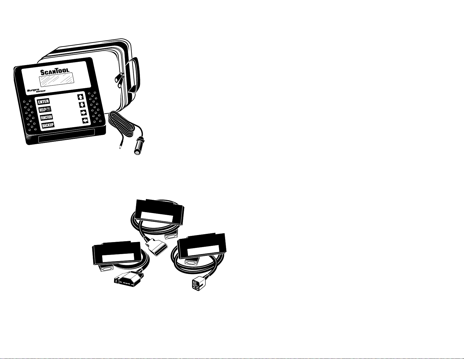
Scan Tool & Application Cartridge
Vehicle Manufacturer Application Cartridges
The manufacturer-specific Application Cartridges offer a universal approach in changing software as vehicle technology changes. Actron’s separate cartridge and cable
system lets you add vehicle applications to meet your needs.
Cartridge Systems:
GM Cartridge 1984-1995
Ford Cartridge 1984-1995
Chrysler Cartridge 1989-1995
OBD II 1996-up
used by the professionals:
• Large 4 line x 20
character LCD display
• High-impact plastic case
• Durable, easy to use
keyboard
• Removable vehicle cable
adapter
• Removable power cable
1984-1995
GM
1-2 The Scan Tool
Actron’s scan tool was developed by experts in the automotive service industry to
help you diagnose today’s vehicles and
assist you in trouble-shooting procedures.
Computer-controlled vehicles have a network of sensors that creates a series of
inputs to the engine computer. The computer interprets these inputs and sends
outputs (commands) back to the network
to control air, fuel, vacuum, spark and
other critical functions. When a problem
occurs, the computer will store a record of
the event, and take corrective action to
adjust the circuit at fault. If the circuit does
not respond, or the problem cannot be
corrected, a trouble code is stored in the
computer’s memory. In some cases, the
Check Engine light may also be activated.
The scan tool will allow you to monitor
these vehicle events for trouble-shooting
and diagnosis, and to read codes from
the computer’s memory to pinpoint problem areas.
The scan tool uses state-of-the-art 16 “bit”
microprocessor technology and has twice
the computing power of some scan tools
costing thousands of dollars! The scan
tool is programmed to interpret the computer signals and provide you with a “real
time” readout of vehicle data. More importantly, the software programs are written
to provide you with detailed, full-screen
readouts of all data. In addition, the Code
Lookup feature allows you to reference
code descriptions without having to page
through an instruction manual.
When the scan tool is connected to the
data connector, a communication link is
established, allowing the scan tool and
the vehicle’s on-board computer to exchange information. The way in which this
information is exchanged is referred to as
a data stream.
As you use the scan tool, you will become
more proficient in trouble-shooting vehicles using the detailed help messages
and code description information. Actron
will also help you become skilled in using
the scan tool for more than just “scanning”
the vehicle data list. We will show you
many other uses that will expand your
diagnostic limits by using the information
contained in the application manuals that
come with your Application Cartridge. Nostart, driveability, and emission problems
will be easier to diagnose than ever before.
Professional-Style Adapter Cables:
GM ALDL — 12 Pin
Ford EEC-IV/MCU — 7 Pin
Chrysler SCI — 6 Pin
1984-1995
FORD
Optional Cable Adapters:
Chrysler CCD / LH – 6 Pin
Ford/Mazda MECS – 6 Pin
GM J1962-OBD-II – 16 Pin
Ford J1962-OBD-II – 16 Pin
Chrysler J1962-OBD-II – 16 Pin
4
1989-1995
CHRYSLER
5
1-3 Actron CP9110 – What You Get
UP
DOWN
RIGHT
LEFT
®
by
®
TM
1984-1995 GM
When you receive your scan tool, take time
to review all package contents.
The Application Cartridge serial tag is
located on the top center of the cartridge. This
CP9110 123456789
Actron Manufacturing warrants the software programs to
Actron Manufacturing warrants the software programs to
be accurate to the level of information released by the
be accurate to the level of information released by the
serial tag will always be visible when the
cartridge is inserted in the main tool.
Please take time to review all important
Main Tool Model and Serial Tag
documents enclosed. Be sure to review
both boxes for contents.
Review Box Contents
Main Tool Box
In addition to the scan tool you should
have received the following items in the
main tool box:
Cartridge Model and Serial Tag
• The Scan Tool
• Carrying Pouch
• Power Cable
• Main Tool Operator's manual
Application Cartridge Box
The Application Cartridge box that you purchased should contain the following items:
• The Application Cartridge
• Vehicle Cable Adapter
Before You Start
Take time to review the proper procedure
for powering-up your scan tool. The following section, Cartridge and Installation,
should be read before proceeding! This
will help you become familiar with all
operating procedures.
• Application Manual for that vehicle
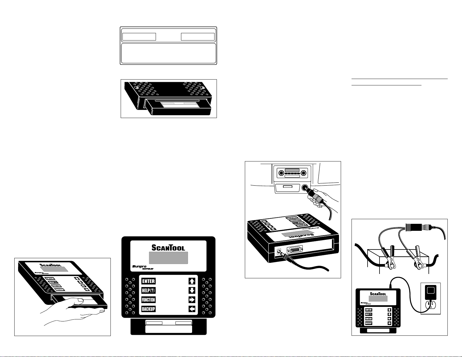
1-4 Cartridge and Installation
Review the Application Cartridge installation procedure before you power-up
your scan tool. Hold the cartridge, serial
number tag up, and slowly insert the car-
SERIAL NO.MODEL NO.
ACTRON MFG.
© COPYRIGHT 1995
SERIAL NO.MODEL NO.
SERIAL NO.MODEL NO.
PATENT PENDING
TM
ACTRON MFG.
ACTRON MFG.
© COPYRIGHT 1995
© COPYRIGHT 1995
PATENT PENDING
PATENT PENDING
Vehicle manufacturer at the time of release.
Vehicle manufacturer at the time of release.
(800) 228-7667
(800) 228-7667
CP9111 123456789
1984-1995 GM
1-2325
1-2325
tridge into the cartridge opening. Align the
cartridge slots with the “keyway” on the
main tool bottom opening. Continue to
gently push the cartridge into the opening
until you feel the main “edge connector”
resistance, then push to engage the cartridge to the cartridge stop. The cartridge
is engaged when the alignment of the
serial number tag is even with the top
edge of the Main Tool opening edge and
flush against the cartridge stop. Refer to
the example.
To remove the Application Cartridge simply
grasp the cartridge end and pull away from
the main tool. This action will disengage
the cartridge from the edge connector. Continue to pull the cartridge out of the opening the rest of the way.
NOTE: You should always have the Application Cartridge installed before you
connect your unit to the power supply.
NEVER UNPLUG THE CARTRIDGE
WHEN POWER IS APPLIED!
1-5 Power Cables and Vehicle Adapters
The scan tool comes with a main power cable
designed to plug into the vehicle cigarette
lighter. The other end of the cable plugs into the
scan tool as shown below.
Connecting to Vehicle
Cigarette Lighter
L
E
F
T
R
I
G
H
T
D
O
W
N
U
P
T
M
b
y
®
®
Your scan tool has been designed to
operate at the same voltage levels as your
vehicle’s computer. It requires a minimum
of 8 volts to power-up. The scan tool is
circuit protected from voltage variations
and power surges. Should you have a
problem with power-up, review Section
3-1: Tool Problems to verify the nature of
your problem. NOTE:
power to the cigarette lighter receptacle when
the ignition key is in the OFF or START positions. Check your vehicle to determine whether
this is the case.
Optional
Battery
Clip
Some vehicles shut off
®
®
by
Application Cartridge Installed
TM
UP
DOWN
RIGHT
LEFT
SERIAL NO.MODEL NO.
ACTRON MFG.
© COPYRIGHT 1995
PATENT PENDING
1984-1995
GM
®
®
by
Connecting to Scan Tool
UP
DOWN
RIGHT
LEFT
Occasionally, you may find it necessary to
connect directly to the vehicle’s battery. In
these cases you may obtain an optional
battery clip adapter from Actron. Actron
also offers an AC power adapter to power
SERIAL NO.MODEL NO.
ACTRON MFG.
© COPYRIGHT 1995
CP9110 12345678
PATENT PENDING
1984-1995
GM
6
the scan tool with standard 110V wall
power. Both of these accessories may be
purchased directly from Actron.
AC 110V to 12V
Power Adapter
7
Vehicle Cable Adapters
UP
DOWN
RIGHT
LEFT
Your scan tool Vehicle Application Cartridge pack
will contain the Application Cartridge, application
manual and vehicle cable
adapter for one manufacturer (GM, Ford, or
Chrysler). The vehicle
cable adapter will be installed on the scan tool by
locating the large connector receptacle on the top
right side of the main tool.
Insert the vehicle cable into
the scan tool receptacle and use the two
“thumb screws” to secure it to the connector as shown in the illustration below. Note
that you will feel a firm seating of the cable
as you secure it to the scan tool connector.
The vehicle cable adapter should always
be connected to the vehicle before power
is applied to the scan tool. This will enable
the scan tool to maintain a proper ground
between itself and the vehicle. If you have
connected to the vehicle, powered-up the
tool, and have difficulty establishing a link
between the scan tool and the vehicle,
check the following:
1. Is the ignition on?
2. Verify you have connected the vehicle
data cable to the vehicle’s Data Link
Connector (DLC).
3. Confirm that proper vehicle information
was entered into scan tool.
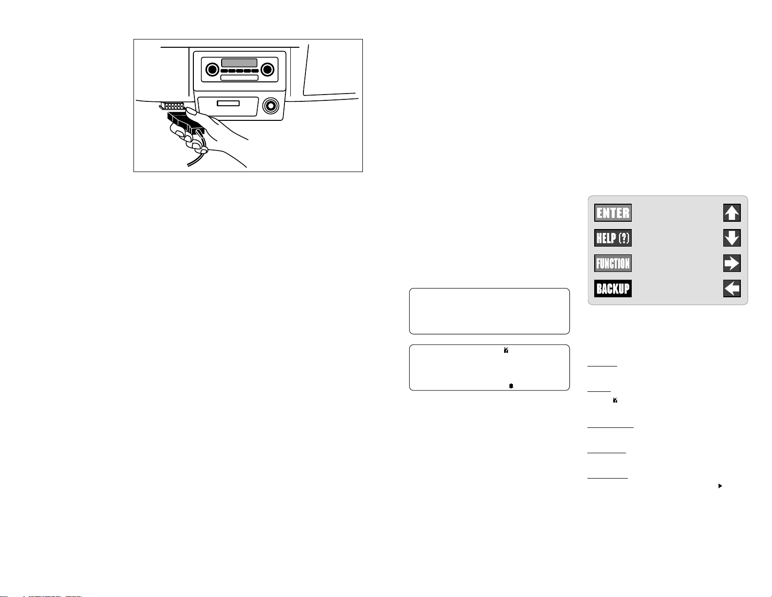
Connecting the
Vehicle Adapter Cable
When attaching the data cable to the vehicle, take time to review the specific application manual for the cartridge you are
using. This will instruct you on correctly
connecting the cable to the vehicle. Many
of the vehicle adapters are “keyed” so that
the adapter will fit only one way. If you find
that you have a special vehicle situation or
the adapter does not fit, call 1-800ACTRON-7 for assistance. Always double
check the application section to be sure
that you are following the proper hook-up
directions. For further help that is not available in the scan tool help screens, see
Section 3: Actron Help for solutions to
your scan tool problems.
As you review the CP9110 Features section on page 1-1 and 1-2, you will note
there is a complete view of accessory
vehicle adapter cables. They are for special applications that only apply to certain
vehicles. If your vehicle is one of these,
you can order cables direct from Actron
by calling (800) 228-7667.
8
1-6 Operating the Scan Tool
Powering-up the scan tool
The scan tool can be powered-up in three
ways. The most widely used way is with
the supplied cigarette lighter adapter. The
scan tool can also be powered up by using
the optional Battery Clip Adapter or 110/12V
AC Power Adapter. If you are poweringup the scan tool for vehicle testing, then
make sure you connect the appropriate
cable to the data connector before you
supply power to the scan tool. If you do not
connect the vehicle data cable now, the
scan tool
connected the data cable. If you just want
to power-up the
then you do not need to attach the cable
to the data connector.
When the
screens is displayed. The screens start
with a “Welcome” screen and end with a
“Key Button Help” screen.
Welcome & Key Button Help Screens
The screens in between the “Welcome”
and the “Key Button Help” screen are for
a tool self-test and the cartridge software
version. Refer to this software version if
you need to contact Actron’s technical
support line with a problem. If you wish to
review the key button definitions, then
push the HELP key; otherwise, press
ENTER to continue forward.
will let you know that you have not
scan tool
scan tool
Welcome To
The ScanTool
By Actron
Press HELP For Key
Button Information.
Press ENTER To Cont
to do self-tests,
powers-up, a series of
Keyboard
The scan tool software was designed for a
“user friendly” approach in navigating through
operational menus. This makes the scan tool
easy to operate. Simply follow the instructions
that match the keyboard symbols and you will
be using your scan tool like an expert in no time.
Since the keyboard is sealed, a damp cloth can
be used to gently clean the surface. (
tion:
DO NOT USE SOLVENTS LIKE
ALCOHOL! This could remove the
keyboard paint!)
Scan Tool Keyboard and Display
Keyboard Functions
The scan tool uses 8 keys to navigate
through the software-user interface:
ENTER Used to enter or answer a
software request.
HELP Used to request help when
symbol is in the upper right hand
the
corner of the display.
FUNCTION Used to return user to
manufacturer’s function list.
BACKUP Used to move one screen
back in scan tool flow.
ARROWS UP or DOWN are always
used to move the solid cursor
direction of the arrow or scroll the data
list in the direction you want to move the
list
LEFT or RIGHT arrows move
the cursor in the direction of the arrow
and allow you to customize a vehicle
data parameter list.
9
Cau-
in the

Display
The scan tool has a 4 line x 20 character
liquid crystal display (LCD) for easy viewing. This makes the scan tool “user friendly”
by offering a large viewing area to display
most Help and Instructional messages.
This also puts more information on the
display instead of referring you to printed
materials. Again the display will support a
number of helpful characters that will
prompt you through test routines. These
characters are shown below:
Question Mark in upper right corner
means there is help available for this
screen.
Bell in lower right corner means the
sound alert is on or active.
Cursor used to select menu choice.
Down Arrow indicates there is additional information on the next screen.
Up Arrow indicates there is additional
information on previous screen(s).
Below is a screen showing how these
symbols will look on your display (NOTE:
This is a GM Function List – Function Lists
for other manufacturers may differ slightly.):
GM Function List
4)Record Data
5)Playback Data
6)Field Service
Lists, Menus, and Questions
The scan tool is designed to be as intuitive
as possible. That is, its functions and controls should be easy to understand and
use the first time you try it. All scan tool
menus and screen lists operate the same
way. By using the UP and DOWN arrow
keys, you can move the cursor to a menu
selection of your choice. The ENTER key
selects that function. Below is an example
of a Function List with several choices
(NOTE: This is a GM Function List –
Function Lists for other manufacturers
may differ slightly.):
GM Function List
1)Read Codes
2)Erase Codes
3)View Data
Note how the cursor is pointing at 1) Read
Codes. If you wish to read trouble codes,
press ENTER to select that function. To
make a different choice, such as viewing
data, use the DOWN arrow key to move
the cursor down next to 3) View Data and
press ENTER. This will select the View
Data function.
Sometimes, a list will be longer than three
or four items, and will not fit on a single
screen. In these cases, the down arrow
symbol (
) is visible in the last column of
the display, indicating that there are more
choices on the next screen:
GM Function List
1)Read Codes
2)Erase Codes
3)View Data
To go to the next choice, use the DOWN
arrow key to move the cursor down the list.
NOTE: Pressing the DOWN arrow key
moves the function list one line at a time.
After several DOWN arrow key presses,
the screen below appears.
GM Function List
4)Record Data
5)Playback Data
6) Field Service
Now notice that there are arrows pointing
up and pointing down in the last column.
This indicates that you can use the UP
arrow key to move the cursor to the previous screen or press the DOWN arrow key
several times to move the cursor to the
third screen, shown below:
GM Function List
7)Beeper On-Off
8)English-Metric
9)Code Lookup
Notice now that there is only an arrow
pointing up in the last column. This indicates that you have reached the end of this
list, and that all other choices are on
previous screens. You can return to those
screens by pressing the UP arrow key.
(NOTE: This is a GM Function List – Function Lists for other manufacturers may
differ slightly.).
These up and down arrow characters on
the screen are used throughout the scan
tool’s software. The UP and Down arrow
keys work exactly the same way, even if
you are just scrolling through text such as
the On-Line Help screen shown below:
3.TEST CONNECTOR:
DAMAGED/LOOSE PINS?
4.TOOL SETUP OK ?
CORRECT VINS,ETC?
Note that there are no choices to make
here, and that there is no cursor to move.
There are, however, up and down arrows
in the last column. These arrows indicate
that there are other screens before and
after this one. Using the UP and DOWN
arrow keys, you can scroll through the
entire message.
Occasionally, you may be asked a question by the scan tool which requires a
response. These will always be YES or
NO questions, and are answered in almost the same way you make choices on
a Function List. Below is an example of a
YES/NO question:
View Instructions
For Creating Custom
Data List?
Yes <No>
In these screens, brackets will automatically be next to the default response. If you
wish to accept the default choice, simply
press ENTER. If you wish to change the
answer, use the LEFT or RIGHT arrow key
to move the brackets next to the other
response and press ENTER.
Other Functions & Keys
As you have reviewed moving through
lists and functions in earlier sections, you
probably noticed several other symbols
on the screen. In the upper right-hand
corner of some screens, there is a large
This question mark indicates that On-Line
Help is available for that particular screen:
Operating Error.
Check Connections!
Try Again?
<Yes> N o
To enter On-Line Help, press the HELP
key. For the screen above, the help message would look like this:
RECHECK FOLLOWING:
1.IGNITION KEY ON?
2.HOOKUP TO VEHICLE
TEST CONNECTOR OK?
All On-Line Help screens have their text
typed in ALL CAPITAL LETTERS. This is
another reminder that you are viewing OnLine Help screens and not screens associated with a function of the Function List.
Some On-Line Help messages are longer
than one screen. If this is the case, the
arrow symbols (
column of the display. A
) will appear in the last
means there is
more On-Line Help information available
on the next screen. A means there is
more On-Line Help information available
on the previous screen. Use the UP and
DOWN arrow keys to page up or down
through a series of On-Line Help screens.
.
10
11

The On-Line Help screen shown above
in the last column. To view the next
has a
On-Line Help screen, press the DOWN
arrow key. That screen is shown below:
3. TEST CONNECTOR:
DAMAGED/LOOSE PINS?
4.TOOL SETUP OK?
CORRECT VINS, ETC?
Notice now that both arrow symbols ( )
are visible in the last column of the display.
This indicates that you can either page up
to a previous On-Line Help screen, or
page down to the next On-Line Help
screen by using the UP and DOWN arrow
keys. The previous On-Line Help screen
is always the one you just viewed, just as
with Function Lists.
Another symbol on the screen you might
have noticed is the bell (
) symbol in the
lower right-hand corner as shown below:
Press HELP For Key
Button Information.
Press ENTER To Cont
This bell symbol indicates that the sound
alert is on or active. Each time you press
a key, you should hear a beep. If you do not
see this symbol, then the keys should
remain silent when pressed. Information
on changing this setting is found in section
1-7: Scan Tool Setup.
1-7: ScanTool Setup
Tool Setup is used to change the scan
tool’s default sound and measurement
unit settings. To change the scan tool’s
default settings, select the Tool Setup
option from the Function List (NOTE: This
is a GM Function List – Function Lists for
other manufacturers may differ slightly.):
GM Function List
7)Beeper On-Off
8)English-Metric
9)Code Lookup
After selecting the Tool Setup option, you
are given the choice to change either the
ScanTool’s measurement units or whether
the beeper will be On or Off. If the bell (
symbol appears in the lower right hand
corner of the display, then the beeper is
turned On.
Setup Tool For
1) English/Metric
2) Beeper On/Off
Depending on whether you select English/
Metric or Beeper On/Off, the ScanTool will
display one of the following screens:
Measurement Units
English (Default)
Metric
Beeper Sound
On (Default)
O f f
When the beeper sound is turned Off, the
bell (
the lower right hand corner of the display.
NOTE: If you change the Beeper and
Measurement Units to a setting other than
the default, then all changes will revert
back to the default settings the next time
the scan tool is used.
) symbol will no longer appear on
Section 2: Vehicle Computer Basics
2-1 Basics of Computer-Controlled Cars
This section explains the engine computer control system, the types of sensors
and how the computer controls engine
fuel delivery, idle speed and timing. Additional information may be found in technical support books at your local library or
auto parts store. The more you know about
the computer system, the better you can
diagnose vehicle computer problems.
Computer controls were originally installed on vehicles to meet federal gov-
)
ernment regulations for lower emissions
levels and improved fuel economy. This
began in the early 1980’s when basic
mechanical systems were no longer able
to accurately control key engine parameters. A computer could be programmed
to control the engine under various operating conditions, making the engine more
reliable. While these early systems were
very limited in the scope of their control,
providing only 10-14 trouble codes, they
did help guide the vehicle repair process.
Today, computer controls have made cars
and trucks faster, cleaner, and more efficient than ever before. In fact, without the
government mandates for fuel efficiency
and emissions control, cars and trucks
today would not be nearly as powerful,
reliable, and comfortable as they are.
What the computer controls:
The main control areas of the vehicle
computer are fuel delivery, idle speed,
spark advance, and emissions controls.
Some on-board computers may also control the transmission, brakes, and suspension systems as well.
What has not changed?
A computer-controlled engine is very similar to the older, non-computerized en-
gine. It is still an internal combustion engine with pistons, spark plugs, valves, and
camshaft(s). The ignition, charging, starting, and exhaust systems are very similar
as well. You test and repair these systems
just as before. The technical manuals for
these components show you how to perform the tests. Additionally, compression
gauges, vacuum pumps, dwell/tach
meters, engine analyzers, and timing
lights will continue to be used.
The Engine Computer Control system
The vehicle’s on-board computer, or
Powertrain Control Module (PCM), is the
“heart” of the system. It is sealed in a metal
box and connected to the rest of the engine by a main wiring harness. The PCM
is located, in most cases, in the passenger
compartment, behind the dashboard or in
the “kick panel” position, although some
manufacturers locate the computer control module in the engine compartment
area. Most PCMs can withstand a lot of
vibration and are built to live in a rugged
environment.
The PCM is permanently programmed by
the factory engineers. The program is a
complex list of look-up tables and instructions telling the computer how to control
the engine based on various driving conditions. To do its job, the computer uses
sensors to know what is happening and
then provide instructions back to a network of switches and actuators throughout the vehicle.
Sensors, switches, and actuators give
the computer information
Sensors are devices which measure operating conditions and translate them into
signals the computer can understand.
12
13

Some examples of sensors: thermistors
(for temperature readings), potentiometers (like a throttle position sensor), relays (for voltage and signal readings), and
signal generators (such as an 02 sensor).
The network of sensors has the job of
delivering information the computer needs
to know by converting it into electrical
signals the computer can understand. Signals running from sensors to the PCM are
referred to as “inputs.”
Sensors monitor key things such as:
• Engine Temperature
• Intake Manifold Vacuum
• Throttle position
• RPM
• Incoming Air Temperature
• Volume of Incoming air
• Air Fuel Ratio, in percentage ( % )
INPUT
SENSORS
BRAINS OF THE
OUTPUT
ACTUAT ORS
COMPUTER
Switches and Actuators are electric devices energized by the computer to allow
commands to perform a specific function.
Switches are often called relays (such as
the coolant fan switch). Actuators might
include solenoids (such as fuel injector
valves) and small motors (such as the Idle
Speed Control). Not all of the computer’s
outgoing signals are routed to switches
and actuators. Sometimes information is
sent to other system computers like transmission, brakes, ignition modules, and trip
computers. Signals running from the PCM
to other components are called “outputs.”
How the computer controls fuel delivery
Engine operation and emissions performance depend upon precise fuel delivery
and ignition control. Early computer systems controlled fuel by electronically adjusting the carburetor metering and jet
systems. Soon, however, this was replaced by the more precise fuel delivery of
fuel injection.
In an electronically carbureted system,
the computer simply controls fuel flow
based on how far the throttle is opened by
the driver. The computer “knows” how
much air can flow through the carburetor
at various throttle openings, and adds the
appropriate amount of fuel to the mixture
at the carburetor.
Fuel injection is somewhat more sophisticated in the way it delivers fuel. The
computer still adds an appropriate amount
of fuel to the entering air, but now it uses
fuel injectors (either in a throttle body or at
each intake port). Fuel injectors are far
more precise than carburetor jets, and
create a much finer fuel “mist” for better
combustion and increased efficiency. In
addition, most fuel injection systems have
ways of measuring exactly how much air
is entering the engine, and can calculate
the proper air/fuel ratio using lookup
tables. Computers no longer have to “estimate” how much air the engine is using.
In many modern systems, the computer
also uses information provided by sensors to give it an idea of how well it is doing
its job, and how to do it better. Sensors can
tell the computer how warm the engine is,
how rich or lean the fuel mixture is, and
whether accessories (like the air conditioner) are running. This feedback information allows the computer to “fine tune”
the air/fuel mixture, keeping the engine
operating at its peak.
What the Computer needs to know:
• Engine operating condition. Sensors
used are: coolant temperature, throttle
position, manifold pressure (vacuum),
air flow and RPM.
• Air intake. Sensors used are: mass air
flow, manifold absolute pressure, manifold air temperature and RPM.
• Air/fuel mixture status. Sensors used
are: oxygen sensor(s).
NOTE: Not all engines use every sensor
listed above.
Open and Closed Loop Modes:
Open or closed loop operation refers to
the way the computer is deciding how
much fuel to add to the air entering the
engine. During cold start and other low
demand, low temperature situations, the
computer operates in open loop mode.
This means that it is relying on a set of
internal calculations and data tables to
decide how much fuel to add to the incoming air. It uses sensors such as the coolant
temperature sensor (CTS), the throttle
position sensor (TPS), and the manifold
absolute pressure sensor (MAP) to determine optimum mixtures. The important
difference here is that it
does not
check to
see if the mixtures are correct, leaving the
computer adjustment loop open.
In closed loop mode, the computer still
decides how much fuel to add by using the
sensors listed above, and by looking up
the appropriate numbers on a data table.
However, it now checks itself to determine
whether the fuel mixture is correct. It is
able to check itself by using the information provided by the oxygen sensor(s)
(O2S) in the exhaust manifold. The oxygen sensors will tell the computer if the
engine is running rich or lean, and the
computer can take steps to correct the
situation. In this way, the computer closes
the adjustment loop by checking itself and
making necessary corrections. It should
be noted that the O2 sensors must be at a
very high operating temperature (approximately 650° F) before they will begin to
feed information back to the computer.
This is why open loop mode is neces-
sary—to give the O2 sensors time to warm
up to operating temperature.
As long as the engine and O2 and Coolant
Temperature Sensors are at operating temperature, the computer can operate in the
closed loop mode. Closed loop mode insures that the air/fuel mixture is at the ideal
14.7:1 air/fuel ratio needed for efficient
combustion. But in stop and go cycles, the
O2 sensor may in fact cool down enough
that the computer will need to rely on a set
of internal parameters and go into open
loop mode again. In some cases, this may
also happen during extended periods of
idling. Many newer vehicles now use
heated O2 (HO2S) sensors to prevent this
condition.
In many vehicles, the computer controls
other systems related to open and closed
loop modes, including idle speed, electronic spark control, exhaust gas recirculation, and transmission torque converter
clutches. In open loop mode, some of these
systems will be adjusted to speed the warming of the engine and get the computer into
closed loop mode as quickly as possible.
OBD II: The Next Horizon
In 1994, many manufacturers began equipping cars with a new class of computer
technology which puts more processing
power under your dash than ever before. It
is called On-Board Diagnostics, Second
Generation, or OBD-II. It is required on all
vehicles sold in the US beginning January
1, 1996 (though most domestic manufacturers introduced it earlier than required),
and offers increased system monitoring
and diagnostic information. This new system will store a library of 400 general
trouble codes and another 400 manufacturer-specific codes. These codes cover
Body Systems (B-Codes), Chassis Systems (C-Codes), and Power Train Systems
14
15

(P-Codes). Now, basic terms are standardized and all generic codes will share a
common format and terminology that the
manufacturers and the Society of Automotive Engineers (SAE) designed. You
will be glad to know that as your car gets
smarter, it will be easier for you to keep
track of what is going on under the hood.
2-2 About Codes
Where do Trouble Codes come from and what are they for?
find
Engine computers can
The computer systems in today’s vehicles
do more than control engine operations—
they can help you find problems, too! Special testing abilities are permanently programmed into the computer by factory
engineers. These tests check the components connected to the computer which
are used for (typically): fuel delivery, idle
speed control, spark timing, emission systems, and transmission shifting. Mechanics have used these tests for years. Now
you can do the same thing by using your
Actron scan tool!
Engine computers perform special tests
The engine computer runs the special
tests, depending on the manufacturer,
engine, model year, etc. There is no “universal” test that is the same for all vehicles.
The tests examine INPUTS (electrical signals going INTO the computer) and OUTPUTS (electrical signals coming OUT of
the computer), as well as internal calculations made by the computer. Input signals
which have “incorrect” values, or output
circuits which do not operate properly are
noted by the test program and the results
are stored in the computer’s memory.
These tests are important. The computer
cannot control the engine properly if it has
incorrect input information or faulty output
circuits.
problems
Code numbers reveal test results
The test results are stored by using code
numbers, usually called “trouble codes”
or “diagnostic codes.” For example, a code
22 might mean “throttle position sensor
signal voltage is too low.” Code meanings
are a part of your scan tool’s software—all
you have to do is look them up! But since
code definitions vary with manufacturer,
model year, and engine, you may also
want to refer to a vehicle service manual
for additional information. These manuals are available from the manufacturer,
other publishers, or your local public library. See page 2 for more information on
ordering service manuals.
Read Trouble Codes with the scan tool
You can obtain trouble codes from the
engine computer memory by using the
scan tool. You can also monitor the operation of systems throughout the vehicle,
helping to pinpoint the system where there
may be a problem. Once you have read
the trouble codes, you can either:
• Have your vehicle professionally serviced.
Or,
• Repair the vehicle yourself using the
trouble codes to locate the source of the
problem.
Trouble Codes and Diagnostics help
you fix the problem
To find the cause of the problem yourself,
you need to perform special test procedures called “diagnostics.” These procedures are in the vehicle service manual,
and your scan tool makes it easy to locate
and diagnose malfunctioning systems.
There are many possible causes for any
problem. For example, suppose you
turned on a wall switch in your home and
the ceiling light did not turn on. Is it a bad
bulb or light socket? Are there problems
with the wiring or wall switch? Maybe
there is no power coming into the house!
As you can see, there are many possible
causes. The diagnostics are written for
servicing a particular trouble code take
into account all the possibilities. If you
follow these procedures, you should be
able to find the problem causing the code
and fix it yourself.
Actron makes it easy to fix computercontrolled vehicles
Using the Actron scan tool to obtain
trouble codes is fast and easy. Trouble
codes give you valuable knowledge whether you go for professional service or
do it yourself. Now that you know what
trouble codes are and where they come
from, you are well on your way to fixing
today’s computer-controlled vehicles!
2-3 When to Read Codes
Many vehicles have a “Malfunction Indicator Lamp” or MIL, which has been referred to
as a “Check Engine” light in the past. With the advent of OBD-II, all engine trouble lights
are now called “Malfunction Indicator Lamps” or MIL.
Use the Malfunction Indicator Lamp to tell you when trouble codes have been
stored in memory:
About the Malfunction Indicator Lamp
• “Check Engine”
• “Service Engine Soon”
• “Service Engine Now”
• marked with a small engine picture or
diagram
The Malfunction Indicator Lamp is normally OFF when the engine is RUNNING.
Malfunction Indicator Lamp:
normal operation
The engine computer turns the Malfunction
Indicator Lamp on and off as needed. This
dashboard message is either amber or
red and labeled:
NOTE:
The Malfunction Indicator Lamp
will turn on when the ignition key is in ON
position, but the engine is OFF prior to
starting the vehicle. This is a normal test of
all the dashboard message lights.
16
17

Malfunction Indicator Lamp:
problem spotted
If the Malfunction Indicator Lamp does not
come on, you may have an electrical problem which needs repair. Refer to the “Diagnostic Circuit Check” steps in the “Basic
Diagnostic Procedures” section of your
vehicle service manual.
Malfunction Indicator Lamp:
intermittent problem
When the light remains ON after the engine is RUNNING:
• The computer sees a problem that does
not go away (known as a “current” failure).
• The light will stay on as long as the
problem is present.
• A trouble code is stored in computer
memory (a “history” or “memory” code).
• Use the scan tool at the earliest convenient time to obtain codes.
When the light comes ON, then goes OFF
while the engine is running:
• The computer saw a problem, but the
problem went away (known as an “intermittent” failure).
• A trouble code is stored in computer
memory (a “history” or “memory” code).
• The light went out because the problem
went away, but the code stays in
memory.
• Use the scan tool at the earliest convenient time to obtain codes.
NOTE:
The computer will automatically
erase these codes after several restarts if
the problem does not return.
Poorly running engine, no Malfunction
Indicator Lamp
Most likely, this condition is not due to
computer system failures, but reading
codes can still be useful as part of a basic
trouble-shooting procedure. Check wiring and bulb for “Check Engine” light
failures. Refer to vehicle service manual
for additional diagnostic information.
IMPORTANT:
equipped with Malfunction Indicator
Lamps. Some mid-80’s Fords, for example,
did not use a Malfunction Indicator Lamp
to warn of problems. On vehicles without
Malfunction Indicator Lamps, it is more
difficult to recognize problems. Some
symptoms of a computer- or sensorrelated problem might be:
• Hard starting
• Poor idle quality
• Poor fuel mileage
• Misfiring or hesitation
• Black or dark gray smoke from tailpipe
• Failure of emissions tests
In vehicles without a Malfunction Indicator
Lamp, it is important to be alert to any
warning signs of computer system trouble.
This is why the scan tool is so valuable.
With it, you can diagnose any vehicle’s
electronic systems, regardless of whether
the vehicle is equipped with a Malfunction
Indicator Lamp. It is also important to note
that vehicles without Malfunction Indicator Lamps DO store trouble codes just like
any other computer-controlled vehicle.
Reading codes is still a very important part
of diagnosing problems on these vehicles.
NOTE:
the Malfunction Indicator Lamp also signals an emissions-control related failure.
The vehicle may not run any differently,
but the OBD-II system is designed to note
very small changes in the engine’s operation which could lead to emissions damage or failure.
Some vehicles may not be
On vehicles equipped with OBD-II,
Section 3: Actron Help
3-1 Tool Problems
There may be times when your scan tool
does not seem to be communicating with
the vehicle. It is possible that the vehicle’s
computer will stop communicating, but for
the most part, if you loose the “link,” you
should check the vehicle power adapter
and the cigarette lighter circuit first. Since
the scan tool has built-in diagnostics, it is
easy to isolate a problem with the ScanTool
itself. There will be two basic types of
problems that you will deal with: vehicle
problems and tool problems. Both might
affect your test. Remember, the scan tool
always goes through a SELF CHECK
each time you power the unit up, before
testing. Use the trouble-shooting tips below to help diagnose scan tool problems
before calling Actron’s Technical Support
line:
1. The scan tool will not power-up:
A.Check the cartridge – Is it properly
seated?
B. Check the cigarette lighter for power.
Take the cigarette lighter element and
plug it in to verify that it is heating up. If
not, check lighter fuse.
UN-plug and plug back in to verify the
C.
cigarette lighter end is properly seating in
the vehicle cigarette lighter receptacle.
2. Tool will not “Link” to the vehicle computer:
A.Unplug the vehicle Data Link Connec-
tor (DLC) adapter and plug it back in to
verify that it is properly plugged into the
vehicle DLC.
B.Review the vehicle VIN information and
verify that you have properly entered
the correct vehicle VIN information in
the scan tool setup. Also review the
Actron supported vehicle list (found in
scan tool Application Cartridge
manual).
C. In some GM cars, if there is a Trouble
Code set that refers to the internal
MEMCAL-PROM, you may not get a
vehicle data stream.
3. Your scan tool will not record data:
A.Take time to review the vehicle applica-
tion manual for the vehicle that you are
working on. Refer to the data recording
section, following the instructions and
try again.
B.Verify that the scan tool memory buffer
is not already full.
C. Use the scan tool self-test and verify
that the on-board RAM memory is okay.
4. Your Keyboard does not function properly:
A.Perform the Keyboard Test by entering
the Self-Test and select the Keyboard
Test function. This will test out all buttons along with the sound alert.
B.If the keyboard test shows nothing
and you still experience the problem,
then call Actron’s technical support personnel at 1-800-ACTRON-7.
18
19

3-2 Car Problems
If your scan tool is having difficulty “linking” with the vehicle computer, be sure
that you have double checked all scan
tool interfaces, including the power connectors and the DLC connection. When
you are sure that the scan tool is not
malfunctioning (run scan tool Self-Tests),
then the problem may be with the vehicle’s
electrical system or with the vehicle computer itself. Check the following:
• If you are using the cigarette lighter
power adapter, verify that the vehicle’s
cigarette lighter and fuse are OK.
• If the cigarette lighter adapter is used to
power-up the scan tool, then make sure
the vehicle’s battery has a minimum 8
volt charge. The scan tool requires a
minimum of 8 volts to power-up.
• Verify the ignition key is ON and not in
the accessories (ACC.) position.
• Check the vehicle’s on-board computer
for a blown PCM fuse. The PCM fuse is
located on the fuse block in the passenger compartment. If the PCM fuse is
blown, the vehicle’s on-board computer
cannot transmit data.
• Check to be sure your vehicle’s calibra-
3-3 Scan Tool Self-Tests
Scan tool Self-Tests are used to test the
operation of the scan tool’s display, keyboard, and internal memory. The Tool
Self-Tests menu can be accessed when
the scan tool is initially powered-up, and
from the Function List. Convenience is the
reason the Tool Self-Tests menu is accessible in two ways. If the scan tool has a
display problem on power-up, you do not
want to enter vehicle set-up information
just to get to the Function List to run the
Display Self-Test. It is far more convenient
to have the Tool Self-Tests menu acces-
tion PROM matches the vehicle setup.
Some GM vehicles have had replacement PROMs installed from newer vehicles to correct driveability problems.
Check the scan tool Application Cartridge manual for applicable models
and years.
• Make sure the vehicle’s on-board computer has a good ground. If your
vehicle’s on-board computer has a
ground going directly to the computer’s
case, then clean up this connection
and apply a conductive grease to the
mating surfaces.
• On some carbureted engines, the ignition key must be ON and the engine
OFF in order to establish communication between the scan tool and the
vehicle’s on-board computer. If the engine was running when the Operating
Error occurred, then turn the ignition
key OFF and then ON, but
the engine
.
do not start
• As a last resort, the vehicle’s on-board
computer or calibration PROM may be
defective. Check vehicle service manual
to determine correct computer tests for
your particular vehicle.
sible during scan tool power-up. If a keyboard problem happens while you are
Viewing Data, it is easier to run a Keyboard Self-Test from the Function List
than to remove and then re-apply power
to the scan tool.
After the ENTER key is pressed, the display on power-up looks like this:
Select Function
1)New Vehicle
2)Tool Self-Test
20
The screen below is how the Tool SelfTests option appears on the Function List
(NOTE: This is a GM Function List. Function Lists for other manufacturers may
differ slightly):
GM Function List
7)Tool Setup
8)Tool Self-Test
9)Code Lookup
To select Tool Self-Tests on either screen,
use the UP and DOWN arrow keys to
move the cursor so it is pointing to the Tool
Self-Tests option, then push the ENTER
key to select this option.
After selecting the Tool Self-Tests option,
you will be given a menu of scan tool selftests to choose from:
Tool Self-Test
1)Display Test
2)Keyboard Test
3)Memory Test
From the above menu, use the UP and
DOWN arrow keys to move the cursor so
it is pointing to the Self-Test option of your
choice, then push the ENTER key to select
this option.
Display Test
After you have selected Display Test as
your choice, a screen detailing the test is
displayed. The Display Test will fill every
pixel of the ScanTool’s LCD display with
a solid black character. Press ENTER to
display solid black characters.
ENTER To Test. Look
For Missing Spots
In Display. Press
BACKUP When Done
The Display Test Screen is shown below.
Look for pixels that are not black. In other
words, look for missing spots in the solid
black characters. Press the BACKUP key
to return to the Tool Self Test Menu when
done. If you selected Tool Self-Test from
the Function List, then press the FUNCTION key to return to the function list at any
time.
NOTE:
The beeper is disabled while the
Display Test Screen is visible. Therefore
any key press will not register a beep.
Keyboard Test
The Keyboard Test is used to check the
functionality of the scan tool’s keyboard.
After you select Keyboard Test from the
Tool Self-Test Menu, the Keyboard Test
screen with instructions is displayed.
Push Button To Test
Key And Display
Name Key:
BACKUP When Done.
Each time you press a key, check scan tool
display. The key name should appear and
the scan tool should beep. For example,
if you press the UP arrow, the screen will
display “Key: UP ARROW.” If the button
name is not displayed, the key is not
working. The only exception is the BACKUP
key. When the BACKUP key is pressed,
the scan tool returns to the Tool Self-Test
Menu. If you are not returned to the Tool
Self-Test Menu, then the BACKUP key is
NOTE:
not working.
The FUNCTION ke y
will not return you to the Function List
while you are keyboard testing.
Memory Test
The scan tool has already run a Memory
Self-Test during power-up. It is assumed
that the scan tool passed the Memory SelfTest on power-up, because you should
not have proceeded any farther if it failed.
Once you have reached the Function List,
the scan tool may have trouble playing
21

back recorded data, displaying trouble
code definitions, or doing any other function that uses the scan tool’s internal
memory. If this happens, it is a good idea
played. Press the ENTER key to return to
the Tool Self-Test Menu.
Memory Test Failed
to run the Memory Test again. From the
Tool Self-Test Menu, select the Memory
Test option. A “working please wait” mes-
Press ENTER To Cont
sage is displayed while the scan tool tests
its internal memory:
Memory Test Passed
Working
** Please Wait **
Press ENTER To Cont
NOTE:
When the Memory Test is completed,
either a “Memory Test Failed!” or a
“Memory Test Passed!” message is dis-
If you selected Tool Self-Test from
the Function List, then press the FUNCTION
key to return to the function list at any time.
Section 4: Accessories and How to Order
4-2 Call Actron
In addition to your local dealer, all Actron
equipment and replacement parts are
available directly from the Actron factory.
Product catalogs, pricing information, and
replacement components can be ordered
by contacting Actron directly.
By US mail:
Actron Manufacturing Company
15825 Industrial Parkway
Cleveland, OH 44135, USA
By phone:
1-800-228-7667
By fax:
(216) 651-2388
For Technical Support call:
1-800-ACTRON-7
4-3 E- Mail &
Internet Address
Actron is also available electronically for
comments and ordering information.
Actron’s E-Mail address is:
sunpro@actron.com
And while you’re on-line, be sure to check
out Actron’s Website, where you’ll find
equipment information, new products, and
technical tips to help you make the most of
your new Actron ScanTool.
On the World Wide Web:
http://www.actron.com
4-1 Where to Buy
Actron offers a complete line of high quality automotive diagnostic and repair
equipment. Additional cartridges, cables,
connectors, and adapters for the scan
Actron
Kits: Model Number
GM OBD II cable kit CP9115
Ford Probe MECS cable kit CP9116
Chrysler L-H engine cable kit CP9120
Chrysler OBD II cable kit CP9117
Battery Clip Adapters CP9118
AC power converter 110/12V CP9119
tool are available from the local retail
store where you originally purchased
your scan tool. The table below lists the
scan tool accessories.
Actron
Replacement Parts: Part Number
Cigarette power cable 38-1908
Carrying Case 400-2080
Main Tool operators manual 2-218601
GM cartridge manual 2-218301
Ford cartridge manual 2-218401
Chrysler cartridge manual 2-218501
22
23

Section 5: Glossary of Terms
Actuator: Devices that are powered by the PCM
to control things. Actuator types include relays,
solenoids, and motors. Actuators allow the PCM
to control engine operation.
A/F: Air/Fuel ratio. This refers to the proportion of
air and fuel delivered to the cylinder for combustion. For example, if you have 14 times more air
than fuel (by weight) then the A/F ratio is 14:1
(read as “fourteen to one”). The ideal operating
A/F ratio in an automotive application is 14.7:1.
Check Engine Light (CEL): The “Check Engine”
light (CEL) will illuminate when the PCM detects
a circuit malfunction in any of the engine feedback circuits. When the malfunction occurs, the
CEL will remain lit as long as the PCM detects the
circuit problem. This will automatically set and
store a trouble code in the PCM’s memory. Some
manufacturers also refer to the CEL as a Malfunction Indicator Light (MIL), or the Emissions Maintenance Lamp (EMR) on some Chrysler trucks.
C3 or CCC: Computer Command Control. The
name of the General Motors electronic engine
control system used on most vehicles built since
1982.,
Chrysler Serial Communication Interface (SCI):
This is Chrysler’s vehicle adapter (or Data Link
Connector) used to link scan tools with the PCM.
Early Chrysler OBD systems (1981-83) broadcast
trouble codes, but gave no operating parameter
data. In 1983, the second phase of Chrysler
OBD, called the Serial Communication Interface
(SCI), was introduced with expanded serial data
and many test modes for the technician to access
with a scan tool. SCI provides the following
modes to access vehicle data: Diagnostic Test
Mode, Circuit Actuation Test Mode (ATM), Switch
Test Mode, Sensor Test Mode, and Engine
Running Test Mode. Each of these modes allow
for different procedures of diagnostic tests and
test routines. These routines are programmed
into the Chrysler Logic Module (LM) which then
passes the information on to the power module
or Single Board Engine Controller (SBEC). The
vehicle diagnostic adapter is located in the engine compartment on the right-hand side, next to
the SBEC unit with a dust cap marked “Diagnostic.”
Closed Loop (C/L): This is when a control system
performs an action (expecting a certain result),
then checks the results and corrects its actions
(if necessary) until the desired results are achieved.
Example: Fuel delivery. The PCM operates a fuel
injector in a way that should deliver an optimum
air/fuel mixture, as long as everything in the fuel
system is operating as expected. In closed loop
operation, the PCM uses the oxygen sensor to
check the results (fuel delivery may be different
than expected because of variations in fuel
pressure or injector operation). If the oxygen
sensor indicates a “rich” condition, the PCM will
compensate by reducing fuel delivery until the
oxygen sensor signals an optimum air/fuel mixture. Likewise, the PCM will compensate for a
“lean” condition by adding fuel until the oxygen
sensor once again signals an optimum air/fuel
mixture.
Thus, closed loop operation means the PCM can
“fine tune” control of a system to achieve an exact
result providing the PCM has a means to check
results (like an oxygen sensor).
Data Link Connector (DLC): The Data Link
Connector (DLC) is a universal term for the
interface port between the vehicle’s on-board
computer and the ScanTool. It is sometimes
referred to as the Assembly Line Diagnostic Link
(ALDL), Vehicle Interface Port (VIP), or Serial
Communication Interface (SCI). The DLC is able
to transmit PCM data to the ScanTool as it is
processed. The DLC may be located in the
engine compartment or in the passenger compartment, depending on manufacturer. DLC design also varies from manufacturer to manufacturer, ranging from a 6-pin to a 17-pin connector
interface. All vehicles with OBD-II use a 16-pin
connector located in the passenger compartment. The ScanTool requires manufacturer-specific adapter cables to link with non-OBD-II DLCs.
Data Stream: This is the actual data communications broadcast from the vehicle’s PCM to the
diagnostic connector. The individual manufacturers determine the number of “data bytes” a
specific engine will broadcast. The size of the
data stream is usually dependent on the complexity of the engine, transmission, ABS, and
other systems supported by the PCM. All manufacturers supply program documents for each
year, engine, and option combination that a
particular PCM supports in all the manufacturer’s
vehicles. This information is used to design and
build aftermarket diagnostic equipment.
Detonation: Uncontrolled ignition of the air/fuel
mixture in the cylinder. Also referred to as “knock,”
detonation indicates extreme cylinder pressures
or “hotspots” which are causing the air/fuel mixture to detonate early. High cylinder pressures
may be caused by excessive load (trailer towing,
A/C operation, etc.) or by too much spark advance. High octane fuel has a higher resistance
to uncontrolled ignition, and may be used to
control detonation when the PCM is unable to
retard timing sufficiently to prevent it from occurring. NOTE: High octane fuel is not a cure for the
problem, only the symptom. If your vehicle experiences long-term detonation, check for other
causes.
Diagnostic Trouble Codes: Diagnostic Trouble
Codes (DTC) indicate a malfunction flagged by
the PCM. The PCM will display a corresponding
numerical code number based on a look-up table
in the program of the on-board computer. Depending on the manufacturer, the number of
DTCs vary by vehicle and supported systems.
Most systems have the ability to store codes in
memory, which are commonly referred to as
“history codes” or “soft codes.” Malfunctioning
circuits will generate continuous Check Engine
lamp illumination, called “current codes” or “hard
codes.” History codes, based on the
manufacturer’s diagnostic strategy, will be cleared
from the PCM’s memory after several ignition
circuit start cycles if the circuit does not reflect the
failure again. This capability does allow the
technician to access some information on which
circuits were malfunctioning at a previous point.
OBD-II systems will transmit many more DTCs
than the past systems, and therefore will allow a
technician the ability to better pin-point failures
and past events. They only way to clear codes on
OBD-II systems will be with a scan tool that has
the proper programming to perform the function.
DIS: Distributorless Ignition System or Direct
Ignition System. A system that produces the
ignition spark without the use of a distributor.
Duty Cycle: A term applied to frequency signals
— those which are constantly switching between
a small voltage value (close to zero) and a larger
value (usually 5 volts or more). Duty cycle is the
percentage of time the signal has a large voltage
value. For example, if the signal is “high” (large
voltage) half of the time, the duty cycle is 50%.
If the signal is “high” only one fourth of the time,
then the duty cycle is 25%. A duty cycle of 0%
means the signal is always at a “low” value and
not changing. A duty cycle of 100% means the
signal is always at a “high” value and not changing. The PCM uses duty cycle type signals when
it wants more than just “on-off” control of an
actuator. This is how it works: A 50% duty cycle
signal going to a vacuum switching solenoid
means the solenoid will be “on” (passing full
vacuum) half the time, and “off” (passing no
vacuum) half the time. The average amount of
vacuum passing through the solenoid will be one
half the full value because the solenoid is only
“on” for half the time. This signal changes at a
rapid rate, as often as ten times per second. Thus
the PCM can get a vacuum controlled actuator to
move halfway between “no vacuum” and “full
vacuum.” Other positions can be achieved by
changing the duty cycle of the control signal
which in turn changes the average amount of
control vacuum.
DVM: Digital Volt Meter. An instrument using a
numeric readout to display measured voltage
values as opposed to a moving needle on a
gauge face. Usually the instrument has other
measuring capabilities, such as resistance and
current, and may be called a Digital Multi-Meter
(DMM). Most DVMs have 10 Megaohm input
impedance. This means the circuit under test will
not be electronically disturbed when the DVM is
connected for a measurement.
ECM: Electronic Control Module. The “brains” of
the engine control system. It is a computer
housed in a metal box with a number of sensors
and actuators connected with a wiring harness.
Its job is to control fuel delivery, idle speed, spark
advance timing, and emission systems. The PCM
receives information from sensors, then energizes various actuators to control the engine. The
ECM is frequently called the PCM (Powertrain
Control Module) in vehicles having other computers.
These other computers are used for climate
control, entertainment systems, transmissions,
etc.
EFI: Electronic Fuel Injection. A term applied to
any system where a computer controls fuel delivery to the engine by using fuel injectors.
Engine Parameters: This is the translated information that is displayed on the scan tool screen.
Parameters will include the information inputs
and the output signals from the PCM.
24
25

ESC: Electronic Spark Control. This is an ignition
system function that works on vehicles having a
knock sensor mounted on the engine block. The
knock sensor is wired to circuitry in a separate
module (early version) or inside the PCM (later
versions). If the sensor detects engine knock, the
ESC function alerts the PCM which will immediately retard the spark to eliminate the knocking
condition.
EST: Electronic Spark Timing. An ignition system
where the PCM controls the spark advance
timing. A signal called EST goes from the PCM to
the ignition module which fires the spark coil. The
PCM determines optimum spark timing from sensor information – engine speed, throttle position,
coolant temperature, engine load, vehicle speed,
Park/Neutral switch position, and knock sensor
condition.
FBC: Feedback Carburetor. This is used on early
versions of computer-controlled engines. It is a
carburetor which can have its fuel delivery modified by an electronic signal from the PCM. The
signal controls a mixture control solenoid (MCS)
attached to the carburetor body.
Ford Electronic Engine Control IV (EEC-IV):
This is the name of Ford’s Powertrain Control
Module (PCM) used in all Ford cars and trucks
since the mid-1980’s. It is designed to be read by
aftermarket scan tools. Earlier versions of this
PCM were referred to as EEC-I, EEC-II, or EECIII, and were only accessible by the dealer via a
specific diagnostic tool. On carbureted vehicles,
Ford used a system called the Microprocessor
Controlled Unit (MCU), which is accessible through
an adapter similar to the EEC-IV’s. Other variations of the EEC-IV vehicle adapter are used on
Ford’s hybrid vehicles, such as the Probe and some
Escort/Tracer models, which use Mazda PCMs
and have different protocols and codes. Information on these vehicles is widely available, and
most scan tools support these vehicles as well as
the standard Ford EEC-IV systems. Ford’s diagnostic strategy offers several avenues to access
codes and test procedures.
Fuel Injector: An electronically controlled flow
valve. Fuel injectors are connected to a pressurized
fuel supply (fuel pressure is created by a fuel pump).
No flow occurs when the injector is off (not energized).
When the injector is energized, it opens fully, allowing
fuel to flow. The PCM controls fuel delivery by varying
the amount of time the injector solenoids are turned on.
Functional Tests: These are tests of PCMcontrolled systems, such as the fuel pump, the
“Check Engine” light, and other switches and
actuators. Functional Tests are generally dependent on the vehicle manufacturer’s OBD strategy
and the PCM diagnostic architecture. Functional
tests require that the scan tool have the ability to
perform bi-directional communications with the
vehicle’s PCM. This means that the scan tool
must “talk” to the vehicle’s PCM, instead of just
“listening” to the incoming vehicle data stream.
Examples of functional tests are: Chrysler’s actuator/switch tests that allow you to review the
operation of a switch as you turn it on or off from
the driver’s seat, and turning the fuel pump on
and off. On a GM vehicle, a functional test is
placing the vehicle in Ground Mode to check the
PCM’s self-test diagnostics and the “Check Engine” lamp operation.
Ground: The return path for current to flow back
to its source (Usually the negative battery terminal). It is also the reference point from which
voltage measurements are made (the connection place for the negative (-) test lead from a
voltmeter).
Inputs: Electrical signals running into the PCM.
These signals come from sensors, switches or
other electronic modules. They give the PCM
information about vehicle operation.
KOEO: Key On, Engine Off. A test mode where
the PCM is active and feeding data parameters,
but the engine is not running. Because the
engine is not running, some data parameters
may not be accurate or available in this mode. On
Ford vehicles, KOEO testing is the only way to
read memory codes stored in the PCM.
KOER: Key On, Engine Running. A test mode
where the PCM is active and feeding data parameters, and the engine is running. Since the
engine is running, most data parameters should
be available and accurate.
Knock: See “Detonation.”
Knock Sensor: This sensor is used to detect
engine detonation (or “knock”). When spark
knock occurs, the sensor emits a pulsing signal.
Depending on the vehicle, this signal either goes
to the PCM or a separate ESC (Electronic Spark
Control) module. Then the spark advance is
retarded until detonation stops. The sensor
contains a piezoelectric element and is threaded
into the engine block. Vibrating the element
generates the signal pulse. Special construction
makes the element sensitive only to engine
vibrations associated with detonation (“knocking”).
MFI: Multi-Port Fuel Injection. See “MPFI” definition.
MIL: Malfunction Indicator Lamp. Also known as
a Check Engine Light or CEL.
Mode: A type of operating condition, such as “idle
mode” or “cruise mode.”
MPFI: Multi-Port Fuel Injection. A fuel injection
system using one (or more) injector(s) for each
cylinder. The injectors are mounted in the intake
manifold, and fired in groups rather than individually.
M/T: Manual transmission or manual transaxle.
NOx: Oxides of Nitrogen. A pollutant. The EGR
system injects exhaust gases into the intake
manifold to reduce these gases at the tailpipe.
On-Board Diagnostics (OBD): As vehicle manufacturers developed on-board diagnostics for
their service procedures and to meet EPA regulations, the first phase of this computerization
was referred to as OBD. This technology started
in the late 1970’s and carried through to the early
1980’s. Most of these early systems were very
crude, especially when compared to today’s
OBD. Many required a manufacturer-specific tool
to read trouble codes and other computer information. This technology used a feedback loop
system to monitor exhaust emissions and provided computer control of the vehicle’s fuel
system.
On-Board Diagnostics, Phase I (OBD-I): By
1985, the California Air Resources Board (CARB)
had called for more uniform diagnostic systems
to be used on vehicles sold in California. Combined with federal exhaust emission regulations
enacted in the early 1990’s, CARB required that
all vehicles sold in California have an integrated
PCM structure that monitored all critical emissions components. Manufacturers found that it
was simpler to incorporate this system into all their
vehicles built in the USA. In fact, by the end of
1986, most diagnostic procedures were uniform
within each manufacturer, providing an opportunity for generic scan tools to come to market for
the home mechanic.
On-Board Diagnostics, Phase II (OBD-II): With
the passing of the 1990 Clean Air Act Amendment, the EPA imposed more stringent requirements which include the addition of multiple
oxygen sensors, one before the catalytic converter and one after to provide the PCM with
information on catalyst efficiency and condition.
There are also computer-controlled EGR, fuel
pressure regulators, and smart ignition systems.
In addition, OBD-II requires a common diagnostic
connector and location, as well as an industrystandard data message, both defined by an
industry committee made up of engineers from
most major manufacturers and the SAE. Vehicle
manufacturers are required by law to provide at
least a minimum amount of data for emissions
programs to access the critical emissions data
available through OBD-II. OBD-II began to appear in vehicles in late 1994, and is required
equipment on all cars sold in the US after January
1, 1996.
Open (Circuit): A break in the continuity of a
circuit such that no current may flow through it.
Open Loop (O/L): This is when the control system
performs an action (expecting a certain result),
but has no way of verifying if the desired results
were achieved. Example: The PCM operates a
fuel injector expecting a certain amount of fuel to
be delivered (The PCM assumes everything in the
fuel system is performing properly). In open loop
operation, the PCM has no way of checking the
actual amount of fuel delivered. Thus, a faulty
fuel injector or incorrect fuel pressure can change
the amount of fuel delivered and the PCM would
not know it.
In general, a control system operates in open
loop mode only when there is no practical way to
monitor the results of an action. Example: Fuel
delivery during cold engine warm-up. The computer runs in open loop mode because the
oxygen sensor is not hot enough to send a signal.
Without the sensor signal, the computer cannot
check the actual amount of fuel delivered.
O2S: Oxygen Sensor. The oxygen sensor is
threaded into the exhaust manifold, directly in the
stream of exhaust gases. The PCM uses the
sensor to “fine tune” fuel delivery. The sensor
generates a voltage of 0.6 to 1.1 volts when the
exhaust gas is rich (low oxygen content). The
voltage changes to 0.4 volts or less when the
exhaust gas is lean (high oxygen content). The
sensor only operates after it reaches a temperature of approximately 349°C (660°F).
26
27

Outputs: Electrical signals sent from the PCM.
These signals may activate relays or other actuators for control purposes throughout the vehicle.
The signals can also send information from the
PCM to other electronic modules, such as the
ignition or trip computer.
PCM: Powertrain Control Module. The “brains” of
the engine control system. It is a computer
housed in a metal box with a number of sensors
and actuators connected with a wiring harness.
Its job is to control fuel delivery, idle speed, spark
advance timing, and emission systems. The PCM
receives information from sensors, then energizes various actuators to control the engine. The
PCM is frequently called the ECM (Engine Control
Module) in vehicles having other computers.
These other computers are used for climate
control, entertainment systems, transmissions,
etc.
PROM: Programmable Read-Only Memory. A
small, replaceable electrical component hidden
behind an access door on the PCM. The PROM
contains permanent programming information
the PCM needs to operate a specific vehicle
model. Included are vehicle weight, engine and
transmission type, axle ratio, and other specifics.
Relay: A mechanical device for switching high
current circuits on and off. It is electronically
controlled by a low current circuit. Relays allow a
low power PCM signal to control a high power
device such as an electric cooling fan.
ROM: Read-Only Memory. Permanent programming information stored inside the PCM, containing the information the PCM needs to operate a
specific vehicle model.
Sensor: Device which gives the PCM information. The PCM can only work with electrical
signals. The job of the sensor is to take something the PCM needs to know, such as engine
temperature, and convert it to an electrical signal
that the PCM can understand. The PCM uses
sensors to measure such things as throttle position, coolant temperature, engine speed, incoming air mass and temperature, etc.
SFI or SEFI: Sequential Fuel Injection or Sequential Electronic Fuel Injection. A fuel injection
system that uses one or more injectors for each
cylinder. The injectors are mounted in the intake
manifold, and are fired individually in the same
sequence as the spark plug firing order.
Solenoid: A device to convert an electrical signal
to mechanical movement. It consists of a coil with
a wire with a moveable metal rod in the center.
When the power is applied to the coil, the
resulting electromagnetism moves the rod and
performs some mechanical action. The PCM
often uses solenoids to switch vacuum lines on
and off. This allows the PCM to control vacuum
operated devices such as the EGR valve. Fuel
injectors are operated by another type of solenoid.
TBI: Throttle Body Injection. A fuel injection
system having one or more injectors mounted in
a centrally-located throttle body, as opposed to
positioning the injectors close to an intake valve
port. Also called Central Fuel Injection (CFI) in
some vehicles.
Thermistor: A resistor whose resistance changes
with temperature. Thermistors are used as sensors for vehicle coolant and manifold air temperature. The resistance decreases as temperature
goes up, sending a voltage signal to the PCM
where it is converted to a temperature measurement.
Throttle Body: A device which performs the same
function as a carburetor in a fuel injection system.
On a throttle body injection (TBI) system, the
throttle body is both the air door and the location
of the fuel injectors. On port fuel injection systems
(PFI, MPFI, SFI, etc.) the throttle body is simply
an air door. Fuel is not added until the injectors
at each intake port are activated. In each case,
the throttle body is attached to the accelerator
pedal.
Vehicle Adapter: Like General Motors and the
ALDL connector, Ford and Chrysler use Vehicle
Adapter as the name of their diagnostic link. Ford
uses a 7-pin adapter called the EEC-IV self test
adapter. This is generally located in the engine
compartment of Ford vehicles, though specific
location varies (generally it is close to the PCM).
Chrysler has a similar adapter for access to the
Serial Communications Interface (SCI) diagnostic program on those vehicles that support SCI.
This adapter is located on the right-hand side of
the engine compartment, and is a 6-pin configuration. This adapter is usually near the Logic
Controller on the SCI computer.
VIN: Vehicle Identification Number. This is the
factory-assigned vehicle serial number. This number is stamped on a number of locations throughout the vehicle, but the most prominent location
is on top of the dashboard on the driver’s side,
visible from outside the car. The VIN includes
information about the car, including where it was
built, body and engine codes, options, colors,
and a sequential build number. The VIN can also
tell you what adapters you may need to use the
ScanTool with your particular vehicle.
WOT: Wide-Open Throttle. The vehicle operating
condition brought about when the throttle is
completely (or nearly so) open. The PCM will
typically deliver extra fuel to the engine and deenergize the A/C compressor at this time for
acceleration purposes. The PCM uses a switch
or the Throttle Position Sensor to identify the
WOT condition.
28
29
 Loading...