

Page 1
precision electronic solutions
CODE SCANNER
FAVOR DE LEER INSTRUCTCTIVO ANTES DE USAR EL ARTICULO
Car Computer
Code Reader
Domestic GM & Saturn
Lector de Códigos
de Computadoras
de Automóvil
GM y Saturn
nacionales de EE.UU. con
Systemas MCU y EEC-IV (para EUA)
Instrucciónes
en español - página 99
Lecteur de code
d'ordinateur
automobile
GM y Saturn
domestiques Étas-Unis
avec Systèmes MCU ou EEC-IV
Instructions en
français - page 199
¨
Tensi
ón: 14V
Hecho en: China
Para Nombre, Domicilio y Telefono
del Importador: Ver Empaque
1
CP9001
Page 2

2
Page 3
CP9001
™
Congratulations on purchasing your
Actron Code Scanner for accessing
engine trouble codes required for
repairing vehicles equipped with
computers. Your Actron Code
Scanner is made by Actron, the
largest and most trusted name in
automotive diagnostic equipment for
the home mechanic. Y ou can have
confidence this product maintains the
highest quality in manufacturing, and
will provide you years of reliable
service.
This instruction manual is divided into
several key sections. Y ou will find
detailed steps on using the Code
Scanner and important information
about trouble code meanings, how a
computer controls engine operation,
and more!
Identifying the problem is the first
step in solving that problem. Y our
Actron Code Scanner can help you
determine by accessing the engine
computer trouble codes. Armed with
that knowledge, you can either refer
to an appropriate service manual or
discuss your problem with a knowledgeable service technician. In either
event you can save yourself a lot of
valuable time and money in auto
repair. And feel confident that your
vehicle’s problem has been fixed!
Actron offers a compete
line of high quality
automotive diagnostic
and repair equipment.
See your local Actron
dealer for other
Actron products.
CONTENTS
Engine/Transmission Section
1 About Codes................................. 3
2 When to Read Codes ................... 5
3 Reading Codes.............................6
4 Using Codes in a Basic
Troubleshooting Procedure ........10
5 Code Meanings ..........................14
6 Additional Code Scanner
Diagnostic Features ................... 22
7 Computer Basics ........................ 25
8 Glossary .....................................31
Anti-Lock Brake (ABS) Section
9 ABS Basics................................. 38
10 ABS Safety ................................. 44
11 ABS Tips.....................................45
12 Reading ABS Codes .................. 47
System 1: Bosch 2S ......................... 51
System 2: Bosch 2U (Version A)...... 56
System 3: Bosch 2U (Version B)...... 62
System 4: Bosch 2U (Version C)...... 68
System 5: Teves Mark II (V ersion A) 74
System 6: Teves Mark II (V ersion B) 79
System 7: Kelsey-Hayes RWAL ....... 84
System 8: Kelsey-Hayes 4WAL........ 88
Applications ................................. 94
Instrucciónes en español ... 197
Instructions en français ..... 297
3
Page 4

General Safety Guidelines to follow
when working on vehicles
• Always wear approved eye protection.
• Always operate the vehicle in a well ventilated area.
Do not inhale exhaust gases – they are very poisonous!
• Always keep yourself, tools and test equipment away from all
moving or hot engine parts.
• Always make sure the vehicle is in park (Automatic transmission) or neutral (manual transmission) and that the parking
brake is firmly set. Block the drive wheels.
• Never leave vehicle unattended while running tests.
• Never lay tools on vehicle battery. You may short the terminals
together causing harm to yourself, the tools or the battery.
• Never smoke or have open flames near vehicle.
Vapors from gasoline and charging battery are highly flammable and explosive.
• Always keep a fire extinguisher suitable for gasoline/electrical/
chemical fires handy .
• Always turn ignition key OFF when connecting or disconnecting electrical components, unless otherwise instructed.
• Always follow vehicle manufacturer’s warnings, cautions and
service procedures.
CAUTION:
Some vehicles are equipped with safety air bags.
You must follow vehicle service manual cautions when working
around the air bag components or wiring. If the cautions are not
followed, the air bag may open up unexpectedly , resulting in
personal injury . Note that the air bag can still open up several
minutes after the ignition key is off (or even if the vehicle battery
is disconnected) because of a special energy reserve module.
4
Page 5

About Codes
Where do they come from and what are they for?
Engine computers can find
problems.
The computer system in today’s
vehicles does more than control engine
operation – it can help you find
problems, too! Special testing abilities
are permanently programmed into the
computer by factory engineers. These
tests check the components connected
to the computer which are used for
(typically): fuel delivery, idle speed
control, spark timing and emission
systems. Mechanics have used these
tests for years. Now you can do the
same thing by using the Actron Code
Scanner tool!
Engine computers perform special
tests.
The engine computer runs the special
tests. The type of testing varies with
manufacturer, engine, model year etc.
There is no “universal” test that is the
same for all vehicles. The tests examine
INPUTS (electrical signals going IN to
the computer) and OUTPUTS
(electrical signals coming OUT of the
computer.) Input signals which have
“wrong” values or output circuits which
don’t behave correctly are noted by the
test program and the results are stored
in the computer’s memory. These tests
are important. The computer can not
control the engine properly if it has bad
inputs or outputs!
Code numbers give test results.
The test results are stored by using
code numbers, usually called “trouble
codes” or “diagnostic codes.” For
example, a code 22 might mean
“throttle position sensor signal voltage
is too low.” Code meanings are listed
in Section 4. Specific code definitions
vary with manufacturer, engine and
model year, so you may want to refer to
a vehicle service manual for additional
information. These manuals are
available from the manufacturer, other
publishers or your local public library.
(See Vehicle Service Info on page 4.)
Read Codes with the Code
Scanner.
You obtain trouble codes from the
engine computer memory by using the
Actron Code Scanner tool. Refer to
section 2 for details. After you get the
trouble codes, you can either:
• Have your vehicle professionally
serviced. Trouble codes indicate
problems found by the computer.
or,
• Repair the vehicle yourself using
trouble codes to help pinpoint the
problem.
Trouble Codes and Diagnostics
help you fix the problem.
T o find the problem cause yourself, you
need perform special test procedures
called “diagnostics”. These procedures
are in the vehicle service manual.
There are many possible causes for
any problem. For example, suppose
you turned on a wall switch in your
home and the ceiling light did not turn
on. Is it a bad bulb or light socket? Is
the bulb installed correctly? Are there
problems with the wiring or wall switch?
Maybe there is no power coming into
the house! As you can see, there are
many possible causes. The diagnostics
written for servicing a particular trouble
code take into account all the possibilities. If you follow these procedures, you
should be able to find the problem
causing the code and fix it if you want
to “do-it-yourself.”
Actron makes it easy to fix
computer vehicles
Using the Actron Code Scanner to
obtain trouble codes is fast and easy.
5
Page 6
Trouble codes give you valuable
knowledge – whether you go for
professional vehicle servicing or “do-ityourself. ” Now that you know what
trouble codes are and where they come
from, you are well on your way to fixing
today’s computer controlled vehicles!
Vehicle Service Information
The following is a list of publishers who have manuals containing trouble code
repair procedures and related information. Some manuals may be available at
auto parts stores or your local public library. For others, you need to write for
availability and prices, specifying the make, style and model year of your vehicle.
Vehicle Service Manuals:
Chilton Book Co.
Chilton Way
Radnor, PA 19089
Haynes Publications
861 Lawrence Drive
Newbury Park, CA 91320
Cordura Publications
Mitchell Manuals, Inc.
P . O. Box 26260
San Diego, CA 92126
Motor’s Auto Repair Manual
Hearst Company
250 W. 55th Street
New Y ork, NY 10019
Suitable manuals have titles such as:
“Electronic Engine Controls”
“Fuel Injection and Feedback
Carburetors”
“Fuel Injection and Electronic Engine
Controls”
“Emissions Control Manual”
...or similar titles
Service Manuals from General
Motors Corporation
Buick
Tuar Company
Post Office Box 354
Flint, MI 48501
Oldsmobile
Lansing Lithographers
Post Office Box 23188
Lansing, MI 48909
Cadillac, Chevrolet, Pontiac
Helm Incorporated
Post Office Box 07130
Detroit, MI 48207
Electronic engine control information
for
all
GM manuals is located in
“Additional Code Scanner Diagnostic
Features”, page 22.
Service Manuals from Saturn
Corporation
Adistra Corporation
c/o Saturn Publications
Post Office Box 1000
Plymouth, MI 48170
6
Page 7
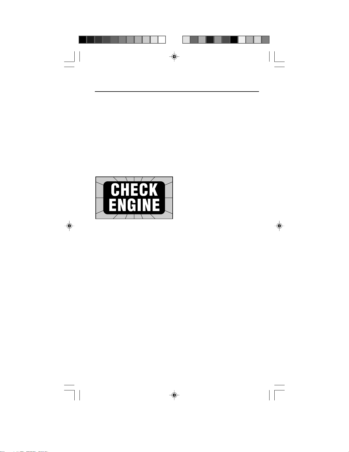
When to Read Codes
Use the Code Scanner to read computer
trouble codes if...
• The “Check Engine” light comes ON
when the engine is RUNNING
or,
• Vehicle engine is running poorly and
“Check Engine” light is OFF .
The Check Engine light
The engine computer turns the “Check
Engine” light on and off as needed.
This dashboard message light is either
amber or red and labeled:
– “Check Engine” or,
– “Service Engine Soon” or,
– “Service Engine Now” or,
– marked with a small engine picture.
Check Engine light: Normal
Operation
The “Check Engine” light is normally
OFF when the engine is RUNNING.
NOTE:
The light will come on when
ignition key is in ON position, but the
engine is OFF. (For example, before
you start the engine.) This is a normal
test of all the dashboard message
lights.
If the “Check Engine” light does not
come on, you have an electrical
problem which needs repair. Refer to
the “Diagnostic Circuit Check” steps in
the “Basic Diagnostic Procedures”
section of your vehicle service manual.
(Manual sources listed on page 4.)
Check Engine Light: Problem
Spotted!
Light ON and stays ON (when the
engine is RUNNING)
– The computer sees a problem that
does not go away. (A “hard” failure.)
– The light will stay on as long as the
problem is present.
– A trouble code is stored in computer
memory. (A “hard” code.)
– Use the Code Scanner at the earliest
convenient time to obtain codes.
Refer to section 3, “Reading Codes”.
Check Engine Light: Intermittent
Problem!
Light ON and then goes OFF (when
the engine is RUNNING)
– The computer saw a problem, but
the problem went away. (An
“intermittent” failure.)
– A trouble code is stored in computer
memory. (An “intermittent” code.)
– The light went out because the
problem went away, but the code
stays in memory.
– Use the Code Scanner at the
earliest convenient time to obtain
codes. Refer to Section 3, “Reading
Codes”.
NOTE:
The computer will automatically erase codes after several restarts
(typically 50) if the problem does not
return.
A Poorly Running Engine (No
Check Engine light)
Most likely this condition is not due to
computer system failures - but reading
codes can still be useful as part of a
basic troubleshooting procedure.
Review Section 4, “Using Codes”
before proceeding to Section 3,
“Reading Codes”.
7
Page 8
Reading Codes
Using the Code Scanner to Read Codes
1) Safety First!
• Set the parking brake.
• Put shift lever in PARK (automatic
transmission) or NEUTRAL
(manual transmission).
• Block the drive wheels.
• Make sure ignition key is in OFF
position.
2) Test the “Check Engine” Light
(Also called “Service Engine Soon”,
“Service Engine Now” or labeled
with a small engine picture.)
• Turn ignition key from OFF to ON
position, but do not start the
engine.
• Verify that the light turns on.
N
O
F
F
O
• If the light does not turn on, you
have a problem with this circuit
which must be repaired before
proceeding. Refer to the “Diagnostic Circuit Check” procedure in
your vehicle service manual. (See
manual listings on page 4.)
• Turn ignition key OFF.
3) Have a Pencil
and Paper
Ready
This is for
writing down
all the codes.
4)
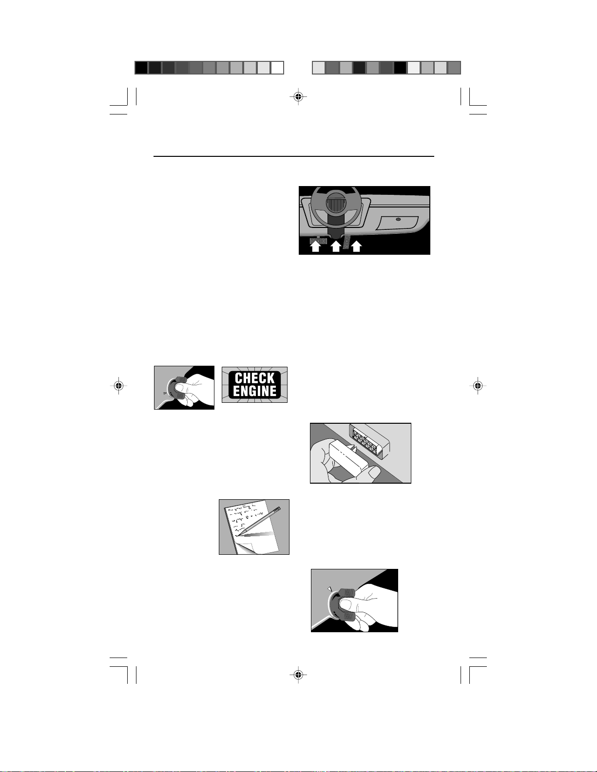
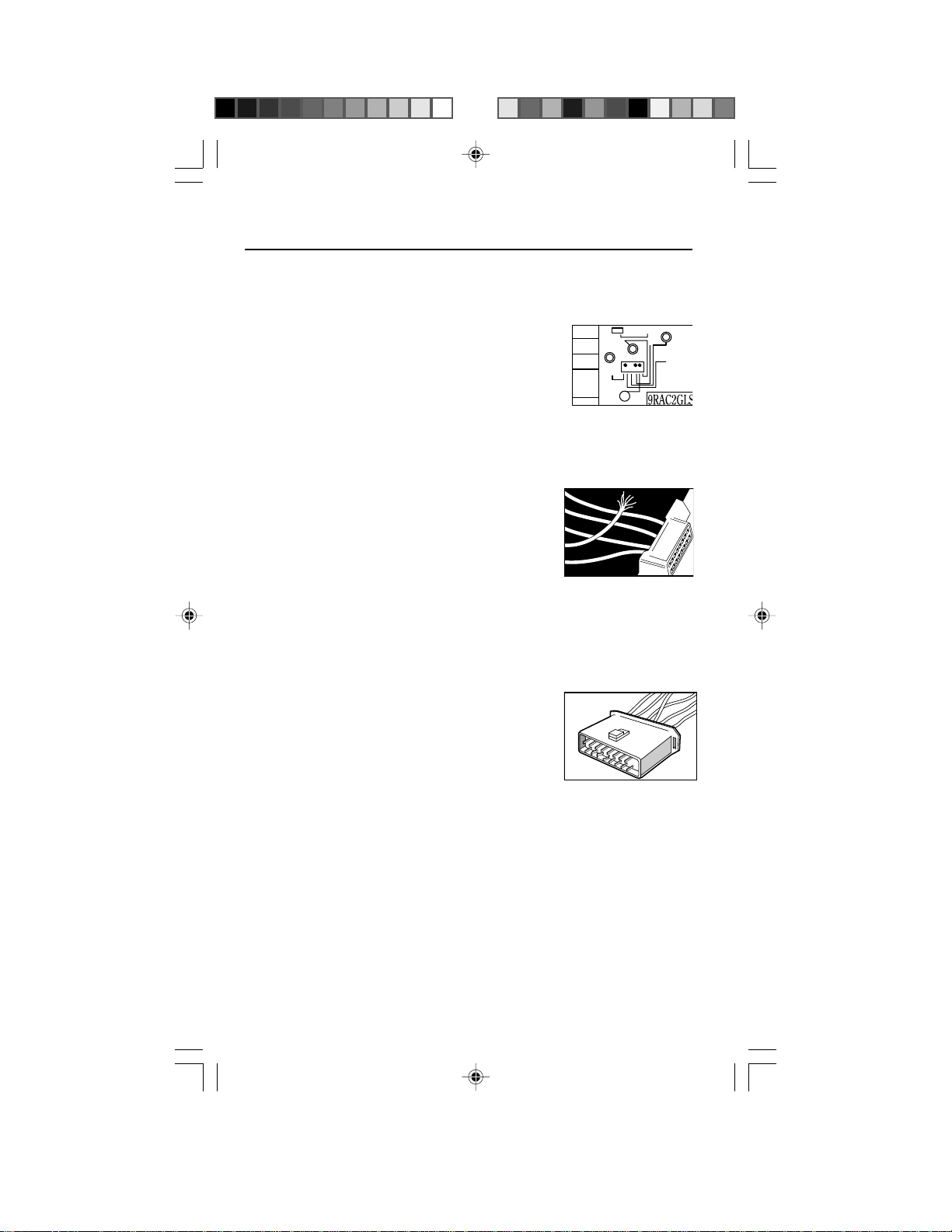
Find the Computer Test Connector
• Service manuals call this connec-
tor the Assembly Line Diagnostic
Link (ALDL) connector. It may also
be called the Assembly Line
Communication Link (ALCL) or
simply test connector.
• The connecter is located under the
dashboard on the driver’s side.
Exceptions:
–LeMans: Located behind passen-
ger side kick panel. Remove snapon cover for access.
–Fiero: Located in the center
console behind cover panel.
–Corvette: Sometimes located in
centerconsole behind ashtray.
Consult service manual for exact
location.
• The connector may be in full view, or
it may be recessed behind a panel.
An opening in the panel allows
access to recessed connectors.
• The connector may have a slip-on
cover labeled “Diagnostic
Connector.” Remove cover for
testing. Replace cover after
testing. Some vehicles require this
cover in place for proper operation.
5) Verify Ignition Key is OFF
F
O
F
N
O
8
Page 9
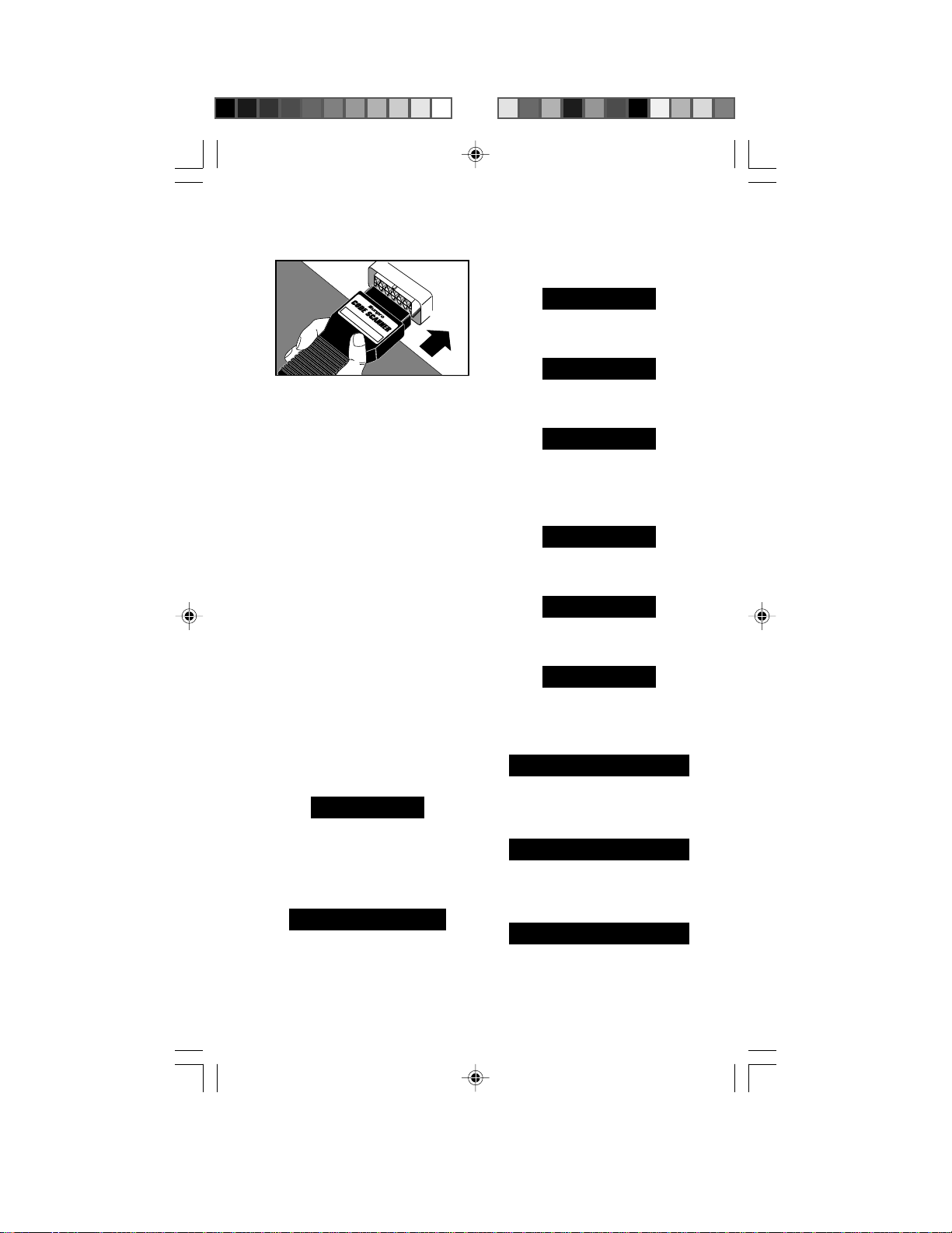
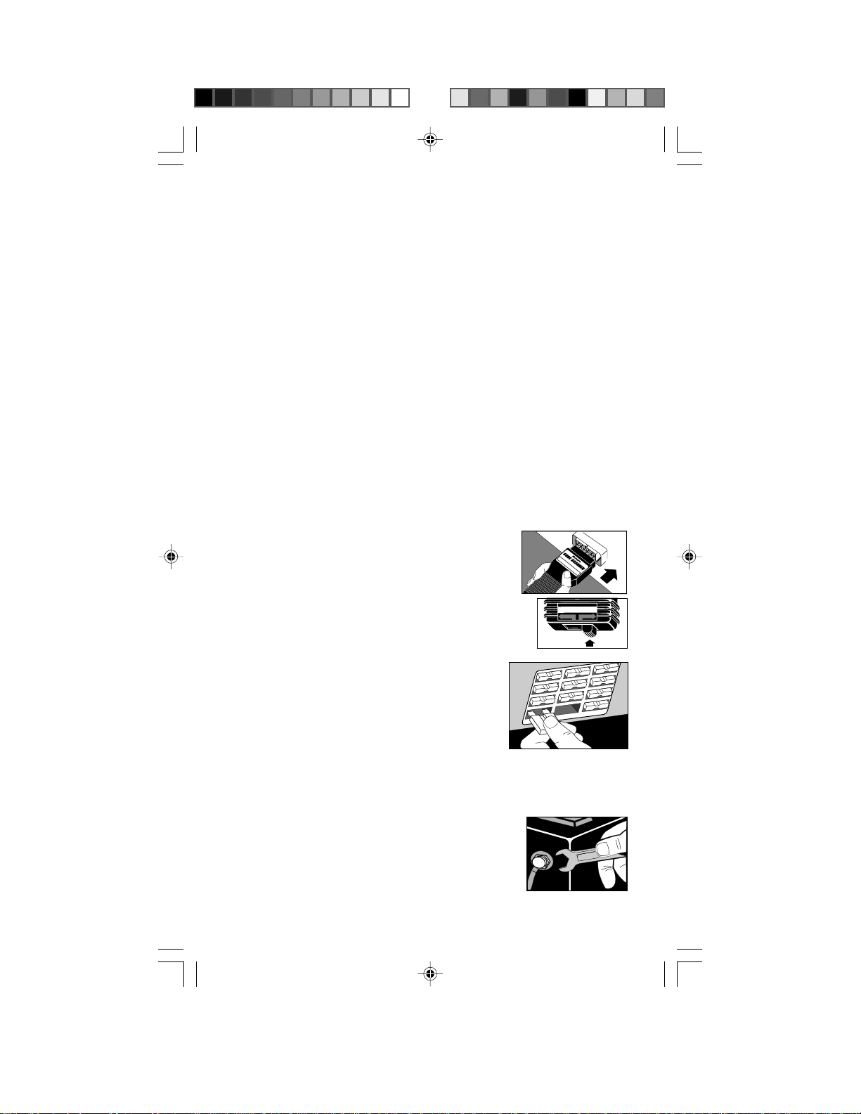
6) Plug the Code Scanner into the
Test Connector. Put TEST switch
on ENGINE.
sequence is repeated. This continues
until the ignition key is turned OFF (so
you can double check your code list).
Example of code 12 only:
Car Computer Code Reader
GM 1982 & higher - CP 9001
T
M
• The Code Scanner only fits ONE
WAY into the test connector.
• The Code Scanner will not harm
the vehicle engine computer.
NOTE: The Code Scanner does not
use all of the test connector
contacts. Also, one Code Scanner
pin may plug into an empty test
connector position. This is normal.
7) Turn Ignition Key to ON Position
but DO NOT START THE ENGINE
Y ou may hear some clicking sounds coming
from under the hood. This is normal.
WARNING: Stay away from the
radiator cooling fan! It may turn on.
8) Get Codes from the Flashing
“Check Engine” Light
NOTE: If the light does not flash, you
have a problem which must be
repaired before proceeding. Refer to
“Diagnostic Circuit Check” chart in
vehicle service manual.
Count flashes to get trouble codes.
Code 12 looks like:
PAUSE
❊
FLASH (pause) FLASH FLASH
(FLASH = 1, FLASH FLASH = 2.
Put 1 and 2 together = code 12.)
Code 23 looks like:
PAUSE
❊❊
FLASH FLASH (pause)
FLASH FLASH FLASH
• Each code is flashed three (3) times
before the next trouble code is sent.
• After all codes are sent, the whole
❊❊
❊❊❊
PAUSE
❊
FLASH (pause) FLASH FLASH
(longer pause)
PAUSE
❊
FLASH (pause) FLASH FLASH
(longer pause)
PAUSE
❊
FLASH (pause) FLASH FLASH
(even longer pause, then start over again)
Example of code series 12 and 24:
PAUSE
❊
FLASH (pause) FLASH FLASH
(longer pause)
PAUSE
❊
FLASH (pause) FLASH FLASH
(longer pause)
PAUSE
❊
FLASH (pause) FLASH FLASH
even longer pause, then go to next code)
PAUSE
❊❊
FLASH FLASH (pause)
FLASH FLASH FLASH FLASH
(longer pause)
PAUSE
❊❊
FLASH FLASH (pause)
FLASH FLASH FLASH FLASH
(longer pause)
PAUSE
❊❊
FLASH FLASH (pause)
FLASH FLASH FLASH FLASH
(even longer pause, then start all over
from the very beginning)
9
❊❊
❊❊
❊❊
❊❊
❊❊
❊❊
❊❊❊❊
❊❊❊❊
❊❊❊❊
Page 10

• A code 12 is always sent even
when the computer sees no
problem. This tells you the
computer diagnostic checks are
working properly. If you do not get
a code 12, or if the “Check Engine”
light does not flash you have a
problem which must be repaired.
Refer to “Diagnostic Circuit Check”
procedure in vehicle service
manual. (See manual listing on
page 4.)
• All codes are two (2) digits long.
• Codes are sent in numeric order
from the lowest number to the
highest.
Transmission Codes:
The engine computer can send trouble
codes for transmission problems - if
the vehicle has a computer controlled
transmission.
NOTE: Some diesel powered trucks
have a computer controlled transmission. These vehicles will only send
transmission related codes since the
the diesel itself is not computer
controlled.
• GM Vehicles
–The “Check Engine” light flashes
both engine codes and transmission codes.
• Saturn Vehicles
–The “Check Engine” light flashes
engine codes.
–The “Shift to D2” light flashes
transmission codes.
Look for a code 11 flashed on the
“Check Engine” light. This is a signal
telling you transmission codes will then
be flashed on the “Shift to D2” light.
Transmission codes are flashed in a
way similar to engine codes.
9) Turn Ignition Key OFF
10)
Remove Code Scanner and Reinstall Connector Cover, if
supplied.
The computer system is now back
to normal operation.
11)
Refer to “Test Results” chart on
page 9
This completes the code reading
procedure.
At this point you can either:
• Have your vehicle professionally
serviced. Trouble codes indicate
problems found by the computer.
or,
• Repair the vehicle yourself using
trouble codes to help pinpoint the
problem.
10
Page 11
TEST RESULTS COMMENTS
No indication on
“Check Engine”
light
or,
Did not receive
Code 12.
Code 12 only.
Received Code 12
along with other
codes.
• You have a problem which needs repair
before using the Code Scanner.
• Refer to “Diagnostic Circuit Check” chart
in vehicle service manual.
• Computer did NOT find a problem.
• If a driveability problem persists, perform
“Visual Inspection” and “Basic Mechanical
Checks” (Section 4, “Using Codes”.)
• Refer to “Diagnosis by Symptom” charts in
vehicle service manual. (Additional
electrical and mechanical checks are
listed.)
• Computer found problems in vehicle.
• Follow steps in Section 4, “Using Codes”.
• Code definitions are in Section 5, “Code
Meanings”.
– GM engine and transmission codes start
on page 14.
– Saturn engine codes start on page 14.
• Saturn vehicles only: Code 11 means
transmission codes are flashed on “Shift
to D2” light.
– Saturn transmission codes start on
page 19.
11
Page 12
Using Codes
Using Trouble Codes as Part of a Basic
Troubleshooting Procedure
A driveability problem can have many
possible causes which are not related
to the computer system. Reading
codes is one part of a good troubleshooting procedure consisting of:
1) Visual Inspection
2) Basic Mechanical Checks
3) Reading Codes
4) Using the Vehicle Service Manual
5) Erasing Codes
1) Visual Inspection
Doing a thorough visual and “handson” underhood inspection before
starting any diagnostic procedure is
essential!
You can find the cause of many
drivability problems by just looking,
thereby saving yourself a lot of time.
• Are routine maintenance items
O.K.?
– Clean air filter
– Correct fluid levels
– Recommended tire pressure
– Good ignition system components
- spark plugs, wires and the like.
• Has the vehicle been serviced
recently?
– Sometimes things get recon-
nected in the wrong place, or not
at all.
• Don’t take shortcuts.
– Inspect hoses and wiring which
may be difficult to see because of
location beneath air cleaner
housings, alternators and similar
components.
• Inspect all vacuum hoses for:
–Correct routing. (Hoses may be
missing or misconnected.) Refer
to vehicle service manual, or
Vehicle Emission Control
HVAC
Information
(VECI)
decal
located in
the engine
compart-
YST
CE BOOSTER
G GAP
U.S.A.
EM
CRUISE
EGR
VAC
REG
FUEL
PRESS
REG.
EGR
VAC
REG
ment.
–Pinches and kinks.
–Splits, cuts or breaks.
• Inspect wiring for:
–Contact
with sharp
edges.
(This
happens
often.)
–Contact
with hot
surfaces, such as exhaust
manifolds.
–Pinched, burned or chafed
insulation.
–Proper routing and connections.
• Check
electrical
connectors
for:
–Corrosion
on pins.
–Bent or
damaged pins.
–Contacts not properly seated in
housing.
–Bad wire crimps to terminals.
Problems with connectors are
common in the engine control system.
Inspect carefully. Note that some
connectors use a special grease on
the contacts to prevent corrosion. Do
not wipe off! Obtain extra grease, if
needed, from your vehicle dealer. It is
a special type for this purpose.
12
BRAKE BOOSTER
FRONT
OF CAR
TO TRANS
MODE
Page 13
2) Basic Mechanical Checks
Don’t overlook the basic checks listed
on the next page. Mechanical problems
by themselves can always create engine
troubles. Even worse, these problems
can make a good sensor send an
incorrect signal to the computer. Then
the computer runs the engine improperly or sets a trouble code.
• Cylinder compression:
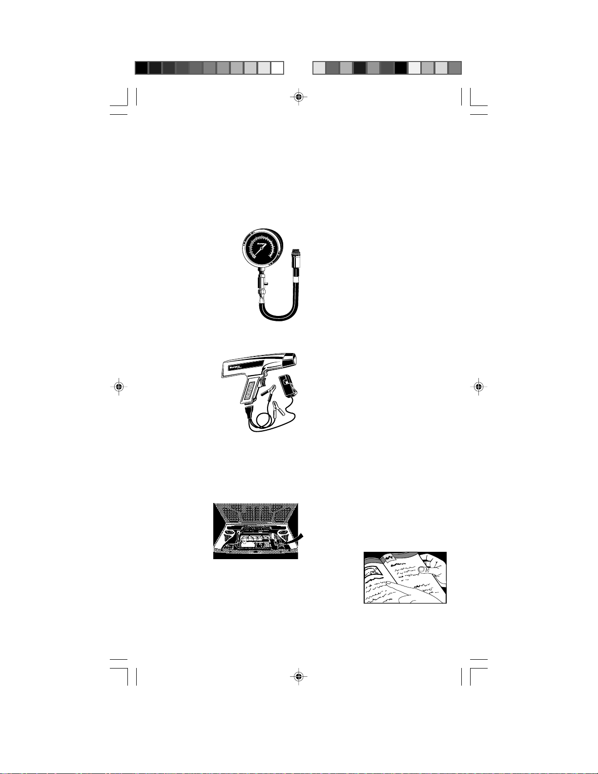
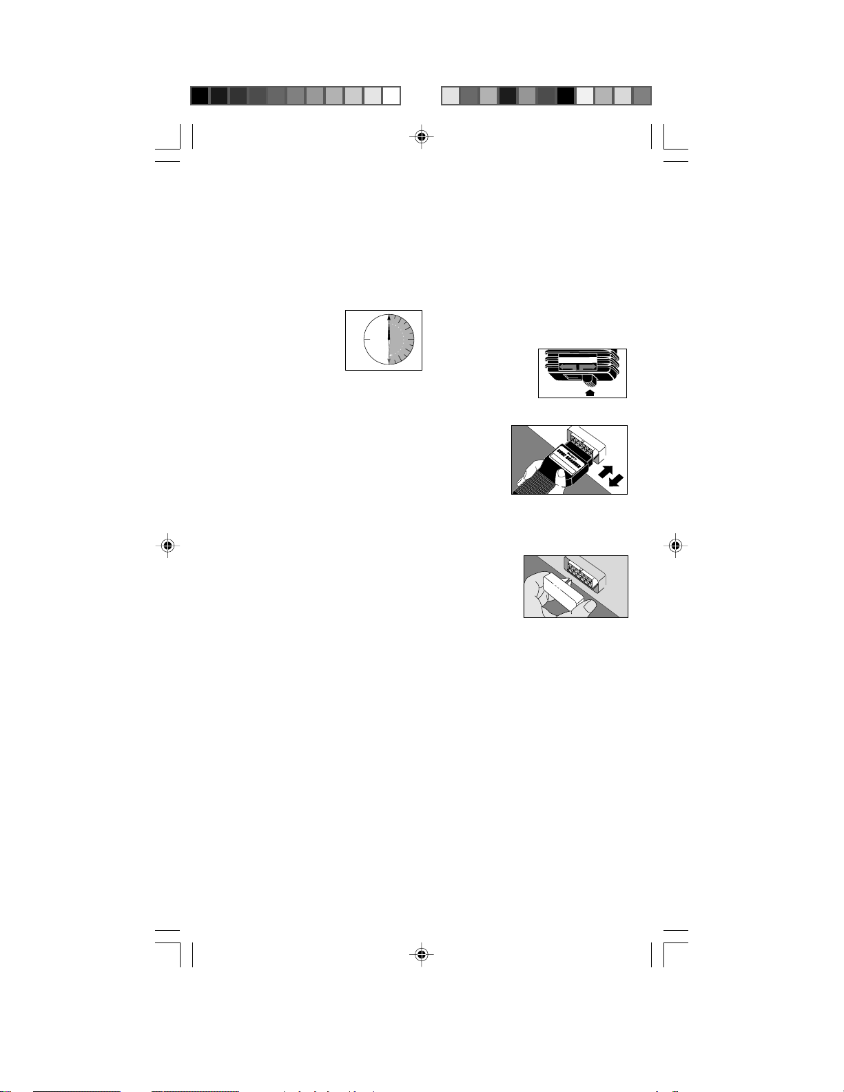
150
–Check for proper
compression in
each cylinder.
–Refer to vehicle
180
120
210
9
12
90
®
240
6
15
60
3
18
30
COMPRESSION
TESTER
21
270
300
service manual for
specifications.
• Exhaust backpressure:
–Check for any
restrictions in the
exhaust system.
• Ignition timing (If adjustable):
–Verify timing is within
specification.
–Refer to
by
INDUCTIVE TIMING LIGHT
.
A
.
S
.
U
in
e
d
a
M
CP7515
vehicle
service manual,
or Vehicle
Emission Control
Information
(VECI) decal
located in the
engine compartment.
–Be sure to disable computer spark
advance timing circuit, if used,
when checking basic timing!
• Air induction system:
–Check for
intake
manifold
vacuum
leaks.
–Check for
carbon or
varnish
build-up on throttle valve or idle
speed control device.
3) Read Codes
Refer to Section 3, “Reading Codes”.
Remember there are two types of
codes:
• “Hard” codes – codes for problems
which are present now.
• “Intermittent” codes – codes for
problems which happened in the
past, but are not happening now.
Remember...
–“Check Engine” light ON: You have
at least one “hard” code stored in
memory. (You may have more
“hard” or “intermittent” codes
stored, also.)
– “Check Engine” light OFF: Stored
codes are for “intermittent”
problems. (Exception: sometimes
there are minor “hard” faults which
do not turn on the “Check Engine”
light.)
How to Tell “Hard” Codes from
“Intermittent” Codes
Do the following if you are not sure:
• Write down all codes (except code
12). For example: 15, 34.
• Erase codes from computer
memory. (Refer to Step 5.)
• Drive vehicle for at least 10 minutes
at normal temperature, cruise speed
and load. (The computer may want
to verify a fault for several minutes
before storing a code.)
• Read codes again. Codes which
return are “hard” faults. Codes which
do not return are “intermittent” faults.
For example, if you see code 15 (but
not 34) then you know code 15 is a
“hard” code and code 34 was
“intermittent”.
Y ou troubleshoot the “hard” problems
differently from the “intermittent” ones.
4) Use Vehicle Service Manual
Dealing with “Hard” Codes
• Refer to
the vehicle
service
manual
diagnostic
code
charts.
These will be in Section 6E in the
GM manual. Other publications have
this information in books or sections
13
Page 14
called “Computerized Engine
T
M
GM 1982 & higher - CP 9001
C
a
r
C
o
m
p
u
t
e
r
C
o
d
e
R
e
a
d
e
r
Controls”, “Electronic Engine
Controls” or “Tune-Up Information.”
• Follow all the steps in the diagnostic
procedure for the trouble code.
• Be sure to erase the trouble codes
from computer memory after
completing repair work. (See Step 5,
“Erasing Codes from Computer
Memory”.)
• Drive vehicle for at least 10 minutes
at normal temperature, cruise speed
and load.
– Read codes again to verify trouble
code is gone (problem fixed). Other
codes may have been repaired at
the same time!
Dealing with No Trouble Codes
Have a driveability problem, but only
get code 12? Make sure you do Step
1, “Visual Inspection” and Step 2,
“Basic Mechanical Checks”. If you did
not find the problem, then refer to
“Diagnosis by Symptom” charts in
vehicle service manual.
5) Erasing Codes from Computer
Memory
Erase codes from memory whenever
you complete a repair or to see if a
problem will occur again. Note: The
computer will automatically erase
codes after several restarts (typically
50) if the problem does not return.
Dealing with “Intermittent” Codes
These codes are for problems which
happened in the past, but are not
present now.
• Usually these problems are due to
loose connections or bad wiring.
The problem cause can often be
found with a thorough visual and
“hands-on” inspection. (Refer to
Step 1, “Visual Inspection”.)
• Refer to the vehicle service manual
diagnostic code section. Y ou can not
use the code chart procedures
because they are for “hard”
problems - those which are present
now. However , the charts have
suggestions for dealing with
intermittents and can tell you where
bad connections, etc., might exist.
Y ou can also refer to the “Diagnosis
by Symptom” charts.
• Be sure to erase the trouble codes
from computer memory after
completing repair work. (See Step 5,
“Erasing Codes from Computer
Memory”.)
• Drive vehicle for at least 10 minutes
at normal temperature, cruise speed
and load.
– Read codes again to verify trouble
code is gone (problem fixed).
Other codes may have been
repaired at the same time!
GM
Proceed as follows:
• Observe all safety precautions. (See
page 2.)
• Turn ignition key ON.
• Insert Code
Scanner.
Make sure
TEST switch
is in ENGINE
position!
• Turn ignition key
OFF.
• Remove the
ECM fuse
from the
fuse block
for 10
seconds.
• Replace
fuse.
• Remove
Code Scanner.
If ECM fuse cannot be located, then –
• Disconnect power to the computer.
To do this:
–Disconnect
the positive
battery
terminal
“pigtail”,
OR
TEST
ABS
ENGINE
14
Page 15
TEST
ABS
ENGINE
–Open the in-line fuse holder going
to the positive battery terminal,
OR
–Disconnect negative battery
terminal – but this will also erase
other items too, such as digital
clock settings and preset digital
radio tuning.
• All the trouble codes are now
erased from computer memory!
• Wait thirty (30)
seconds.
• Reconnect power
30
SECONDS
to the computer.
IMPORTANT: The
computer has a “learning” ability to
take care of minor variations in engine
control operation. Whenever you erase
the computer memory by disconnecting power, the computer has to
“relearn” various things. Vehicle
performance may be noticeably
different until it “relearns.” This
temporary situation is normal. The
“learning” process takes place during
warm engine driving.
SATURN
Use the GM method, or proceed as
follows:
• Observe all safety precautions. (See
page 2.)
Warning: Stay away from the
engine cooling fan. It may turn on
during this procedure.
• Turn ignition key ON, but DO NOT
ST ART THE
ENGINE.
• Put TEST switch
on ENGINE.
• Plug and
unplug the Code
Scanner
into the
test
connector
3 times
within 5
seconds.
• All the trouble codes are now
erased from computer memory!
• Turn ignition key OFF.
• Remove
Code
Scanner and
re-install
connector
cover, if
supplied.
Car Computer Code Reader
GM 1982 & higher - CP 9001
T
M
NOTE:
• The engine control computer is
usually called ECM (Engine Control
Module) or PCM (Powertrain Control
Module) in the vehicle service
manuals.
• Information flags and “Intermittent”
codes may not by erased using this
procedure. The presence of these
codes will not cause any driveability
or future self-diagnostics problems.
15
Page 16

Code Meanings
Note:
• Code meanings can
vary with vehicle,
model year, engine
type and options.
• If a code number has
more than one
definition listed, note
that that only one
definition applies to
your vehicle. Consult
service manual to get
the specific definition
and troubleshooting
procedure for your
vehicle.
• Follow vehicle service
manual procedures to
find the cause of the
code.
Remember:
1) Visual inspections are
important!
2) Problems with wiring
and connectors are
common, especially
for intermittent faults.
3) Mechanical problems
(vacuum leaks,
binding or sticking
linkages, etc.) can
make a good sensor
send an incorrect
signal to the computer.
This can cause a
Trouble Code.
4) Incorrect information
from a sensor may
cause the computer to
control the engine in
the wrong way. Faulty
engine operation
could even make a
different good sensor
send an incorrect
signal to the computer
and generate more
trouble codes!
Code lists:
This page: (Codes from
flashing “Check Engine”
light.)
• GM engine codes
• GM electronic
transmission codes
• Saturn engine codes
Page 19 (Codes from
flashing “Shift to D2”
light.)
• Saturn electronic
transmission codes
Refer to Section 4,
“Using Codes” for
troubleshooting tips and
steps to erase codes
from computer memory.
GM/Saturn Engine Codes, GM Transmission Codes
(Saturn transmission code list begins on page 19)
11
Transaxle codes present
(Saturn).
Whenever code 11 is sent,
it means transmission
codes will be flashed next
on the “Shift to D2” light.
Refer to page 19 for Saturn
transmission code list.
12
Diagnostic test is working
properly. (Engine computer
verifies no RPM Reference
Pulses are present during
engine off testing.)
13
Oxygen (O2) sensor signal stays low (“lean”)
during warm engine cruise
or sensor circuit is open or
left sensor circuit is open
(dual sensor models).
14
Coolant temperature
sensor (CTS) - signal
voltage is low.
15
Coolant temperature
sensor (CTS) - signal
voltage is high.
16
Battery or alternator problem
- voltage too high or low.
OR
Direct ignition system
(DIS) fault - line open or
shorted to ground.
OR
Ignition system fault - Loss
of 2X or Low Resolution
Pulse signal.
OR
Transmission speed error.
16
17
RPM signal problem.
OR
Camshaft sensor - circuit
problems.
OR
Electronic Control Module
(ECM) computer circuit
problem - Pull-up resistor
(Saturn).
18
Camshaft or Crankshaft
sensor - circuit problems.
OR
Fuel Injector circuit is not
working properly - possible
blown fuel injector fuse.
19
Ignition system fault Intermittent 7X signal or
loss of 58X signal or 6X
signal (Saturn).
Page 17

21
Throttle position sensor
(TPS) - signal voltage is
high during engine idle or
deceleration.
22
Throttle position sensor
(TPS) - signal voltage is
low during engine idle.
OR
Fuel cutoff relay circuit open or shorted to ground.
23
Manifold air temperature
(MAT) sensor - signal
voltage is low or high.
OR
Throttle position sensor
(TPS) error.
OR
Mixture Control (M/C)
solenoid - open or short
circuit problems.
24
Vehicle speed sensor
(VSS) - open or short
circuit problems.
25
Manifold air temperature
(MAT) sensor - signal
voltage is low.
OR
Vacuum switching valve
circuit - open or shorted to
ground.
OR
ATS sensor - signal
voltage is high.
26
Quad-Driver module or
Quad-driver No. 1 error.
27
2nd gear switch.
OR
Quad-Driver module or
Quad-driver No. 2 error.
28
3rd gear switch.
OR
Quad-Driver module or
Quad-driver No. 3 error
(Corvette).
OR
(Transmission) Fluid
pressure switch assembly
- open or short circuit
problems.
29
4th gear switch.
OR
Quad-Driver module or
Quad-driver No. 3 error.
OR
Secondary air injection
system - circuit problems.
31
Manifold absolute pressure
(MAP) sensor - signal
voltage is low.
OR
Fuel injector.
OR
Park/Neutral switch circuit problems.
OR
CAM sensor - circuit
problems.
OR
Engine speed control
governor malfunction.
(Van)
OR
Turbocharger wastegate
overboost.
OR
Wastegate electrical signal
- open or shorted to
ground.
OR
Purge solenoid voltage
high (carburetor engines)
32
Barometric pressure (BARO)
sensor circuit failure.
OR
Exhaust gas recirculation
(EGR) valve diagnostic
switch - closed during
engine start-up or open
when EGR flow requested
by ECM.
OR
EGR/EVRV.
33
Mass air flow (MAF)
sensor - signal voltage or
frequency is high during
engine idle.
OR
Manifold absolute pressure
(MAP) sensor - signal
voltage is high during
engine idle. (Note: Engine
mis-fire or unstable idle
may cause this code.)
17
34
Mass air flow (MAF) sensor
- signal voltage or
frequency is low during
engine cruise.
OR
Manifold absolute pressure
(MAP) sensor - signal
voltage is low during
ignition on.
OR
Pressure sensor circuit signal voltage too high or
low (carburetor engines).
35
Idle air control (IAC)
system problem - can not
set desired RPM.
36
Mass air flow (MAF) sensor
- burn-off circuit problem.
OR
Transmission shift problem
(electronically controlled
transmissions only).
OR
Direct ignition system (DIS)
fault - loss of 24X signal or
extra or missing pulses in
electronic spark timing
(EST) signal.
OR
Ignition system fault - loss
of High Resolution Pulse
signal.
37
Brake switch stuck “on”.
38
Brake switch circuit fault.
OR
Knock sensor (KS) - open
circuit problem.
39
Torque converter clutch
(TCC) circuit fault.
OR
Clutch switch circuit
problems.
OR
Knock sensor (KS) - short
circuit problem.
Page 18

41
Cam sensor (CAM) failure.
OR
Cylinder select error.
OR
Tach input error - no
reference pulses during
engine run.
OR
Electronic spark timing
(EST) circuit - open or
shorted to ground during
engine run.
OR
Direct ignition system
(DIS) fault - bypass circuit
open or shorted to ground
during engine run.
OR
Ignition system fault - loss
of 1X Reference Pulse
signal.
42
Electronic spark timing
(EST) circuit - open or
shorted to ground during
engine run.
OR
Direct ignition system
(DIS) fault - bypass circuit
open or shorted to ground
during engine run.
OR
Fuel cutoff relay circuit open or shorted to ground.
43
Electronic spark timing
(EST) circuit - low voltage
detected.
OR
Electronic spark control
(ESC) - circuit problems.
44
Lean exhaust indication oxygen (O
stays low after one or two
minutes of engine run.
(Left sensor on dual
sensor engines.)
) sensor voltage
2
45
Rich exhaust indication oxygen (O
stays high after one minute
of engine run. (Left sensor
on dual sensor engines.)
) sensor voltage
2
46
Vehicle anti-theft system
(VATS) failure.
OR
Power steering pressure
switch failure.
47
Electronic control module
(ECM) computer circuit
problems - universal
asynchronous receiver/
transmitter (UART) link or
data loss.
OR
Knock sensor module
located in the computer is
not working properly.
48
Misfire symptom.
OR
Mass air flow (MAF)
sensor - open or short
circuit MAF sensor signal.
49
High idle RPM or vacuum
leak (Saturn).
51
Electronic control module
(ECM) computer circuit
problems - faulty
programmable read-only
memory (PROM), MEMCAL, ECM or checksum
errors.
52
Electronic control module
(ECM) computer circuit
problems - faulty or missing
CALPAC or MEM-CAL,
analog to digital converter
(A/D) error or Quad-Driver
module (QDM) fault.
OR
Oil temperature sensor signal voltage is low
(Corvette).
OR
System voltage high for a
long period of time.
(Electronic transmission
note: this fault may cause
other codes to be set.)
53
Over voltage condition.
(Electronic transmission
note: this fault may cause
other codes to be set.)
OR
Exhaust gas recirculation
(EGR) - system problems
or EGR Solenoid No.1
problem.
OR
18
Voltage reference error.
OR
Vehicle anti-theft system
(VATS) problems.
54
Low fuel pump voltage.
OR
Fuel pump relay.
OR
EGR Solenoid No. 2
failure.
OR
Quad-Driver module
(QDM) output failure.
OR
Mixture Control (M/C)
solenoid - circuit voltage
too high.
55
Electronic control module
(ECM) computer circuit
problems - ECM failure,
serial bus error, SAD error
or fuel lean malfunction.
OR
EGR Solenoid No. 3
failure.
56
Corrosivity/add coolant.
OR
Port throttle system
vacuum sensor problems.
OR
Quad-Driver “B” fault.
57
Boost Control problem.
58
Vehicle anti-theft system
(VATS) problem.
OR
Transmission Temperature
Sensor (TTS) - short circuit
problem in sensor or
wiring.
OR
Transmission fluid
temperature high.
59
Transmission Temperature
Sensor (TTS) - open circuit
problem in sensor,
connector or wiring.
OR
Transmission fluid
temperature low.
Page 19

61
Oxygen (O2) sensor
degraded.
OR
Port throttle system error.
OR
Cruise control problems vent solenoid circuit.
OR
Air Conditioner (A/C)
system performance
problems.
62
Gear switch circuit
problems.
OR
Oil temperature sensor signal voltage is high
(Corvette).
OR
Cruise control problems vacuum solenoid circuit.
63
Manifold absolute pressure
(MAP) sensor - signal
voltage is high.
OR
Small EGR failure.
OR
Right oxygen (O2) sensor
failure (dual sensor
engines).
OR
Cruise control system
problem.
64
Manifold absolute pressure
(MAP) sensor - signal
voltage is low.
OR
Medium EGR failure.
OR
Right oxygen(O2) sensor lean condition indicated
(dual sensor engines).
65
Large EGR failure.
OR
Fuel injector current low.
OR
Right oxygen (O2) sensor rich condition indicated
(dual sensor engines).
OR
Cruise control position
sensor problem.
66
Air Conditioner (A/C)
pressure sensor - circuit
problems or low A/C charge.
OR
Electronic Control Module
(ECM) computer circuit
problem - internal reset
occurred.
OR
(Transmission) 3-2 shift
control solenoid - circuit
problems.
67
Cruise control - switch
circuit problems.
OR
Air Conditioner (A/C)
pressure sensor - circuit
problems.
OR
Torque Converter Clutch
(TCC) solenoid - circuit
problems.
OR
Cruise control switches circuit problems.
68
Cruise control - system
circuit problems.
OR
Air Conditioner (A/C)
clutch relay - short circuit.
OR
(Transmission) Overdrive
ratio error - engine RPM
greater than input speed.
69
Air Conditioner (A/C)
system - pressure switch
or A/C clutch relay circuit
problems.
OR
Torque converter clutch
stuck “on”.
70
Air Conditioner (A/C)
pressure sensor - signal
voltage too high.
71
Air Conditioner (A/C)
evaporator temperature
sensor - signal voltage too
low.
72
Gear Select switch - circuit
problems.
OR
19
Vehicle Speed Sensor
(VSS) - loss of signal.
73
Air Conditioner (A/C)
evaporator temperature
sensor - signal voltage too
high.
OR
(Transmission) Pressure
control solenoid - circuit
problems.
74
Traction control circuit
voltage low.
75
Exhaust gas recirculation
(EGR) system - Solenoid
No.1 problem.
OR
System voltage low charging system problems.
OR
Transmission voltage low low system voltage
possibly caused by
generator voltage supply
circuit or power train
control module (PCM).
76
Exhaust gas recirculation
(EGR) system - Solenoid
No.2 problem.
77
Exhaust gas recirculation
(EGR) system - Solenoid
No.3 problem.
OR
Primary cooling fan relay
driver circuit - circuit
problems.
78
Secondary cooling fan
relay driver circuit - circuit
problems.
79
Vehicle Speed Sensor
(VSS) - signal voltage too
high.
OR
Transmission Temperature
Sensor (TTS) - high
temperature indicated.
80
Vehicle Speed Sensor
(VSS) - signal voltage too
low.
Page 20
81
Brake switch circuit
problems.
OR
Anti-Lock Brake System
(ABS) message fault
(Saturn).
OR
(Transmission) Solenoid
“B” (3-2 shift solenoid) open or short circuit
problems.
82
Ignition system fault - 3X
signal problem.
OR
Electronic control module
(ECM) computer circuit
problem - internal
communications failure
(Saturn).
OR
(Transmission) Solenoid
“A” (1-2 shift solenoid) open or short circuit
problems.
83
Torque Converter Clutch
(TCC) solenoid - circuit
problems.
OR
Reverse Inhibit - open or
short circuit in reverse
inhibit solenoid coil.
84
3-2 Control solenoid - open
or short circuit problems.
OR
Skip shift solenoid - open
or short circuit problems.
85
Electronic control module
(ECM) computer circuit
problems - faulty
programmable read-only
memory (PROM).
OR
(Transmission) Input or
output speed sensor circuit problems. (Speed
sensor signals do not
agree with with selected
gear range.)
OR
Torque converter clutch
(TCC) - TCC is
mechanically stuck on.
86
Electronic control module
(ECM) computer circuit
problems - faulty analogto-digital (A/D) converter.
OR
(Transmission) Low gear
error - transmission in 3rd
or 4th gear when computer
commanding 1st or 2nd
gear.
87
Electronic control module
(ECM) computer circuit
problems - faulty
electrically erasable
programmable read-only
memory (EEPROM).
OR
(Transmission) High gear
error - transmission in 1st
or 2nd gear when
computer commanding 3rd
or 4th gear.
88
Electronic control module
(ECM) computer circuit
problem - internal reset
occurred.
91
Skip shift light - open or
short circuit problems in
skip shift light circuit.
93
Pressure control solenoid transmission line pressure
not at desired level.
95
Change oil light - wrong
voltage is present in light
circuit for more than 26
seconds.
96
Transmission voltage low low system voltage
possibly caused by
generator voltage supply
circuit or power train
control module (PCM).
OR
Low oil light - wrong
voltage is present in light
circuit for more than 26
seconds.
97
Vehicle speed sensor
(VSS) - output circuit
problems.
99
Tachometer output circuit
problems.
20
Page 21

Saturn Transmission Codes
(GM/Saturn engine codes and GM transmission code list begins on page 14.)
Note: Code numbers
labeled “Information
Flag” may be sent along
with the regular
(unlabeled) trouble
codes. The computer
sends Information Flags
to help you find the
cause of a trouble code.
Note that conditions
which only cause an
Information Flag will not
turn on the “Check
Engine” light. Refer to
vehicle service manual
troubleshooting charts.
13
(Information Flag)
Line pressure high.
14
(Information Flag)
Line pressure low.
15
(Information Flag)
Hot light.
16
No 1st gear.
OR
(Information Flag)
Electrical variable orifice
(EVO) fault.
18
(Information Flag)
No gears available.
21
2nd gear stuck “on”.
22
No 2nd gear.
23
No 3rd gear.
24
No 4th gear.
25
No torque converter clutch.
26
Torque converter clutch
stuck”on”.
27
(Information Flag)
Quick quad-driver output
fault - open or short circuit
on any of the qaud-driver
module circuits (QDM) that
lasts 5 seconds or longer.
31
Transaxle temperature
circuit open.
32
Transaxle temperature
circuit grounded.
34
(Information Flag)
Powertrain Control Module
(PCM) computer circuit
problem - communications
failure.
35
No turbine speed signal.
36
Turbine speed signal
noise.
41
Vehicle Speed Sensor
(VSS) circuit - no signal.
42
Vehicle Speed Sensor
(VSS) circuit - signal noise.
43
(Information Flag)
Master relay - open or
grounded.
44
(Information Flag)
Master relay - shorted.
45
(Information Flag)
Gear selector switch circuit
problem - no signal.
46
(Information Flag)
Gear selector switch circuit
problem - invalid signal.
21
47
(Information Flag)
Powertrain Control Module
(PCM) computer circuit
problem - communication
interrupt failure.
48
Hold mode voltage is too
low.
OR
(Information Flag)
Reference input
intermittent or noisy missing or extra ignition
reference pulses are
detected by powertrain
control module (PCM).
49
(Information Flag)
Gear selector error signal.
51
(Information Flag)
Powertrain Control Module
(PCM) computer circuit
problem - serial link data
invalid.
52
Hold mode stuck “on”.
OR
(Information Flag)
Battery voltage out of
range - battery voltage has
dropped below 11 volts or
has increased above 17
volts.
53
Hold mode stuck “off”.
OR
(Information Flag)
ESC (Knock present) powertrain control module
(PCM) can not reduce
engine knock by retarding
timing.
54
Powertrain Control Module
(PCM) computer circuit
problem - analog to digital
(A/D) converter error.
OR
(Information Flag)
5-volt reference ground flag will set if manifold
Page 22

absolute pressure (MAP)
sensor signal, handwheel
sensor signal, throttle
position sensor (TPS)
signal are zero volts.
55
Transaxle temperature
sensor failure.
56
(Information Flag)
Generic Field-Effect
Transistor (FET) driver
failure.
57
(Information Flag)
Powertrain Control Module
(PCM) computer circuit
problem - non volatile
Random Access Memory
(RAM) failure.
58
(Information Flag)
Battery voltage unstable battery voltage changes
more than 3 volts
instantaneously.
61
(Information Flag)
Powertrain Control Module
(PCM) computer circuit
problem - Programmable
Read-Only Memory
(PROM) failure.
OR
(Information Flag)
6X Signal fault - 6X pulses
do not occur between
each reference pulse or a
6X pulse does not
immediately follow a
reference pulse. Possible
open or intermittent in DIS
module harness.
62
(Information Flag)
Powertrain Control Module
(PCM) computer circuit
problem - interrupt failure.
63
(Information Flag)
Powertrain Control Module
(PCM) computer circuit
problem - Random Access
Memory (RAM) failure.
OR
(Information Flag)
Option check sum error flag will be set if tire size
and options do not
compare with those stored
in the powertrain control
module (PCM).
64
(Information Flag)
Powertrain Control Module
(PCM) computer circuit
problem - Electrically
Erasable Programmable
Read-Only Memory (EE
PROM) failure.
65
(Information Flag)
Ignition voltage problem too high or low.
66
(Information Flag)
Clamp shorted.
67
(Information Flag)
Clamp open.
OR
(Information Flag)
Handwheel sensor circuit
fault - handwheel sensor
output voltage is out of
tolerance.
68
(Information Flag)
Line circuit grounded or
open.
69
(Information Flag)
Line circuit shorted.
71
(Information Flag)
2nd line circuit - grounded
or open.
OR
(Information Flag)
Cooling system high
temperature - engine
coolant temperature is
greater than 239°F
(118°C).
72
(Information Flag)
2nd line circuit - shorted.
OR
(Information Flag)
Cooling system low
temperature - engine
coolant temperature is less
than 32°F (0°C).
73
(Information Flag)
3rd line circuit - grounded
or open.
OR
(Information Flag)
Coolant sensor signal
unstable - coolant
temperature sensor (CTS)
indicates a change of more
than 59°F (15°C)
instantaneously.
74
(Information Flag)
3rd line circuit - shorted.
OR
(Information Flag)
Coolant/Transmission
temperature sensor ratio
error - indicates a degrading
coolant temperature sensor
(CTS) if transmission
temperature sensor (TTS) is
working properly.
75
(Information Flag)
3rd gear stuck “on”.
OR
(Information Flag)
Air temperature sensor
signal unstable - air
temperature sensor (ATS)
indicates a change of more
than 59°F (15°C)
instantaneously.
22
Page 23

76
(Information Flag)
4th line circuit - grounded
or open.
OR
(Information Flag)
Throttle position sensor
(TPS) to manifold absolute
pressure (MAP) sensor
voltage out of range - flag
is set if TPS and MAP
voltage readings dont
agree with internal
relational tables stored in
the powertrain control
module (PCM).
77
(Information Flag)
4th line circuit - shorted.
78
(Information Flag)
4th gear stuck “on”.
79
(Information Flag)
Torque Converter Clutch
(TCC) circuit - grounded or
open.
81
(Information Flag)
Torque Converter Clutch
(TCC) circuit - shorted.
82
(Information Flag)
Transaxle temperature
unstable.
83
(Information Flag)
Transaxle temperature
low.
OR
(Information Flag)
Low coolant - coolant
switch opens for 20
seconds with engine
running.
84
(Information Flag)
Brake switch stuck open.
85
(Information Flag)
Brake switch stuck closed.
86
(Information Flag)
Engine speed invalid.
87
(Information Flag)
Torque Converter Clutch
(TCC) hold circuit grounded or open.
88
(Information Flag)
Torque Converter Clutch
(TCC) hold circuit shorted.
89
(Information Flag)
Master relay stuck “on”.
91
(Information Flag)
Assembly Line Diagnostic
Link (ALDL) - serial
communication link
interrupt.
92
(Information Flag)
Clamp circuit - intermittent
fault.
93
(Information Flag)
Torque Converter Clutch
(TCC) hold circuit intermittent fault.
94
(Information Flag)
Master enable relay circuit
- intermittent fault.
95
(Information Flag)
Line circuit - intermittent
fault.
96
(Information Flag)
Torque Converter Clutch
(TCC) circuit - intermittent
fault.
97
(Information Flag)
2nd gear circuit intermittent fault.
98
(Information Flag)
3rd gear circuit intermittent fault.
99
(Information Flag)
4th gear circuit intermittent fault.
23
Page 24
Other Features
Additional Code Scanner Diagnostic Features
This section contains...
Relay and Solenoid Circuit T est:
You
can switch on most of the computer
controlled relay and solenoid circuits for checking relay operation or making
wiring voltage checks.
Field Service T est (Fuel Injected
Engines Only):
A quick check of the
fuel control system to verify proper
operation.
Become familiar with Code Scanner
use (Section 3) before using the
following procedures.
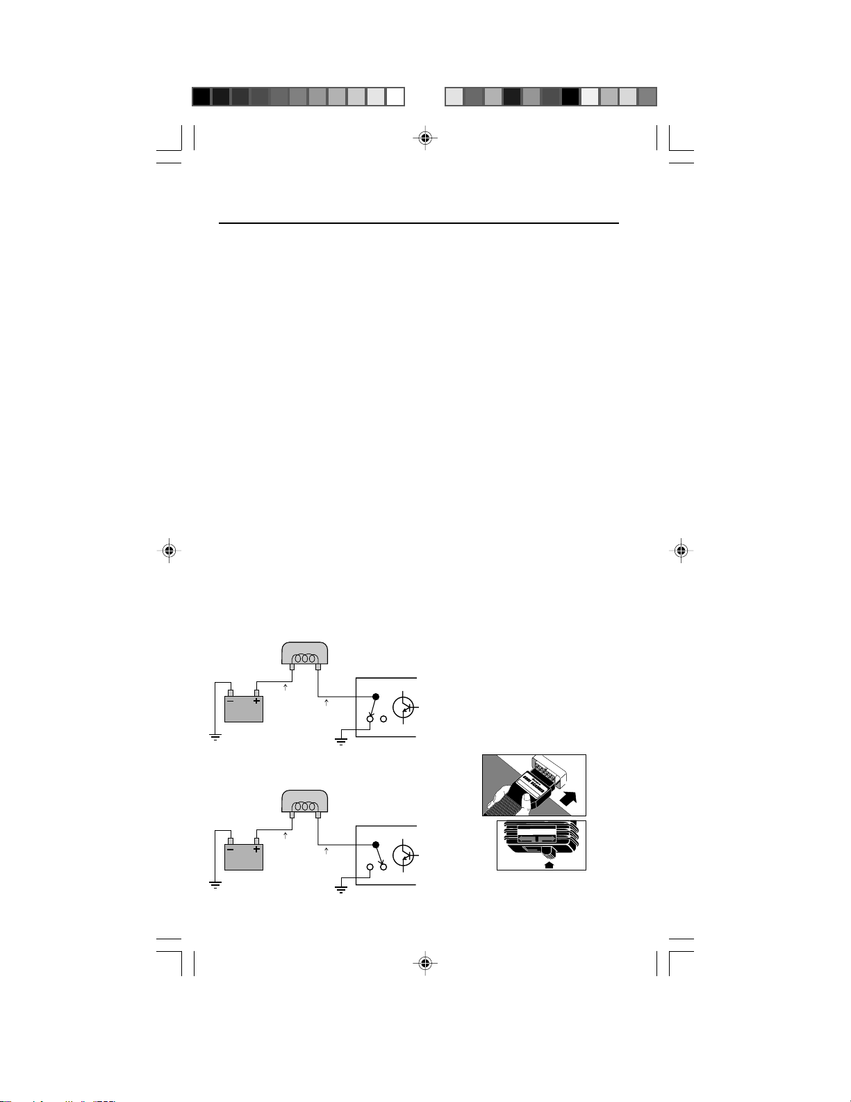
Relay and Solenoid
Circuit Test
Computer controlled relay and solenoid
coils are commonly wired as follows:
• One side of the coil is connected to
a source of vehicle battery power.
• The other side of the coil is wired to
the computer.
Inside the computer housing is a
transistor switch (often called a
RELAY COIL
12 volts
or more
RELAY ON
RELAY COIL
Less than
1.5 volts
COMPUTER
Transistor ON*
*Transistor action is
shown using a “switch”
representation for
clarity.
“driver”). The computer energizes the
coil by using the transistor switch.
Transistor ON:
– Transistor electrically connects end
of coil to circuit ground.
– Coil is ON because circuit is
complete. (Coil connected to battery
power and ground.)
Transistor OFF:
– Transistor disconnects end of coil
from circuit ground.
– Coil is OFF because circuit is open.
(Coil not connected to circuit
ground.)
Y ou can switch on most of the
computer controlled relay and solenoid
circuits except the fuel pump relay and
fuel injectors. This is helpful for
checking relay operation or making
wiring voltage checks. Do the following:
1) Safety First!
• Set the parking brake.
• Put shift lever in PARK (automatic
transmission) or NEUTRAL
(manual transmission).
• Block the drive wheels.
• Make sure ignition key is in OFF
position.
2) Plug the Code Scanner
into the Test Connector .
Put TEST switch on
ENGINE.
C
a
r
C
o
GM 1982 & higher - CP 9001
m
p
u
t
e
r
C
o
d
e
R
T
e
M
a
d
e
r
12 volts
or more
12 volts
or more
RELAY OFF
COMPUTER
Transistor OFF*
24
TEST
ABS
ENGINE
Page 25
3) Turn Ignition Key to ON Position
TEST
ABS
ENGINE
T
M
GM 1982 & higher - CP 9001
C
a
r
C
o
m
p
u
t
e
r
C
o
d
e
R
e
a
d
e
r
but DO NOT START THE ENGINE.
•
WARNING: Stay away from the
radiator cooling fan! It may turn on.
• Ignore the flashing Check Engine
light.
4) Computer Controlled Relays and
Solenoids are Turned ON
Exception:
Fuel pump and fuel
injectors are OFF. (Refer to vehicle
service manual for any other
exceptions.)
• Make any relay or
solenoid circuit
checks at this
time. Note the
following special
circuit actions...
– Fuel Injected
10
V
h
O
M
Autom
Dwell/Tach
2
M
2
m
ig
D
o
eg
M
2
0
2
2
0
M
0
0
2
K
s
odel CP 7676
ita
m
h
0
0
K
0
2
otive Volt/O
r
e
z
ly
a
n
A
e
in
g
n
l E
M
P
R
V
0
1
OFF
X
4
0
5
7
L
Y
C
5
L
Y
C
6
L
Y
C
8
L
Y
C
4
L
Y
C
5
L
Y
C
6
L
Y
C
ll
e
w
D
8
L
Y
C
K
2
0
0
2
hm
Engines Only:
The Idle Air
Control (IAC)
motor fully extends (most vehicles)
or moves back and forth.
– Carbureted Engines Only:
The
Idle Speed Control (ISC) motor, if
used on vehicle, moves back and
forth. Also, the Exhaust Gas
Recirculation (EGR) solenoid is
energized for 25 seconds.
5) Turn Ignition Key OFF.
• Remove Code Scanner and reinstall connector cover, if supplied.
• The computer system is now back
to normal.
• This completes the Relay and
Solenoid Circuit Test.
Field Service Test Fuel
Injected Engines Only
This is a quick check of the fuel control
system to verify proper operation especially after repair work. Service
manuals call this the “Field Service
Mode”. Do the following:
1) Safety First!
• Set the parking brake.
• Put shift lever in PARK (automatic
transmission) or NEUTRAL
(manual transmission).
• Block the drive wheels.
• Make sure ignition key is in OFF
position.
2) Test the “Check Engine” Light
(Also called
“Service Engine
Soon”, “Service
Engine Now” or
labeled with a small engine picture.)
• Turn ignition key from OFF to ON
position, but do not start the
engine.
• Verify that the light turns on.
• If the light does not turn on, you
have a problem with this circuit
which must be repaired before
proceeding. Refer to the “Diagnostic Circuit Check” procedure in your
vehicle service manual. (See
manual listings on page 4.)
3) Start the Engine
WARNING: Always operate vehicle
in well ventilated area. Exhaust
gases are very poisonous!
4) Plug the
Code
Scanner into
the Test
Connector.
Put TEST
switch on
ENGINE.
The engine
computer is now
in the “Field
25
Page 26
Diagnostic Mode.” The flashing
T
M
GM 1982 & higher - CP 9001
C
a
r
C
o
m
p
u
t
e
r
C
o
d
e
R
e
a
d
e
r
“Check Engine” light shows how the
fuel control system is operating.
See below.
Read Section 7, “Computer Basics”
or Section 8, “Glossary” for an
explanation of Open Loop and
Closed Loop operation.
IMPORTANT: The oxygen sensor
needs to be hot so the computer
can check the signal for proper fuel
delivery. Warm the engine by idling
for 2 minutes at 2000 RPM. Then,
gently rev the engine from idle to
part throttle several times. (This
creates a changing sensor signal
for the computer.) Finally, keep the
throttle steady, or at idle, for the rest
of the test.
Light flashes
2 times a second
The computer is in
Open Loop
operation. The
computer will run
“open loop” if it does
not see an oxygen sensor signal
because...
– The oxygen sensor is not hot
enough to operate (normal
condition if engine too cold or
sensor cooled down during idle)
or,
– Open circuit problems exist (bad
sensor or wiring). Note that this
condition will generate a trouble
code.
•
Light mostly ON while flashing:
system is running “rich”.
•
Light mostly OFF while flashing:
system is running “lean”.
Various mechanical, electronic or
wiring problems can cause the
computer to sense a “rich” or “lean”
running engine. Usually these
conditions will generate a trouble code,
such as 44 (lean exhaust) or 45 (rich
exhaust). Follow vehicle service
manual troubleshooting charts to find
the cause. The Field Service Test lets
you check to see if the problem was
fixed. (Light flashing equally ON and
OFF once a second.)
Note: While in the “Field Service
Mode”...
– New trouble codes are not stored
in computer memory.
– On some engines, the computer
will send a signal for a fixed spark
advance.
5) Turn Ignition Key OFF
• Remove
Code
Scanner
and reinstall
connector
cover, if
supplied.
• The
computer
system is
now back
to normal.
• This completes the Field Service
Test.
Light flashes
once a second
The computer is in
Closed Loop
operation. The
oxygen sensor is
sending a signal.
•
Light equally ON and OFF while
flashing:
system is running
correctly (proper air/fuel mixture).
26
Page 27

COMPUTER BASICS
What does the Engine Control Computer do?
This section further explains the engine
computer control system, the types of
sensors and how the computer controls
fuel delivery, idle speed and timing.
The following is an introduction to
computer controlled engine systems.
Additional information may be found in
books dealing with this subject
available at your local library or auto
parts store. The more you know about
the computer system, the better and
faster you can troubleshoot and fix
problems.
Why Computers?
Computer controls were installed in
vehicles to meet Federal Government
regulations for lower emissions and
better fuel economy. This all began in
the early 1980’s when purely mechanical control systems just were not good
enough anymore. A computer could be
programmed to precisely control the
engine under various operating
conditions and eliminate some
mechanical parts making the engine
more reliable.
Note that vehicle service manuals refer
to the computer as either the ECM
(Engine Control Module) or PCM
(Powertrain Control Module).
What the computer controls
The main control areas of the computer
are:
• Fuel delivery
• Idle speed
• Spark advance timing
• Emission devices (EGR valve,
carbon cannister, etc.)
The changes made to the basic engine
to allow a computer to control these
tasks are the only differences between
an older engine and a computerized
one. A little later we will discuss just
how the computer handles these tasks.
What has NOT changed?
A computer controlled engine is
basically the same as earlier types. It is
still an internal combustion engine with
pistons, spark plugs, valves and cams.
The ignition, charging, starting, and
exhaust systems are almost the same,
as well. Y ou test and repair these
systems the same way as before,
using familiar tools. The instruction
manuals for these tools show you how
to perform the tests. Y our compression
gauge, vacuum pump, dwell-tach
meter, engine analyzer, timing light,
etc., are still valuable!
The Engine Computer Control
System
The computer module is the “heart” of
the system. It is sealed in a metal box
and linked to the rest of the system by
a wiring harness. The computer
module is located in the passenger
compartment, usually behind the
dashboard or front kick panels. This
protects the electronics from moisture,
extreme temperatures and excess
vibration, which are common in the
engine compartment.
The computer is permanently
programmed by factory engineers. The
program is a complex list of instructions telling the computer how to
control the engine under various
driving conditions. To do its job, the
computer needs to know what is
happening and then it needs devices to
control things.
Sensors give the computer
information
The computer can only work with
electrical signals The job of the sensor
is to take something the computer
needs to know, such as engine
temperature, and convert it to an
electrical signal which the computer
27
Page 28
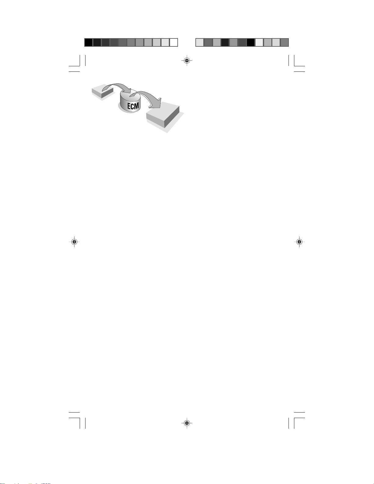
INPUT
SENSORS
BRAINS OF THE
COMPUTER
OUTPUT
ACTUATORS
can understand.
You can think of sensors as “high tech”
senders the devices found in older
vehicles for gauges and dashboard
message lights (oil pressure, fuel level,
etc.) Signals running into the computer
are referred to as “inputs.”
Sensors monitor such things as:
• Engine temperature
• Intake manifold vacuum
• Throttle position
• RPM
• Incoming air (temperature, amount)
• Exhaust gas oxygen content
Most engine computer systems will use
the sensor types listed above.
Additional sensors may be used
depending upon the engine, vehicle
type or other tasks the computer must
do. Note that information from one
sensor may be used by the computer
for many different tasks. For example,
engine temperature is something the
computer needs to know when
controlling fuel delivery, spark timing,
idle speed and emission systems. The
sensor information may be very
important for one engine control
function, but only used to “fine tune” a
second one.
There are several types of sensors
•
Thermistor
whose resistance changes with
temperature. It is used to measure
temperatures of coolant or incoming
air. It has two wires connected to it.
•
Potentiometer
position, such as throttle position or
EGR valve position. It connects to
three wires: one for power, one for
ground and one to carry the position
signal back to the computer.
•
Switches
– This is a resistor
– This signals a
– These are either ON
(voltage signal to the computer) or
OFF (no voltage signal to the
computer). Switches connect to two
wires and tell the computer simple
things, such as whether or not the
air conditioner is running.
•
Signal Generator
– These create
their own signal to tell the computer
of some condition, such as exhaust
gas oxygen content, camshaft
position, or intake manifold vacuum.
They may have one, two or three
wires connected to them.
The computer controls things with
actuators
The computer can only send out
electrical signals (referred to as
“outputs”). Devices called actuators
are powered by the computer to
control things. Actuator types include:
•
Solenoids
– These are used to
control a vacuum signal, bleed air,
control fuel flow, etc.
•
Relays
– These switch high
amperage power devices on and off,
such as electric fuel pumps or
electric cooling fans.
•
Motors
– Small motors are often
used to control idle speed.
Other output signals
Not all of the computer outgoing
signals go to actuators. Sometimes
information is sent to electronic
modules, such as ignition or trip
computer.
How the computer controls fuel
delivery
Good performance and low emissions
depend upon precise fuel control.
Early computer controlled vehicles
used electronically adjustable
carburetors, but fuel injectors were
soon introduced.
The job of the computer is to provide
the optimum mixture of air and fuel
(air/fuel ratio) to the engine for best
performance under all operating
conditions.
28
Page 29

The computer needs to know:
• ...what the engine operating
condition is.
Sensors used:
throttle position, manifold absolute
pressure, mass air flow, RPM.
• ...how much air is coming into the
engine.
Sensors used:
combination of manifold absolute
pressure, manifold air temperature,
RPM.
• ...how much fuel is being delivered.
The computer knows this by how
long it turns on the fuel injectors.
(The computer uses a “feedback
control” or “duty cycle” solenoid on
electronic controlled carburetors.)
• ...that everything is working the way
it should.
Sensor used:
sensor.
Note: Not all engines use every sensor
listed above.
coolant temperature,
mass air flow or a
exhaust gas oxygen
Cold engine warm-up condition
An example of “Open Loop” operation...
The coolant temperature sensor tells
the computer how warm the engine is.
Factory engineers know what the best
air/fuel mixture is for the engine at
various operating temperatures. (More
fuel is needed for a cold engine.) This
information is permanently programmed into the computer. After the
computer knows the engine temperature, it determines the amount of air
coming in, then it will look at its
programming to find out how much fuel
to deliver and operate the fuel injectors
accordingly. (Engines with electronic
carburetors don’t do any of this. They
have a thermostatically controlled
choke just like non-computer engines.)
This process is an example of “Open
Loop” operation by the computer. The
control system performs an action
(expecting a certain result), but has no
way of verifying if the desired results
were achieved. In this case, the
computer operates a fuel injector
expecting a certain amount of fuel to
be delivered. (The computer assumes
everything in the fuel system is
operating as expected.) In open loop
operation, the computer has no way of
checking the actual amount of fuel
delivered. Thus, a faulty fuel injector or
incorrect fuel pressure can change the
amount of fuel delivered and the
computer would not know it.
The computer system is forced to
operate “open loop” because no
sensor type is available which can
measure air/fuel ratios when the
engine is cold.
Hot engine cruise condition
An example of “Closed Loop”
operation...
The computer watches the coolant
temperature and throttle position
sensors to tell when the engine is all
warmed up and cruising. As before,
the computer determines the amount
of air coming into the engine, then
delivers the amount of fuel that should
provide the optimum air/fuel mixture.
The big difference is that this time the
computer uses the oxygen sensor to
check how well its doing and re-adjust
things, if needed, to make sure the fuel
delivery is correct. For example: If the
oxygen sensor indicates a “rich”
condition, the computer will compensate by reducing fuel delivery until the
oxygen sensor signals an optimum air/
fuel ratio. Likewise, the computer will
compensate for a “lean” condition by
adding fuel until the oxygen sensor
once again signals an optimum air/fuel
mixture.
This is an example of “Closed Loop”
operation. The control system
performs an action (expecting a
certain result), then checks the results
and corrects its actions (if necessary)
until the desired results are achieved.
The oxygen sensor only works when it
is very hot. During cold engine warmup, and sometimes at idle, the sensor
will be too cool to operate (no signal
sent). The computer must operate
"open loop" during this time because it
cannot use the sensor to check the air/
fuel ratio.
29
Page 30

Acceleration, deceleration and idle
conditions
As long as the engine and oxygen
sensor are hot, the computer can
operate “closed loop” for best economy
and least emissions. During the drive
conditions listed on the left, the
computer may have to ignore the sensor
and run “open loop,” relying on internal
programming for fuel delivery instructions. During idle, for example, the
oxygen sensor may cool down and stop
sending a signal. A different situation
can occur during wide-open-throttle
acceleration. The computer sometimes
adds additional fuel (on purpose) for
temporary acceleration power. The
computer knows it is running “rich” so it
ignores the sensor signal until the wideopen-throttle condition is over.
How the computer controls idle
speed
Throttle position and RPM sensors tell
the computer when the vehicle is
idling. (Sometimes an idle position
switch on the throttle is used.) The
computer simply watches RPM and
adjusts an idle speed control device
on the vehicle to maintain the desired
idle condition. Note that this is another
example of “closed loop” operation.
The computer performs an action
(activating an idle control device),
then watches the results of its action
(engine RPM) and readjusts as
necessary until the desired idle speed
is achieved.
There are two types of idle speed
control devices. The first is an
adjustable throttle stop that is
positioned by a computer controlled
motor. The second method lets the
throttle close completely. An air
passage bypassing the throttle allows
the engine to idle. A computer
controlled motor adjusts air flow
through the bypass to set idle speed.
Smaller engines can stumble or stall
at idle when the air conditioner
compressor turns on or the power
steering is used. To prevent this,
switches tell the computer when these
demands are coming so it can
increase the idle accordingly.
How the computer controls spark
advance timing
You set spark timing in a non-computer
engine by using a timing light and
adjusting the distributor at idle RPM.
During vehicle operation, timing is
changed by either engine vacuum
(vacuum advance function) or by engine
RPM (centrifugal advance function.)
These spark timing changes are done
mechanically inside the distributor.
Computer controlled vehicles using a
distributor still have you set spark timing
by using a timing light and adjusting the
distributor at idle RPM. The timing
changes which occur during vehicle
operation, however, are controlled
electronically. The computer looks at
sensors to determine vehicle speed,
engine load and temperature. (RPM,
throttle position, coolant temperature
and manifold pressure or mass air flow
sensors are used.) Then, the computer
adjusts timing according to factory
programmed instructions. Some
vehicles have a “knock” sensor. The
computer can “fine tune” the spark
timing if this sensor signals an engine
knock condition. A timing signal (“EST” Electronic Spark Timing) is sent by the
computer to an ignition module which
eventually creates the spark. The
computer uses a crankshaft position
sensor to determine piston position, so
it can send the spark timing (EST)
signal at the proper moment.
Newer ignition systems use no
distributor. There are several versions,
such as Computer Controlled Coil
Ignition (C3I), Direct Ignition System
(DIS), Integrated Direct Ignition (IDI)
and Opti-Spark. These systems use
multiple ignition coils. (2 spark plugs
are wired to each coil.) Sensors for
crankshaft position or camshaft
position (or both) are used by both the
ignition module and computer to fire
the correct coil at the proper time. The
computer provides spark advance
timing as before - by looking at vehicle
speed, engine load and temperature.
(RPM, throttle position, coolant
temperature and manifold pressure or
mass air flow sensors are used.) Refer
to vehicle service manual for detailed
ignition system descriptions.
30
Page 31

Computer controlled
emission systems
EGR (Exhaust Gas Recirculation)
Valve
The EGR valve lets exhaust gases reenter the intake manifold and mix with
the incoming air/fuel. The presence of
exhaust gases reduces combustion
temperatures in the cylinders and this
reduces poisonous NOx emissions.
The computer controls the flow of
gases through the EGR valve. The
EGR system is only used during warm
engine cruise conditions. A partially
open EGR valve at other times can
cause stalling. Various types of EGR
systems are used on different vehicles.
The EGR valve may be operated by
engine vacuum or with a computer
controlled electrical (or vacuum)
signal. See “EGR” in Glossary (Section
8) for more details.
Other computer
functions
The computer often controls various
other functions around the vehicle.
Detailed explanations may be found in
your vehicle service manual. Some
typical examples are...
Air Conditioner (A/C) Clutch
The computer can turn off the air
conditioner to reduce engine loading.
This is desirable during heavy
acceleration, engine cranking or low
speed steering maneuvering. The
computer may also disable the air
conditioner when refrigerant pressure
is too low (or high) to prevent A/C
damage. The computer stops the air
conditioner by using a relay to
disconnect voltage from the A/C
clutch.
Air Injection System
This system reduces harmful carbon
monoxide (CO) and hydrocarbon (HC)
emissions. The computer takes outside
air from an air pump and directs it to
the exhaust manifold during engine
warm-up. (The extra air helps partially
burned exhaust gases to completely
burn and reduce pollution.) After
warm-up, depending upon vehicle, the
air pump may send air down to the
catalytic convertor or “dump” it back to
the atmosphere. Various types of Air
Injection systems are used on different
vehicles. Refer to “Air Injection
System” in Glossary (Section 8) for
more explanation.
Fuel Evaporation Recovery
System
A special canister collects vapors
evaporating from the fuel tank,
preventing them from escaping into the
atmosphere and causing pollution.
During warm engine cruise conditions,
the computer opens a connection
between the cannister and the engine
(by energizing the Purge solenoid.)
Then, engine vacuum draws the trapped
fuel vapors into the engine for burning.
Radiator Cooling Fan
The computer controls engine cooling
fan (electric type) operation on most
vehicles. Usually the fan is turned on
when engine temperature exceeds a
certain level or when the air conditioning system is used. The computer uses
a relay to power the fan. Some
vehicles have a second fan for extra
cooling.
Variable Assist Power Steering
Saturn Vehicles: This system delivers
power steering assist based on vehicle
speed - little assist during high speed
straight steering, increased assist for
low speed turns. The computer
controls fluid flow in the power steering
pump using an Electronic Variable
Orifice (EVO) actuator (more fluid flow
provides more steering assist). Refer
to “EVO” in Glossary (Section 8) for
more details.
Torque Convertor Clutch
The computer can control the lock-up
clutch in an automatic transmission
torque convertor. The clutch is locked
during steady, warm engine cruise
31
Page 32

conditions. This improves fuel
economy by eliminating power loss in
the torque convertor. The computer
energizes a solenoid to achieve lockup. Signals from the engine coolant
temperature, throttle position and
vehicle speed sensors are used.
Transmission Control
Some transmissions have computer
controlled shifting. Two solenoids
mounted in the transmission are
energized singly, or in combination, to
select a gear ratio. The solenoids
direct the flow of fluid within the
transmission to cause the shift. The
computer uses throttle position,
vehicle speed, engine loading and
other sensor information to determine
the optimum shift performance. The
computer can also set the shift quality
- anywhere from harsh to smooth. This
is done using a “force motor” actuator
in the transmission to adjust the
internal fluid line pressure.
More information
The Glossary (Section 8) describes
various sensors and actuators used in
computer controlled engine systems.
You can learn more by reading these
definitions.
32
Page 33

GLOSSARY
A/C
Air conditioner.
A/C Clutch
relay
The ECM uses this relay to
energize the A/C clutch - to
turn the A/C system on or
off.
A/C On (A/C
Signal)
An input signal to the ECM
indicating that either the A/
C compressor is running or
that A/C operation is being
requested (depends upon
vehicle). Then ECM
adjusts idle speed to
prevent engine stalling
when the A/C system is
engaged. The ECM may
also turn on the engine
cooling fan.
A/C Pressure
sensor
This sensor is connected
to the A/C refrigerant line.
It measures refrigerant
pressure and sends a
voltage signal to the ECM.
The ECM will turn off the
A/C system (by deenergizing the A/C Clutch
relay) to prevent
compressor damage if the
pressure is too high or low.
A/C Pressure
switch
This is a mechanical switch
connected to the A/C
refrigerant line. The switch is
activated (which sends a
signal to the ECM) when the
A/C refrigerant pressure
becomes too low. The ECM
will turn off the A/C system
(by de-energizing the A/C
Clutch relay) to prevent
compressor damage. Some
vehicles have a second
switch activated when the
refrigerant pressure is too
high.
Actuator
Devices which are
powered by the ECM to
control things. Actuator
types include relays,
solenoids and motors.
Actuators allow the ECM to
control engine operation.
A/F
Air/fuel.
Air Injection
Reaction (AIR)
system
This is an emission control
system operated by the
ECM. During cold engine
warm-up, an air pump
injects outside air into the
exhaust manifold to help
burn hot exhaust gases.
This reduces pollution and
speeds warm-up of oxygen
sensor and catalytic
convertor. After the engine
is warm, the air will either
be “dumped” back to the
atmosphere (or into the air
cleaner) or sent into the
catalytic convertor. There
are various versions of the
AIR system - depends
upon vehicle.
The air pump is usually belt
driven by the vehicle
engine. The ECM controls
air flow from the pump by
operating two electrically
powered solenoid valves.
An Electric Air Divert Valve
either “dumps” the air to
atmosphere (valve
unpowered) or sends the
air further into the system
(valve energized). A
second control valve, the
Air Switching Valve, routs
the air to the catalytic
convertor (valve
unpowered) or to the
exhaust manifold (valve
energized). These two
valves may be individual
components or combined
into one assembly.
The ECM normally sends
air to the catalytic
convertor during warm
engine operation. The ECM
will divert air away from the
convertor to prevent
overheating damage under
certain operating
conditions, such as decel,
high RPM or “rich” air/fuel
conditions.
33
Some vehicles have an
electrically powered air
pump controlled by the
ECM. This system injects
air into the exhaust
manifold only when the
pump is energized and
running. No air is injected
when the pump is off. (The
air pump does not send air
to the catalytic convertor in
this version.)
ALDL
Assembly Line Diagnostic
Link. This is the connector
that the Code Scanner
plugs into for testing
purposes. The connector is
wired to the ECM, and is
usually located under the
dashboard on the driver’s
side.
BARO
Barometric Pressure
Sensor. (See MAP sensor
for explanation.)
Boost control
solenoid
Used on certain
supercharger equipped
engines. This solenoid is
normally energized by the
ECM. (This allows the
supercharger system to
operate normally.) The
ECM de-energizes the
solenoid during higher
engine speed and load
conditions to reduce boost
pressure.
Brake switch
signal
An input signal to the ECM
indicating that the brake
pedal is being depressed.
Vehicles with Cruise
Control systems monitor
the brake switch to
determine when to engage
(or disengage) the cruise
control function. The brake
switch may also have a
circuit supplying power to
the Torque Convertor
Clutch (TCC) solenoid.
This connection ensures
the TCC solenoid will
disengage when the brake
pedal is depressed (see
TCC definition).
Page 34

C3
Computer Command
Control. The name for the
GM electronic engine
control system used on
most vehicles built since
1982.
CALPAK
A “spare tire” for the ECM.
It is circuitry which can
operate the vehicle fuel
injectors in a limited
fashion should the ECM
malfunction. The CALPAK
is hidden behind an
access door on the ECM.
The replaceable CALPAK
module is only used on
certain ECM’s.
CAM
Camshaft Position Sensor.
This sensor sends a
frequency signal to the
ECM. Vehicles with
sequential fuel injection
(SFI) use this signal to
synchronize the injector
firing order. Some DIS
type ignition systems use
this signal to synchronize
spark plug firing.
Closed Loop (C/L)
This is when a control
system performs an action
(expecting a certain
result), then checks the
results and corrects its
actions (if necessary) until
the desired results are
achieved. Example: Fuel
delivery. The ECM
operates a fuel injector in
a way which should deliver
an optimum air/fuel
mixture - if everything in
the fuel system is
operating as expected! In
closed loop operation, the
ECM uses the oxygen
sensor to check the
results. (Fuel delivery may
be different than expected
because of variations in
fuel pressure or injector
operation.) If the oxygen
sensor indicates a “rich”
condition, the ECM will
compensate by reducing
fuel delivery until the
oxygen sensor signals an
optimum air/fuel ratio.
Likewise, the ECM will
compensate for a “lean”
condition by adding fuel
until the oxygen sensor
once again signals an
optimum air/fuel mixture.
Thus, closed loop operation
means the ECM can “fine
tune” control of a system to
get an exact result providing
the ECM has a sensor (or
other means) to check
results.
Continuity
An unbroken, continuous
circuit through which an
electric current can flow.
CPS
Crankshaft Position
Sensor. This sensor sends
a frequency signal to the
ECM. It is used to
reference fuel injector
operation and synchronize
spark plug firing on
distributorless ignition
systems (DIS).
CTS
Coolant Temperature
Sensor. This sensor is a
thermistor - a resistor
whose resistance
decreases with increases
in temperature. The sensor
is threaded into the engine
block and contacts the
engine coolant. The ECM
uses this signal for control
of fuel delivery, spark
advance and EGR flow.
Digital Signal
An electronic signal which
has only two (2) voltage
values: a “low” value (close
to zero) and a “high” value
(usually 5 volts or greater).
Sometimes the low voltage
condition is called “Off” and
the high voltage condition
is called “On”. Signals
which can have any
voltage value are called
“analog” signals.
DIS
Distributorless Ignition
System or Direct Ignition
System. A system which
produces the ignition spark
without the use of a
distributor.
Driver
A transistor “switch” inside
the ECM used to apply
power to an external
device. This allows the
ECM to control relays,
solenoids and small
motors.
34
Duty Cycle
A term applied to
frequency signals - those
which are constantly
switching between a small
voltage value (close to
zero) and a larger value
(usually 5 volts or greater).
Duty cycle is the
percentage of time the
signal has a large voltage
value. For example, if the
signal is “high” (large
voltage) half of the time
then the duty cycle is 50%.
If the signal is “high” only
one fourth of the time, then
the duty cycle is 25%. A
duty cycle of 0% means
the signal is always at a
“low” value and not
changing. A duty cycle of
100% means the signal is
always at a “high” value
and not changing. The
engine control computer
uses duty cycle type
signals when it wants more
than just “on-off” control of
an actuator. This is how it
works: A 50% duty cycle
signal going to a vacuum
switching solenoid means
the solenoid will be “on”
(passing full vacuum) half
the time and “off” (passing
no vacuum) half the time.
The average amount of
vacuum passing through
the solenoid will be one
half the full value because
the solenoid is only “on” for
one half the time. (The
signal switches at a rapid
rate, such as ten times a
second.) Thus, the
computer can get a
vacuum controlled actuator
to move half way between
“no vacuum” position and
“full vacuum” position.
Other positions can be
achieved by changing the
duty cycle of the control
signal which in turn
changes the average
amount of control vacuum.
DVM
Digital Volt Meter. An
instrument using a numeric
readout to display
measured voltage values
as opposed to a moving
needle on a gauge face.
Usually the instrument has
other measuring
capabilities, such as
resistance and current,
and may be called a DMM
Page 35

(Digital Multi-Meter). Most
DVM’s have 10 Megohm
input impedance. This
means the circuit under
test will not be
electronically disturbed
when the DVM is
connected for a measurement.
ECM
Electronic Control Module.
The “brains” of the engine
control system. It is a
computer housed in a
metal box with a number of
sensors and actuators
connected with a wiring
harness. Its job is to
control fuel delivery, idle
speed, spark advance
timing and emission
systems. The ECM
receives information from
sensors, then energizes
various actuators to control
the engine. The ECM is
sometimes called PCM
(Powertrain Control
Module) in vehicles having
other computers. These
other computers are used
for climate control,
entertainment systems,
etc.
EFI
Electronic Fuel Injection. A
term applied to any system
where a computer controls
fuel delivery to an engine
by using fuel injectors.
EGR
Exhaust Gas Recirculation.
The EGR system
recirculates exhaust gases
back into the intake
manifold to reduce NO
emissions. The EGR valve
controls the flow of
exhaust gases back into
the intake manifold. Some
EGR valves are operated
with a vacuum signal while
others are electrically
controlled. The amount of
EGR valve opening
determines the flow
through the valve. EGR
recirculation is only used
during warm engine cruise
conditions. EGR flow at
other times can cause
stalling or no starts. There
are three types of EGR
systems controlled by the
ECM.
One system uses exhaust
x
backpressure to operate
the EGR valve. The ECM
does not control the EGR
valve in this case, but it
can switch off the valve
completely when desired.
(The ECM operates a
solenoid switch to cut off
the backpressure control
signal to the valve.)
The second system uses
an EGR valve entirely
controlled by the ECM.
This valve contains three
individual flow passages:
small flow, medium flow
and large flow. Each
passage has an electric
solenoid. (Passage closed
when solenoid off passage open when
solenoid energized.) The
ECM energizes one or
more solenoids in
combination to set up
different flow rates through
the valve as required.
The third system is also
directly controlled by the
ECM. This EGR valve is
vacuum operated (the
normally closed valve
opens as vacuum is
applied). The ECM applies
control vacuum to the EGR
valve using a solenoid
connected to a vacuum
source. The ECM uses a
duty cycle type signal to
vary the amount of vacuum
passing through the
solenoid. (See “Duty
Cycle” definition.)
EMI
Electromagnetic
Interference. Undesired
signals interfering with a
needed signal. For
example: static on a radio
brought about by lightning
flashes or closeness to
high voltage power lines.
ESC
Electronic Spark Control.
This is an ignition system
function which works on
vehicles having a knock
sensor mounted on the
engine block. The knock
sensor is wired to circuitry
in a separate module
(early version) or inside the
ECM (later version). If the
sensor detects engine
knock, the ESC function
alerts the ECM which will
immediately retard the
35
spark to eliminate the
knock condition.
EST
Electronic Spark Timing.
An ignition system where
the ECM controls the spark
advance timing. A signal
called EST goes from the
ECM to the ignition module
which fires the spark coil.
The ECM determines
optimum spark timing from
sensor information - engine
speed and RPM, throttle
position, coolant
temperature, engine load,
vehicle speed, Park/Neutral
switch position and knock
sensor condition.
EVO
Electronic Variable Orifice
actuator. This is a solenoid
mounted in the power
steering pump. It is used in
some variable assist power
steering systems. The
solenoid controls the
amount of fluid passed to
the steering gear.
Increasing fluid flow
generates more power
steering assist. The ECM
controls the solenoid by
using a duty cycle type
signal (see “duty cycle”
definition). The ECM uses
information from the
vehicle speed sensor
(VSS) and the handwheel
sensor (which sends a
signal related to the rate of
steering wheel turning).
During low speed turns, the
ECM increases the EVO
solenoid opening to provide
additional steering assist.
The ECM decreases
steering assist during
straight line driving by
reducing fluid flow through
the EVO solenoid.
EVRV
Electronic Vacuum
Regulator Valve. This
actuator is controlled by
the ECM and is used to
vary the amount of vacuum
applied to a vacuum
operated device - usually
the EGR valve.
FBC
Feedback Carburetor. This
is used on early versions of
computer controlled
engines. It is a carburetor
which can have its fuel
Page 36

delivery modified by an
electronic signal from the
ECM. The signal controls a
“mixture control solenoid”
(MCS) attached to the
carburetor body.
Frequency
The frequency of an
electronic signal is a
measure of how often the
signal repeats a voltage
pattern in a one second
time span. For example:
suppose a signal starts at
zero volts, goes to five
volts then returns to zero
again. If this pattern
repeats itself 100 times in
one second, then the
signal frequency is 100
cycles per second - or 100
Hertz.
Fuel Injector
An electronically controlled
flow valve. Fuel injectors
are connected to a
pressurized fuel supply.
(The pressure is created by
a fuel pump.) No flow
occurs when the injector is
off (not energized). When
the injector is powered, it
opens fully allowing the fuel
to flow. The ECM controls
fuel delivery by varying the
amount of time the injectors
are turned on.
Fuel Pump
Relay
The ECM energizes this
relay to apply power to the
vehicle fuel pump. For
safety reasons, the ECM
removes power from the
fuel pump when ignition
signals are not present.
Fuel Pump
signal
This is a wire between the
ECM and the fuel pump
motor power terminal. The
ECM uses this signal to
verify when voltage is at
the fuel pump (for
diagnosing fuel pump
problems).
Gear switches
These are switches (usually
two) located inside certain
automatic transmissions.
The ECM monitors the
switches to determine what
transmission gear is
engaged. The switches are
activated by hydraulic
pressure and may be
normally open or closed,
depending upon vehicle.
The ECM uses gear
information for control of the
torque convertor clutch,
some emission systems and
for transmission diagnostic
purposes.
Ground
The return path for current
to flow back to its source.
(Usually the negative
battery terminal.) It is also
the reference point from
which voltage measurements are made. That is, it
is the connection place for
the minus (-) test lead from
the voltmeter.
Hall Effect
sensor
This sensor is a three wire
type containing electronic
circuitry. Two wires supply
power and ground. The
third wire carries the
sensor signal back to the
ECM. The sensor consists
of a permanent magnet
and a small module
containing a transistorized
Hall Effect switch. A small
air gap separates the
sensor and the magnet.
The magnetic field causes
the Hall switch to turn on
and send out a low voltage
signal. If a metal strip (iron
or steel) is placed in the
gap, it will block the
magnetic field from
reaching the Hall device.
This causes the Hall switch
to turn off and send a high
voltage signal out on the
signal wire.
The metal strips (blades)
are part of a cup or disk
attached to a rotating
component such as the
crankshaft or camshaft. As
the blades pass through
the sensor gap. the signal
voltage will switch high and
low creating a series of
pulses. The ECM
determines the speed of
rotation by measuring how
fast pulses appear. Hall
Effect type sensors may be
used to measure speed
and position of the
crankshaft or camshaft for spark timing or fuel
injector control.
36
Handwheel
sensor
This is a three wire sensor
(power, ground and signal
wires). It is used in some
Variable Assist Power
Steering systems. The
ECM uses the sensor
signal to determine how
fast the steering wheel is
being turned. Then the
ECM can apply the correct
amount of power steering
assist based on vehicle
speed. See “EVO”
(Electronic Variable
Orifice) actuator definition
for more information.
HEI
High Energy Ignition.
Ignition system which
pulses the spark coil by
using transistor switches
instead of mechanical
breaker points. The
electronics are in a module
which use a reference
signal coming from a
magnetic pick-up coil
driven by the camshaft.
Hertz (Hz)
A term for frequency cycles per second.
IAC
Idle Air Control. This is a
device mounted on the
throttle body. It adjusts the
amount of air bypassing a
closed throttle so that the
ECM can control idle
speed. The IAC is a
stepper motor which
moves a pintle within the
air bypass passage. When
the ECM wants to change
idle speed, it will move the
pintle backwards, for more
air and faster idle, or it will
move it forward for less air
and slower idle. (See
Stepper Motor definition.)
Idle switch
This is a switch built into
the tip of the ISC (Idle
Speed Control) motor
spindle. (See “ISC”
definition.) During idle, the
throttle rests against the
ISC spindle and activates
the switch. The ECM uses
this switch signal to
identify closed throttle
condition, then operates
the engine in an “idle” or
“deceleration” mode.
Page 37

Inputs
Electrical signals running
into the ECM. These
signals come from
sensors, switches or other
electronic modules. They
give the ECM information
about vehicle operation.
ISC
Idle Speed Control. This
refers to a small electric
motor mounted on the
throttle body and controlled
by the ECM. The ISC motor
moves a spindle back and
forth. When the throttle is
released during idle, it rests
on this spindle. The ECM
can control idle speed by
adjusting this spindle
position. The ECM
determines the desired idle
speed by looking at battery
voltage, coolant
temperature, engine load
and RPM.
Knock sensor
This sensor is used to
detect engine detonation
(knocking). When spark
knock occurs, the sensor
sends a pulsing signal.
Depending upon vehicle,
this signal goes either to the
ECM or a separate ESC
(Electronic Spark Control)
module. Then the spark
advance is retarded to
eliminate detonation. The
sensor contains a
piezoelectric element and is
threaded into the engine
block. Vibrating the element
generates the signal.
Special construction makes
the element only sensitive to
the engine vibrations
associated with knocking.
MAF
Mass Air Flow sensor. This
sensor measures the
amount of air entering the
engine and sends a
frequency or voltage signal
(depends upon sensor type)
to the ECM. The signal
voltage or frequency
increases when the amount
of incoming air goes up.
This gives the ECM
information required for
control of fuel delivery and
spark advance.
MAP
Manifold Absolute
Pressure sensor. This
sensor measures manifold
vacuum and sends a
frequency or voltage signal
(depends upon sensor
type) to the ECM. This
gives the ECM information
on engine load for control
of fuel delivery, spark
advance and EGR flow.
MAT
Manifold Air Temperature
sensor. This sensor is a
thermistor - a resistor
whose resistance
decreases with
temperature. It is threaded
into the intake manifold so
the ECM can determine
the temperature of the
incoming air. This is used
for fuel delivery
calculations.
MCS
Mixture Control Solenoid.
Used on computer
controlled vehicles having
carburetors. Built into the
carburetor, it allows the
ECM to “fine tune” fuel
delivery during warm
engine cruise.
MEMCAL
A small electronic
assembly containing the
the functions of both the
PROM and CALPAK. It is
hidden behind an access
door on the ECM and is
replaceable. Only some
ECM’s have MEMCAL.
MFI
Multi-Port Fuel Injection.
(See MPFI definition.)
Mode
A type of operating
condition, such as “idle
mode” or “cruise mode.”
MPFI
Multi-Port Fuel Injection. A
fuel injection system using
one injector for each
cylinder. The injectors are
mounted in the intake
manifold. The injectors are
fired in groups rather than
individually.
Open (circuit)
A break in the continuity of
a circuit such that no
current can flow.
37
Open Loop (O/L)
This is when the control
system performs an action
(expecting a certain result),
but has no way of verifying
if the desired results were
achieved. Example: the
ECM operates a fuel
injector expecting a certain
amount of fuel to be
delivered. (The ECM
assumes everything in the
fuel system is performing
as expected.) In open loop
operation, the ECM has no
way of checking the actual
amount of fuel delivered.
Thus, a faulty fuel injector
or incorrect fuel pressure
can change the amount of
fuel delivered and the ECM
would not know it.
In general, a control
system operates “open
loop” only when there is no
practical way to monitor the
results of an action.
Example: Fuel delivery
during cold engine warmup. The computer runs
“open loop”because the
oxygen sensor is not ready
to send a signal. Without
the sensor signal, the
computer can not check
the actual amount of fuel
delivered.
O
2
Oxygen sensor. The
oxygen sensor is threaded
into the exhaust manifold,
directly into the stream of
the exhaust gases. The
ECM uses the sensor to
“fine tune” fuel delivery.
The sensor generates a
voltage of 0.6 to 1.1 volts
when the exhaust gas is
rich (low oxygen content).
The voltage changes to 0.4
volts or less when the
exhaust gas is lean (high
oxygen content). The
sensor only operates after
it reaches a temperature of
349°C (660°F).
Outputs
Electrical signals sent from
the ECM. These signals
may activate relays or
other actuators for control
purposes around the
vehicle. The signals can
also send information from
the ECM to other electronic
modules, such as ignition
or trip computer.
Page 38

P/N
Park/Neutral switch. This
switch tells the ECM when
the gear shift lever is in the
Park or Neutral position.
Then the ECM will operate
the engine in an “idle”
mode.
Pressure Control solenoid
This solenoid is located
inside certain automatic
transmissions. The ECM
uses this solenoid to vary
the internal line pressure,
as required, based on
engine load condition
PROM
Programmable Read-Only
Memory. A small,
replaceable electrical
component hidden behind
an access door on the
ECM. The PROM contains
permanent programming
information the ECM needs
to operate a specific
vehicle model. Included
are vehicle weight, engine
and transmission type,
axle ratio and other
specifics.
PS
Power steering switch.
This tells the ECM when
power steering is being
used. The ECM can
prevent stalling on a small,
idling engine by watching
this switch and increasing
idle speed if power
steering is being used.
Purge solenoid
This device controls the
flow of fuel vapors from the
carbon canister to the
intake manifold. The
canister collects vapors
evaporating from the fuel
tank, preventing them from
escaping into the
atmosphere and causing
pollution. During warm
engine cruise conditions,
the ECM energizes the
Purge solenoid so the
trapped vapors are drawn
into the engine and
burned.
Quad Driver
An electrical device inside
the ECM. It functions as
four separate electronic
“switches” allowing the
ECM to energize relays or
solenoids.
Relay
A mechanical device for
switching high current
circuits on and off. It is
electronically controlled by
a low current circuit.
Relays allows a low power
ECM signal to control a
high power device such as
an electric cooling fan.
Reluctance
sensor
This sensor type consists
of a permanent magnet
with a coil of wire wrapped
around it. Nearby the
sensor is a toothed
“reluctor” ring made of iron
or steel. The ring is
attached around a rotating
component such as the
crankshaft. Whenever a
tooth from the ring passes
by the sensor, it attracts
the magnetic field lines
surrounding the magnet.
As the field lines move,
they pass through the wire
coil which generates a
small voltage pulse
(magnetic induction
principle). Thus, a voltage
pulse is generated every
time a tooth passes by the
sensor coil. The ECM
determines the speed of
rotation by measuring how
fast pulses appear.
Reluctance sensors may
be used for:
Crankshaft or Camshaft
speed, position (spark
timing or fuel injector
control).
Driveshaft
(transmission or torque
convertor control, cooling
fan use, variable assist
power steering and “cruise
control”).
Wheel Speed
brake or traction control
systems.
– vehicle speed
– anti-lock
–
Sensor
Device which give the ECM
information. The ECM can
only work with electrical
signals. The job of the
sensor is to take something
the ECM needs to know,
such as engine tempera-
38
ture, and convert it to an
electrical signal which the
ECM can understand. The
ECM uses sensors to
measure such things as
throttle position, coolant
temperature, engine speed,
incoming air and the like.
SFI or SEFI
Sequential Fuel Injection
or Sequential Electronic
Fuel Injection. A fuel
injection system using one
injector for each cylinder.
The injectors are mounted
in the intake manifold. The
injectors are fired
individually in the same
sequence as the spark
plug firing sequence.
Shift solenoid
Used in computer
controlled transmissions.
The solenoids (usually
two) are located in the
transmission housing and
are controlled by the ECM.
The ECM energizes the
solenoids individually, or in
combination, to select a
specific gear. (The
solenoids control the flow
of hydraulic fluid to the
transmission shifting
valves.) The ECM selects
the appropriate gear ratio
and shift point based upon
engine operating
conditions.
Short (circuit)
A fault condition: an
unwanted connection of
one electric circuit to
another causing a change
in the normal current flow
path.
Solenoid
A device to convert an
electrical signal to
mechanical motion. It
consists of a coil of wire
with a movable metal rod
in the center. When power
is applied to the coil, the
resulting electromagnetism
moves the rod and
performs some mechanical
action. The ECM often
uses solenoids to switch
vacuum lines on and off.
This allows the ECM to
control vacuum operated
devices such as an EGR
valve. Fuel injectors are
another type of solenoid.
Page 39

Stepper Motor
A special type of electric
motor with a shaft that
rotates in small “steps”
instead of a continuous
motion. A certain
sequence of frequency
type signals is required to
step the motor shaft. A
different signal sequence
will step the shaft in the
opposite direction. No
signals keeps the shaft still
in position. A constant
signal drive will
continuously rotate the
shaft. The shaft is usually
connected to a threaded
assembly which moves
back and forth to control
things such as idle speed
bypass air flow (see IAC).
The engine computer
sends the correct signals
to the motor for control.
TBI
Throttle Body Injection. A
fuel injection system
having one (or two)
injectors mounted in a
centrally located throttle
body, as opposed to
positioning the injectors
close to an intake valve
port.
TCC solenoid
Torque Convertor Clutch
solenoid. The ECM uses
this solenoid to control the
lock-up clutch in the
transmission torque
convertor. (When
activated, the lock-up
clutch directly connects the
engine to the
transmission.) During
warm engine cruise
conditions, the ECM
energizes this solenoid to
eliminate transmission
slippage and increase fuel
economy. The ECM
releases the lock-up action
when driving conditions
require the transmission to
operate as normal.
TDC
Top Dead Center. When a
piston is at its uppermost
position in the cylinder maximum compression.
Thermistor
A resistor whose
resistance changes with
temperature. Thermistors
are used as sensors for
vehicle coolant and
manifold air temperature.
The resistance decreases
as temperature goes up.
TPS
Throttle Position Sensor.
This is a rotary type
potentiometer connected
to the throttle shaft. It has
a voltage signal output
which increases as the the
throttle is opened. This
sensor is used by the ECM
for idle speed, spark
advance, fuel delivery,
emission system and
automatic transmission
(electronic type) control.
TTS
Transmission Temperature
sensor. This sensor is a
thermistor - a resistor
whose resistance
decreases as temperature
rises. It is mounted within
the transmission housing.
The ECM uses this sensor
to monitor transmission
operating temperature.
VSS
Vehicle Speed Sensor.
This sensor sends a
frequency signal to the
ECM. The frequency
increases as the vehicle
moves faster to give the
ECM vehicle speed
information.
WOT
Wide Open Throttle. The
vehicle operating condition
brought about when the
throttle is completely (or
nearly so) open. The ECM
will typically deliver extra
fuel to the engine at this
time for acceleration
purposes. The ECM uses
the Throttle Position
Sensor to identify the WOT
condition.
39
Page 40

ABS BASICS
A General Description of ABS Systems
The following is an overview of AntiLock Brake Systems (ABS). There are
several different types and versions.
Refer to vehicle service manual for
specific details.
IMPORTANT: To service ABS systems
safely and effectively , you must obtain
a service manual for your vehicle and
carefully follow all procedures.
What is ABS?
ABS is a safety feature designed to
minimize accidents during braking.
When engaged, ABS stops the vehicle
in the shortest distance possible while
giving the driver the greatest amount
of steering control.
Heavy braking on non-ABS vehicles
often causes wheels to lock up. This
leads to a wheel skid condition
resulting in loss of maneuverability and
a long stopping distance. The job of
ABS is to prevent wheel lock-up.
Front Wheel
Speed Sensors
Master Cylinder
The ABS System
An ABS system combines a conventional hydraulic braking system along
with additional components including:
– An ABS computer (separate from
the engine computer)
– Wheel speed sensors
– Hydraulic control unit
The computer module controls the
ABS system. This module is called
Electronic Brake Control Module
(EBCM), or similar. The computer
monitors wheel speed, acceleration
and deceleration using signals sent by
the wheel speed sensors. If the
computer determines wheel lock-up is
likely during braking, it will control
brake pressure using the Hydraulic
Control Modulator. ABS components
and braking operation will be detailed
later in this section. As a safety
feature, the system reverts to normal
hydraulic braking operation if the ABS
computer cannot operate.
Rear Wheel
Speed Sensors
Hydraulic
Control
Modulator
Electronic Brake
Control Unit
(ABS computer)
Courtesy of General Motors Corp.
Typical 4-Wheel Anti-Lock Brake System
40
Page 41

ABS Types
There are three basic types...
• RWAL (Rear Wheel Anti-Lock)
This is the simplest ABS system
(mostly used on small rear-wheel-drive
trucks). Only the rear wheels are ABS
controlled – not the front. This version
stops the vehicle in a straight line but
does not allow the driver to maneuver
because the front wheels may lock.
A single speed sensor (usually
mounted in the differential) monitors
driveshaft rotation. The ABS computer
examines changes in shaft speed to
predict rear wheel lock-up. Both rear
brakes are operated by a single
hydraulic channel. The ABS computer
controls rear hydraulic performance,
when necessary, using a single
channel Hydraulic Control Modulator
(described later).
• 3 Channel
This ABS system is a higher performance version of the RWAL version
just described. Used on rear wheel
drive vehicles, this system delivers
short stopping distance and maneuvering control during heavy braking. All
four wheels are ABS controlled.
Three hydraulic braking channels are
used: right front wheel, left front wheel
and a single channel for both rear
wheels. The ABS computer uses a
three channel Hydraulic Control
Modulator (described later) to operate
the individual brake circuits as
necessary.
The two rear wheels are monitored with
a single speed sensor (usually
mounted in the differential). This is
similar to the RWAL system described
before. Two more speed sensors
individually monitor each of the front
two wheels.
• 4WAL (4 Wheel Anti-Lock) also
called “4 Channel”
This ABS system is similar to the 3
channel version previously described,
but is designed for front wheel drive
vehicles. The main difference is that
four speed sensors are used, instead
of three, to individually monitor all four
wheels. The hydraulic portion is the
same as the 3 Channel system. The
ABS computer uses a three channel
Hydraulic Control Modulator to control
the right front wheel, the left front
wheel and both rear wheels.
ABS Components
Electronic Brake Control Module
(EBCM)
May also be called Electronic Control
Unit (ECU), or similar.
This is a computer module - the
“brains” of the ABS system. The
module is located either in the
passenger compartment, or close to
the ABS hydraulic controller in the
engine area. The module monitors
wheel speed sensors to determine if
lock-up is about to occur when brakes
are applied. If so, the module will
operate the ABS hydraulic solenoids to
control brake pressure and prevent
lock-up. (This process is described
later. Refer to “How ABS Controls
Brakes.”) The EBCM also performs
checks of itself, and other ABS
components, during vehicle operation.
If problems are found, the ABS system
is disengaged, the dashboard warning
light is energized and a diagnostic
trouble code is stored in ABS computer
memory.
Brake Light Switch
This is the usual switch which
energizes the rear brake lights when
the brake pedal is applied. The ABS
computer is sometimes connected to
this switch - depends upon system.
(Note: The engine control computer
may also be connected to this switch.)
Some ABS systems are active
continuously. Other types wait for the
brake light switch to close before
operating.
Wheel Speed Sensor
This is a reluctance sensor (a 2-wire
type). It consists of a permanent
magnet with a coil of wire wrapped
around it. Nearby the sensor is a
toothed ring made of iron or steel
(sometimes called a reluctor, sensor
ring, exciter ring, pick-up ring or tone
41
Page 42

Wheel Speed Sensor Operation
To
computer
Magnet
Wire Coil
SN
{
Typical Front Sensor Typical Rear Sensor
Hub and rotor
assembly
Sensor
ring
wheel). The ring is attached to the
wheel, drive axle or transmission shaft.
Whenever a tooth from the ring passes
by the sensor, it attracts the magnetic
field lines surrounding the magnet. As
the field lines move, they pass through
the wire coil and generate a small
voltage pulse (magnetic induction
principle). Thus, a voltage pulse is
generated every time a tooth passes
by the sensor coil. This voltage signal
is sent to the ABS computer.
The ABS computer determines wheel
speed by measuring how fast pulses
appear. The faster the wheel spins, the
more quickly pulses will appear. Note:
The voltage pulses get larger as the
wheel speeds up. (The computer
ignores pulse size.) Values can range
from a fraction of a volt (low speed) to
several volts (high speed).
Hydraulic Control Modulator
This is an assembly containing
solenoid operated hydraulic valves. It
Wheel
speed
sensor
Hydraulic Control
Modulator
Teeth Sensor
Air
gap
Sensor
ring
(Typical)
This is why the solenoid assembly is
called a “modulator.”)
Some modulator types use two
solenoid valves per brake circuit: an
“isolation” valve and a “dump” valve.
Other types use a special “two-stage”
solenoid per brake circuit. This “two
stage” solenoid provides the same
brake fluid control as the “isolation”
and “dump” solenoids.
The “isolation” and “dump” solenoids
have two positions: coil off and coil
fully energized. The “two stage”
solenoid has an additional position:
coil off, coil
fully energized. ABS computers
controlling “two stage” type solenoids
have special built-in switching circuits
to energize the solenoid properly.
Refer to “How ABS Controls Brakes”
(later in this section) for a description
of how the modulator is used.
Accumulator and Electric Pump
These two components work together.
Depending upon system, their use (and
construction) will differ a great deal.
• Low Pressure type: Accumulator
and pump only used during ABS
operation.
– Accumulator acts as a reservoir. It
collects hydraulic fluid “bled” from
ring
Rotation
Axle
housing
Wheel
speed
sensor
is usually mounted
close to the master
cylinder. (Some
systems combine the
hydraulic control
modulator and the
master cylinder into
one complete unit.)
The valves are
connected in the brake
lines between the
master cylinder and
the wheel caliper (or
wheel cylinder). The
ABS computer controls
brake line pressure by
operating one, or
more, of these
solenoid valves. (In
ABS systems, the
process of varying
brake pressure is
called “modulation.”
partially
energized and coil
42
Page 43

brake circuit during ABS operation.
(ABS relieves brake line pressure to
avoid wheel lock-up.) Four wheel
ABS systems use two accumulators:
one for the rear wheel circuit and the
other for the front wheel circuit.
The accumulator contains a
moveable diaphragm which
separates the inside into two
chambers. One chamber collects the
hydraulic fluid. The other side
contains a spring pressing against
the diaphragm. Because of the
spring, accumulator hydraulic
pressure is about 150 PSI.
– The electric pump operates to
remove fluid from the accumulators
and return it to the master cylinder.
– Some systems have no pump. The
spring driven diaphragm in the
accumulator pushes brake fluid back
into the master cylinder through a
compensation port.
• High Pressure type: Accumulator
and pump used for both ABS and
normal brake operation.
– Accumulator stores fluid under very
high pressure (up to 2600 PSI). The
accumulator contains a moveable
diaphragm which separates the
inside into two chambers. One
chamber holds the hydraulic fluid.
The other side is filled with high
pressure Nitrogen gas. The gas acts
as a very strong spring keeping the
hydraulic fluid under great pressure.
The pressurized fluid is used during
normal and ABS braking.
– The electric pump is a special high
pressure hydraulic type. It runs as
needed to maintain high hydraulic
pressure in the accumulator. The
pump is not controlled by the ABS
computer. A pressure activated switch
threaded into the accumulator fitting
turns the pump on and off as required.
Warning Light
All vehicles have a red “BRAKE” light
on the dashboard to warn of problems
in the normal braking system. Some
ABS systems use this “BRAKE” light to
warn of ABS problems as well. Other
vehicles have a separate amber
“ANTILOCK” dashboard light to warn of
ABS problems. The ABS computer
controls the warning light.
Relays
Various relays are used by ABS -
depends upon system. Refer to ABS
circuit schematics in vehicle service
manual. Typical relays include:
• ABS Power relay: Supplies power
to the electronic brake control module
(ABS computer). Note: This relay may
have built-in diodes to protect the
computer against voltage surges or
reverse voltage conditions.
• Electric Pump relay: Used by the
ABS computer to operate the electric
pump. (This is the pump associated
with the accumulator previously
described.)
• ABS Solenoid relay: Connects
vehicle battery voltage to the solenoid
circuits in the Hydraulic Control
Module. Note: This does not turn on
the solenoids. The ABS computer
controls individual solenoids by
completing each circuit as required.
Digital Ratio Adapter Controller
(DRAC)
This is a small electronic module used
on some rear wheel drive vehicles. It
works with the speed sensor mounted
in the differential. The DRAC receives
the sensor signal, processes it, then
sends it to the ABS computer,
speedometer and cruise control (if
installed). The DRAC is matched to a
specific rear axle ratio and tire size.
Any change to the rear axle ratio or
tire size requires recalibrating (or
replacing) the DRAC.
Lateral Acceleration Sensor
This sensor is only used on Corvette
ABS systems. It is a small module
used to monitor the amount of
sideways force exerted on the vehicle
during a hard turn. The module sends
a voltage signal to the ABS computer.
The computer uses this signal to
modify ABS control of the rear brakes.
How ABS Controls Brakes
Depending upon system, the ABS
computer will either:
43
Page 44

– continuously monitor wheel speed
or...
– wait for brake pedal application
before monitoring wheel speed.
The ABS computer controls braking
action when wheel speed acceleration
or deceleration indicates lock-up is
about to occur.
Four-Wheel Drive Vehicle Note: The
ABS computer will not allow ABS
braking during four-wheel drive
operation. (A switch in the four-wheel
drive powertrain sends a signal to the
ABS computer.)
The ABS computer controls brake line
pressure by operating one, or more,
solenoid valves in the Hydraulic
Control Modulator. Some systems use
two solenoid valves per brake circuit:
an “isolation” valve and a “dump” valve.
Other systems use a special “twostage” solenoid per brake circuit. Either
system controls brake line pressure in
the same way.
(Systems using two-stage solenoid:
Solenoid is not energized. Hydraulic
flow same as described above.)
ABS Braking – Pressure Maintain
Wheel speed signals indicate lock-up
is about to occur. ABS computer takes
first step in brake control cycle: isolate
wheel caliper/cylinder from master
cylinder – maintain fluid pressure to
wheel.
Isolation
Valve
CLOSED
Dump
Valve
CLOSED
(Master
Cylinder)
T o Wheel
Caliper or
Cylinder
(Accumulator
or Reservoir)
HYDRAULIC PRESSURE FLOW
Normal Braking (no ABS action)
ABS computer sees normal wheel
speed changes. No ABS action is
necessary.
From
Isolation
Valve
OPEN
Dump
Valve
CLOSED
Master
Cylinder
T o Wheel
Caliper or
Cylinder
(Accumulator
or Reservoir)
HYDRAULIC PRESSURE FLOW
–
Isolation valve is OPEN (not
energized).
Brake circuit operates
normally. Hydraulic pressure from
master cylinder passes through
isolation valve to wheel caliper/
cylinder.
–
Dump valve is CLOSED (not
energized)
. This valve has no effect
on the brake pressure when it is
closed.
–
Isolation valve is CLOSED
(energized).
Pressure flow between
master cylinder and brake caliper/
cylinder is blocked because of
closed valve. Existing pressure to
wheel is maintained because
hydraulic fluid is trapped between
isolation valve and wheel. Closed
isolation valve also prevents any
increases in master cylinder
pressure from reaching wheel
caliper/cylinder.
–
Dump valve is CLOSED (not
energized).
This valve has no effect
on the brake pressure when it is
closed.
(Systems using two-stage solenoid:
Solenoid is partially energized.
Hydraulic flow same as described
above.)
44
Page 45

ABS Braking – Pressure Decrease
Wheel speed signals indicate lock-up
is still about to occur. ABS computer
takes next step in brake control cycle:
decrease hydraulic pressure to wheel
caliper/cylinder.
ABS Braking – Pressure Increase
Wheel speed signals indicate absence
of lock-up condition. ABS computer
takes last step in brake control cycle:
increase hydraulic pressure to wheel
caliper/cylinder.
Isolation
Valve
CLOSED
Dump
Valve
OPEN
(Master
Cylinder)
From
Wheel
Caliper or
Cylinder
To
Accumulator
or Reservoir
HYDRAULIC PRESSURE FLOW
–
Isolation valve is CLOSED
(energized).
Pressure flow between
master cylinder and brake caliper/
cylinder remains blocked because of
closed valve. Closed isolation valve
still prevents changes in master
cylinder pressure from reaching
wheel caliper/cylinder.
–
Dump valve is OPEN (energized)
Hydraulic pressure to wheel caliper/
cylinder is reduced. The open dump
valve relieves pressure by “bleeding”
some fluid out of the wheel circuit.
The fluid travels either: back to the
brake reservoir or to an accumulator
- depends on system. Fluid
collected in the accumulator is
returned to the master cylinder.
Some systems use an electric pump
to move the fluid. Other systems
briefly pause the ABS brake cycle.
Then, the spring driven diaphragm
inside the accumulator pushes the
fluid back to the master cylinder.
(Systems using two-stage solenoid:
Solenoid is fully energized. Hydraulic
flow same as described above.)
Isolation
Valve
OPEN
Dump
Valve
CLOSED
HYDRAULIC PRESSURE FLOW
–
Isolation valve is OPEN (not
energized)
. Master cylinder is
reconnected to wheel caliper/cylinder.
Once again, hydraulic pressure from
master cylinder passes through
isolation valve to wheel.
–
Dump valve is CLOSED (not
.
the brake pressure when it is closed.
energized)
. This valve has no effect on
(Systems using two-stage solenoid:
Solenoid is not energized. Hydraulic
flow same as described above.)
The ABS system is capable of
repeating the brake cycle at a rapid
rate - up to 15 times a second.
Other ABS Uses
On some vehicles, the components of ABS
are shared with another system: Anti-Slip
Regulation (ASR) also known as traction
control. This system prevents wheel slip
during acceleration on slick road surfaces.
The ASR system is controlled by a
computer module. This ASR computer is
connected to the same wheel speed
sensors and hydraulic control modulator
used by ABS. If one drive wheel slips
excessively during acceleration, power
will be transferred to the other drive wheel
by applying brake pressure to the slipping
wheel. (The ASR computer may try to
stiffen throttle movement or retard engine
timing before applying brake action.)
45
From
Master
Cylinder
T o Wheel
Caliper or
Cylinder
(Accumulator
or Reservoir)
Page 46

ABS SAFETY
General Safety Guidelines to Follow
When Working on ABS Vehicles
WARNING: T o avoid personal injury , DO NOT open a bleeder
valve or loosen a hydraulic line while ABS is pressurized.
Always follow vehicle manufacturer’s procedures to depressurize ABS before servicing.
• Always use specially designed ABS brake hoses and fittings
when replacing these parts.
• Always use ABS recommended brake fluids. DO NOT use
silicone brake fluids in ABS systems.
• Always wear approved eye protection.
• Always operate the vehicle in a well ventilated area.
inhale exhaust gases - they are very poisonous!
• Always keep yourself, tools and test equipment away from all
moving or hot engine parts.
• Always make sure the vehicle is in park (Automatic transmission)
or neutral (manual transmission) and that the parking brake is
firmly set. Block the drive wheels.
• Never lay tools on vehicle battery. You may short the terminals
together causing harm.
• Never smoke or have open flames near vehicle. Vapors from
gasoline or charging battery are highly explosive.
• Never leave vehicle unattended while running tests.
• Always turn ignition key OFF when connecting or disconnecting
electrical components, unless otherwise instructed.
• Always follow vehicle manufacturer’s warnings, cautions and
service procedures.
Do not
CAUTION:
known as Supplemental Inflatable Restraint (SIR) system. Y ou
must
the air bag components or wiring. If the cautions are not followed,
the air bag may open up unexpectedly, resulting in personal injury.
Some vehicles are equipped with safety air bags, also
follow vehicle service manual cautions when working around
46
Page 47

ABS TIPS
Useful Hints to Know When
Troubleshooting ABS Systems
IMPORT ANT: Always follow vehicle service manual procedures for any ABS
repairs.
(Manual listings on page 4.)
• Do a thorough visual and “hands-on”
inspection first. You can often find the
cause of many problems by just
looking.
• ABS systems rely on accurate wheel
sensor signals. Anything which
interferes with the wheel sensor can
create intermittent problems or set
trouble codes. Note the following:
–Do not mix tire sizes. Rolling
diameter must be the same for all
four tires. Differently sized tires (or
using a “compact” spare) can cause
inaccurate wheel speed sensor
operation.
–Do not tap the speed sensor or
toothed sensor ring. Tapping these
parts can disturb their magnetic
properties and upset wheel speed
sensor operation. Press (do not
hammer) toothed sensor ring onto
hub, if service is required.
–Do not overtighten wheel lug nuts.
(Specifications are in vehicle
service manual.) Brake drum or
rotor may bend causing inaccurate
wheel speed sensor operation.
–Do not coat wheel speed sensor
parts with grease. Refer to vehicle
service manual for recommended
material.
–Check spacing between wheel
speed sensor and toothed ring,
especially after servicing. Incorrect
spacing can cause faulty sensor
operation. Specifications are in
vehicle service manual.
–Check for cracked or missing teeth
on the wheel speed sensor ring.
• Spinning tires (or axle) on a
stationary vehicle during a service
procedure may set ABS trouble
codes.
• Radio transmitters can interfere with
operation of ABS computer. Keep
antenna wiring from a CB radio or
portable telephone away from ABS
wiring
• Check ABS power circuits:
–Make sure vehicle alternator and
voltage regulator are working
properly.
–Make sure vehicle battery is fully
charged.
–Make sure all ABS fuses, fusible
links and relays are good
• Inspect wiring for:
–Contact
with sharp
edges.
(This
happens
often.)
–Contact
with hot surfaces, such as exhaust
manifolds.
–Pinched, burned or chafed
insulation.
–Proper routing and connections.
• Check electrical connectors for:
–Corrosion on pins.
–Bent or damaged pins.
–Contacts not properly seated in
housing.
–Bad wire crimps to terminals.
Problems with electrical
connectors are common.
Inspect carefully. Note that some
connectors use a special grease on
the contacts to prevent corrosion. Do
not wipe off! Obtain extra grease, if
47
Page 48

needed, from your vehicle dealer. It is
a special type for this purpose.
• Make sure any recommended
system flushing has been performed. Corrosion or dirt in ABS
valving can result in poor pedal
performance.
• Some body and chassis work
procedures can harm the ABS
computer:
– Disconnect vehicle computer
modules when using electric
welding equipment.
– Do not expose the ABS computer to
high heat for a long time (for
example, during vehicle painting).
Keeping temperature below 185°F
(85°C) for less than 2 hours is
usually safe.
48
Page 49

READING CODES
How to Use the Code Scanner to Read ABS Codes
1) Use the chart to find the ABS system used on your vehicle.
2) Refer to the page listed where you will find...
• preliminary checks you need to make before reading codes,
• the code reading procedure,
• the procedure for erasing codes from ABS computer memory,
• a list of code definitions.
1988
Model System Page
Blazer 7 84
C Series
Pickup Truck 7 84
K Series
Pickup Truck 7 84
Sierra 7 84
1989
Model System Page
98 Regency 5 74
Astro 7 84
Blazer 7 84
Bonneville 5 74
Bonneville SSE 5 74
C Series
Pickup Truck 7 84
Delta 88 5 74
DeVille 5 74
Eldorado 6 79
Electra 5 74
Fleetwood 5 74
Jimmy 7 84
K Series
Pickup Truck 7 84
Park Avenue 5 74
Reatta 6 79
Riviera 6 79
S Series (2WD)
Pickup Truck 7 84
Safari 7 84
Seville 6 79
Sierra 7 84
Toronado 6 79
49
Page 50

1990
Model System Page
98 Regency 5 74
Astro 7 or 8
Blazer 7 84
Bonneville 5 74
Bonneville SSE 5 74
Brougham 2 56
C Series
Pickup Truck 7 84
Corvette 1 51
Delta 88 5 74
DeVille 5 74
Eldorado 6 79
Electra 5 74
Fleetwood 5 74
G Series (RWD)
Van 7 84
Jimmy 7 84
K Series
Pickup Truck 7 84
Park Avenue 5 74
R Series Truck 7 84
Reatta 6 79
Riviera 6 79
S Series
Pickup Truck 7 84
Safari 7 or 8
Seville 6 79
Sierra 7 84
Suburban 7 84
T Series
Pickup Truck 7 84
Toronado 6 79
Trofeo 6 79
V Series Truck 7 84
See note p. 50
See note p. 50
1991
Model System Page
Astro 7 or 8
Blazer 7 or 8
Bravada 8 88
Brougham 3 62
C Series
Pickup Truck 7 84
Caprice 2 56
Corvette 1 51
Custom Cruiser 2 56
Eldorado 3 62
G Series (RWD)
Van 7 84
Jimmy 7 or 8
K Series
Pickup Truck 7 84
R Series Truck 7 84
Reatta 3 62
Riviera 3 62
Roadmaster 2 56
S Series
Pickup Truck 7 or 8
Safari 7 or 8
Seville 3 62
Sierra 7 84
Sonoma 8 88
Suburban 7 84
Syclone 8 88
T Series
Pickup Truck 7 or 8
Toronado 3 62
Trofeo 3 62
Typhoon 8 88
V Series Truck 7 84
See note p. 50
See note p. 50
See note p. 50
See note p. 50
See note p. 50
See note p. 50
50
Page 51

1992
Model System Page
Astro 7 or 8
Blazer 7 or 8
Bravada 8 88
Brougham 2 56
C Series
Pickup Truck 7 or 8
Eldorado 3 62
G Series (RWD)
Van 7 84
Jimmy 7 or 8
K Series
Pickup Truck 7 or 8
Riviera 3 62
S Series
Pickup Truck 7 or 8
Safari 7 or 8
Seville 3 62
Sierra 7 or 8
Sonoma 8 88
Suburban 7 or 8
Syclone 8 88
T Series
Pickup Truck 7 or 8
Toronado 3 62
Trofeo 3 62
Typhoon 8 88
Yukon 8 88
See note p. 50
See note p. 50
See note p. 50
See note p. 50
See note p. 50
See note p. 50
See note p. 50
See note p. 50
See note p. 50
See note p. 50
1993
Model System Page
Astro 8 88
Blazer 7 or 8
Bravada 8 88
C Series
Pickup Truck 7 or 8
Eldorado 4 12-38
G Series Van 8 88
Jimmy 7 or 8
K Series
Pickup Truck 7 or 8
Riviera 3 62
S Series
Pickup Truck 7 or 8
Safari 8 88
Seville 4 12-38
Sierra 7 or 8
Sonoma 8 88
Suburban 7 or 8
Syclone 8 88
T Series
Pickup Truck 7 or 8
Typhoon 8 88
Yukon 8 88
See note p. 50
See note p. 50
See note p. 50
See note p. 50
See note p. 50
See note p. 50
See note p. 50
See note p. 50
51
Page 52

1994
Model System Page
Astro 8 88
Blazer 7 or 8
Bravada 8 88
C Series
Pickup Truck 7 or 8
DeVille 4 68
Eldorado 4 68
G Series Van 8 88
Jimmy 8 88
K Series
Pickup Truck 7 or 8
S Series
Pickup Truck 7 or 8
Safari 8 88
Seville 4 68
Sierra 8 88
Sonoma 8 88
Suburban 8 88
T Series
Pickup Truck 7 or 8
Yukon 8 88
See note below
See note below
See note below
See note below
See note below
NOTE:
T wo different ABS systems were available for this vehicle. Each
system has a different code reading procedure. Do the following to identify
which system is installed:
• Examine the Electro-Hydraulic Control Unit (EHCU). This assembly has
both electrical and hydraulic connections. It is installed between the
master cylinder and the wheel caliper (or cylinder).
–If there are 5 hydraulic connections (2 inlet, 3 outlet), then vehicle has
System 8. Go to page 88.
–Less than 5 hydraulic connections means vehicle has System 7.
Go to page 84.
52
Page 53

SYSTEM 1: Bosch 2S
1990 Corvette 1991 Corvette
Pre-Diagnostic Visual Inspection
Complete all steps before reading
trouble codes!
1) Check that all ABS system
grounds are clean and tight
2) Check power sources which
supply various parts of ABS
system
• 1990, 1991
Corvette:
–Check the AIR
BAG fuse in
the underdash
fuse block.
–Check the BRAKE fuse in the
underdash fuse block.
–Check the STOP/HAZ fuse in the
underdash fuse block.
–Check the CLSTR fuse in the
underdash fuse block.
–Check rust colored fusible link “J”
on the positive junction block.
3) Check that pump motor relay,
EBCM relay (Electronic Brake
Control Module), solenoid valve
relay, and EBCM connectors are
properly installed (not loose)
This completes the visual inspection.
Perform FUNCTIONAL CHECK before
reading codes!
Functional Check Corvette
1) Start the engine.
The brake
warning lamp
should come
ON during engine cranking, and
turn OFF shortly after the engine
starts. If it does not, check the brake
warning lamp circuit in accordance
with vehicle service manual
instructions.
2) Turn the engine OFF. Turn the
ignition key to the ON (RUN)
position, but do not start the engine.
The anti-lock lamp should illuminate
for about 2 seconds and then turn
OFF, if no trouble codes are
currently stored, however “history”
trouble codes may be stored.
Proceed to Step 3 below. If the antilock lamp stays ON, trouble codes
are stored. Proceed directly to
READING ABS CODES, page 52. If
the anti-lock lamp does not turn ON
at all or flashes very briefly (less
than
1/2 of a second), a problem exists in
the anti-lock lamp circuitry. See your
vehicle service manual.
3) Drive the vehicle at least 20 MPH. If
the anti-lock lamp turns ON,
proceed to READING ABS CODES,
page 52.
53
Page 54

Reading ABS Codes Bosch 2S
TM
GM 1982 & higher - CP 9001
Car Com
puter Code Reader
IMPORTANT: Perform all steps in
PRE-DIAGNOSTIC VISUAL INSPECTION and FUNCTIONAL CHECK
before reading ABS codes!
1) Take Safety Precautions
• Set parking brake, block drive
wheels.
• Put shift lever in PARK (automatic
transmission) or NEUTRAL
(manual transmission).
• Make sure ignition key is in OFF
position.
2) Have a Pencil and Paper Ready
This is for writing down all the codes.
3)
Find the Computer Test Connector
• Service
manuals
call this
connector the
Assembly Line Diagnostic Link (ALDL)
connector. It may also be called
the Assembly Line Communication
Link (ALCL) or simply test
connector.
• The connecter is located under the
dashboard on the driver’s side.
• The connector may be in full view,
or it may be recessed behind a
panel opening.
• The connector may have a slip-on
cover labeled “Diagnostic
Connector.” Remove cover for
testing. Replace cover after
testing. Some vehicles require this
cover in place for proper operation.
4) Verify Ignition Key is OFF
F
O
F
N
O
TEST
ABS
ENGINE
6) Plug the
Code
Scanner
into the test
connector
• The Code
Scanner only fits ONE WAY into
the test connector.
• The Code Scanner will not harm
the vehicle computer.
Note: The Code Scanner does not
use all of the test connector
contacts. This is normal.
7) Turn Ignition Key to ON Position
but DO NOT START THE ENGINE
WARNING: Stay away from the
radiator cooling fan! It may turn
on.
8) Get Codes from
the Flashing
“Anti-Lock”
Light
• Count flashes
to get trouble codes. (Flashes
begin after a few seconds.)
Code 12 looks like:
PAUSE
❊
FLASH (pause) FLASH FLASH
(FLASH = 1, FLASH FLASH = 2.
Put 1 and 2 together = code 12.)
❊❊
Code 23 looks like:
PAUSE
❊❊
FLASH FLASH (pause)
FLASH FLASH FLASH
• Each code is flashed three (3)
times before the next trouble code
is sent.
• After all codes are sent, the whole
sequence is repeated. This
continues until the ignition key is
turned OFF (so you can double
check your code list).
❊❊❊
5) Put the TEST switch on ABS
54
Page 55

Example of code 12 only:
PAUSE
❊
FLASH (pause) FLASH FLASH
(longer pause)
PAUSE
❊
FLASH (pause) FLASH FLASH
(longer pause)
PAUSE
❊
FLASH (pause) FLASH FLASH
(even longer pause,
then start over again)
Example of code series 12 and 24:
PAUSE
❊
FLASH (pause) FLASH FLASH
(longer pause)
PAUSE
❊
FLASH (pause) FLASH FLASH
(longer pause)
PAUSE
❊
FLASH (pause) FLASH FLASH
(even longer pause,
then go to next code)
PAUSE
❊❊
FLASH FLASH (pause)
FLASH FLASH FLASH FLASH
(longer pause)
❊❊
❊❊
❊❊
❊❊
❊❊
❊❊
❊❊❊❊
• A code 12 is always sent even
when the computer sees no
problem. This tells you the
computer diagnostic checks are
working properly.
• All codes are two (2) digits long.
9) Turn Ignition Key OFF
10)
Remove Code Scanner and Reinstall Connector Cover, if
supplied
The computer system is now back
to normal operation.
11)
Refer to ABS Code Meanings on
page 55. (Bosch 2S)
This completes the code reading
procedure.
At this point you can either:
• Have your vehicle professionally
serviced. Trouble codes indicate
problems found by the computer.
or,
• Repair the vehicle yourself using
trouble codes to help pinpoint the
problem.
IMPORTANT: Always follow vehicle
service manual procedures for any
ABS repairs! (Manual listings on
page 4.)
PAUSE
❊❊
FLASH FLASH (pause)
FLASH FLASH FLASH FLASH
PAUSE
❊❊
FLASH FLASH (pause)
FLASH FLASH FLASH FLASH
(even longer pause, then start all over
from the very beginning)
❊❊❊❊
(longer pause)
❊❊❊❊
55
Page 56

Erasing ABS Codes from Computer
Memory Bosch 2S
Erase codes from memory whenever
you complete a repair or to see if a
problem will occur again. Note: The
computer will automatically erase
codes after several restarts (typically
100) if the problem does not return.
Proceed as follows:
F
O
F
N
1) Turn the ignition
switch to the
OFF position.
C
a
r
C
o
GM 1982 & higher - CP 9001
m
p
u
t
e
r
C
o
d
e
R
T
e
M
a
d
e
r
Plug the Code Scanner (make sure
the TEST switch is in the ABS
position) into the test connector.
O
TEST
ENGINE
ABS
3) Wait 15 seconds, then observe the
anti-lock indicator lamp. Code 12,
the “diagnostic system operational”
code should flash indicating that all
trouble codes have been erased
from memory.
Turn the ignition
switch to the OFF
position.
F
O
F
N
O
Remove the
Code Scanner,
and reinstall
the test
connector
cover (if
used on
vehicle).
2) Turn the ignition
switch to the ON
position. Then...
• 1990 Corvette:
N
O
F
F
O
When the antilock lamp begins to flash codes,
remove the Code Scanner from the
connector for about 1 second, then
reinstall the Code Scanner for about
one second. Repeat this procedure
3 times within
C
a
r
C
o
GM 1982 & higher - CP 9001
m
p
u
te
r C
o
d
e
R
e
a
T
M
d
e
r
10 seconds.
Leave the
Code Scanner
inserted in the
connector the
3rd time.
• 1991 Corvette:
When the anti-lock lamp begins to
flash codes, remove the Code
Scanner from the connector for
about 1 second, then reinstall the
Code Scanner for about 1 second.
Repeat this procedure 4 times
within 10 seconds. Leave the Code
Scanner inserted in the connector
the 4th time.
56
Page 57

ABS Code Meanings Bosch 2S
IMPORTANT: Always follow vehicle service manual procedures for any ABS
repairs!
(Manual listings on page 4.)
12
Diagnostic System
Operational.
21
Right Front Wheel Speed
Sensor circuit. Checks for
open, shorted or
intermittent condition in
subject circuit. Vehicle
speed must be equal to or
greater than 4 MPH for this
code to set.
22
Right Front Toothed
Wheel Frequency Error.
Checks for excessively
dirty, or damaged toothed
wheel (sensor ring). Mismatched tire sizes, or use
of the temporary (mini)
spare tire may set this
code.
25
Left Front Wheel Speed
Sensor circuit. Checks for
open, shorted or
intermittent condition in
subject circuit. Vehicle
speed must be equal to or
greater than 4 MPH for this
code to set.
26
Left Front Toothed Wheel
Frequency Error. Checks
for excessively dirty, or
damaged toothed wheel
(sensor ring). Mis-matched
tire sizes, or use of the
temporary (mini) spare tire
may set this code.
31
Right Rear Wheel Speed
Sensor circuit. Checks for
open, shorted or
intermittent condition in
subject circuit. Vehicle
speed must be equal to or
greater than 4 MPH for this
code to set.
32
Right Rear Toothed
Wheel Frequency Error.
Checks for excessively
dirty, or damaged toothed
wheel (sensor ring). Mismatched tire sizes, or use
of the temporary (mini)
spare tire may set this
code.
35
Left Rear Wheel Speed
Sensor circuit. Checks for
open, shorted or
intermittent condition in
subject circuit. Vehicle
speed must be equal to or
greater than 4 MPH for this
code to set.
36
Left Rear Toothed Wheel
Frequency Error. Checks
for excessively dirty, or
damaged toothed wheel
(sensor ring). Mis-matched
tire sizes, or use of the
temporary (mini) spare tire
may set this code.
41
Right Front Solenoid
Valve circuit. This code
will set if the physical
position of the subject
valve does not match the
commanded position as
given by the EBCM
(Electronic Brake Control
Module).
45
Left Front Solenoid Valve
circuit. This code will set if
the physical position of the
subject valve does not
match the commanded
position as given by the
EBCM (Electronic Brake
Control Module).
55
Rear Wheel Solenoid
Valve circuit. This code
will set if the physical
position of the subject
valve does not match the
commanded position as
given by the EBCM
(Electronic Brake Control
Module).
61
Pump Motor or Motor
Relay circuit. This code
will set if the position of the
motor relay contacts do not
match the commanded
position of those contacts
as given by the EBCM
(Electronic Brake Control
Module). There is a motor
monitoring circuit in the
EBCM which will detect a
defective relay or pump
motor.
63
Solenoid Valve Relay
circuit. This code will set if
the position of the valve
relay contacts do not match
the commanded position of
those contacts as given by
the EBCM (Electronic
Brake Control Module).
There is a motor monitoring
circuit in the EBCM which
will detect a defective relay
or a failure in the
associated circuitry.
71
EBCM (Electronic Brake
Control Module) failure.
This code will set if there is
an internal failure of the
Electronic Brake Control
Module.
75
Lateral Accelerometer
circuit. This code will set if
there is a short or open
circuit problem in the
associated circuitry.
76
Lateral Accelerometer
signal error. This code will
set if the accelerometer
signal indicates greater
than 0.6g for 2 minutes or
more.
57
Page 58

SYSTEM 2:
Bosch 2U (Version A)
1990 Brougham
1991 Caprice, Custom Cruiser, Roadmaster
1992 Brougham
Pre-Diagnostic Visual Inspection
Complete all steps before reading
trouble codes!
1) Check that all ABS system
grounds are clean and tight.
• 1990 Brougham:
–Check the ground that is located
on the right front corner of the right
fender.
–Check the ground that is located
near the cruise control servo on
the fender.
• 1991 Caprice, Custom Cruiser,
Roadmaster:
–Check the 2 grounds that are
located near the left headlight. One
is on the headlight support in front
of the vapor canister, the other is
close to the wiring harness.
–Check the ground that is located
near the center of the left rear
quarter panel.
–Check the ground that is located
near the thermostat housing.
• 1992 Brougham:
–Check the ground that is located
on the right front corner of the right
fender.
–Check the ground that is located
near the cruise control servo on the
fender.
• 1990
Brougham:
–Check the
GA-TRANS
fuse in the
underdash
fuse block.
–Check the ABS fuse in the
underdash fuse block.
–Check the STOP/HAZ fuse in the
underdash fuse block.
–Check the rust colored fusible links
on the positive junction block.
• 1991 Caprice, Custom Cruiser,
Roadmaster:
–Check fuse number 3, 17 and 19 in
the main fuse block.
–Check the rust colored fusible link
D on the positive junction block.
• 1992 Brougham:
–Check the GA-TRANS fuse in the
underdash fuse block.
–Check the ABS fuse in the
underdash fuse block.
–Check the rust colored fusible link
E on the positive junction block.
3) Check that the over-voltage relay,
ABS 6-way connector, and EBCM
(Electronic Brake Control Module)
connectors are properly installed
(not loose).
2) Check power sources which
supply various parts of ABS
system.
4) Check that the parking brake
switch is functioning properly.
This completes the visual inspection.
58
Page 59

Perform FUNCTIONAL CHECK before
reading codes!
Functional Check
Brougham
1) Start the engine.
The brake
warning lamp should come ON
during engine cranking, and turn
OFF shortly after the engine starts. If
it does not, check the brake warning
lamp circuit in accordance with
vehicle service manual instructions.
2) Turn the engine OFF. Turn the
ignition key to the ON (RUN)
position, but do not start the engine.
The anti-lock lamp should illuminate
for about 4 seconds and then turn
OFF, if no trouble codes are
currently stored. However “history”
trouble codes may be stored.
Proceed directly to Step 3 below. If
the anti-lock lamp stays ON, trouble
codes are stored. Proceed directly to
READING ABS CODES.
3) Drive the vehicle at least 20 MPH. If
the anti-lock lamp turns ON,
proceed to READING ABS CODES.
Caprice, Custom Cruiser, Roadmaster
1) Start the engine. The brake warning
lamp should come ON during engine
cranking, and turn OFF shortly after
the engine starts. If it does not,
check the brake warning lamp circuit
in accordance with vehicle service
manual instructions.
2) Turn the engine OFF. Turn the
ignition key to the ON (RUN)
position, but do not start the engine.
The anti-lock lamp should illuminate
for about 2 seconds and then turn
OFF if no trouble codes are currently
stored, however “history” trouble
codes may be stored. Proceed to
Step 3 below. If the anti-lock lamp
stays ON, trouble codes are stored.
Proceed directly to READING ABS
CODES. If the anti-lock lamp does
not turn ON at all or flashes very
briefly (less than 1/2 of a second), a
problem exists in the anti-lock lamp
circuitry. See your vehicle service
manual.
3) Drive the vehicle at least 20 MPH. If
the anti-lock lamp turns ON,
proceed to READING ABS CODES.
Reading ABS Codes:
Bosch 2U (Version A)
IMPORT ANT: Perform all steps in
PRE-DIAGNOSTIC VISUAL INSPECTION and FUNCTIONAL CHECK
before reading ABS codes!
1) Take Safety Precautions
• Set parking brake, block drive
wheels.
• Put shift lever in PARK (automatic
transmission) or NEUTRAL
(manual transmission).
• Make sure ignition key is in OFF
position.
2) Have a Pencil and Paper Ready.
This is for writing down all the
codes.
3)
Find the Computer Test Connector
• Service manuals call this
connector the Assembly Line
Diagnostic Link (ALDL) connector.
It may also be called the Assembly
Line Communication Link (ALCL)
or simply test connector.
• The connector is located under the
dashboard on the driver’s side.
• The connector may be in full view,
or it may be recessed behind a
panel opening.
• The connector may have a slip-on
cover labeled “Diagnostic
Connector.”
Remove
cover for
testing.
Replace
cover after
59
Page 60

testing. Some vehicles require this
cover in place for proper operation.
4) Verify Ignition Key is OFF
F
O
F
N
O
TEST
ABS
ENGINE
5) Put the TEST switch on ABS
6) Plug the Code Scanner into the
test connector
• The Code
Scanner
only fits
ONE WA Y
C
a
r
C
o
GM 1982 & higher - CP 9001
m
p
u
t
e
r
C
o
d
e
R
e
T
M
a
d
e
r
into the
test
connector.
• The Code Scanner
will not harm
the vehicle computer.
Note: The Code Scanner does not
use all of the test connector
contacts. This is normal.
Code 12 looks like:
PAUSE
❊
❊❊
FLASH (pause) FLASH FLASH
(FLASH = 1, FLASH FLASH = 2.
Put 1 and 2 together = code 12.)
Code 23 looks like:
PAUSE
❊❊
❊❊❊
FLASH FLASH (pause)
FLASH FLASH FLASH
• Each code is flashed three (3)
times before the next trouble code
is sent.
• After all codes are sent, the whole
sequence is repeated. This
continues until the ignition key is
turned OFF (so you can double
check your code list).
7) Turn
Ignition Key
N
O
to ON
Position but
DO NOT
START THE
F
F
O
ENGINE
WARNING: Stay away from the
radiator cooling fan! It may turn
on.
8) Get Codes from
the Flashing
“Anti-Lock”
Light
• Count flashes to get trouble codes.
(Flashes begin after a few
seconds.)
60
Page 61

Example of code 12 only:
O
F
F
O
N
PAUSE
❊
FLASH (pause) FLASH FLASH
(longer pause)
❊
FLASH (pause) FLASH FLASH
(longer pause)
❊
FLASH (pause) FLASH FLASH
(even longer pause, then start over
Example of code series 12 and 24:
❊
FLASH (pause) FLASH FLASH
(longer pause)
❊
FLASH (pause) FLASH FLASH
(longer pause)
❊
FLASH (pause) FLASH FLASH
(even longer pause, then go to next
PAUSE
❊❊
FLASH FLASH (pause)
FLASH FLASH FLASH FLASH
(longer pause)
PAUSE
PAUSE
again)
PAUSE
PAUSE
PAUSE
code)
❊❊❊❊
❊❊
❊❊
❊❊
❊❊
❊❊
❊❊
• A code 12 is always sent even
when the computer sees no
problem. This tells you the
computer diagnostic checks are
working properly.
• All codes are two (2) digits long.
9) Turn Ignition Key OFF
10)
Remove Code Scanner and Reinstall Connector Cover, if
supplied
The computer system is now back
to normal operation.
11) Refer to ABS Code Meanings on
page 61. (Bosch 2U, Version A)
This completes the code reading
procedure.
At this point you can either:
• Have your vehicle professionally
serviced. Trouble codes indicate
problems found by the computer.
or,
• Repair the vehicle yourself using
trouble codes to help pinpoint the
problem.
IMPORTANT: Always follow vehicle
service manual procedures for any
ABS repairs! (Manual listings on page
4.)
PAUSE
❊❊
FLASH FLASH (pause)
FLASH FLASH FLASH FLASH
PAUSE
❊❊
FLASH FLASH (pause)
FLASH FLASH FLASH FLASH
(even longer pause, then start all over
from the very beginning)
❊❊❊❊
(longer pause)
❊❊❊❊
61
Page 62

Erasing ABS Codes from Computer
T
M
GM 1982 & higher - CP 9001
Car Computer Code Reader
Memory: Bosch 2U (Version A)
Erase codes from memory whenever
you complete a repair or to see if a
problem will occur again. Note: The
computer will automatically erase
codes after several restarts (typically
100) if the problem does not return.
Proceed as follows:
1) Turn the ignition
switch to the
ON position.
The anti-lock
lamp should
turn OFF after 3
to 4 seconds. If it does not, a failure
still currently exists which must be
corrected before its corresponding
trouble code will clear.
N
O
F
F
O
3) Remove the
Code
Scanner for
about 1
second then
reinstall Code
Scanner into the connector. Repeat
this procedure 4 times within 10
seconds. Leave the Code Scanner
inserted in the connector after the
4th time.
4) Observe the anti-lock indicator lamp.
Code 12, the “diagnostic system
operational” code should flash
indicating that all trouble codes have
been erased from memory. Wait at
least 15 seconds before turning the
ignition switch OFF. Remove the
Code Scanner, and reinstall the test
connector cover (if used on vehicle).
2) Plug the Code Scanner (make sure
the TEST switch is in the ABS
position) into the test connector.
TEST
ENGINE
C
a
r
C
o
GM 1982 & higher - CP 9001
m
p
u
t
e
r
C
o
d
e
R
e
T
M
a
d
e
r
ABS
F
O
F
N
O
62
Page 63

ABS Code Meanings: Bosch 2U (Version A)
IMPORTANT: Always follow vehicle service manual procedures for any ABS
repairs! (Manual listings on page 4.)
12
Diagnostic System
Operational. This code is
always sent.
21
Right Front Wheel Speed
Sensor circuit. Checks
for open, shorted or
intermittent condition in
subject circuit. Vehicle
speed must be equal to or
greater than 4 MPH for
this code to set.
22
Right Front Toothed
Wheel Frequency Error.
Checks for excessively
dirty, or damaged toothed
wheel (sensor ring). Mismatched tire sizes, or use
of the temporary (mini)
spare tire may set this
code.
25
Left Front Wheel Speed
Sensor circuit. Checks
for open, shorted or
intermittent condition in
subject circuit. Vehicle
speed must be equal to or
greater than 4 MPH for
this code to set.
26
Left Front Toothed
Wheel Frequency Error.
Checks for excessively
dirty, or damaged toothed
wheel (sensor ring). Mismatched tire sizes, or use
of the temporary (mini)
spare tire may set this
code.
35
Rear Axle Speed Sensor
circuit. Checks for open,
shorted or intermittent
condition in subject circuit.
Vehicle speed must be
equal to or greater than 4
MPH for this code to set.
36
Rear Axle Toothed Wheel
Frequency Error. Checks
for excessively dirty, or
damaged toothed wheel
(sensor ring). Mis-matched
tire sizes, or use of the
temporary (mini) spare tire
may set this code.
41
Right Front Solenoid
Valve circuit. This code
will set if the physical
position of the subject
valve does not match the
commanded position as
given by the EBCM
(Electronic Brake Control
Module).
45
Left Front Solenoid Valve
circuit. This code will set if
the physical position of the
subject valve does not
match the commanded
position as given by the
EBCM (Electronic Brake
Control Module).
55
Rear Axle Solenoid Valve
circuit. This code will set if
the physical position of the
subject valve does not
match the commanded
position as given by the
EBCM (Electronic Brake
Control Module).
61
Pump Motor or Motor
Relay circuit. This code
will set if the position of the
motor relay contacts do not
match the commanded
position of those contacts
as given by the EBCM
(Electronic Brake Control
Module). There is a motor
monitoring circuit in the
EBCM which will detect a
defective relay or pump
motor.
63
Solenoid Valve Relay
circuit. This code will set if
the position of the valve
relay contacts do not match
the commanded position of
those contacts as given by
the EBCM (Electronic
Brake Control Module).
There is a motor monitoring
circuit in the EBCM which
will detect a defective relay
or a failure in the
associated circuitry.
71
EBCM (Electronic Brake
Control Module) failure.
This code will set if there is
an internal failure of the
Electronic Brake Control
Module.
63
Page 64

SYSTEM 3:
Bosch 2U (Version B)
1991 Brougham, Eldorado, Reatta, Riviera, Seville, Toronado, Trofeo
1992 Eldorado, Riviera, Seville, Toronado, Trofeo
1993 Riviera
Pre-Diagnostic Visual Inspection
Complete all steps before reading
trouble codes!
1) Check that all ABS system
grounds are clean and tight.
• 1991 Brougham, Eldorado, Reatta,
Riviera, Seville, T oronado, T rofeo:
–Check the ground that is located
behind the right headlight.
–Check the ground that is located
near the parking brake pedal on
the left side of the dash.
• 1992 Eldorado, Seville:
–Check the ground that is located
on the engine near the alternator.
–Check the ground that is located
on the rear seat brace.
• 1992 Riviera, T oronado, T rofeo:
–Check the ground that is located
behind the right headlight.
–Check the ground that is located in
the right front engine compartment.
• 1993 Riviera:
–Check the ground that is located
behind the right headlight.
–Check the ground that is located
on top of the left shroud.
2) Check power sources which
supply various parts of ABS
system.
• 1991 Brougham:
–Check the GA-TRANS fuse in the
underdash fuse block.
–Check the ABS fuse in the
underdash fuse block.
–Check the rust colored fusible link
E on the positive junction block.
• 1991 Eldorado, Seville:
–Check fuse number 7 in the
interior relay center.
–Check the black and blue colored
fusible links on the positive
junction block.
• 1991 Reatta, Riviera:
–Check fuse number 4 in the
interior relay center.
–Check the black and blue colored
fusible links on the positive
junction block.
• 1991 T oronado, T rofeo:
–Check fuse number 18 in the
underdash fuse block.
–Check the black M and blue U
colored fusible links on the positive
junction block.
• 1992 Eldorado, Seville:
–Check the A1 fuse in the trunk
compartment fuse block.
–Check fuse number 5 in the
RIGHT MAXI fuse block.
–Check fuse number 6 in the
RIGHT MAXI fuse block.
• 1992 Riviera:
–Check fuse number 4 in the
interior relay center.
–Check the black and blue colored
fusible links on the positive
junction block.
64
Page 65

• 1992 T oronado, T rofeo:
–Check fuse number 18 in the
underdash fuse block.
–Check the black and blue colored
fusible links on the positive
junction block.
• 1993 Riviera:
–Check fuse number 4 in the
interior relay center.
–Check fuse number 6 and 9 in the
underdash fuse block.
–Check the black colored M and P
fusible links on the positive
junction block.
3) Check that all ABS/TCS connec-
tors, and EBCTM (Electronic
Brake and Traction Control
Module) connectors are properly
installed (not loose).
4) Check that the parking brake
switch is functioning properly.
5) Check that the brake pressure
modulator valve ground stud is
clean and tight.
Functional Check
1) Start the engine.
The brake
warning lamp
should come ON
during engine
cranking, and turn OFF shortly after
the engine starts. If it does not,
check the brake warning lamp
circuit in accordance with vehicle
service manual instructions.
2) Turn the engine OFF. Turn the
ignition key to the ON (RUN)
position, but do not start the engine.
The anti-lock lamp should illuminate
for about 4 seconds and then turn
OFF, if no trouble codes are
currently stored. However “history”
trouble codes may be stored.
Proceed to Step 3 below. If the antilock lamp stays ON, trouble codes
are stored. Proceed directly to
READING ABS CODES, page 64.
3) Drive the vehicle at least 20 MPH. If
the anti-lock lamp turns ON,
proceed to READING ABS CODES,
page 64.
6) Check the over-voltage protection
relay and its connector.
This completes the visual inspection.
Perform FUNCTIONAL CHECK before
reading codes!
65
Page 66

Reading ABS Codes:
T
M
GM 1982 & higher - CP 9001
C
ar Co
m
pu
ter Co
de Reader
Bosch 2U (Version B)
IMPORTANT: Perform all steps in
PRE-DIAGNOSTIC VISUAL INSPECTION and FUNCTIONAL CHECK
before reading ABS codes!
1) Take Safety Precautions
• Set parking brake, block drive
wheels.
• Put shift lever in PARK (automatic
transmission) or NEUTRAL
(manual transmission).
• Make sure ignition key is in OFF
position.
5) Put the TEST switch on ABS
TEST
ENGINE
ABS
6) Plug the Code Scanner into the
test connector
• The Code Scanner only fits ONE
WAY into the test connector.
• The Code Scanner
will not harm
the vehicle computer.
Note: The Code Scanner does not
use all of the test connector
contacts. This is normal.
2) Have a Pencil and Paper Ready
This is for writing down all the codes.
3)
Find the Computer Test Connector
• Service manuals call this
connector the Assembly Line
Diagnostic Link (ALDL) connector.
It may also be called the Assembly
Line Communication Link (ALCL)
or simply test connector.
• The connector is located under the
dashboard on the driver’s side.
• The connector may be in full view,
or it may be recessed behind a
panel opening.
• The connector
may have a
slip-on cover
labeled
“Diagnostic
Connector.” Remove cover for
testing. Replace cover after
testing. Some vehicles require this
cover in place for
proper operation.
F
O
F
N
O
4) Verify Ignition
Key is OFF
7) Turn Ignition Key
to ON Position
but DO NOT
START THE
N
O
F
F
O
ENGINE
WARNING: Stay away from the
radiator cooling fan! It may turn on.
8) Get Codes from
the Flashing
“Anti-Lock” Light
• Count flashes to get trouble codes.
(Flashes begin after a few seconds.)
Code 12 looks like:
PAUSE
❊
❊❊
FLASH (pause) FLASH FLASH
(FLASH = 1, FLASH FLASH = 2.
Put 1 and 2 together = code 12.)
Code 23 looks like:
PAUSE
❊❊
❊❊❊
FLASH FLASH (pause)
FLASH FLASH FLASH
• Each code is flashed three (3) times
before the next trouble code is sent.
• After all codes are sent, the whole
sequence is repeated. This
continues until the ignition key is
turned OFF (so you can double
check your code list).
66
Page 67

Example of code 12 only:
O
F
F
O
N
PAUSE
❊
FLASH (pause) FLASH FLASH
(longer pause)
PAUSE
❊
FLASH (pause) FLASH FLASH
(longer pause)
PAUSE
❊
FLASH (pause) FLASH FLASH
(even longer pause, then start over
Example of code series 12 and 24:
PAUSE
❊
FLASH (pause) FLASH FLASH
(longer pause)
PAUSE
❊
FLASH (pause) FLASH FLASH
(longer pause)
PAUSE
❊
FLASH (pause) FLASH FLASH
(even longer pause, then go to next
PAUSE
❊❊
FLASH FLASH (pause)
FLASH FLASH FLASH FLASH
(longer pause)
❊❊
❊❊
❊❊
again)
❊❊
❊❊
❊❊
code)
❊❊❊❊
always
• A code 12 is
when the computer sees no
problem. This tells you the computer
diagnostic checks are working
properly.
• All codes are two (2) digits long.
9) Turn Ignition Key OFF
10)
Remove Code Scanner and Reinstall Connector Cover, if
supplied
The computer system is now back
to normal operation.
11)
Refer to ABS Code Meanings on
page 67 (Bosch 2U, Version B)
This completes the code reading
procedure.
At this point you can either:
• Have your vehicle professionally
serviced. Trouble codes indicate
problems found by the computer.
or,
• Repair the vehicle yourself using
trouble codes to help pinpoint the
problem.
IMPORTANT: Always follow
vehicle service manual procedures for any ABS repairs!
(Manual listings on page 4.)
sent even
PAUSE
❊❊
FLASH FLASH (pause)
FLASH FLASH FLASH FLASH
❊❊
FLASH FLASH (pause)
FLASH FLASH FLASH FLASH
(even longer pause, then start all over
from the very beginning)
❊❊❊❊
(longer pause)
PAUSE
❊❊❊❊
67
Page 68

Erasing ABS Codes from
T
M
GM 1982 & higher - CP 9001
Car Computer Code Reader
Computer Memory:
Bosch 2U (Version B)
Erase codes from memory whenever
you complete a repair or to see if a
problem will occur again. Note: The
computer will automatically erase
codes after several restarts (typically
100) if the problem does not return.
Proceed as follows:
1) Turn the ignition
switch to the ON
position. The antilock lamp should
turn OFF after 3 to
4 seconds. If it does not, a current
failure still exists which must be
corrected before its corresponding
trouble code will clear.
2) Plug the Code Scanner (make
sure the TEST switch is in the
ABS position) into the test
connector until the anti-lock lamp
turns ON. Remove the Code
Scanner. The anti-lock lamp will
turn OFF.
Car Computer Code Reader
GM 1982 & higher - CP 9001
T
M
F
F
O
TEST
ABS
N
O
ENGINE
3)
Without
turning the ignition switch
OFF,
repeat the
sequence
outlined in
Step 2, 2
more times.
4) All diagnostic trouble codes should
now be cleared. Confirm this by
turning the ignition switch OFF,
installing the Code Scanner, and
turning the ignition switch back to
the ON position (do not start the
engine). Code 12, the “diagnostic
system operational” code should be
the only code displayed.
5) Turn the ignition switch OFF.
Remove the Code Scanner, and
reinstall the test connector cover (if
used on vehicle).
F
O
F
N
O
68
Page 69

ABS Code Meanings: Bosch 2U (Version B)
IMPORTANT: Always follow vehicle service manual procedures for any ABS
repairs! (Manual listings on page 4.)
12
Diagnostic System
Operational. This code is
always sent.
21
Right Front Wheel Speed
Sensor circuit. Checks for
open, shorted or
intermittent condition in
subject circuit. Vehicle
speed must be equal to or
greater than 4 MPH for this
code to set.
22
Right Front Toothed
Wheel Frequency Error.
Checks for excessively
dirty, or damaged toothed
wheel (sensor ring). Mismatched tire sizes, or use
of the temporary (mini)
spare tire may set this
code.
25
Left Front Wheel Speed
Sensor circuit. Checks for
open, shorted or
intermittent condition in
subject circuit. Vehicle
speed must be equal to or
greater than 4 MPH for this
code to set.
26
Left Front Toothed Wheel
Frequency Error. Checks
for excessively dirty, or
damaged toothed wheel
(sensor ring). Mis-matched
tire sizes, or use of the
temporary (mini) spare tire
may set this code.
31
Right Rear Wheel Speed
Sensor circuit. Checks for
open, shorted or
intermittent condition in
subject circuit. Vehicle
speed must be equal to or
greater than 4 MPH for this
code to set.
32
Right Rear Toothed
Wheel Frequency Error.
Checks for excessively
dirty, or damaged toothed
wheel (sensor ring). Mismatched tire sizes, or use
of the temporary (mini)
spare tire may set this
code.
35
Left Rear Wheel Speed
Sensor circuit. Checks for
open, shorted or
intermittent condition in
subject circuit. Vehicle
speed must be equal to or
greater than 4 MPH for this
code to set.
36
Left Rear Toothed Wheel
Frequency Error. Checks
for excessively dirty, or
damaged toothed wheel
(sensor ring). Mis-matched
tire sizes, or use of the
temporary (mini) spare tire
may set this code.
41
Right Front Solenoid
Valve circuit. This code
will set if the physical
position of the subject
valve does not match the
commanded position as
given by the EBCM
(Electronic Brake Control
Module).
45
Left Front Solenoid Valve
circuit. This code will set if
the physical position of the
subject valve does not
match the commanded
position as given by the
EBCM (Electronic Brake
Control Module).
55
Rear Axle Solenoid Valve
circuit. This code will set if
the physical position of the
subject valve does not
match the commanded
position as given by the
EBCM (Electronic Brake
Control Module).
61
Pump Motor or Motor
Relay circuit. This code
will set if the position of the
motor relay contacts do not
match the commanded
position of those contacts
as given by the EBCM
(Electronic Brake Control
Module). There is a motor
monitoring circuit in the
EBCM which will detect a
defective relay or pump
motor.
63
Solenoid Valve Relay
circuit. This code will set if
the position of the valve
relay contacts do not match
the commanded position of
those contacts as given by
the EBCM (Electronic
Brake Control Module).
There is a motor monitoring
circuit in the EBCM which
will detect a defective relay
or a failure in the
associated circuitry.
71
EBCM (Electronic Brake
Control Module) failure.
This code will set if there is
an internal failure of the
Electronic Brake Control
Module.
69
Page 70

SYSTEM 4:
Bosch 2U (Version C)
1993 Eldorado, Seville
1994 DeVille, Eldorado, Seville
Pre-Diagnostic Visual Inspection
Complete all steps before reading
trouble codes!
1) Check that all ABS system
grounds are clean and tight.
–Check the ground that is located
on the bottom left side of the
engine block, near the transaxle.
–Check the ground that is located
on the left rear seat brace.
2) Check power sources which
supply various parts of ABS
system.
–Check fuse A1
(10 amp) in
the trunk
compartment
fuse block.
This fuse
provides switched power to the
EBCM.
–Check fuse B3 (20 amp) in the
engine compartment fuse block.
This fuse provides continuous
power to the brake light switch.
–Check fuse A3 (10 amp) in the
engine compartment fuse block.
This fuse provides switched power
to the amber anti-lock indicator
lamp.
–Check fuse # 5 (50 amp) in the
right MAXI fuse block. This fuse
provides continuous power to the
relays in the brake pressure
modulator valve assembly.
–Check the fusible links on the
junction block.
3) Check that all ABS/TCS connectors, and EBTCM (Electronic
Brake and Traction Control
Module) connectors are properly
installed (not loose).
4) Check that the parking brake
switch is functioning properly.
5) Check that the brake pressure
modulator valve ground stud is
clean and tight.
This completes the visual inspection.
Perform FUNCTIONAL CHECK before
reading codes!
Functional Check
DeVille, Eldorado, Seville
1) Start the engine. The anti-lock lamp
should come ON during engine
cranking, and turn OFF shortly after
the engine starts. If...
–The lamp does NOT turn OFF
after engine start,
–The “ANTILOCK DISABLED”
message appears,
–The “TRACTION DISABLED”
message appears,
then proceed to READING ABS
CODES, page 69.
or
or
70
Page 71

Reading ABS Codes: Bosch 2U
O
F
F
O
N
(Version C)
IMPORT ANT: Perform all steps in
PRE-DIAGNOSTIC VISUAL INSPECTION and FUNCTIONAL CHECK
before reading ABS codes!
5) Put the TEST switch on ABS
TEST
ENGINE
ABS
Car Com
GM 1982 & higher - CP 9001
puter Code Reader
T
M
1) Take Safety Precautions
• Set parking brake, block drive
wheels.
• Put shift lever in PARK (automatic
transmission) or NEUTRAL
(manual transmission).
• Make sure ignition key is in OFF
position.
2) Have a Pencil and Paper Ready
This is for writing down all the codes.
3) Find the Computer Test Connector
• Service manuals call this connector
the Assembly Line Diagnostic Link
(ALDL) connector. It may also be
called the Assembly Line Communication Link (ALCL) or simply test
connector.
• The connector is located under the
dashboard on the driver’s side.
• The connector may be in full view,
or it may be recessed behind a
panel opening.
• The connector
may have a
slip-on cover
labeled
“Diagnostic
Connector.” Remove cover for
testing. Replace cover after testing.
Some vehicles require this cover in
place for proper
operation.
F
O
F
N
O
4) Verify Ignition
Key is OFF
6) Plug the Code Scanner into the
test connector
• The Code Scanner only fits ONE
WAY into the test connector.
• The Code Scanner
will not harm
the vehicle computer.
Note: The Code Scanner does not
use all of the test connector
contacts. This is normal.
7) Turn Ignition
Key to ON
Position but
DO NOT START
THE ENGINE
WARNING: Stay away from the
radiator cooling fan! It may turn on.
8) Get Codes from the Flashing
“Anti-Lock” Light
• Count flashes to get trouble codes.
(Flashes begin after a few seconds.)
Code 12 looks like:
PAUSE
❊
❊❊
FLASH (pause) FLASH FLASH
(FLASH = 1, FLASH FLASH = 2.
Put 1 and 2 together = code 12.)
Code 23 looks like:
PAUSE
❊❊
❊❊❊
FLASH FLASH (pause)
FLASH FLASH FLASH
• Each code is flashed three (3) times
before the next trouble code is sent.
• After all codes are sent, the whole
sequence is repeated. This
continues until the ignition key is
turned OFF (so you can double
check your code list).
71
Page 72

Example of code 12 only:
PAUSE
❊
FLASH (pause) FLASH FLASH
(longer pause)
PAUSE
❊
FLASH (pause) FLASH FLASH
(longer pause)
PAUSE
❊
FLASH (pause) FLASH FLASH
(even longer pause, then start over
Example of code series 12 and 24:
PAUSE
❊
FLASH (pause) FLASH FLASH
(longer pause)
PAUSE
❊
FLASH (pause) FLASH FLASH
(longer pause)
PAUSE
❊
FLASH (pause) FLASH FLASH
(even longer pause,
then go to next code)
❊❊
❊❊
❊❊
again)
❊❊
❊❊
❊❊
• A code 12 is always sent even
when the computer sees no
problem. This tells you the
computer diagnostic checks are
working properly.
• All codes are two (2) digits long.
9) Turn Ignition Key OFF
10)
Remove Code Scanner and Reinstall Connector Cover, if
supplied
The computer system is now back
to normal operation.
11)
Refer to ABS Code Meanings on
page 72 (Bosch 2U, Version C)
This completes the code reading
procedure.
At this point you can either:
• Have your vehicle professionally
serviced. Trouble codes indicate
problems found by the computer.
or,
• Repair the vehicle yourself using
trouble codes to help pinpoint the
problem.
IMPORTANT: Always follow vehicle
service manual procedures for any
ABS repairs! (Manual listings on page
4.)
PAUSE
❊❊
FLASH FLASH (pause)
FLASH FLASH FLASH FLASH
PAUSE
❊❊
FLASH FLASH (pause)
FLASH FLASH FLASH FLASH
PAUSE
❊❊
FLASH FLASH (pause)
FLASH FLASH FLASH FLASH
(even longer pause, then start all over
from the very beginning)
❊❊❊❊
(longer pause)
❊❊❊❊
(longer pause)
❊❊❊❊
72
Page 73

Erasing ABS Codes from Computer
Memory: Bosch 2U (Version C)
Erase codes from memory whenever
you complete a repair or to see if a
problem will occur again. Note: The
computer will automatically erase
codes after several restarts (typically
100) if the problem does not return.
Proceed as follows:
1) Turn the ignition
switch to the ON
position. The antilock lamp should
turn OFF after 3
to 4 seconds. If it
does not, a current failure still exists
which must be corrected before its
corresponding trouble code will
clear.
N
O
F
F
O
4) All diagnostic trouble codes should
now be cleared. Confirm this by
turning the ignition switch OFF,
installing the Code Scanner, and
turning the ignition switch back to
the ON position (do not start the
engine). Code 12, the “diagnostic
system operational” code should be
the only code displayed.
5) Turn the ignition
switch OFF.
Remove the
F
O
F
N
O
Code Scanner,
and reinstall the
test connector
cover (if used
on vehicle).
2) Install the
Code Scanner
Car Computer Code Reader
GM 1982 & higher - CP 9001
T
M
(make sure
the TEST
switch is in
the ABS position)
into the test
TEST
ABS
ENGINE
connector until the
anti-lock lamp
turns ON. Remove the Code
Scanner. The anti-lock lamp will turn
OFF.
3)
Without
turning the ignition switch
OFF, repeat
the sequence
outlined in
Step 2, 2 more
C
a
r
C
o
GM 1982 & higher - CP 9001
m
p
u
t
e
r
C
o
d
e
R
e
a
T
M
d
e
r
times.
73
Page 74

ABS Code Meanings: Bosch 2U (Version C)
IMPORTANT: Always follow vehicle service manual procedures for any ABS
repairs! (Manual listings on page 4.)
12
Diagnostic System
Operational. This code is
always sent.
21
Right Front Wheel Speed
Sensor circuit. Checks for
open, shorted or
intermittent condition in
subject circuit. Vehicle
speed must be equal to or
greater than 4 MPH for this
code to set.
22
Right Front Toothed
Wheel Frequency Error.
Checks for excessively
dirty, or damaged toothed
wheel (sensor ring). Mismatched tire sizes, or use
of the temporary (mini)
spare tire may set this
code.
23
Right Front Wheel Speed
Sensor Continuity fault.
Checks for open, or
shorted condition in
subject circuit. The ignition
must be on, and the
vehicle not moving for this
code to set.
25
Left Front Wheel Speed
Sensor circuit. Checks for
open, shorted or
intermittent condition in
subject circuit. Vehicle
speed must be equal to or
greater than 4 MPH for this
code to set.
26
Left Front Toothed Wheel
Frequency Error. Checks
for excessively dirty, or
damaged toothed wheel
(sensor ring). Mis-matched
tire sizes, or use of the
temporary (mini) spare tire
may set this code.
27
Left Front Wheel Speed
Sensor Continuity fault.
Checks for open, or
shorted condition in subject
circuit. The ignition must be
on, and the vehicle not
moving for this code to set.
31
Right Rear Wheel Speed
Sensor circuit. Checks for
open, shorted or
intermittent condition in
subject circuit. Vehicle
speed must be equal to or
greater than 4 MPH for this
code to set.
32
Right Rear Toothed
Wheel Frequency Error.
Checks for excessively
dirty, or damaged toothed
wheel (sensor ring). Mismatched tire sizes, or use
of the temporary (mini)
spare tire may set this
code.
33
Right Rear Wheel Speed
Sensor Continuity fault.
Checks for open, or
shorted condition in subject
circuit. The ignition must be
on, and the vehicle not
moving for this code to set.
35
Left Rear Wheel Speed
Sensor circuit. Checks for
open, shorted or
intermittent condition in
subject circuit. Vehicle
speed must be equal to or
greater than 4 MPH for this
code to set.
36
Left Rear Toothed Wheel
Frequency Error. Checks
for excessively dirty, or
damaged toothed wheel
(sensor ring). Mis-matched
tire sizes, or use of the
temporary (mini) spare tire
may set this code.
37
Left Rear Wheel Speed
Sensor Continuity fault.
Checks for open, or
shorted condition in
subject circuit. The ignition
must be on, and the
vehicle not moving for this
code to set.
41
Right Front Solenoid
Valve circuit. This code
will set if the physical
position of the subject
valve does not match the
commanded position as
given by the EBCM
(Electronic Brake Control
Module).
44
Right Front Traction
Control System Pilot
Valve fault. This code will
set if the physical position
of the subject valve does
not match the commanded
position as given by the
EBTCM (Electronic Brake
and Traction Control
Module).
45
Left Front Solenoid Valve
circuit. This code will set if
the physical position of the
subject valve does not
match the commanded
position as given by the
EBCM (Electronic Brake
Control Module).
48
Left Front Traction
Control System Pilot
Valve fault. This code will
set if the physical position
of the subject valve does
not match the commanded
position as given by the
EBTCM (Electronic Brake
and Traction Control
Module).
74
Page 75

51
Right Rear Solenoid
Valve circuit. This code
will set if the physical
position of the subject
valve does not match the
commanded position as
given by the EBCM
(Electronic Brake Control
Module).
55
(Vehicles with
Traction Control)
Left Rear Solenoid Valve
circuit. This code will set if
the physical position of the
subject valve does not
match the commanded
position as given by the
EBTCM (Electronic Brake
and Traction Control
Module).
55
(Vehicles without
Traction Control)
Rear ABS Solenoid Valve
circuit. This code will set if
the physical position of the
subject valve does not
match the commanded
position as given by the
EBCM (Electronic Brake
Control Module).
61
Pump Motor or Motor
Relay circuit. This code
will set if the position of the
motor relay contacts do not
match the commanded
position of those contacts
as given by the EBCM
(Electronic Brake Control
Module). There is a motor
monitoring circuit in the
EBCM which will detect a
defective relay or pump
motor.
63
Solenoid Valve Relay
circuit. This code will set if
the position of the valve
relay contacts do not match
the commanded position of
those contacts as given by
the EBCM (Electronic
Brake Control Module).
There is a motor monitoring
circuit in the EBCM which
will detect a defective relay
or a failure in the
associated circuitry.
67
Brakelight Switch circuit
(Vehicles with Traction
Control). This code will set
if the brakelight switch
signal is not received.
71
EBCM or EBTCM
(Electronic Brake Control
or Traction Control
Module) failure. This code
will set if there is an
internal failure of the
Electronic Brake Control
Module.
73
EBTCM (Electronic Brake
and Traction Control
Module) PWM (Pulse
Width Modulated) Signal
failure (4.6 Liter engine
only). This code will set if
there is a desired torque
level signal communication
failure between the EBTCM
(Electronic Brake and
Traction Control
Module)and the PCM
(Powertrain Control
Module).
83
Low Brake Fluid Level
(Vehicles with Traction
Control). This code will set
if the brake fluid level is
low, or there is a problem
with the brake fluid level
sensing system.
75
Page 76

SYSTEM 5:
Teves Mark II (Version A)
1989 Bonneville, Bonneville SSE, Delta 88, DeVille,
Electra, Fleetwood, 98 Regency, Park Avenue
1990 Bonneville, Bonneville SSE, Delta 88, DeVille,
Electra, Fleetwood, 98 Regency, Park Avenue
Pre-Diagnostic Visual Inspection
Complete all steps before reading
trouble codes!
1) Check brake fluid level
2) Release the parking brake if it is
set
3) Check all ABS
system fuses
4) Check system
electrical connections
–Wheel speed sensor connectors.
–EBCM (Electronic Brake Control
Module) connectors.
–System relay connectors.
–System grounds.
This completes the visual inspection.
Perform FUNCTIONAL CHECK before
reading codes!
Functional Check
1) Turn the ignition key to the ON
position, but do not start the engine.
2) The anti-lock lamp
should illuminate
for at least 3
seconds. If it does
not, refer to the proper diagnostic
chart in the vehicle service manual.
3) Observe the anti-lock and brake
lamps while starting the engine
(ignition key is in the cranking
position). Both the anti-lock and
brake lamps should be ON during
cranking. If they are not, refer to the
proper diagnostic chart in the
vehicle service manual.
4) When the engine starts, allow it to
run for 30 seconds, and then turn it
OFF for 10 seconds.
5) Return the ignition key to the ON
position (do not start the engine)
and wait 10 seconds. Observe the
condition of the anti-lock and brake
warning lamps:
–If the anti-lock lamp is ON, and the
brake warning lamp is OFF,
proceed to READING ABS
CODES, page 75.
–If the anti-lock lamp is OFF, and
the brake warning lamp is ON,
refer to the proper diagnostic chart
in the vehicle service manual.
76
Page 77

–If the anti-lock lamp is ON, and the
TEST
ABS
ENGINE
brake warning lamp is ON, refer to
the proper diagnostic chart in the
vehicle service manual.
–If the anti-lock lamp is OFF, and the
brake warning lamp is OFF, then
this indicates normal system
operation, or an intermittent
problem. Intermittent trouble codes
may or may not be stored.
Reading ABS Codes: Teves Mark II
(Version A)
IMPORTANT: Perform all steps in
PRE-DIAGNOSTIC VISUAL INSPECTION and FUNCTIONAL CHECK
before reading ABS codes!
1) Safety First!
• Set the parking brake.
• Put shift lever in PARK (automatic
transmission) or NEUTRAL
(manual transmission).
• Block the drive wheels.
• Make sure ignition key is in OFF
position.
nication Link (ALCL) or simply test
connector.
• The connector is located under the
dashboard on the driver’s side.
• The connector may be in full view,
or it may be recessed behind a
panel. An opening in the panel
allows access to recessed
connectors.
• The connector
may have a
slip-on cover
labeled
“Diagnostic
Connector.” Remove cover for
testing. Replace cover after testing.
Some vehicles require this cover in
place for proper operation.
F
O
F
5) Verify Ignition
N
O
Key is OFF
2) Verify Codes are Stored
• Turn the ignition key to the ON
position, but do not start the
engine.
• Wait 30 seconds.
• Observe anti-lock
light...
– Light ON:
Codes are stored. Proceed with
testing.
– Light OFF: No codes are stored.
Stop testing.
• Turn ignition key OFF.
3) Have a Pencil and Paper Ready
This is for writing down all the codes.
4) Find the Computer Test Connector
• Service manuals call this connector
the Assembly Line Diagnostic Link
(ALDL) connector. It may also be
called the Assembly Line Commu-
6) Put TEST switch
on ABS
Car Computer Code Reader
GM 1982 & higher - CP 9001
7) Plug the Code Scanner into the
test connector
• The Code Scanner only fits ONE
WAY into the test connector.
• The Code Scanner will not harm
the vehicle engine computer.
Note: The Code Scanner does not
use all of the test connector
contacts. Also, one Code Scanner
pin may plug into an empty test
connector position. This is normal.
8) Turn Ignition Key to ON Position
but DO NOT START THE ENGINE
WARNING: Stay away from the
radiator cooling fan! It may turn on.
77
T
M
Page 78

9) Get a Trouble
Code from
Flashing “AntiLock” Light
• All codes are two (2) digits long.
• Count flashes to get trouble
codes. Flashes start after about a
4 second delay.
– The first digit is flashed, then...
– there is a 3 second pause,
then...
– the second digit is flashed,
then...
– the anti-lock light turns ON and
stays ON. Do not count this
steady light as a “flash.”
• EXAMPLES:
any) will be flashed in the same
manner as the first code.
• Repeat this step until all trouble
codes have been read. The ABS
computer can store up to 7 trouble
codes.
F
O
F
N
11)
Turn Ignition Key
O
OFF
12)
Remove Code
Scanner and
Re-install
Connector
Cover, if
supplied
The computer system is now back to
normal operation.
Code 12 looks like:
PAUSE
❊
❊❊
FLASH (3 second pause) FLASH
FLASH
(then light stays on.)
(FLASH = 1, FLASH FLASH = 2.
Put 1 and 2 together = code 12.)
Code 23 looks like:
PAUSE
❊❊
❊❊❊
FLASH FLASH (3 second pause)
FLASH FLASH FLASH
(then light stays on.)
10)
Get More Codes (if any) from
Flashing “Anti-Lock” Light
• Do this step after first code has
been flashed and anti-lock light is
ON steadily.
• Do NOT turn ignition switch off.
– Remove
Code
Scanner from
test connec-
C
a
r C
o
GM 1982 & higher - CP 9001
m
p
u
te
r C
o
tor. Then...
– Re-install Code Scanner into
test connector.
– The next ABS trouble code (if
13)
Refer to ABS Code Meanings on
page 77 (Teves Mark ll, Version A)
This completes the code reading
procedure.
At this point you can either:
• Have your vehicle professionally
serviced. Trouble codes indicate
problems found by the computer.
or,
• Repair the vehicle yourself using
trouble codes to help pinpoint the
problem.
IMPORTANT: Always follow
vehicle service manual procedures for any ABS repairs!
(Manual listings on page 4.)
Erasing ABS Codes from Computer
Memory: Teves Mark II (Version A)
Erase codes from memory whenever
you complete a repair or to see if a
problem will occur again.
1) IMPORTANT! - T rouble codes
cannot be cleared until they have
been read! Refer to READING ABS
d
e
R
T
e
M
ad
e
r
CODES, page 75.
2) Drive the vehicle at a speed of
greater than 18 MPH. Trouble
codes should automatically clear.
78
Page 79

ABS Code Meanings: Teves Mark II (Version A)
IMPORTANT: Always follow vehicle service manual procedures for any ABS
repairs! (Manual listings on page 4.)
11
EBCM (Electronic Brake
Control Module) Failure.
In most cases, this code
indicates an EBCM failure.
Follow the appropriate
chart to check the ground
circuit.
12
EBCM (Electronic Brake
Control Module) Failure.
In most cases, this code
indicates an EBCM failure.
Follow the appropriate
chart to check the ground
circuit.
21
Main Valve. Checks for
open, shorted or
intermittent condition in
the main valve solenoid
and its circuitry.
22
Left Front Inlet Valve.
Checks for open, shorted
or intermittent condition in
the left front inlet valve
solenoid and its circuitry.
23
Left Front Outlet Valve.
Checks for open, shorted
or intermittent condition in
the left front outlet valve
solenoid and its circuitry.
24
Right Front Inlet Valve.
Checks for open, shorted
or intermittent condition in
the right front inlet valve
solenoid and its circuitry.
25
Right Front Outlet Valve.
Checks for open, shorted
or intermittent condition in
the right front outlet valve
solenoid and its circuitry.
26
Rear Inlet Valve. Checks for
open, shorted or intermittent
condition in the rear inlet
valve solenoid and its
circuitry.
27
Rear Outlet Valve. Checks
for open, shorted or
intermittent condition in the
rear outlet valve solenoid
and its circuitry.
31
Left Front Wheel Speed
Sensor circuit. Checks for
an open, short or
intermittent condition in
subject circuit.
32
Right Front Wheel Speed
Sensor circuit. Checks for
an open, short or
intermittent condition in
subject circuit.
33
Right Rear Wheel Speed
Sensor circuit. Checks for
an open, short or
intermittent condition in
subject circuit.
34
Left Rear Wheel Speed
Sensor circuit. Checks for
an open, short or
intermittent condition in
subject circuit.
35
Left Front Wheel Speed
Sensor circuit. Checks for
an open, short or
intermittent condition in
subject circuit.
36
Right Front Wheel Speed
Sensor circuit. Checks for
an open, short or
intermittent condition in
subject circuit.
37
Right Rear Wheel Speed
Sensor circuit. Checks for
an open, short or
intermittent condition in
subject circuit.
38
Left Rear Wheel Speed
Sensor circuit. Checks for
an open, short or
intermittent condition in
subject circuit.
79
41
Left Front Wheel Speed
Sensor circuit. Checks for
an open, short or
intermittent condition in
subject circuit.
42
Right Front Wheel Speed
Sensor circuit. Checks for
an open, short or
intermittent condition in
subject circuit.
43
Right Rear Wheel Speed
Sensor circuit. Checks for
an open, short or
intermittent condition in
subject circuit.
44
Left Rear Wheel Speed
Sensor circuit. Checks for
an open, short or
intermittent condition in
subject circuit.
45
Left Front Wheel Speed
Sensor Signal Missing.
Checks for missing signal
in the subject circuit
46
Right Front Wheel Speed
Sensor Signal Missing.
Checks for missing signal
in the subject circuit.
47
Either
Rear Wheel Speed
Sensor Signal Missing.
Checks for missing signal
in
either
of the rear wheel
speed sensor circuits.
(Note that it is impossible
to determine which of the
rear wheel speed circuits is
causing the problem.) This
code will set if the front
wheels spin while the rear
wheels are stationary.
48
Any three
Sensor Signals Missing.
There are missing signals
in three (3) of the four (4)
wheel speed sensor
circuits.
Wheel Speed
Page 80

51
Left Front Wheel
Hydraulic Pressure
Reduction fault. This
code is the result of an
incorrect response to a
hydraulic circuit pressure
reduction command as
sent by the EBCM
(Electronic Brake Control
Module). Note: This code
may also be sent along
with Code 71, which has
the same meaning.
52
Right Front Wheel
Hydraulic Pressure
Reduction fault. This
code is the result of an
incorrect response to a
hydraulic circuit pressure
reduction command as
sent by the EBCM
(Electronic Brake Control
Module). Note: This code
may also be sent along
with Code 72, which has
the same meaning.
53
Right Rear Wheel
Hydraulic Pressure
Reduction fault. This
code is the result of an
incorrect response to a
hydraulic circuit pressure
reduction command as
sent by the EBCM
(Electronic Brake Control
Module). Note: This code
may also be sent along
with Code 73, which has
the same meaning.
54
Left Rear Wheel
Hydraulic Pressure
Reduction fault. This
code is the result of an
incorrect response to a
hydraulic circuit pressure
reduction command as
sent by the EBCM
(Electronic Brake Control
Module). Note: This code
may also be sent along
with Code 74, which has
the same meaning.
55
Left Front Wheel Speed
Sensor circuit. Checks for
an open, short or
intermittent condition in
subject circuit.
56
Right Front Wheel Speed
Sensor circuit. Checks for
an open, short or
intermittent condition in
subject circuit.
57
Right Rear Wheel Speed
Sensor circuit. Checks for
an open, short or
intermittent condition in
subject circuit.
58
Left Rear Wheel Speed
Sensor circuit. Checks for
an open, short or
intermittent condition in
subject circuit.
61
Shorted Low Fluid, or
Hydraulic Pressure
Switch, or shorted ABS
diode, or associated
circuitry. This code will set
if the low fluid switch, the
hydraulic pressure switch,
or the ABS diode or any of
the associated circuitry
exhibits a short circuit
condition.
71
Left Front Wheel
Hydraulic Pressure
Reduction fault. This code
is the result of an incorrect
response to a hydraulic
circuit pressure reduction
command as sent by the
EBCM (Electronic Brake
Control Module). Note:
This code may also be sent
along with Code 51, which
has the same meaning.
72
Right Front Wheel
Hydraulic Pressure
Reduction fault. This code
is the result of an incorrect
response to a hydraulic
circuit pressure reduction
command as sent by the
EBCM (Electronic Brake
Control Module). Note:
This code may also be sent
along with Code 52, which
has the same meaning.
73
Right Rear Wheel
Hydraulic Pressure
Reduction fault. This code
is the result of an incorrect
response to a hydraulic
circuit pressure reduction
command as sent by the
EBCM (Electronic Brake
Control Module). Note: This
code may also be sent
along with Code 53, which
has the same meaning.
74
Left Rear Wheel
Hydraulic Pressure
Reduction fault. This code
is the result of an incorrect
response to a hydraulic
circuit pressure reduction
command as sent by the
EBCM (Electronic Brake
Control Module). Note:
This code may also be sent
along with Code 54, which
has the same meaning.
75
Left Front Wheel Speed
Sensor circuit. Checks for
an open, short or
intermittent condition in
subject circuit.
76
Right Front Wheel Speed
Sensor circuit. Checks for
an open, short or
intermittent condition in
subject circuit.
77
Right Rear Wheel Speed
Sensor circuit. Checks for
an open, short or
intermittent condition in
subject circuit
78
Left Rear Wheel Speed
Sensor circuit. Checks for
an open, short or
intermittent condition in
subject circuit.
80
Page 81

SYSTEM 6:
Teves Mark II (Version B)
1989 Eldorado, Reatta, Riviera, Seville, Toronado
1990 Eldorado, Reatta, Riviera, Seville, Toronado, Trofeo
Pre-Diagnostic Visual Inspection
Complete all steps before reading
trouble codes!
1) Check brake fluid level
2) Release the parking brake if it is
set
3) Check all ABS
system fuses
4) Check system
electrical connections
–Wheel speed sensor connectors.
–EBCM (Electronic Brake Control
Module)
connectors.
–System relay connectors.
–System grounds.
This completes the visual inspection.
Perform FUNCTIONAL CHECK before
reading codes!
Functional Check
1) Turn the ignition
key to the ON
position, but do
not start the
engine.
2) The anti-lock
lamp should illuminate for at least 3
seconds. If it does not, refer to the
proper diagnostic chart in the vehicle
service manual.
3) Observe the anti-lock and brake
lamps while starting the engine
(ignition key is in the cranking
N
O
F
F
O
position). Both the anti-lock and
brake lamps should be ON during
cranking. If they are not, refer to the
proper diagnostic chart in the
vehicle service manual.
4) When the engine starts, allow it to
run for 30 seconds, and then turn it
OFF for 10 seconds.
5) Return the ignition key to the ON
position (do not start the engine)
and wait 10 seconds. Observe the
condition of the anti-lock and brake
warning lamps:
–If the anti-lock lamp is ON, and the
brake warning lamp is OFF,
proceed to READING ABS
CODES, page 80.
–If the anti-lock lamp is OFF, and
the brake warning lamp is ON,
refer to the proper diagnostic chart
in the vehicle service manual.
–If the anti-lock lamp is ON, and the
brake warning lamp is ON, refer to
the proper diagnostic chart in the
vehicle service manual.
–If the anti-lock lamp is OFF, and
the brake warning lamp is OFF,
then this indicates normal system
operation, or an intermittent
problem. Intermittent trouble codes
may or may not be stored.
81
Page 82

Reading ABS Codes:
O
F
F
O
N
TEST
ABS
ENGINE
T
M
GM 1982 & higher - CP 9001
C
a
r
C
o
m
p
u
t
e
r
C
o
d
e
R
e
a
d
e
r
Teves Mark I (Version B)
IMPORTANT: Perform all steps in
PRE-DIAGNOSTIC VISUAL INSPECTION and FUNCTIONAL CHECK
before reading ABS codes!
1) Safety First!
• Set the parking brake.
• Put shift lever in PARK (automatic
transmission) or NEUTRAL
(manual transmission).
• Block the drive wheels.
• Make sure ignition key is in OFF
position.
or it may be recessed behind a
panel. An opening in the panel
allows access to recessed
connectors.
• The connector may have a slip-on
cover labeled “Diagnostic
Connector.” Remove cover for
testing. Replace cover after
testing. Some
vehicles
require this
cover in place
for proper
operation.
5) Verify Ignition
Key is OFF
2) Verify Codes are Stored
• Turn the ignition key to the ON
position, but do not start the
engine.
• Wait 30 seconds.
• Observe anti-lock
light...
– Light ON: Codes are stored.
Proceed with testing.
– Light OFF: No codes are stored.
Stop testing.
• Turn ignition key OFF.
3) Have a Pencil and Paper Ready
This is for writing down all the codes.
4)
Find the Computer Test Connector
• Service manuals call this
connector the Assembly Line
Diagnostic Link (ALDL) connector.
It may also be called the Assembly
Line Communication Link (ALCL)
or simply test connector.
• The connector is located under the
dashboard on the driver’s side.
• The connector may be in full view,
6) Put TEST switch on ABS
7) Plug the Code Scanner into the
Test Connector
• The Code Scanner only fits ONE
WAY into the test connector.
• The Code Scanner will
not harm
the vehicle engine computer.
Note: The Code Scanner does not
use all of the test connector
contacts. Also, one Code Scanner
pin may plug into
an empty test
connector
position. This is
normal.
N
O
F
F
O
8) Turn Ignition Key to ON Position
but DO NOT START THE ENGINE
WARNING: Stay away from the
radiator cooling fan! It may turn
on.
9) Get a Trouble
Code from
Flashing “AntiLock” Light
• All codes are two (2) digits long.
82
Page 83

• Count flashes to get trouble codes.
Flashes start after about a 4 second
delay.
– The first digit is flashed, then...
– there is a 3 second pause, then...
– the second digit is flashed, then...
– the anti-lock light turns ON and
stays ON.
Do not count this steady
light as a “flash.”
• EXAMPLES:
Code 12 looks like:
PAUSE
❊
❊❊
FLASH (3 second pause) FLASH
FLASH
(then light stays on.)
(FLASH = 1, FLASH FLASH = 2.
Put 1 and 2 together = code 12.)
Code 23 looks like:
PAUSE
❊❊
❊❊❊
FLASH FLASH (3 second pause)
FLASH FLASH FLASH
(then light stays on.)
10)
Get More Codes (if any) from
Flashing “Anti-Lock” Light
• Do this step after first code has
been flashed and anti-lock light is
ON steadily.
• Do NOT turn
ignition switch
off.
Car C
om
GM 1982 & higher - CP 9001
puter C
ode Reader
T
M
– Remove Code
Scanner from
test connector. Then...
– Re-install Code Scanner into test
connector.
– The next ABS trouble code (if
any) will be flashed in the same
manner as the first code.
• Repeat this step until all trouble
codes have been read. The ABS
computer can store up to 7 trouble
codes.
11)
Turn Ignition
Key OFF
12)
Remove Code
F
O
F
N
O
Scanner and
Re-install
Connector
Cover, if
supplied
The computer
system is now back to normal
operation.
13)
Refer to ABS Code Meanings on
page 82 (Teves Mark ll, Version B)
This completes the code reading
procedure.
At this point you can either:
• Have your vehicle professionally
serviced. Trouble codes indicate
problems found by the computer.
or,
• Repair the vehicle yourself using
trouble codes to help pinpoint the
problem.
IMPORTANT: Always follow
vehicle service manual procedures for any ABS repairs!
(Manual listings on page 4)
Erasing ABS Codes from Computer
Memory:
Teves Mark II (Version B)
Erase codes from memory whenever
you complete a repair or to see if a
problem will occur again.
1) IMPORTANT! - Trouble codes
cannot be cleared until they have
been read! Refer to READING ABS
CODES, page 80.
2) Drive the vehicle at a speed of
greater than 20 MPH. Trouble
codes should automatically clear.
83
Page 84

ABS Code Meanings: Teves Mark II (Version B)
IMPORTANT: Always follow vehicle service manual procedures for any ABS
repairs! (Manual listings on page 4.)
11
EBCM (Electronic Brake
Control Module) Failure.
In most cases, this code
indicates an EBCM failure.
Follow the appropriate
chart to check the ground
circuit.
12
EBCM (Electronic Brake
Control Module) Failure.
In most cases, this code
indicates an EBCM failure.
Follow the appropriate
chart to check the ground
circuit.
21
Main Valve. Checks for
open, shorted or
intermittent condition in the
main valve solenoid and its
circuitry.
22
Left Front Inlet Valve.
Checks for open, shorted
or intermittent condition in
the left front inlet valve
solenoid and its circuitry.
23
Left Front Outlet Valve.
Checks for open, shorted
or intermittent condition in
the left front outlet valve
solenoid and its circuitry.
24
Right Front Inlet Valve.
Checks for open, shorted
or intermittent condition in
the right front inlet valve
solenoid and its circuitry.
25
Right Front Outlet Valve.
Checks for open, shorted
or intermittent condition in
the right front outlet valve
solenoid and its circuitry.
26
Rear Inlet Valve. Checks
for open, shorted or
intermittent condition in the
rear inlet valve solenoid
and its circuitry.
27
Rear Outlet Valve. Checks
for open, shorted or
intermittent condition in the
rear outlet valve solenoid
and its circuitry.
31
Left Front Wheel Speed
Sensor circuit. Checks for
an open, short or
intermittent condition in
subject circuit.
32
Right Front Wheel Speed
Sensor circuit. Checks for
an open, short or
intermittent condition in
subject circuit.
33
Right Rear Wheel Speed
Sensor circuit. Checks for
an open, short or
intermittent condition in
subject circuit.
34
Left Rear Wheel Speed
Sensor circuit. Checks for
an open, short or
intermittent condition in
subject circuit.
35
Left Front Wheel Speed
Sensor circuit. Checks for
an open, short or
intermittent condition in
subject circuit.
36
Right Front Wheel Speed
Sensor circuit. Checks for
an open, short or
intermittent condition in
subject circuit.
37
Right Rear Wheel Speed
Sensor circuit. Checks for
an open, short or
intermittent condition in
subject circuit.
38
Left Rear Wheel Speed
Sensor circuit. Checks for
an open, short or
intermittent condition in
subject circuit.
84
41
Left Front Wheel Speed
Sensor circuit. Checks for
an open, short or
intermittent condition in
subject circuit.
42
Right Front Wheel Speed
Sensor circuit. Checks for
an open, short or
intermittent condition in
subject circuit.
43
Right Rear Wheel Speed
Sensor circuit. Checks for
an open, short or
intermittent condition in
subject circuit.
44
Left Rear Wheel Speed
Sensor circuit. Checks for
an open, short or
intermittent condition in
subject circui
45
Left Front Wheel and One
(1) Rear Wheel Speed
Sensor Signal Missing.
Checks for missing signal
in the subject circuits.
46
Right Front Wheel and
One (1) Rear Wheel
Speed Sensor Signal
Missing. Checks for
missing signal in the
subject circuits.
47
Either
Rear Wheel Speed
Sensor Signal Missing.
Checks for missing signal
in
either
of the rear wheel
speed sensor circuits.
(Note that it is impossible
to determine which of the
rear wheel speed circuits is
causing the problem.) This
code will set if the front
wheels spin while the rear
wheels are stationary.
Page 85

48
Any three
Sensor Signals Missing.
There are missing signals
in three (3) of the four (4)
wheel speed sensor
circuits.
Wheel Speed
51
Left Front Wheel
Hydraulic Pressure
Reduction fault. This
code is the result of an
incorrect response to a
hydraulic circuit pressure
reduction command as
sent by the EBCM
(Electronic Brake Control
Module). Note: This code
may also be sent along
with Code 71, which has
the same meaning.
52
Right Front Wheel
Hydraulic Pressure
Reduction fault. This
code is the result of an
incorrect response to a
hydraulic circuit pressure
reduction command as
sent by the EBCM
(Electronic Brake Control
Module). Note: This code
may also be sent along
with Code 72, which has
the same meaning.
53
Right Rear Wheel
Hydraulic Pressure
Reduction fault. This
code is the result of an
incorrect response to a
hydraulic circuit pressure
reduction command as
sent by the EBCM
(Electronic Brake Control
Module). Note: This code
may also be sent along
with Code 73, which has
the same meaning.
54
Left Rear Wheel
Hydraulic Pressure
Reduction fault. This
code is the result of an
incorrect response to a
hydraulic circuit pressure
reduction command as
sent by the EBCM
(Electronic Brake Control
Module). Note: This code
may also be sent along
with Code 74, which has
the same meaning.
61
Shorted Low Fluid, or
Hydraulic Pressure
Switch, or shorted ABS
diode, or associated
circuitry. This code will
set if the low fluid switch,
the hydraulic pressure
switch, or the ABS diode or
any of the associated
circuitry exhibits a short
circuit condition.
71
Left Front Wheel
Hydraulic Pressure
Reduction fault. This
code is the result of an
incorrect response to a
hydraulic circuit pressure
reduction command as
sent by the EBCM
(Electronic Brake Control
Module). Note: This code
may also be sent along
with Code 51, which has
the same meaning.
72
Right Front Wheel
Hydraulic Pressure
Reduction fault. This code
is the result of an incorrect
response to a hydraulic
circuit pressure reduction
command as sent by the
EBCM (Electronic Brake
Control Module). Note:
This code may also be sent
along with Code 52, which
has the same meaning.
73
Right Rear Wheel
Hydraulic Pressure
Reduction fault. This code
is the result of an incorrect
response to a hydraulic
circuit pressure reduction
command as sent by the
EBCM (Electronic Brake
Control Module). Note:
This code may also be sent
along with Code 53, which
has the same meaning.
74
Left Rear Wheel
Hydraulic Pressure
Reduction fault. This code
is the result of an incorrect
response to a hydraulic
circuit pressure reduction
command as sent by the
EBCM (Electronic Brake
Control Module). Note: This
code may also be sent
along with Code 54, which
has the same meaning.
85
Page 86

SYSTEM 7: Kelsey-Hayes
RWAL
(Rear Wheel Anti-Lock)
1988 Blazer, C & K Series Pickup Truck, Sierra
1989 Astro, Blazer, C & K Series Pickup Truck, Jimmy,
S Series (2 WD) Pickup Truck, Safari, Sierra
1990 Astro, Blazer, C & K Series Pickup Truck,
G Series (RWD) Van, Jimmy, R & V Series Truck,
S & T Series Pickup Truck, Safari, Sierra, Suburban
1991 Astro, Blazer, C & K Series Pickup Truck,
G Series (RWD) Van, Jimmy, R & V Series Truck,
S & T Series Pickup Truck, Safari, Sierra, Suburban
1992 Astro, Blazer, C & K Series Pickup Truck,
G Series (RWD) Van, Jimmy,
S & T Series Pickup Truck, Safari, Sierra
1993 Blazer, C & K Series Pickup Truck, Jimmy,
S & T Series Pickup Truck, Sierra
1994 Blazer, C & K Series Pickup Truck,
S & T Series Pickup Truck
Diagnostic Circuit Check
Complete all steps before reading
trouble codes!
1) Block the wheels, and release the
parking brake. Do not step on the
service brake!
2)
Turn the ignition key to the ON
position, but do not start the engine.
Observe the
instrument panel
brake warning light:
• If the brake light
turns ON, and then OFF after about
2 seconds, the self-diagnostic
circuitry has found NO current
problems with the ABS system.
– DO NOT perform ABS code
reading procedure! A false code 9
will be stored in ABS computer
memory if the code reading steps
are followed when no faults currently
exist. (This is a quirk of the RWAL
ABS system.)
– Do this additional check: Step on
the service brake. If the brake
warning light comes ON, there is a
problem with the combination valve.
(This valve is part of the normal
braking system, not part of the antilock braking system.) Release the
service brake.
• If the brake light turns ON and stays
ON (or turns ON after the bulb
check), proceed to the diagnostic
procedure outlined in your vehicle
service manual for the brake light
ON symptom.
• If the brake light stays OFF,
proceed to the diagnostic
procedure outlined in your vehicle
service manual for the brake light
OFF symptom.
• If the brake light is FLASHING,
proceed to READING ABS
CODES, page 85.
3) Turn the ignition key
to the OFF position.
86
F
O
F
O
N
Page 87

Reading ABS Codes:
O
F
F
O
N
TEST
ABS
ENGINE
T
M
GM 1982 & higher - CP 9001
C
ar C
om
p
u
ter C
od
e R
ead
e
r
Kelsey-Hayes RWAL
IMPORTANT: Perform all steps in
DIAGNOSTIC CIRCUIT CHECK
before reading ABS codes!
1) Take Safety Precautions
• Set parking brake, block drive
wheels.
• Put shift lever in PARK (automatic
transmission) or NEUTRAL
(manual transmission).
• Make sure ignition key is in OFF
position.
2) Verify ABS Problem Currently
Exists
• Turn the ignition key to the ON
position, but do not start the
engine.
WARNING: Stay away from the
radiator cooling fan! It may turn
on.
• Wait 5 seconds, and then observe
the brake warning light.
– Brake light OFF: ABS computer
does NOT detect a current
problem. Do not proceed with this
test! A false code 9 will be stored
in ABS computer memory if the
code reading steps are followed
when no faults currently exist! Turn
the ignition key OFF and stop
testing.
– Brake light ON: An ABS problem
currently exists. At least one
trouble code is stored in computer
memory. Go to step 3 and continue
code reading procedure.
3) Find the Computer Test Connector
• Service manuals call this connector
the Assembly Line Diagnostic Link
(ALDL) connector. It may also be
called the Assembly Line Communication Link (ALCL) or simply test
connector.
• The connector is located under the
dashboard on the driver’s side.
• The connector may be in full view,
or it may be recessed behind a
panel opening.
• The connector
may have a
slip-on cover
labeled
“Diagnostic
Connector.”
Remove cover for testing. Replace
cover after testing. Some vehicles
require this cover in place for
proper operation.
4) Verify Ignition
Key is ON and
Engine is OFF
5) Put the TEST switch on ABS
6) Plug the Code Scanner into the
Test Connector
• The Code Scanner only fits ONE
WAY into the test connector.
• The Code Scanner will
not harm
the vehicle computer.
Note: The Code Scanner does not
use all of the test connector
contacts. This is normal.
7) Get the Code from the Flashing
“Brake” Light
• Count flashes to get the trouble
code.
– Flashes begin after 20 seconds,
or more.
– The code starts with one long flash
and is followed by several short
flashes. Count the long flash along
with the short flashes to get the code
number. After a pause, the code is
repeated.
87
Page 88

Code 3 looks like:
SHORT
SHORT
L O N G
starts over
❊
FLASH
❊
FLASH
Code 3
❊
FLASH
Code 5 looks like:
SHORT
SHORT
❊
❊
FLASH❊FLASH❊FLASH
FLASH
FLASH
starts over
Code 5
• The same code is flashed over
and over again. Note that the long
flash helps you tell when the code
is being repeated.
• Important: The code may be
flashed
incorrectly
the
first
The code will be flashed correctly
the rest of the time. Count the flash
sequences a few times to verify
the code.
• Code flashing continues until the
ignition key is turned OFF or the
Code Scanner is unplugged.
F
O
8) Turn Ignition Key
OFF
F
O
pause
SHORTSHORTL O N G
❊
time.
N
vehicle service manual procedures for any ABS repairs!
(Manual listings on page 4.)
NOTE (multiple trouble code storage):
This ABS system is only capable of
displaying one code at a time. Repair
the failure which generated the
displayed trouble code, and then
repeat the READING ABS CODES
procedure to see if any more codes
pause
are stored. Continue repeating the
procedure until all codes are displayed, diagnosed, and repaired.
Erasing ABS Codes from Computer
Memory: Kelsey-Hayes RWAL
Erase codes from memory when you
complete all repairs or to see if a
problem will occur again.
Proceed as follows:
1) Turn the ignition
key to the OFF
position.
F
O
F
N
O
9) Remove Code
Scanner and
Re-install
Connector
Cover, if
supplied
The computer system is now back
to normal operation.
10)
Refer to ABS Code Meanings on
page 87 (Kelsey-Hayes RWAL)
This completes the code reading
procedure.
At this point you can either:
• Have your vehicle professionally
serviced. Trouble codes indicate
problems found by the computer.
or,
• Repair the vehicle yourself using
trouble codes to help pinpoint the
problem.
IMPORTANT: Always follow
2) Remove the indicated fuse from
the fuse block and wait at least 10
seconds.
•
1988–93 C & K Trucks:
Remove the STOP/HAZ fuse.
•
1989–92 Astro/Safari:
Remove the HORN/DM fuse.
•
1989 S Series Trucks:
Remove the ECM B fuse.
•
1990–92 G Series RWD Vans:
Remove the T AIL LPS fuse.
•
1990–91 R & V Series (Suburbans
etc.):
Remove the STOP/HAZ fuse.
•
1990–93 S & T Series Trucks:
Remove the ECM B fuse.
3)
Replace fuse. Trouble codes are
now erased from computer memory!
88
Page 89

ABS Code Meanings: Kelsey-Hayes RWAL
IMPORTANT: Always follow vehicle service manual procedures for any ABS
repairs! (Manual listings on page 4.)
1
ECM (Electronic Control
Module) Failure. This
code indicates an anti-lock
brake system control
module failure, or a misread code.
2
Open Isolation valve or
defective ECM
(Electronic Control
Module). This code
indicates an open circuit in
the isolation valve or
associated wiring. The
anti-lock brake system
control module may also
have failed.
3
Open Dump valve or
defective ECM
(Electronic Control
Module). This code
indicates an open circuit in
the dump valve or
associated wiring. The
anti-lock brake system
control module may also
have failed.
4
Grounded anti-lock valve
Reset Switch. This code
indicates a grounded
circuit in the anti-lock valve
reset switch or associated
wiring
5
Excessive actuation of
the Dump valve during
an anti-lock stop. On 2
wheel drive vehicles, this
code indicates probable
failure of the isolation/
dump valve assembly. On
4 wheel drive vehicles, this
code indicates either
possible failure of the
isolation/dump valve
assembly, or a failure in
the front axle transfer case
switch or its associated
wiring and/or connectors.
6
Erratic Vehicle Speed
Sensor signal. This code
indicates either a defective
or erratic vehicle speed
sensor (check for engine
diagnostic trouble code
24), defective DRAC
(Digital Ratio Adapter
Controller) or its circuitry,
or any associated wiring.
An open battery feed fuse
to the ABS electronic
control module could also
cause this code to set.
7
Shorted Isolation valve
or defective ECM
(Electronic Control
Module). This code
indicates a shorted circuit
in the isolation valve or
associated wiring. The
anti-lock brake system
control module may also
have failed.
8
Shorted Dump valve or
defective ECM
(Electronic Control
Module). This code
indicates a shorted circuit
in the dump valve or
associated wiring. The
anti-lock brake system
control module may also
have failed.
9
Open circuit to the
Vehicle Speed Sensor
signal. This code indicates
a defective vehicle speed
sensor (check for engine
diagnostic trouble code
24), defective DRAC
(Digital Ratio Adapter
Controller) or its circuitry,
or any of its associated
wiring. An open battery
feed fuse to the ABS
electronic control module
could also cause this code
to set.
10
Stop (Brake) Light circuit.
This code indicates a
missing stop light signal
from the stop light switch.
The stop light switch may
be mis-adjusted or
defective, or there may be
a problem with its
associated wiring.
11
ECM (Electronic Control
Module) Failure. This
code indicates an anti-lock
brake system control
module failure, or a misread code.
12
ECM (Electronic Control
Module) Failure. This
code indicates an anti-lock
brake system control
module failure, or a misread code.
13
ECM (Electronic Control
Module) Failure. This
code indicates an anti-lock
brake system control
module failure.
14
ECM (Electronic Control
Module) Failure. This
code indicates an anti-lock
brake system control
module failure.
15
ECM (Electronic Control
Module) Failure. This
code indicates an anti-lock
brake system control
module failure.
89
Page 90

SYSTEM 8: Kelsey-Hayes
O
F
F
O
N
4WAL (4 Wheel Anti-Lock)
1990 Astro, Safari
1991 Astro, Bravada, S & T Series Blazer, Jimmy,
Pickup, Safari, Sonoma, Syclone, Typhoon
1992 Astro, Bravada, C & K Series Blazer & Pickup,
S & T Series Blazer, Jimmy, Pickup, Safari, Sierra,
Sonoma, Suburban, Syclone, Typhoon, Yukon
1993 Astro, Bravada, C & K Series Blazer & Pickup,
G Series Van,
S & T Series Blazer, Jimmy, Pickup, Safari, Sierra,
Sonoma, Suburban, Syclone, Typhoon, Yukon
1994 Astro, Bravada, C & K Series Blazer & Pickup,
G Series Van,
S & T Series Blazer, Jimmy, Pickup, Safari, Sierra,
Sonoma, Suburban, Yukon
Diagnostic Circuit Check
Complete all steps before reading
trouble codes!
1) Block the wheels, and release the
parking brake. Do not step on the
service brake!
2) Turn the ignition key to the ON
position, but do not start the engine.
Observe the instrument panel
amber antilock light:
• If the anti-
lock light
turns ON,
and then
OFF after about 2 seconds, the
diagnostic circuit check is
successful. Proceed to Step 3.
• If the anti-lock light turns ON and
stays ON, or turns ON after the
bulb check, proceed to the
diagnostic procedure outlined in
your vehicle service manual for the
anti-lock light ON symptom.
• If the anti-lock light stays OFF,
proceed to the diagnostic
procedure outlined in your vehicle
service manual for the anti-lock
light OFF symptom.
3) Turn the ignition
key to the OFF
position. Proceed
to READING
ABS CODES,
page 89.
90
Page 91

Reading ABS Codes:
T
M
GM 1982 & higher - CP 9001
Car Computer Code Reader
O
F
F
O
N
Kelsey-Hayes 4WAL
IMPORTANT: Perform all steps in
DIAGNOSTIC CIRCUIT CHECK
before reading ABS codes!
Note (1990, 1991 only): Codes 21, 22,
25, 26, 31, 32, 35, and 36 will disable
ABS system, but are not stored in
computer memory. They are erased
when ignition is turned off. All other
codes are stored in memory when they
occur.
1) Take Safety Precautions
• Set parking brake, block drive
wheels.
• Put shift lever in PARK (automatic
transmission) or NEUTRAL
(manual transmission).
• Make sure ignition key is in OFF
position.
2) Have a Pencil and Paper Ready
This is for writing down all the codes.
3) Find the Computer Test Connector
• Service manuals call this connector
the Assembly Line Diagnostic Link
(ALDL) connector. It may also be
called the Assembly Line Communication Link (ALCL) or simply test
connector.
• The connector is located under the
dashboard on the driver’s side.
4) Verify Ignition Key is OFF
TEST
ENGINE
F
O
F
N
O
5) Put the TEST switch on ABS
6) Plug the
Code
Scanner into
the Test
Connector
• The Code Scanner only fits ONE
WAY into the test connector.
• The Code Scanner will
the vehicle computer.
Note: The Code Scanner does not
use all of the test connector
contacts. This is normal.
7) Turn Ignition
Key to ON
Position but DO
NOT ST ART THE
ENGINE
ABS
not harm
WARNING: Stay away from the
radiator cooling fan! It may turn
on.
8) Get Codes from the Flashing
“Anti-Lock” Light
• Count flashes to get trouble codes.
(Flashes begin after a few
seconds.)
Code 12 looks like:
PAUSE
• The connector may be in full view,
or it may be recessed behind a
panel opening.
• The connector
may have a slipon cover labeled
“Diagnostic
Connector.”
Remove cover for testing. Replace
cover after testing. Some vehicles
require this cover in place for
proper operation.
Code 23 looks like:
91
❊
FLASH (pause) FLASH FLASH
(FLASH = 1, FLASH FLASH = 2.
Put 1 and 2 together = code 12.)
PAUSE
❊❊
FLASH FLASH (pause)
FLASH FLASH FLASH
❊❊
❊❊❊
Page 92

• After all codes are sent, the whole
T
M
GM 1982 & higher - CP 9001
Car Computer Code Reader
T
M
GM 1982 & higher - CP 9001
Car Computer Code Reader
sequence is repeated. This
continues until the ignition key is
turned OFF (so you can double
check your code list).
• All codes are two (2) digits long.
9) Turn Ignition Key OFF
F
O
F
N
O
10)
Remove Code Scanner and Reinstall Connector Cover, if
supplied
The computer system is now back
to normal operation.
11)
Refer to ABS Code Meanings on
page 91 (Kelsey-Hayes 4WAL)
2) Put the Code
Scanner TEST
TEST
ABS
ENGINE
switch in the ABS
position.
3) Plug the Code Scanner into the test
connector for 2 seconds. Remove
the Code
Scanner for 2
seconds.
Repeat this
procedure 5
more times.
Important: A false code 65 may be
created if the plug/unplug procedure
is only done twice. Y ou must
complete all of step 3 in order to
erase trouble codes.
4) Turn the ignition
switch to the OFF
F
O
F
N
O
position. Reinstall
test connector cover
(if used on vehicle).
This completes the code reading
procedure.
At this point you can either:
• Have your vehicle professionally
serviced. Trouble codes indicate
problems found by the computer.
or,
• Repair the vehicle yourself using
trouble codes to help pinpoint the
problem.
IMPORTANT: Always follow
vehicle service manual procedures for any ABS repairs!
(Manual listings on page 4.)
Erasing ABS Codes from Computer
Memory: Kelsey-Hayes 4WAL
Erase codes from memory whenever
you complete a repair or to see if a
problem will occur again.
Proceed as follows:
• 1990, 1991:
1) Turn the ignition
switch to the ON
position.
N
O
F
F
O
• 1992 and newer:
1) Turn the ignition
switch to the ON
position.
F
F
2) Put the Code
Scanner TEST
switch in the ABS
position.
3) Plug the Code
Scanner into the
test connector
for 2 seconds.
Remove the
Code Scanner
for 1 second. Repeat this procedure
once more. Trouble codes are
erased when the anti-lock and brake
lights turn on, then turn off. Repeat
the plug/unplug procedure if
necessary.
4) Turn the ignition
switch to the OFF
position. Reinstall
test connector cover
(if used on vehicle).
92
N
O
O
TEST
ENGINE
ABS
F
O
F
N
O
Page 93

ABS Code Meanings: Kelsey-Hayes 4WAL
IMPORTANT: Always follow vehicle service manual procedures for any ABS
repairs! (Manual listings on page 4.)
12
ABS System functional,
2WD, service brake not
applied. This code indicates
that the anti-lock brake
system as installed on a
wheel drive
functioning normally. As
indicated above, this code
should appear
service brakes applied.
vehicle is
without
2
the
13
ABS System functional,
2WD, service brake applied.
This code indicates that the
anti-lock brake system as
installed on a
vehicle is functioning
normally. As indicated above,
this code should appear
the service brakes applied. If,
with the service brakes
applied, the anti-lock lamp
continues to indicate a code
12, it is likely that there is a
problem with the stop (brake)
lamp switch circuit.
Assistance is available under
the diagnostic chart for
diagnostic trouble code 81.
2 wheel drive
with
14
ABS System functional,
4WD, service brake not
applied. This code indicates
that the anti-lock brake
system as installed on a
wheel drive
functioning normally. As
indicated above, this code
should appear
service brakes applied.
vehicle is
without
4
the
15
ABS System functional,
4WD, service brake applied.
This code indicates that the
anti-lock brake system as
installed on a
vehicle is functioning
normally. As indicated above,
this code should appear
the service brakes applied. If,
with the service brakes
applied, the anti-lock lamp
continues to indicate a code
14, it is likely that there is a
problem with the stop (brake)
lamp switch circuit.
Assistance is available under
the diagnostic chart for
diagnostic trouble code 81.
4 wheel drive
with
21
Right Front Wheel Speed
Sensor Circuit resistance
is incorrect. This code is
indicative of high resistance
in this particular wheel speed
sensor circuit. The
resistance of the wheel
speed sensor may be out of
specification, or there may
be loose, corroded, or dirty
connections in this circuit.
22
Right Front Wheel Speed
Sensor Voltage Output is
incorrect. This code
indicates a problem in the
wheel speed sensor or its
associated tone (toothed)
wheel. Check for the proper
air gap between the wheel
speed sensor and tone
wheel, missing or broken
teeth on the tone wheel, a
loose, improperly mounted,
or mis-adjusted wheel speed
sensor. An intermittent
connection in the associated
wiring can also set this code.
23
Right Front Wheel Speed
Sensor Voltage Output is
erratic. Erratic voltage output
usually indicates a loose, dirty,
or corroded connection. Check
the connections at the wheel
speed sensor connector, the
wheel speed sensor harness,
and the EHCU (ElectroHydraulic Control Unit). There
may also be a problem in the
wheel speed sensor or its
associated tone (toothed)
wheel. Check for the proper air
gap between the wheel speed
sensor and tone wheel,
missing or broken teeth on the
tone wheel, a loose,
improperly mounted, or misadjusted wheel speed sensor.
25
Left Front Wheel Speed
Sensor Circuit resistance is
incorrect. This code is
indicative of high resistance in
this particular wheel speed
sensor circuit. The resistance
of the wheel speed sensor may
be out of specification, or there
may be loose, corroded, or
dirty connections in this circuit.
93
26
Left Front Wheel Speed
Sensor Voltage Output is
incorrect. This code
indicates a problem in the
wheel speed sensor or its
associated tone (toothed)
wheel. Check for the proper
air gap between the wheel
speed sensor and tone
wheel, missing or broken
teeth on the tone wheel, a
loose, improperly mounted,
or mis-adjusted wheel speed
sensor. An intermittent
connection in the associated
wiring can also set this code.
27
Left Front Wheel Speed
Sensor Voltage Output is
erratic. Erratic voltage output
usually indicates a loose,
dirty, or corroded connection.
Check the connections at the
wheel speed sensor
connector, the wheel speed
sensor harness, and the
EHCU (Electro-Hydraulic
Control Unit). There may also
be a problem in the wheel
speed sensor or its
associated tone (toothed)
wheel. Check for the proper
air gap between the wheel
speed sensor and tone wheel,
missing or broken teeth on
the tone wheel, a loose,
improperly mounted, or misadjusted wheel speed sensor.
28
One or Two Wheel Speed
Sensor Voltage Output
Signals are erratic. Trouble
codes 23, 27, 33, or 37 may
be set along with code 28. If
one or more of these 4
codes are present, use that
code(s) to diagnose the
failure. If trouble code 28 is
the only code set, it is
advisable to drive the vehicle
an additional period of time
until one of the 4 listed
codes does set, and then
use that code chart for
diagnosis. If code 28
persists as the only trouble
code, it indicates that an
intermittent connection
exists somewhere in the
system. All connections will
have to be checked.
Page 94

29
All Wheel Speed Sensor
Voltage Output Signals
are erratic. Trouble code 29
is usually caused by an
improperly seated 8 way
connector at the EHCU
(Electro-Hydraulic Control
Unit). Check for corrosion or
dirty contacts, and that the
connector is properly
installed in the EHCU.
31
Right Rear Wheel Speed
Sensor Circuit resistance
is incorrect. This code is
indicative of high resistance
in this particular wheel
speed sensor circuit. The
resistance of the wheel
speed sensor may be out of
specification, or there may
be loose, corroded, or dirty
connections in this circuit.
32
Right Rear Wheel Speed
Sensor Voltage Output is
incorrect. This code
indicates a problem in the
wheel speed sensor or its
associated tone (toothed)
wheel. Check for the proper
air gap between the wheel
speed sensor and tone
wheel, missing or broken
teeth on the tone wheel, a
loose, improperly mounted,
or mis-adjusted wheel speed
sensor. An intermittent
connection in the associated
wiring can also set this
code.
33
Right Rear Wheel Speed
Sensor Voltage Output is
erratic. Erratic voltage
output usually indicates a
loose, dirty, or corroded
connection.Check the
connections at the wheel
speed sensor connector, the
wheel speed sensor
harness, and the EHCU
(Electro-Hydraulic Control
Unit). There may also be a
problem in the wheel speed
sensor or its associated
tone (toothed) wheel. Check
for the proper air gap
between the wheel speed
sensor and tone wheel,
missing or broken teeth on
the tone wheel, a loose,
improperly mounted, or misadjusted wheel speed
sensor
35
Left Rear Wheel Speed
Sensor Circuit resistance
is incorrect. This code is
indicative of high resistance
in this particular wheel
speed sensor circuit. The
resistance of the wheel
speed sensor may be out of
specification, or there may
be loose, corroded, or dirty
connections in this circuit.
36
Left Rear Wheel Speed
Sensor Voltage Output is
incorrect. This code
indicates a problem in the
wheel speed sensor or its
associated tone (toothed)
wheel. Check for the proper
air gap between the wheel
speed sensor and tone
wheel, missing or broken
teeth on the tone wheel, a
loose, improperly mounted,
or mis-adjusted wheel speed
sensor. An intermittent
connection in the associated
wiring can also set this
code.
37
Left Rear Wheel Speed
Sensor Voltage Output is
erratic. Erratic voltage
output usually indicates a
loose, dirty, or corroded
connection. Check the
connections at the wheel
speed sensor connector, the
wheel speed sensor
harness, and the EHCU
(Electro-Hydraulic Control
Unit). There may also be a
problem in the wheel speed
sensor or its associated
tone (toothed) wheel. Check
for the proper air gap
between the wheel speed
sensor and tone wheel,
missing or broken teeth on
the tone wheel, a loose,
improperly mounted, or misadjusted wheel speed
sensor.
38
Speed Sensor Voltage
Signal Output is erratic.
When this code appears, it is
usually accompanied with
code 23, 27, 33, or 37. If it is
accompanied with one or
more of the listed codes, use
the trouble chart for that code
to diagnose the system. If
trouble code 38 appears by
itself, all connections
between the wheel speed
94
sensors and the EHCU
(Electro-Hydraulic Control
Unit) will need to be checked
for looseness, dirt, corrosion,
etc
41
Right Front Isolation Valve
Solenoid, open circuit.
Double check to make sure
that the code has been
properly read. If it has, clear
all trouble codes by following
the ERASING ABS CODES
FROM COMPUTER
MEMORY procedure on
page 12-83. Thoroughly road
test the vehicle. Check for
trouble codes again. If this
code returns, the EHCU
(Electro-Hydraulic Control
Unit) is defective and should
be replaced. The EHCU is a
costly part! Your dealer may
offer an exchange policy in
which case your defective
unit has value (core credit)
towards the purchase of the
replacement. Securely
attach a tag to your defective
unit clearly indicating the
trouble code(s) reported by
the defective EHCU.
42
Right Front Pulse Width
Modulation Valve
Solenoid, open circuit.
Refer to the explanation
under trouble code 41.
43
Right Front Isolation Valve
Solenoid, short circuit.
Double check to make sure
that the code has been
properly read. Carefully
check all power and ground
connections at the EHCU. If
the code has been properly
read, and there are no
problems in the power or
ground circuits, clear all
trouble codes by following
the ERASING ABS CODES
FROM COMPUTER
MEMORY procedure on
page 12-83. Thoroughly road
test the vehicle. Check for
trouble codes again. If this
code returns, the EHCU
(Electro-Hydraulic Control
Unit) is defective and should
be replaced. The EHCU is a
costly part! Your dealer may
offer an exchange policy in
which case your defective
unit has value (core credit)
towards the purchase of the
replacement. Securely
Page 95

attach a tag to your defective
unit clearly indicating the
trouble code(s) reported by
the defective EHCU.
43, 44, 47, 48,
53, 54, & 68 all
at the same
time.
If all of these codes appear
simultaneously, carefully
check all power and ground
connections at the EHCU
(Electro-Hydraulic Control
Unit).
44
Right Front Pulse Width
Modulation Valve
Solenoid, short circuit.
Refer to the explanation
under trouble code 43.
45
Left Front Isolation Valve
Solenoid, open circuit.
Refer to the explanation
under trouble code 41.
46
Left Front Pulse Width
Modulation Valve
Solenoid, open circuit.
Refer to the explanation
under trouble code 41.
47
Left Front Isolation Valve
Solenoid, short circuit.
Refer to the explanation
under trouble code 43.
48
Left Front Pulse Width
Modulation Valve
Solenoid, short circuit.
Refer to the explanation
under trouble code 43.
51
Rear Isolation Valve
Solenoid, open circuit.
Refer to the explanation
under trouble code 41.
52
Rear Pulse Width
Modulation Valve
Solenoid, open circuit.
Refer to the explanation
under trouble code 41.
53
Rear Isolation Valve
Solenoid, short circuit.
Refer to the explanation
under trouble code 43.
54
Rear Pulse Width
Modulation Valve
Solenoid, short circuit.
Refer to the explanation
under trouble code 43.
61
Right Front Reset Switch,
open circuit. Refer to the
explanation under trouble
code 41.
62
Left Front Reset Switch,
open circuit. Refer to the
explanation under trouble
code 41.
63
Rear Reset Switch, open
circuit. Refer to the
explanation under trouble
code 41.
65
Pump Motor Relay, open
circuit. Refer to the
explanation under trouble
code 41. IMPORTANT -
This code may be FALSELY
set by an improperly
performed trouble code
clearing procedure.
66
Pump Motor Relay, short
circuit. Refer to the
explanation under trouble
code 41.
67
Pump Motor Circuit, open
circuit. This code indicates
an open circuit in the
connection between the
pump motor, and the EHCU
(Electro-Hydraulic Control
Unit).
68
Pump Motor Circuit,
shorted circuit. This code
indicates a shorted circuit in
the connection between the
pump motor, and the EHCU
(Electro-Hydraulic Control
Unit). Carefully check all
power and ground
connections at the EHCU.
71
EHCU (Electro-Hydraulic
Control Unit) has a RAM
(Random Access Memory)
error. Refer to the
explanation under trouble
code 41.
72
EHCU (Electro-Hydraulic
Control Unit) has a ROM
(Read Only Memory)
error. Refer to the
explanation under trouble
code 41.
73
EHCU (Electro-Hydraulic
Control Unit) has an
internal circuit error.
Refer to the explanation
under trouble code 41.
74
EHCU (Electro-Hydraulic
Control Unit) has an
internal circuit error
which is causing
excessive isolation time.
Refer to the explanation
under trouble code 41.
81
Brake (Stop Lamp) switch
circuit is shorted or open.
This code indicates a
malfunction in the stop
lamp switch circuit. Note
that this code can be set by
a driver who rides the brake
pedal.
85
Anti-lock indicator lamp
circuit is open. This code
if present, will be flashed by
the
brake warning lamp
not the anti-lock lamp, and
indicates an open circuit in
the anti-lock lamp circuit.
,
86
Anti-lock indicator lamp
circuit is shorted. This
code if present, will be
flashed by the
warning lamp
lock lamp, and indicates a
short circuit in the anti-lock
lamp circuit.
brake
, not the anti-
88
Brake warning indicator
lamp circuit is shorted.
This code indicates a short
circuit in the brake warning
indicator lamp circuit.
95
Page 96

1982-93
Century
Electra
Electra Wagon
Estate Wagon
Le Sabre
Le Sabre Wagon
Park Avenue
Reatta *
Regal
Regal Grand
National
Riviera *
96
Roadmaster
Skyhawk
Skylark
Somerset
BUICK
CADILLAC
Cimarron
CHEVROLET
Beretta
Camaro
Caprice
Cavalier
Celebrity
Chevette
Citation
Corsica
Corvette
El Camino
Impala
Lumina
Monte Carlo
OLDSMOBILE
Achieva
Calais
Custom Cruiser
Cutlass Calais
Cutlass Ciera
Cutlass Cruiser
Cutlass Cruiser
Wagon
Cutlass Supreme
Cutlass Supreme
Classic
Delta 88
Eighty-Eight
Firenza
Ninety-Eight
Omega
Toronado *
Touring Sedan
Trofeo *
PONTIAC
6000
6000 STE
Bonneville
Fiero
Firebird
Grand Am
Grand Prix
J2000
LeMans
Parisienne
Phoenix
Safari
Safari Wagon
Sunbird
T1000
SATURN
All models
1994
Roadmaster 5.7L
3.4L, 5.7L
Camaro
Cavalier 3.1L
Lumina 3.1L
Firebird 3.4L, 5.7L
Sunbird 2.0L, 3.1L
All models
1995
Caprice 4.3L
Code Scanner is only applicable if vehicle DOES NOT HAVE a climate control computer
*
All models
TRUCKS
& VANS
All gasoline
burning vehicles
1 ton capacity
or less
All gasoline
burning vehicles
1 ton capacity
or less
GM Code Scanner Applications
Page 97

GM ABS Applications
MAKE
Buick
Cadillac
Chevrolet
Oldsmobile
Pontiac
CARS
YEAR
1989-90
1989-90
1989-91
1989-93
1991
1990-92
1989-90
1989-93
1989-90
1989-93
1991
1990-91
1989-90
1991
1989-90
1989-92
1990-92
1989-90
1989-90
MODEL
Electra
Park Avenue
Reatta
Riviera
Roadmaster
Brougham
DeVille
Eldorado
Fleetwood
Seville
Caprice
Corvette
98 Regency
Custom Cruiser
Delta 88
Toronado
Trofeo
Bonneville
Bonneville SSE
MAKE
Chevrolet
GM Van
MAKE
Chevrolet
GM
GMC
Oldsmobile
VANS
YEAR
1989-93
1990-93
TRUCKS
YEAR
1988-93
1990-93
1988-94
1988-94
1990-91
1989-94
1990-94
1990-91
1989-93
1989-93
1988-93
1991-93
1991-93
1992-93
1992-93
1991-93
Vehicles not listed may be tested for
engine/transmission trouble codes only.
MODEL
Astro
G Series
MODEL
Blazer
Suburban
C Series
K Series
R Series
S Series
T Series
V Series
Jimmy
Safari
Sierra
Sonoma
Syclone
Typhoon
Yukon
Bravada
97
Page 98

ONE (1) YEAR LIMITED W ARRANTY
Actron Manufacturing Company (“Actron”) warrants to the original purchaser that this product will be free from defects in materials and workmanship for a period of one (1) year from
the date of original purchase. Any unit that fails within this period will be replaced or repaired
at Actron’s discretion without charge. If you need to return product, please follow the instructions below. This warranty does not apply to damages (intentional or accidental), alterations
or improper or unreasonable use.
ACTRON DISCLAIMS ALL EXPRESS WARRANTIES EXCEPT THOSE THAT APPEAR
ABOVE. FURTHER, ACTRON DISCLAIMS ANY IMPLIED WARRANTY OF MERCHANTABILITY OF THE GOODS OR FITNESS OF THE GOODS FOR ANY PURPOSE. (T O THE
EXTENT ALLOWED BY LA W , ANY IMPLIED W ARRANTY OF MERCHANTABILITY OR OF
FITNESS APPLICABLE TO ANY PRODUCT IS SUBJECT TO ALL THE TERMS AND CONDITIONS OF THIS LIMITED WARRANTY. SOME STA TES DO NOT ALLOW LIMITATIONS
ON HOW LONG AN IMPLIED W ARRANTY LASTS, SO THIS LIMIT A TION MA Y NOT APPL Y
TO A SPECIFIC BUYER.)
DISCLAIMER OF WARRANTY
IN NO CASE SHALL ACTRON BE LIABLE FOR ANY SPECIAL, INCIDENTAL OR CONSEQUENTIAL DAMAGES BASED UPON ANY LEGAL THEORY INCLUDING, BUT NOT LIMITED TO, DAMAGES FOR LOST PROFITS AND/OR INJURY TO PROPERTY. SOME
STATES DO NOT ALLOW THE EXCLUSION OR LIMITATION OF INCIDENTAL OR CONSEQUENTIAL DAMAGES, SO THIS LIMIT ATION OR EXCLUSION MAY NOT APPLY TO A
SPECIFIC BUYER. THIS WARRANTY GIVES YOU SPECIFIC LEGAL RIGHTS, AND YOU
MAY ALSO HA VE OTHER RIGHTS WHICH V AR Y FROM STATE TO STATE.
TO USE YOUR W ARRANTY
If you need to return the unit, please follow this procedure:
1. Call Actron Tech Support at (800) 253-9880. Our Technical Service representatives are
trained to assist you.
2. Proof of purchase is required for all warranty claims. Please retain your sales receipt.
LIMITATION OF REMEDIES
3. In the event that product needs to be returned, you will be given a Return Material
Authorization number.
4. If possible, return the product in its original package with cables and accessories.
5. Print the RMA number and your return address on the outside of the package and send to
the address provided by your Customer Service representative.
6. Y ou will be responsible for shipping charges in the event that your repair is not covered by
warranty.
OUT OF WARRANTY REPAIR
If you need product repair after your warranty has expired, please call Tech Support at
(800) 253-9880. Y ou will be advised of the cost of repair and any freight charges.
All information, illustrations and specifications contained in this manual are based on the latest information
available from industry sources at the time of publication. No warranty (expressed or implied) can be made
for its accuracy or completeness, nor is any responsibility assumed by Actron or anyone connected with it for
loss or damages suffered through reliance on any information contained in this manual or misuse of
accompanying product. Actron reserves the right to make changes at any time to this manual or
accompanying product without obligation to notify any person or organization of such changes.
98
 Loading...