

Page 1
FULL ONE (1) YEAR WARRANTY
Actron Manufacturing Company, 15825 Industrial Parkway, Cleveland, Ohio 44135, warrants to the user that
this unit will be free from defects in materials and workmanship for a period of one (1) year from the date of
original purchase.
Any unit that fails within this period will be repaired or replaced at Actrons option and without charge when
returned to the Factory. Actron requests that a copy of the original, dated sales receipt be returned with the unit
to determine if the warranty period is still in effect.
This warranty does not apply to damages caused by accident, alterations, or improper or unreasonable use.
Expendable items, such as batteries, fuses, lamp bulbs, flash tubes are also excluded from this warranty.
ACTRON MANUFACTURING COMPANY DISCLAIMS ANY LIABILITY FOR INCIDENTAL OR CONSEQUENTIAL DAMAGES FOR BREACH OF ANY WRITTEN WARRANTY ON THE UNIT. Some states do not allow the
disclaimer of liability for incidental or consequential damages, so the above disclaimer may or may not apply to
you. This warranty gives specific legal rights, and you may also have rights which vary from state to state.
GARANTIA COMPLETA POR UN (1) AÑO
Actron Manufacturing Company, 15825 Industrial Parkway, Cleveland, Ohio 44135, garantiza al usuario que
esta unidad estará libre de defectos de materiales y mano de obra por un período de un (1) año a partir de la
fecha original de compra.
Toda unidad que falle dentro de este período será reparada o reemplazada a la opción de Actron y sin cargo
cuando sea devuelta a la fábrica. Actron requiere que se devuelva una copia del recibo original fechado de
compra con la unidad, para determinar si el período de garantía está todavía en efecto.
Esta garantía no se aplica a daños causados por accidentes, modificaciones, o uso inadecuado o irrazonable.
Los artículos descartables tales como pilas, fusibles, bulbos de lámparas, tubos flash se excluyen también
de esta garantía.
ACTRON MANUFACTURING COMPANY NIEGA CUALQUIER RESPONSABILIDAD POR PERJUICIOS
INCIDENTALES O CONSECUENTES POR VIOLACION DE CUALQUIER GARANTIA ESCRITA PARA LA
UNIDAD. Algunos estados no permiten la negación de responsabilidad por perjuicios incidentales o consecuentes,
de manera que la negativa anterior puede o no aplicarse a usted. Esta garantía otorga derechos legales
específicos, y usted puede tener también derechos que pueden variar de estado a estado.
NO VALIDA ÉN MEXICO
UN (1) AN DE GARANTIE COMPLÈTE
Actron Manufacturing Company, 15825 Industrial Parkway, Cleveland, Ohio 44135, garantit à l'utilisateur que
cet appareil sera exempt de tout défaut lié aux matériaux ou à la main d'uvre pendant une période de un (1)
an à compter de la date d'achat d'origine.
Toute unité qui tomberait en panne durant cette période sera réparée ou remplacée, au choix d'Actron, et sans
frais si elle a été retournée à l'usine. Actron demande qu'une copie de la facture d'achat d'origine datée soit
retournée avec l'appareil pour contrôler que la période de garantie est toujours effective.
Cette garantie ne s'applique pas aux dommages causés par accident, modifications ou utilisation inadéquate
ou hors du raisonnable. Les éléments consommables, tels que piles, fusibles, ampoules ou tubes fluorescents
sont également exclus de cette garantie.
ACTRON MANUFACTURING COMPANY REJETTE TOUTE RESPONSABILITÉ POUR DOMMAGES
ACCESSOIRES OU INDIRECTS POUR MANQUEMENT À N'IMPORTE QUELLE GARANTIE ÉCRITE SUR
CETTE UNITÉ. Certains états ne permettent pas le déni de responsabilité pour dommages accessoires ou
indirects, cette clause peut donc n'être pas applicable dans votre cas. Cette garantie vous octroie des droits
légaux spécifiques, et vous pouvez aussi avoir des droits supplémentaires qui varient d'un état à l'autre.
ACTRON MANUFACTURING CO.
15825 Industrial Parkway
Cleveland, Ohio 44135
1-800-228-7667
8
2004 Actron Manufacturing Co.
©
All Rights Reserved
0002-002-2376
INSTALLATION INSTRUCTIONS
GENERAL MOUNTING INSTRUCTIONS
INSTRUCCIONES GENERALES DE MONTAJE TENSIÓN 12 V
INSTRUCTIONS GÉNÉRALES DE MONTAGE
The manufacturer produces a full line of gauges
with many different styles.
1-1/2" Gauges
2 Gauges
2-5/8" Gauges
(See page 2 for hole sizes.)
MICROPROCESSOR-CONTROLLED ENGINES
Many newer vehicles employ microprocessors
that control most of the engine and electrical functions. Microprocessors are very sensitive electrical components. Before installing any aftermarket equipment consult the vehicles manufacturer
or shop manual to make certain that no damage
will result.
Some of these newer vehicles use electric cooling fans or microprocessor engine controls that
depend on readings from the original equipment
INSTALLATION & SAFETY PRECAUTIONS
1. Read the entire instructions for your gauge
before proceeding.
2. Be sure the gauge is suitable for your vehicle:
Does the gauges range cover the vehicles
operating range?
Will the tubing of the mechanical gauges
reach from the engine connection point to the
gauge (temperature gauges cannot be lengthened)?
Is the vehicles electrical system 12 volt and
negatively grounded?
GAUGE MOUNTING
All gauges can be mounted into a surface of
your choice or into a panel. Single, dual & triple
gauge mounting panels are produced for all size
gauges. Some panels are in black or chrome
finishes. A fully chromed mounting cup is available for the 2-5/8" gauges.
1. Choose a location to mount the gauge where
it will be viewable from a normal driving position (fuel pressure gauges should never be
mounted within the interior of the vehicle).
2. If you are using a mounting panel, mount it at
the chosen location with the screws provided.
If you are creating a hole, use the following sizes:
Gauge Style Hole Size
1-1/2" 1-5/8" (41 mm)
2" 2-1/16" (53 mm)
2-5/8" 2-5/8" (67 mm)
PARA NOMBRE, DOMICILIO Y TELEFONO DE IMPORTADOR: VER EMPAQUE.
Gauges allow you to monitor the condition of
your vehicle and tell how well it is performing. If
there are any problems, you can detect them
immediately before they become severe. Warning lights only tell you when the problem already
requires immediate attention. You will find that
the addition of these gauges will add to your
peace of mind and driving comfort.
sending units for correct operation. If your vehicle
is one of these you CANNOT replace the
sender(s) with any other. You can add an additional oil pressure sender with a Tee Adapter Kit,
but the only possible way to install a non OEM
water temperature sender is to install the new
sender in a different location, retaining the OEM
unit in its original location. Check with the vehicles
manufacturer or dealer to see if this is possible.
3. It is recommended that the battery ground
cable be disconnected before any electrical
work is performed, especially when installing
Ammeters or Voltmeters.
4. Route all wiring and gauge tubing away from
linkages, high heat or moving parts.
5. Never smoke while working on your vehicle
and always keep a fire extinguisher nearby.
It should be rated for gas/chemical/electrical
fires.
6. Never lay tools on top of the battery or wear
jewelry during .electrical work to avoid severe
electrical shorts.
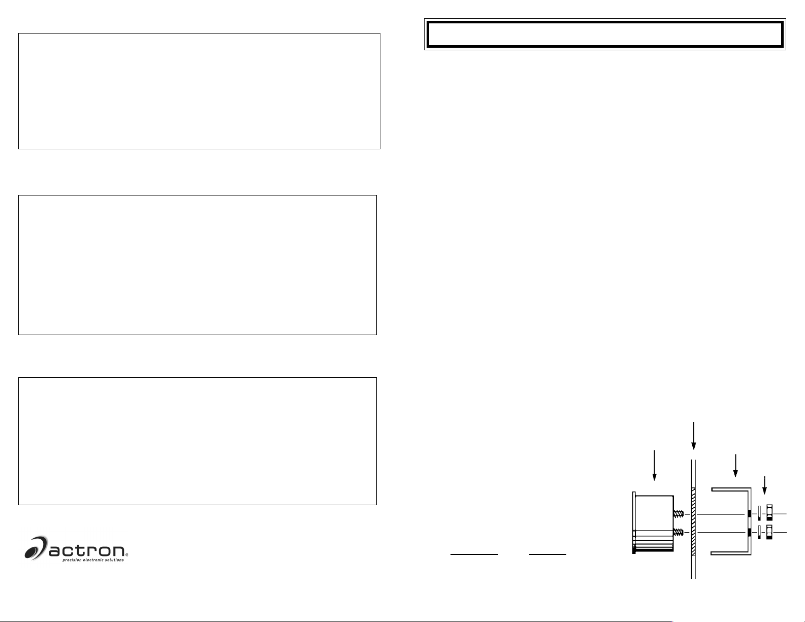
DASHBOARD
Diagram 1
Top View
1
GAUGE
BRACKET
NUTS &
WASHERS
Page 2
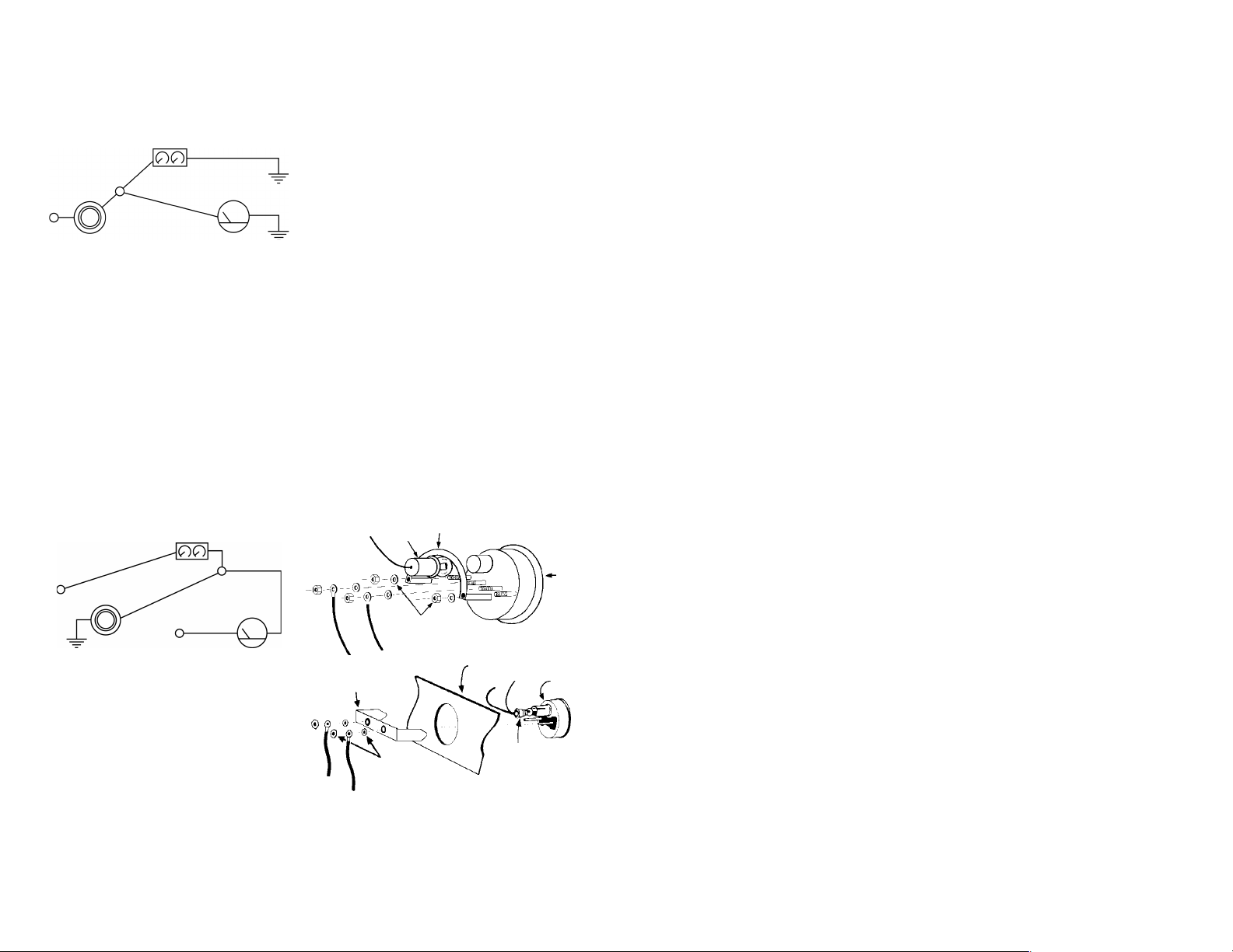
3. Dimmer Control.
For dash lighting dimmers that control the
positive side (Diagram 2A) of the lighting circuit:
Diagram 2A
For Positive Dimmer Controls
DASH LIGHTING
DIMMER
CONTROL
+12 VOLTS
RED
- For Two-wire Bulb Holder -
Connect the red wire into the circuit between
the dimmer control and the dash lights. Connect
the black wire to a good electrical ground.
- For One-wire Bulb Holder -
Connect the one wire into the circuit between
the dimmer control and the dash lights. Obtain a
length of 18-gauge insulated copper wire and
connect one end of the wire to a good electrical
ground source and the other end to one of the
mounting bracket posts.
For dash lighting dimmers that control the
grounded side (Diagram 2B) of the lighting circuit:
Diagram 2B
For Ground Dimmer Controls
DASH LIGHTING
GROUND
GAUGE
BLACK/
GROUND
GROUND
4. Refer to specific instructions for the gauge
you are installing. They explain other connections that should be made before mounting is completed.
5. Insert the gauge into the mounting panel or
hole.
6. Insert the bulb holder into the bulb socket on
the back of the gauge.
7. Install the appropriate mounting bracket (Diagram 1: insulated or non-insulated) over the
mounting posts (Diagram 3), slide on washer,
plus a lock washer if supplied, and tighten
the nut with only light pressure. If the gauge
is an electrical model, be sure you use a
bracket that has grommets to insulate the
posts from the mounting bracket. This does
not apply to gauges using separate bracket
mounting posts from the posts used for wire
connections.
8. Position the gauge for best visibility and appearance, then tighten the bracket nuts with
moderate pressure. Do not over- tighten these
nuts when using an insulated bracket. Excess pressure can distort the grommets causing them to crack and short the wiring, even
months after installation.
9. Refer to the specific instructions for the gauge
you are now installing to complete any other
connections.
Diagram 3
Electrical Gauges Shown
U-BRACKET
LIGHT
+12 VOLTS
GROUND
DIMMER
CONTROL
+12 VOLTS
BLACK/GROUND
RED
GAUGE
- For Two-wire Bulb Holder -
Connect the black wire into the circuit between
the dimmer control and the dash lights. Connect
the red wire to the fuse box so that the wire only
receives +12-volt power when the dash lights are
turned on.
- For One-wire Bulb Holder -
Connect the wire to the fuse box so it receives
only +12-volt power when the dash lights are on.
Obtain a length of 18-gauge insulated copper wire
and connect one end to the gauge mounting
bracket or panel. Connect the other end of the
wire into the circuit between the dimmer control
and the dash lights. Insulate the gauge and
bracket from grounded surfaces.
GAUGE
NUTS &
WASHERS
INSULATED
U-BRACKET
NUTS &
WASHERS
2
DASHBOARD
GAUGE
LIGHT
7
Page 3

Si vous avez à percer un trou, voici les
dimensions:
STYLE TAILLE DE
D'APPAREIL TROU
38,0 mm (1-1/2") 41,3 mm (1-5/8")
50,1 mm (2") 52,4 mm (2-1/16")
66,7 mm (2-5/8") 66,7 mm (2-5/8")
3. Commande de gradateur.
Pour la commande d'intensité d'éclairage du
tableau de bord, qui contrôle le côté positif
(Schéma 2A) du circuit d'éclairage.
ÉCLAIRAGE DES INSTRUMENTS
MASSE
NOIR/MASSE
MASSE
+12 V
COMMANDE DE GRADATEUR
ROUGE
INDICATEUR
Schéma 2A
Pour Les Cdes D'intensité D'éclairage Sur Positif
- Support D'ampoule À 2 Fils -
Connectez le fil rouge dans le circuit entre le
contrôle d'intensité et les ampoules d'éclairage.
Connectez le fil noir sur une bonne masse
électrique.
- Support D'ampoule À 1fil -
Connectez le fil unique dans le circuit entre le
contrôle d'intensité et les ampoules d'éclairage.
Trouvez une longueur de fil cuivre isolé de calibre 18, connectez-en une extrémité sur une bonne
masse électrique et l'autre sur l'un des montants
du support de montage.
ÉCLAIRAGE DES INSTRUMENTS
NOIR/MASSE
+12
COMMANDE DE
V
GRADATEUR
MASSE
+12 V
ROUGE
INDICATEUR
Schéma 2B
Pour Les Cdes D'intensité D'éclairage Sur Masse
Pour la commande d'intensité d'éclairage
du tableau de bord, qui contrôle le côté
masse (Schéma 2B) du circuit d'éclairage:
- Support D'ampoule À 2 Fils -
Connectez le fil noir dans le circuit entre le
contrôle d'intensité et les ampoules d'éclairage.
Connectez le fil rouge sur une sortie de boîte à
fusibles où il ne recevra du +12 V que lorsque le
tableau de bord est éclairé.
- Support D'ampoule À 1fil -
Connectez le fil unique sur une sortie de boîte à
fusibles où il ne recevra du +12 V que lorsque le
tableau de bord est éclairé. Trouvez une longueur
de fil cuivre isolé de calibre 18, connectez-en une
extrémité sur l'un des montants du support de
montage. Connectez son autre extrémité dans le
circuit entre le contrôle d'intensité et les ampoules
d'éclairage. Isolez l'appareil de mesure et son
support de toutes surfaces à la masse.
4. Reportez-vous aux instructions spécifiques
pour l'appareil que vous installez. Elles
expliquent lesautresliaisons que vous devez
réaliser avant de finir le montage.
5. Insérez l'appareil dans le tableau de
montage ou le trou.
6. Insérez la douille d'ampoule dans le fourreau
d'éclairage à l'arrière de l'appareil.
7. Installez le support de montage approprié
(Schéma 1 : isolé ou non isolé) par dessus
les montants Schéma 3), glissez à chaque
une rondelle, plus une rondelle frein s'il y en
a de fournies, et serrez sans forcer la fixation
avec un écrou. Si l'appareil de mesure est du
type électrique, assurez-vous que vous
utilisez un support qui possède des rondelles
isolantes pour séparer les montants du support de montage. Cetteprécaution ne
s'applique pas aux appareils qui utilisent des
montants séparés pour fixation sur le support
de ceux utilisés pour raccorder les fils
électriques.
8. Positionnez l'appareil pour la meilleure
visibilité et apparence, puis serrez les écrous
de montants avec une pression raisonnable.
Ne serrez pas trop quand le support est isolé.
Un serrage excessif peut déformé les
rondelles isolantes, ce qui peut provoquer leur
cassure et un court-circuit, même des mois
Schéma 3
après l'installation.
Les Appareils Montrés Sont Électriques
9. Reportez-vous aux instructions spécifiques
pour l'appareil que vous installez maintenant
ÉCLAIRAGE
pour terminer ses éventuelles autres
SUPPORT EN U
connexions.
APPAREIL
ÉCROUS ET
RONDELLES
TABLEAU DE
BORD
SUPPORT
EN U ISOLÉ
ÉCROUS ET
RONDELLES
APPAREIL
ÉCLAIRAGE
6
INSTRUCCIONES DE INSTALACION
DE LOS INDICADORES
INSTRUCCIONES GENERALES DE MONTAJE
El fabricante produce una línea completa de
indicadores con muchos estilos diferentes.
38 mm Indicadores
50 mm Indicadores
67 mm Indicadores
(Vea la página 4 para los tamaños de
los orificios)
Los indicadores le permiten monitorear el estado
MOTORES CONTROLADOS POR MICROPROCESADORES
Muchos de los vehículos más nuevos emplean
microprocesadores que controlan la mayoría de
las funciones del motor y eléctricas. Los
microprocesadores son componentes eléctricos
muy sensibles. Antes de instalar cualquier equipo
de otra fabricación consulte con el fabricante del
vehículo o manual del taller para asegurarse que
no resultará pipo averías.
Algunos de esos vehículos más nuevos usan
ventiladores enfriadores eléctricos o controles por
microprocesador del motor que dependen de
lecturas de las unidades emisoras del equipo
INSTALACION Y PRECAUCIONES DE SEGURIDAD
1. Antes de proceder lea todas las instrucciones
para su indicador.
2. Asegúrese que el indicador es adecuado
para su vehículo.
¿Cubre el alcance del indicador el alcance
operativo del vehículo?
¿Alcanzarán las tuberías de los indicadores
mecánicos desde el punto de conexión del
motor al indicador (¿no pueden extenderse
los indicadores de temperatura?)
¿Es el sistema eléctrico del vehículo de tensión
12 V y está conectado negativamente a
tierra?
Todos los indicadores pueden montarse en una
superficie de su selección o dentro de un panel.
Nosotros produce paneles de montaje de indicador
simples, dobles y triples para indicadores de todos
los tamaños. Algunos paneles tienen acabados
en negro o cromo. Para los indicadores de 66,7
mm está disponible una copa de montaje
completamente cromada
1. Localice una ubicación de montaje del
indicador donde será visible desde una
posición normal de manejo (los indicadores
de presión de combustible no deben montarse
nunca dentro del interior del vehículo).
2. Si usted está usando un panel de montaje,
móntelo en la ubicación seleccionada con los
tornillos provistos.
MONTAJE DEL INDICADOR
de su vehículo e informarle acerca de cuán bien
se desempeña. Si hubiera problemas, usted
puede detectarlos inmediatamente antes de que
se conviertan pipo graves. Las luces de
advertencia le informan cuando el problema
requiere atención inmediata solamente. Usted
notará que la adición de esos indicadores le
proporcionará más tranquilidad y comodidad de
manejo.
original para una operación correcta. Si su
vehículo es uno de ellos usted NO PUEDE
reemplazar el emisor(es) por ningún otro. Usted
puede agregar un emisor adicional de presión
de aceite con un Juego de Adaptador pipo T
pero la única manera posible de instalar un emisor
de temperatura de agua no OEM
(MANUFACPURA DE EQUIPO) es instalar el
nuevo emisor pipo una ubicación diferente,
reteniendo la unidad OEM pipo su ubicación original. Para verificar si esto es posible consulte
con el fabricante o distribuidor del vehículo.
3. ¿Se recomienda que se desconecte el cable
de conexión a tierra antes de efectuar
cualquier trabajo eléctrico, especialmente al
instalar amperímetros o voltímetros?
4. Encamine todo el cableado y las tuberías de
los indicadores alejado de los acoples y del
calor intenso o piezas móviles.
5. Nunca fume mientras trabaja en su vehículo
y mantenga siempre un extintor de incendios
cerca. Debe tener una clasificación nominal
para incendios ocasionados por gas/materias
químicas/eléctricos.
6. Nunca coloque herramientas sobre la batería
ni use joyas durante el trabajo eléctrico para
evitar cortocircuitos eléctricos peligrosos.
Diagrama 1
INDICADOR
TABLERO
SOPORTE
3
TUERCAS Y
ARANDELAS
Page 4

Si usted está perforando un orificio hágalo así:
ESTILO DEL TAMAÑODEL
INDICADOR ORIFICIO
38 mm 41 mm
50,1 mm 53 mm
66,7 mm 67 mm
3. Control del atenuador.
Para atenuadores de iluminación del tablero
que controlan el lado positivo (Diagrama 2A)
del circuito de iluminación:
Diagrama 2A
Para Controles Positivos Del Atenuador
ILUMINACION DEL TABLERO
CONEXION A
TENSIÓN +12
CONTROL DEL
ROJO
INDICADOR
CONEXION
CONEXION
- Para Sujetador De Bulbo De Dos Cables -
Conecte el cable rojo dentro del circuito entre el
control del atenuador y las luces del tablero.
Conecte el cable negro a una conexión a tierra
en buen estado.
- Para Sujetador De Bulbo De Un Solo Cable -
Conecte a un cable dentro del circuito entre el
control del atenuador y las luces del tablero.
Obtenga un tramo de cable aislado de cobre de
calibre 18 y conecte un extremo del cable a una
fuente de conexión eléctrica a tierra en buen
estado y el otro extremo a uno de los postes de
soporte de montaje.
Para los atenuadores de iluminación de
tablero que controlan el lado conectado a
tierra (Diagrama 2B) del circuito de
iluminación.
Diagrama 2B
Para Los Controles De Atenuador Conectados a
TENSIÓN
+12 V
CONTROL DEL
ATENUADOR
CONEXION A TIERRA INDICADOR
- Para Sujetador De Bulbo De Dos Cables -
Conecte el cable negro dentro del circuito entre
el control del atenuador y las luces del tablero.
Conecte el cable rojo a la caja de fusibles de
manera que el cable reciba potencia de tensión
+12 V solamente cuando se enciendan las luces
del tablero.
- Para Sujetador De Bulbo De Un Cable -
Conecte el cable a la caja de fusibles de manera
que reciba potencia de tensión +12 V solamente
ILUMINACION DEL TABLERO
TENSIÓN
+12 V
ROJO
CONEXION
NEGRAATIERRA
cuando se encienden las luces del tablero.
Obtenga un tramo de cable aislado de cobre de
calibre 18 y conecte un extremo del cable al
soporte de montaje del indicador o al panel.
Conecte el otro extremo del cable dentro del
circuito entre el control del atenuador y las luces
del tablero. Aísle el indicador y el soporte
de las superficies conectadas a tierra.
4. Refiérase a las instrucciones específicas
para el indicador que está instalando. Ellas
explican otras conexiones que deben
efectuarse antes de completar el montaje.
5. Inserte el indicador dentro del panel u orificio
de montaje.
6. Inserte el sujetador del bulbo dentro del
receptáculo del bulbo en el reverso del
indicador.
7. Instale el soporte adecuado de montaje
(Diagrama 1: aislado o no aislado) sobre los
postes de montaje (Diagrama 3), deslice la
arandela, además de una arandela de
seguridad si ha sido provista, y ajuste la
tuerca con una presión leve solamente. Si el
indicador es un modelo eléctrico, asegúrese
de usar un soporte que tenga arandelaspara
aislar los postes del soporte de montaje. Si
esto no se aplica a los indicadores queusan
postes separados de soporte de mon-taje
de los postes usados para las conexiones
del cable.
8. Coloque en posición el indicador para obtener
la mejor visibilidad y apariencia, a
continuación ajuste las tuercas del soporte
con una presión moderada. No ajuste en
exceso esas tuercas al usar un soporte
aislado. Una presión excesiva puede
distorsionar las arandelas causando que se
agrieten y causar cortocircuitos en el cable,
aun después de varios meses de la
instalación.
9. Para completar otras conexiones, refiérase
a las instrucciones específicas para el
indicador que está instalando ahora.
Diagrama 3
Indicadores Eléctricos Ilustrados
SOPORTE EN U
LUZ
INDICADOR
TUERCAS Y
ARANDELAS
SOPORTE EN U
AISLADO
4
TUERCAS Y
ARANDELAS
TABLERO
INDICADOR
LUZ
INSTRUCTIONS D'INSTALLATION
INSTRUCTIONS GÉNÉRALES DE MONTAGE
Le constructeur produit une gamme complète
d'appareils de mesure avec différents styles:
38,0 mm (1-1/2") Appareils
50,1 mm (2") Appareils
66,7 mm (2-5/8") Appareils
(Voir en page 6 les tailles de trous)
Les appareils de mesure vous permettent de
contrôler l'état de votre véhicule et de savoir dans
MOTEURS PILOTÉS PAR MICROPROCESSEUR
De nombreux véhicules récents utilisent des
microprocesseurs pour commander la plupart des
fonctions de moteur et électriques. Ces
microprocesseurs sont des composants
électriques très fragiles. Avant d'installer n'importe
quel équipement du marché des accessoires,
consultez le fabricant du véhicule ou le manuel
de réparations pour vous assurer qu'aucun
dommage n'en résultera. Certains de ces
derniers véhicules utilisent des ventilateurs de
refroidissement électriques ou des commandes
moteur à microprocesseur qui dépendent pour
INSTALLATION ET PRÉCAUTIONS DE SÉCURITÉ
1. Lisez toutes les instructions relatives à votre
appareil de mesure avant de commencer.
2. Assurez-vous que l'appareil convient bien à
votre véhicule:
Sa plage couvre-t-elle la plage de service du
véhicule?
Est-ce que la gaine de l'appareil est assez
longue pour aller du point de capture au
moteur jusqu'à l'emplacement de l'affichage
(les liaisons de thermomètres ne peuvent pas
être rallongés)?
Le système électrique du véhicule est-il bien
en 12 V avec négatif à la masse?
3. Il est recommandé que le câble de masse de
la batterie soit débranché avant d'exécuter
MONTAGE DE L'APPAREIL
Tous les appareils de mesure peuvent se monter
sur la surface de votre choix ou sur tableau. Des
panneaux pour un seul, deux ou trois appareils
sont disponibles pour toutes leurs tailles. Certains
panneaux ont une finition noire ou chromée. Une
bague extérieure de montage entièrement
chromée est disponible pour les appareils en 66,7
mm.
1. Choisissez un emplacement pour monter
l'appareil d'où il sera visible en position de
conduite normale (les indicateur de pression
de carburant ne doivent jamais être montés
dans l'habitacle du véhicule).
2. Si vous utilisez un tableau de montage, fixez-
le dans la zone choisie avec les vis fournies.
quelle mesure il fonctionne bien. S'il y avait des
problèmes quelconques, vous pouvez les détecter
tout de suite avant qu'ils ne s'aggravent. Des
voyants de signalisation ne vous préviennent que
quand les problèmes nécessitent une attention
immédiate. Vous constaterez que l'ajout des ces
appareils agira sur votre tranquillité d'esprit et
votre confort de conduite.
leur bon fonctionnement des lectures des unités
d'équipements d'origine. Si votre véhicule est l'un
de ceux-là, VOUS NE POUVEZ PAS remplacer
un appareil émetteur par un autre. Vous pouvez
installer un capteur-émetteur de pression d'huile
supplémentaire avec un kit adaptateur en té, mais
la seule façon d'installer un capteur-émetteur de
température d'eau qui ne soit pas du matériel
d'origine et de le placer à autre endroit, en laissant
celui d'origine à sa place. Vérifiez auprès du
constructeur du véhicule ou de son
concessionnaire pour savoir ce qui est possible.
n'importe quelle intervention. électrique, tout
spécialement à l'installation d'ampèremètres
ou voltmètres.
4. Faites passez le câblage et la tuyauterie
d'appareil de mesure à l'écart des tringleries,
hautes températures et pièces mobiles.
5. Ne fumez jamais quand vous travaillez sur le
véhicule, et ayez toujours un extincteur à
portée de main. Il doit être classé pour les
incendies d'origine gazeuse/chimique/
électrique.
6. Ne laissez jamais d'outil sur le dessus de la
batterie et ne portez pas de bijoux durant votre
intervention électrique, pour éviter de graves
court-circuits.
Schéma 1
Vue De Dessus
INDICATEUR
TABLEAU DE BORD
SUPPORT
ÉCROUS ET
RONDELLES
5
 Loading...