

Page 1
CRT COLOR ANALYZER
CRT
Page 2
CRT COLOR ANALYZER
CA-100
Application
Chromaticity
Adjustment, Inspection
White-balance
Adjustment, Inspection
Cut-off
Adjustment, Inspection
Plus
Select the probe among the following four types.
Measuring Probe (Cable length: 2 m)
Measuring Probe (Cable length: 5 m)
High luminance Measuring Probe (Cable length: 2 m)
High luminance Measuring Probe (Cable length: 5 m)
FASTER
ACCURATE
LOW LUMINANCE
∗Up to five probes can be connected to a single main body. Regular measuring
probes and high luminance measuring probes can be connected simultaneously to a
single main body.
(To connect multiple probes, the optional four-point extension board (CA-B04) is
necessary.)
The luminance and chromaticity of display can be
measured as fast as 20 times per second (maximum),
reducing the time for automatic adjustment.
Accuracy of ±0.002 for White,±0.004 for R,G,B
(Chromaticity)
Precise measurement can be obtained at low luminance
of 0.05 cd/m
Range of luminance for chromaticity measurement: 0.05 to 1000 cd/m2(Measuring probe)
2
and reducing the cycle time.
2
0.05 to 2000 cd/m
(High luminance measuring probe)
EASY TO USE
Compatible with CA-100.
Compact nearly A4 size (width and depth).
Sample software is bundled; you can control easily by PC.
Expandable up to 5 sensing probes.
Page 3

Display Unit
CA-100Plus
Software
made with SDK
Pattern Generator
This is PC software created using standard accessory software CA-SDK and
others, and it controls the display drivers such as CA-100Plus and pattern
generator to measure the white or black luminance.
The white and black correction coefficients are obtained from the measured
luminance values of the display, and they are written to the correction circuit of
the display.
Pattern
Signal
Writing gain
and cutoff level
Command to
CA-100Plus
Data from CA
CH01EXT FaP1
[EXTD-1.50]
POWER
0-CAL
MODE REMOTE HOLD MR
MEMORYCH
PQRS7TUV8WXYZ
MENU
ALPHA
9
GHI4JKL5MNO LOCK
6
CAL
White1ABC2DEF-SPACE
3
ENTER
Red0Green.Blue
ON
OFF
x
y
v
∆x
∆y
∆Lv
User's own matrix correction factor is set to the memory
channels by measuring three monochrome colors (R, G,
B and W) of known values and setting the obtained
calibration values (xyLv) and emission characteristic to
the instrument. Once this factor is set, the measured
values will be displayed after correction by this factor and
output each time measurement is taken.
Performing matrix calibration enables high-accuracy
measurements of displays that provide colors through
additive color mixing of three monochrome colors (R, G
and B).
Since the matrix correction factor obtained from Minolta's
calibration standard has been set, measured values
calculated based on this factor will be acquired when this
instrument is used for the first time since shipment from
the factory.
You can select the "CA-100-compatible mode" and the
"CA-200 mode" with the CA-100Plus. In the CA-100-
compatible mode, compatibility with the measurement
data of CRT color analyzer CA-100 and compatibility with
the RS-232C communication environment of the CA-100
are obtained, and in the CA-200 mode, standard
accessory software CA-SDK can be used.
CA-100Plus is for those who already have CA-100 and
who want to maintain data compatibility, or for those who
have established a communication environment
including CA-100 and who intend to use the new analyzer.
l
Standard accessory SDK helps create software easily according to needs.
l
Sample software is bundled; you can start data collection easily.
PC Software for Color Analyzer CA-SDK (Standard accessory)
∗Windows®and Excel®are a trademark of Microsoft Corporation
in the USA and other countries.
Required system
OS Windows®98,2000,ME,XP (x64 Edition not supported)
PC: COM Port support
Cal
CA-100Plus is corrected in the matrix calibration method
using Konica Minolta's spectroradiometer CS-1000A.
Color
The measurement data of CA-100Plus is acquired into
the PC.
Drift tests, repeatability test and so on can be performed
easyly. The acquired data can be read with EXCEL®or
other spreadsheet software.
Contrast
Multi-point measurement (5, 9, or 25 points) is made for
white uniformity measurement.
Display sample
Sample software (Standard)
White balance and cutoff adjustment system CA-100-compatible mode
Matrix Calibration
Page 4
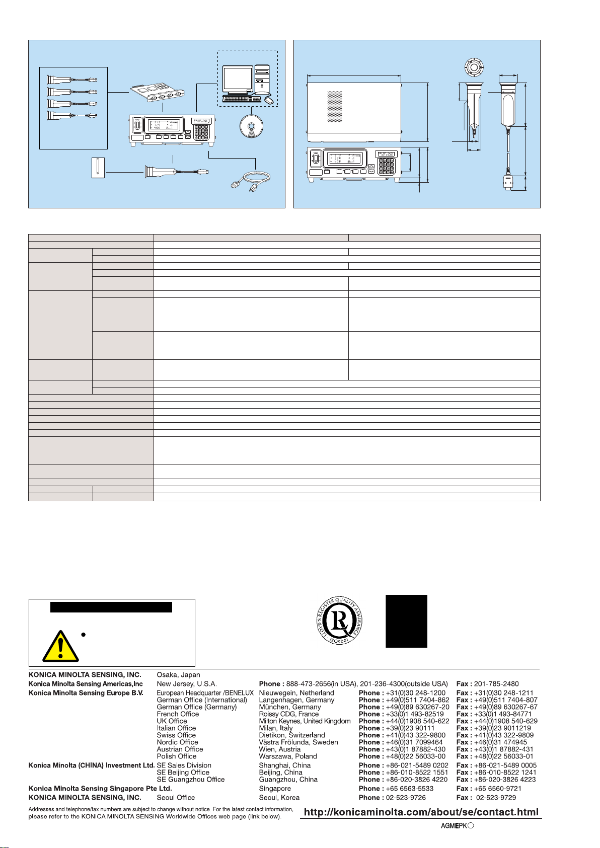
Dimensions
340
216
127
11017
70
1422 m / 5 m47.4
φ60
30.2
φ44
ISO 5
mm screw
(depth : 6
mm)
60
φ
45
(Units : mm)
Receptor
Display range Luminance
Chromaticity
*1 The chromaticity and luminance are measured under Konica Minolta’s condition (standard CRT (6500 K) is used).
*2 The luminance for monochrome is measured when the reading of luminance for white is 40.00 cd/m2.
*3
Measuring probe connected to probe connector P1 only,used USB (used RS-232C
Baud rate: 38400 bps
)
*4 At the CA-200 mode
� Select the probe among the four types.
� Specifications are subject to change without notice.
Specifications
Detector : Silicon photo cell
0.05 to 1000 cd/m
2
±2 %±1 digit of reading (temperature : 23°C±2°C, relative humidity : (40±10)%)
0.05 to 1000 cd/m
2
xyLv, T∆uvLv, RGB, XYZ, u'v'Lv
∆x, ∆y, ∆Lv, R/G, B/G, ∆G, ∆R, B/R, G/R
NTSC, PAL, EXT, UNIV, INT
Vertical syncronizing frequency : 40 to 200 Hz
100 channels
Standard function
0 to 28°C : relative humidity 70 % or less with no condensation
28 to 40°C : relative humidity 40 % or less with no condensation
100-240 V~, 50-60 Hz 50 VA
340 × 127 × 216 mm (W × H × D), φ45 × 142 mm
3.58 kg, 285 g
0.01 to 1000 cd/m
2
Displayed in 4 or 3-digit value (Can be chosen)
0.05 to 1000 cd/m
2
0.2 %+1 digit (2 σ)
0.05 to 0.19 cd/m2±0.006 (for white)
0.20 to 0.49 cd/m2±0.004 (for white)
0.50 to 1000 cd/m2±0.003 (for white)
40.00 cd/m
2
±0.002 (for white), ±0.004 (for monochrome)*2
0.05 to 0.19 cd/m20.006 (2 σ)
0.20 to 0.49 cd/m20.002 (2 σ)
0.50 to 1000 cd/m20.001 (2 σ)
0.05 to 0.99 cd/m25 measurements/sec. (4.5 measurements / sec.)
*4
1.00
to 1000 cd/m220 measurements/sec. (17 measurements / sec.)
*4
USB (1.1 conformity) , RS-232C (38,400 bps or below)
Max. 5 points (Use 4-Probe Expansion Board CA-B04)
Temperature : 10 to 28°C; relative humidity 70 % or less with no condensation
Luminance change : ±2 % ±1 digit of reading for white
Chromaticity change : ±0.002 for white, ±0.006 for monochrome
from reading of Konica Minolta's standard CRT*1, 40.00 cd/m2, with 23°C 40 %
0.05 to 2000 cd/m
2
0.05 to 2000 cd/m
2
0.01 to 2000 cd/m
2
0.05 to 2000 cd/m
2
0.2 %+1 digit (2 σ)
0.05 to 0.09 cd/m2±0.008 (for white)
0.10 to 0.39 cd/m2±0.006 (for white)
0.40 to 0.99 cd/m2±0.004 (for white)
1.00 to 2000 cd/m2±0.003 (for white)
40.00 cd/m
2
±0.002 (for white), ±0.004 (for monochrome)*2
0.05 to 0.09 cd/m20.009 (2 σ)
0.10 to 0.39 cd/m20.006 (2 σ)
0.40 to 0.99 cd/m20.002 (2 σ)
1.00 to 2000 cd/m20.001 (2 σ)
0.05 to 1.99 cd/m25 measurements/sec. (4.5 measurements / sec.)
*4
2.00
to 2000 cd/m220 measurements/sec. (17 measurements / sec.)
*4
System Diagram
Measuring Probe (2 m) CA-P02
Measuring Probe (5 m) CA-P05
High luminance Measuring Probe (2 m) CA-PH02
High luminance Measuring Probe (5 m) CA-PH05
(Optional)
PC (Commercially available)
PC-AT compatible
CA-100Plus
AC Power Cord (Standard)
PC Software for Color Analyzer
CA-SDK (Standard)
4-Probe Expansion Board
CA-B04
(Optional)
Multi-Probe
Measuring Probe Holder
CA-A11 (Standard)
CA-100Plus(Measuring Probe 2 m or 5 m)
CA-100Plus(High luminance Measuring Probe 2 m or 5 m)
Measuring Probe (2 m) CA-P02
Measuring Probe (5 m) CA-P05
High luminance Measuring Probe (2 m) CA-PH02
High luminance Measuring Probe (5 m) CA-PH05
Luminance Measurement range
Accuracy (for white)*1
Repeatability *1
Chromaticity Measurement range
Accuracy *1
Repeatability *1
Measurement speed xyLv
Display Digital
Analog
SYNC mode
Object under measurement
Memory channel
Analyzer function
Interface
Multi-point Measurement
Operating temperature/humidity range
Storage temperature/humidity range
Input voltage range
Size Mainbody, Probe
Weight Mainbody, Probe
(temperature : 23°C±2°C,
relative humidity : (40±10)%)
*3
AGMEP
K
Printed in Japan9242-4885-12
©2003 KONICA MINOLTA SENSING, INC.
SAFETY PRECAUTIONS
9
For correct use and for your safety, be sure to read
the instruction manual before using the instrument.
Always connect the instrument to the
specified power supply voltage.
Improper connection may cause a fire
or electric shock.
Certificate No : JQA-E-80027
RegistrationDate : March 12, 1997
Certificate No : YKA 0937154
RegistrationDate : March 3,1995
 Loading...