3D Connexion 466-1513-01 User Manual

GE Security
g
www.GE-Security.com
Part Numbers: 60-792-01-95R 60-734-01 60-801-01
T e s t S y s te m W e e k ly
A
B
C
D
p r e s s b o t h
p r e s s b o t h
p r e s s b o t h
O f f
N o D e la y
F e a t u r e s
S t a tu s
*
466-1513-01 Rev F June 2004
S t a y
2
S i le n t
5
S y s t e m
8
L ig h ts
0 #
B y p a s s
A w a y
3
6
M e n u
9
S y s t e m i s O K
1
4
7
Q u ic k G u id e
D is a r m S y s t e m / C a n c e l A la r m
P r es s 1 + C O D E .
A r m t o S T A Y
1
C l o s e a ll p ro te c te d d o o r s a n d w i n d o w s .
2
P r es s 2 + C O D E .
3
P r es s 4 t o a r m d e la y d o o r s i n st a n t ly , if d e si r ed .
A r m t o A W A Y
1
C l o s e a ll p ro te c te d d o o r s a n d w i n d o w s .
2
P r es s 3 + C O D E .
3
E x i t p r em is e s t h r o u g h d el a y d oo r .
Z o n e / S e n s o r N u m b e r
0 1 0 2 0 3 0 4 0 5 0 6 0 7
Concord
User Instructions
B y p as s S e n so rs
1
A r m s ys t e m t o d e s ir e d le v e l.
2
P r es s B Y P A S S + C O D E + S en so r N o .
T u r n C H I M E O n / O ff
1
M ak e su r e sy s t em i s d i s a rm ed .
2
P r es s 7 + 1 t o tu r n C H IM E o n o r o f f.
P r o g r a m U se r S e t t in g s
1
M ak e su r e sy s t em i s d i s a rm ed .
2
P r es s A o r B t o s c r o ll t h r o u g h m e n u s . P r es s # t o s e le c t o p t i o n o r ac c e p t e n t r P r es s to d e se l e ct o p t io n o r c a n c e l e n t ry . P r es s 1 f o r O FF ; p r e s s 2 fo r O N ; p r es s 0 - 9 fo r o th er e n t r ie s .
0 8 0 9 1 0 1 1 1 2 1 3 1 4
A r m e d
R e a d y
S ta y
T e st S y s te m W e e k l y
y .
Q u ic k E x i t
O f f
A
p r e s s b o t h
N o D e la y
415
B
p r e s s b o t h
F e a tu r e s
C
7
p r e s s b o t h
S ta t u s
D
*
2
S il e n t
S y s te m
8
L ig h t s
0 #
B y p a s s
A w a y
3
6
M e n u
9
Notices
FCC Part 15 Information to the User
Changes or modifications not expressly approved by GE Security can void the user’s authority to operate the equipment.
FCC Part 15 Class B
This equipment has been tested and found to comply with the limits for a Class B digital device, pursuant to part 15 of the FCC Rules. These limits are designed to provide reasonable protection against interference in a residential installation.
This equipment generates, uses, and can radiate radio frequency energy and, if not installed and used in accordance with the instructions , may caus e harmful interference to radio communications. However, there is no guarantee that interference will not occur in a particular installation.
If this equipment does cause harmful interference to radio or television reception, which can be determined by turning the equipment off and on, the user is encouraged to try to correct the interference by one or more of the following measures:
Reorient or relocate the receiving antenna.
Increase the separation between the equipment and receiver.
Connect the affected equipment and the panel receiver to separate outlets, on different branch circuits.
Consult the dealer or an experienced radio/TV technician for help.
ACTA Part 68
This equipment complies with Part 68 of the FCC Rules. Located on this equipment is a label that contains, among other information, the FCC registration num­ber and the ringer equivalence number (REN) for this equipment. If requested, this information must be provided to the telephone company.
FCC Part 68 Registration No. B4ZUSA-25644-AL-E The REN is used to determine the maximum number of devices that may be connected to your telephone line. Excessive RENs on a telephone line may result in
devices not ringing in response to an incoming call. In most areas, the sum of all device RENs should not exceed five (5.0). To be certain of the number of devices that may be connected to a line, as determined by the total RENs, contact the local telephone company . For products approved after July 23, 2001, the REN for this product is part of the product identifier that has the format US:AAAEQ##TXXXX. The digits represented by ## are the REN without a decimal point (e.g., 03 is a REN of 0.3). For earlier products, the REN is separately shown on the label.
A plug and jack used to connect this equipment to the premises wiring and telephone network must comply with the applicable FCC Part 68 rules and require­ments as adopted by ACTA. A compliant telephone cord and modular plug is provided with this product. It is designed to be connected to a compliant modular jack that is also compliant. See the Installation Instructions for details.
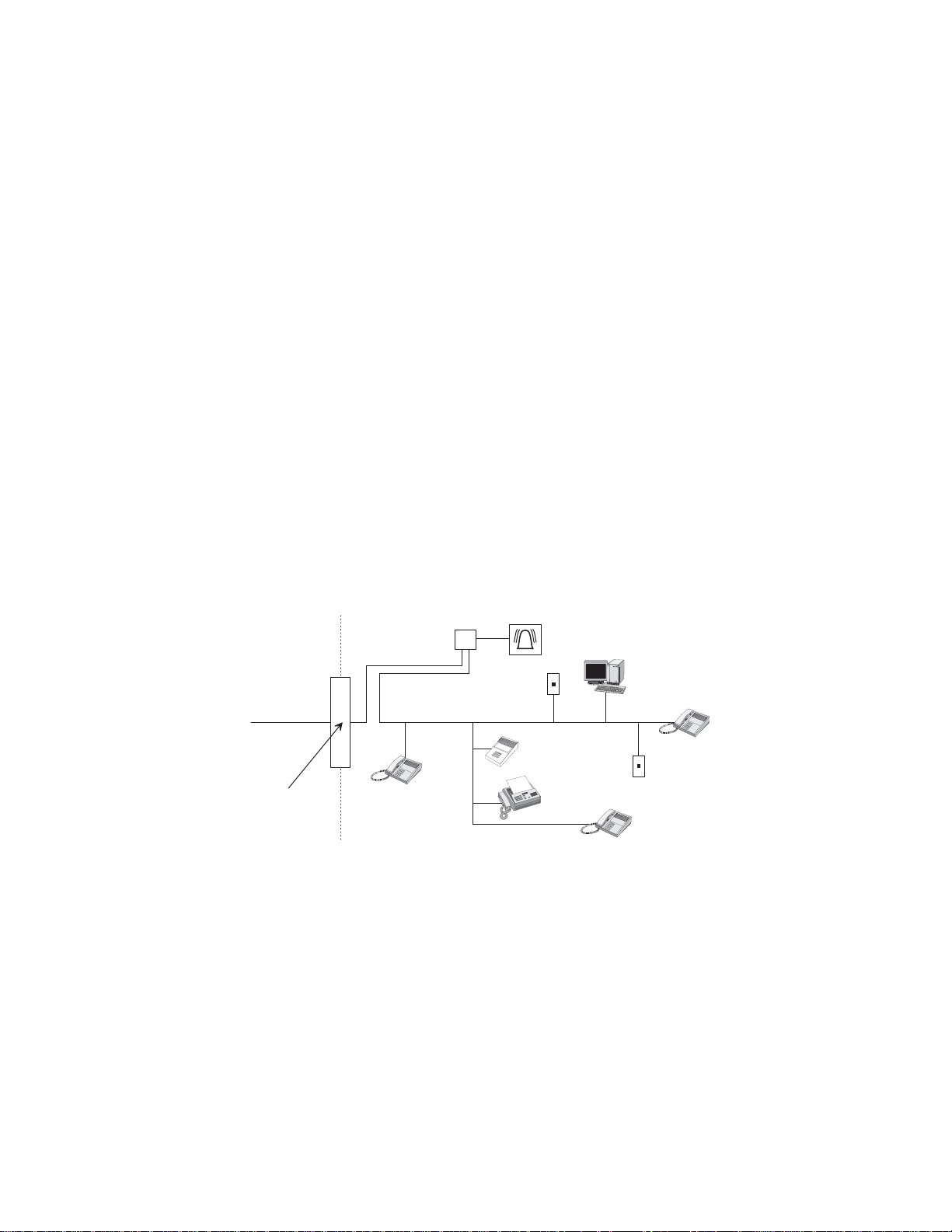
Alarm dialing equipment must be able to seize the telephone line and place a call in an emergency situation. It must be able to do this even if other equipment (telephone, answering system, computer modem, etc.) already has the telephone line in use. To do so, alarm dialing equipment must be connected to a properly installed RJ31X jack that is electrically in series and ahead of all other equipment attached to the same telephone line. Proper installation is depicted in the fol­lowing diagram. If you have any questions concerning these instructions, consult your local telephone company or a qualified installer about installing an RJ31X jack and alarm dialing equipment for you.
C u s t o m e r P r e m i s e s E q u i p m e n t a n d W i r i n g
N e t w o r k S e r v i c e P r o v i d e r ' s F a c i l i t i e s
R J 3 1 X
J a c k
R J - 1 1 J a c k
U n u s e d
A l a r m D i a l i n g E q u i p m e n t
C o m p u t e r
T e l e p h o n e L i n e
N e t w o r k D e m a r c a t i o n P o i n t
T e l e p h o n e
A n s w e r i n g S y s t e m
F a x M a c
h i n e
T e l e p h o n e
T e l e p h o n e
U n u s e d R J - 1 1 J a c k
If this equipment causes harm to the telephone network, the telephone company may temporarily disconnect your service. If possible, you will be notified in advance. When advance notice is not practical, you will be notified as soon as possible. You will also be advised of your right to file a complaint with the FCC.
The telephone company may make changes in its facilities, equipment, operations, or procedures that could affect the operation of the equipment. You will be given advance notice in order to maintain uninterrupted service.
If you experience trouble with this equipment, please contact the company that installed the equipment for service and/or repair information. The telephone com­pany may ask you to disconnect this equipment from the network until the problem has been corrected or you are sure that the equipment is not malfunctioning.
This equipment may not be used on coin service provided by the telephone company. Connection to party lines is subject to state tariffs.
Patent Information
This product and the use of this product may be covered by one or more of the following patents: 5,805,063, 5,872,512, 5,942,981, 5,686,896, 5,686,885, 4,855,713. Except expressly provided herein, the purchase of this product shall not constitute a license or otherwise provide a right to practice a method covered by any of the identified patents. GE Security hereby grants the purchaser of this product a limited, non-exclusive license to practice the methods patented in the identified patents solely with products manufactured, sold or licensed by GE Security. This license grant does not extend to the use of unlicensed, third party products with this product.
Commands at a Glance
D
Disarm the system. Cancel an accidental alarm.
Arm to Level 2—STAY.* 2 + CODE Arm to Level 3—AWAY.* 3 + CODE Send a police alarm. Press and hold both POLICE buttons for
Send an auxiliary alarm. Press and hold both AUXILIARY
Send a fire alarm. Press and hold both FIRE buttons for 2
Arm system with No Delay.*
1 + CODE CODE or 1 + CODE
2 seconds.
buttons for 2 seconds.
seconds.
8573G51A.
2 + CODE + 4 or 3 + CODE + 4
Arm system for Latchkey.* 2 + CODE + 6 or
3 + CODE + 6
Bypass a sensor.* Indirectly: 2 + CODE + # or
3 + CODE + #
Directly: # + CODE + Sensor Number
Arm system silently.*
5 + 2 + CODE or 5 + 3 + CODE
Arm system with exit lights off.*
Turn all lights on/off. 0 + 0 Turn specific lights on/off. 0 + Light number Check the system status. * for Short status or * + * for Full status Turn Chime on/off. 7 + 1 Turn Energy Saver on/off. 7 + 2 Disable local phone access.**
(This is a phone command only.)
Check alarm memory. Activate Output.*** 7 + 7 + Output number (1–6) View Event History
*If Quick Arm feature is on, access code is not required. See “Arming Your System”. **Installer can disable local phone control if desired. ***Must be set up by installer .
2 + CODE + 0 or 3 + CODE + 0
# + 7 + 3
or wait 5 seconds after picking up the phone
7 + 6
8 + CODE + 8
Contents
Getting to Know Your Security System 1
Overview..................................................................................................................................................... 1
Communicating with the Panel 2
Instructing the Panel ................................................................................................................................... 2
Touchpads—Your System Interface ................................................................ ........................................... 3
Beeps and LEDs— How Your System Talks to You.................................................................................. 3
Notification by Pager.................................................................................................................................. 4
What Happens in an Alarm Condition........................................................................................................ 4
Fire and Smoke Alarms .............................................................................................................................. 4
Panel........................................................................................................................................................ 1
Touchpads............................................................................................................................................... 1
Door/Window Sensors............................................................................................................................ 1
Motion Sensors....................................................................................................................................... 1
Environmental Sensors ........................................................................................................................... 2
Phone Interface and Voice Module......................................................................................................... 2
Energy Saving Module ........................................................................................................................... 2
SuperBus®2000 Cellular Backup Module............................................................................................. 2
SuperBus 2000 Wireless Gateway Module............................................................................................ 2
Alphanumeric Touchpads....................................................................................................................... 3
Fixed Display Touchpads........................................................................... ............................................. 3
Wireless Handheld Touchpad ................................................................................................................. 3
Keychain Touchpads............................................................................................................................... 3
Touchtone Phones. .......................................................................... ........................................................ 3
Panic Buttons.......................................................................................................................................... 3
Key Beeps............................................................................................................................................... 3
Status Beeps............................................................................................................................................ 3
LEDs....................................................................................................................................................... 4
Resetting Smoke Detectors..................................................................................................................... 5
Preventing Accidental Alarms 5
Aborting Accidental Alarms....................................................................................................................... 5
Guidelines for Preventing Accidental Alarms............................................................................................ 5
Basic System Operations 6
Arming Your System .................................................................................................................................. 6
Keychain Touchpad Arming................................................................................................................... 6
Arming Level 1—OFF............................................................................................................................ 6
Arming Level 2—STAY......................................................................................................................... 7
Arming Level 3—AWAY........................................................................................................................ 7
Quick Arm .............................................................................................................................................. 7
Quick Exit............................................................................................................................................... 8
Using the Chime Feature .............................. ...................................... ........................................................ 8
Chime-On-Close..................................................................................................................................... 8
Using the Voice Chime Feature .................... ...................................... ...................................... .................. 8
i
Exit and Entry Delay Times........................................................................................................................ 8
Exit Delay Example................................................................................................................................ 8
Entry Delay Example.............................................................................................................................. 9
Extended Delay........................................................................................................................................... 9
Exit Extension............................................................................................................................................. 9
No Delay—For Instant Alarm .................................................................................................................... 9
Auto STAY Arming Feature ............................................. ...................................... .................................. 10
Arming While a Door or Window is Open............................................................................................... 10
Bypassing a Sensor Directly................ ...................................... ...................................... ..................... 10
Bypassing a Sensor Indirectly............................................................................................................... 11
Was the Bypass Successful? ................................................................................................................. 11
Basic Light Control................................................................................................................................... 11
Basic Output Control ................................................................................................................................ 11
Checking the Status of Your System......................................................................................................... 12
Short System Status ................................................................................... ........................................... 12
Full System Status ................................................................................................................................ 12
Panic Alarms 12
Fire Panic Alarm....................... ...................................... .......................................................................... 13
Lighting During a Fire Panic Alarm..................................................................................................... 13
Police Panic Alarm ...................................................................... ............................................................. 13
Lighting During a Police Panic Alarm ................................................................................................. 13
Auxiliary Panic Alarm.............................................................................................................................. 13
Lighting During an Auxiliary Panic Alarm .......................................................................................... 13
Siren Time-out...... ...................................... .............................................................................................. 13
Access Codes 13
Programming Access Codes..................................................................................................................... 14
Access Code Integrity........................ .. .......................................................................... ....................... 14
System Master Code Privileges... ......................................................................... ................................ 14
Partition Master Code Privileges .......................................................................................................... 14
Regular User Code Privileges........................................................................ ....................................... 14
The Touchpad Tamper Feature............................................................................................................. 14
Changing or Erasing User Codes.............................................................................................................. 14
Changing a User Code................................................................................... ....................................... 14
Erasing a User Code ............................................................................................................................. 15
Assigning Code Attributes.................................................................... .................................................... 15
Assigning the Direct Bypassing Attribute ............................................................................................ 15
Assigning the Remote Access Attribute ............................................. .................................................. 15
Assigning the Partition Jump Attribute ............... ...................................... .................................... ....... 15
Assigning the System Test Attribute .................................................................................................... 16
Assigning the Latchkey Report Attribute............................................................................................. 16
Setting the Time and Date 16 Adjusting System Sounds and Touchpad Brightness 17
Arming Your System Silently................................................................................................................... 17
Silent Arming on Demand........ ...................................... ...................................................................... 17
Arming Always Silent .......................................................................................................................... 17
Adjusting the Touchpad Beeps (Fixed Display Touchpad Only)............................................................. 17
ii
Adjusting the System Status Voice Volume.............................................................................................. 17
Adjusting the Touchpad Display Brightness ........................................ .................................................... 18
Adjusting the Volume of the Wireless Siren.................................................... ......................................... 18
Using the Energy Saver Feature 18
Energy Saver Example.............................................................................................................................. 18
Setting the Energy Saver High and Low Temperature Settings ........................................................... 19
Notification by Pager 19
Pager Messages..................................................................................................................................... 20
Event Code in Page............................................................................................................................... 20
Sensor Number or User Number in Page.............................................................................................. 20
Account Number in Page...................................................................................................................... 21
Streamlining the Page Report ................................................................................. .............................. 21
Creating Time Schedules 21
Scheduling Consecutive Days .............................................................................................................. 21
One Day Rollover........ ......................................................................... ................................................ 22
Multiple Day Rollover.......................................................................................................................... 22
Attaching Time Schedules........................................................................................................................ 22
Time Schedules and Partitions.................................................................................................................. 23
Advanced Light Control 23
Controlling Lights By Time Schedule.............. ........................................................................................ 23
Controlling Lights with Sensors ............................................................................................................... 23
Installer Programmable Lighting.............................................................................................................. 24
Controlling Outputs by Time Schedule 24 Scheduled Arming 24 Opening and Closing Reports 25
When Will this Feature Be Active? .......................................................................................................... 25
Who Will Be Paged?................................................................................................................................. 25
What Will the Pager Report?................................................... ..................................... ............................ 25
Latchkey Paging 25
Page In the Event of........................................................................................................... ....................... 25
Who Will Be Paged?................................................................................................................................. 25
Who Can Send a Page?............................................................................................................................. 25
What Will the Pager Report?................................................... ..................................... ............................ 26
Latchkey Opening .................................... ...................................... ........................................................... 26
Basic Latchkey Opening....................................................................................................................... 26
Advanced Latchkey Opening....................................................................................... ......................... 26
Latchkey Closing...... ................................................................................................................................ 26
Assigning a Time Schedule to Latchkey Paging ...................................................................... ................ 26
iii
Applying the Latchkey Modifier ................................. ...................................... ....................................... 27
Notify by Exception 27
Page In the Event of........................................................................................................... ....................... 27
Who Will Be Paged?................................................................................................................................. 27
Who Can Send a Page?............................................................................................................................. 27
What Will the Pager Report?................................................... ..................................... ............................ 28
When Will this Feature Be Active? .......................................................................................................... 28
Assigning a Time Schedule to Exception Opening and Closing...... ........................................ ................ 28
The No Activity Feature 28 Using the Panel Download Feature 28 Using a Partitioned System 29
Global Settings.......................................................................................................................................... 29
Partition-Specific Settings ........................................................................................................................ 29
Jumping Partitions .................................................................................................................................... 29
Arming and Disarming the Other Partition........................................................................................... 30
Programming the Other Partition.......................................................................................................... 30
System Information 30 Viewing Event Buffer 30
Overview................................................................................................................................................... 30
Using a Touchtone Phone to Operate Your System 33
Phone Command Prefix............................................................................................................................ 33
Accessing the System from Off-site ......................................................................................................... 34
How the Panel Answers the Phone....................................................................................................... 34
Codes with Remote Access Capability...................................................... ........................................... 34
Touchtone Phone System Operation......................................................................................................... 34
Sending a Police Panic Alarm .................................................................................................................. 35
Phone Questions?...................................................................................................................................... 35
Testing the System 36
Automatic Test Features ............................................ ............................................................................... 36
Manual Tests............................................................................................................................................. 36
Sensor Test............................................................................................................................................ 36
Phone Communication Test.................................................................................................................. 37
Testing Sirens........................................................................................................................................ 38
Troubleshooting 38
Trouble Beeps and Trouble Messages...................................................................................................... 38
Silencing Trouble Beeps....................................................................................................................... 38
Common Questions and Answers............................................................................................................. 38
iv
Phone Issues ......................................................................................................................................... 39
g
Siren Issues........................................................................................................................................... 39
Lighting Issues................ .......................................................................................................... ... ......... 39
Appendix A: User Sheets 41
System Sensors....................... ...................................... ............................................................................ 41
User Codes.......................................................................................... ...................................................... 42
Touchpad Information................................................................................................................ .. ............ 43
Alphanumeric and Fixed Display Touchpads................................... ........................................ ............ 43
Keychain Touchpads ................................................................................. ........................................... 43
Accidental Smoke and Fire Alarms.......................................................................................................... 45
Dialer Abort.............................................................................................................................................. 45
Doors and Delay Time Settings..... ...................................... .. ...................................... ............................. 45
System Features............................. ........................................................................................................... 46
If the Power Goes Out.............................................................................................................. ................ 46
No Activity Time.... .......................................................................... ...................................... .................. 46
Resetting the Smoke Detector .......................................................................... ........................................ 47
System Information ...................................... ............................................................................................ 47
Paging.............................................................................................................................. ......................... 47
Lights........................................................................................................................................................ 47
Outputs ......................................................................................................................................... ............ 48
Energy Saver ...................... ....................................................................... ............................................... 48
Alarm Sounds and Status Beeps............................................................................................................... 49
Appendix B: Planning for Emergencies 49
Floor Plan Example ...................................................................................................................... ............ 49
Your Floor Plan .......................... .......................................................................... .................................... 50
Alarm System Limitations....................................................................... ..................................... ............ 52
If Your System Needs Service .. .......................................................................... ...................................... 52
Appendix C: Programming Your System 53
Two Methods to Program Your System.................................................................................................... 53
Using Programming Menus...... ............................................................................ .................................... 53
Examples of Programming Using Menus............ ... ........................................................................... .. . 53
Using Programming Shortcuts .......................... .......................................................................... ............. 55
GE Security
©2004 GE Security. SuperBus is a registered trademarks of GE Security. Concord is a trademark of GE Security. All other trademarks are properties of their owners.
All rights reserved.
v
1275 Red Fox Road Arden Hills, MN 55112
Getting to Know Your Security System
This security system is designed to protect your family and property, whether you are on the pre­mises or away.
This manual describes how to operate your system. It describes basic arming and disarming com­mands as well programming instructions for system features.
The dealer or installer may have already discussed with you many details concerning your sys­tem. Specific setup information is included in the “Appendix A: User Sheets”.
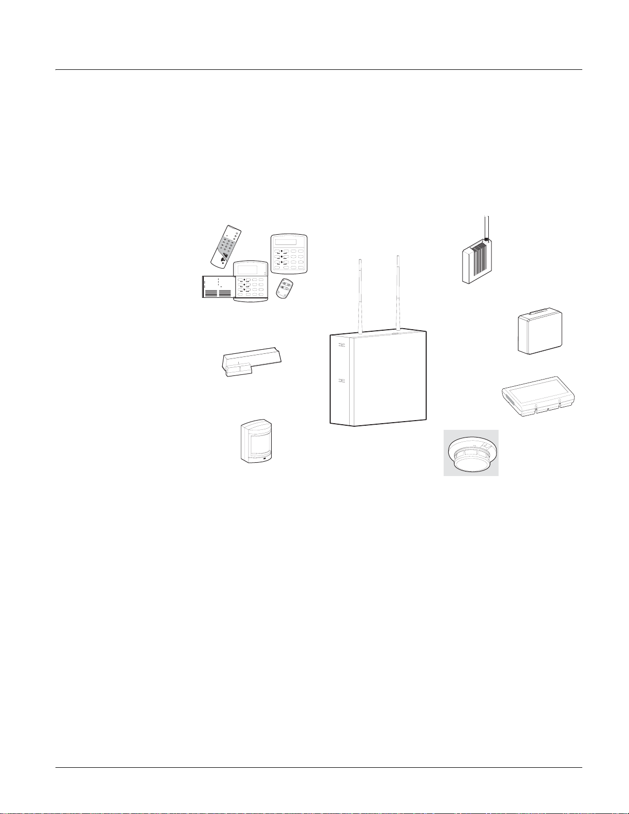
Overview
Your security system is comprised of different components. Each component plays a special role in system operation (see Figure 1):
St ay
Aw a y
Te st S ys tem W ee kly
O ff
3
A41
2
pre ss bo th
Si len t
Pa ge r
N o D e lay
5 6
B
pre ss bo th
Fe at ur es
Sy st em
M en u
8
C
7
9
pre ss bo th
St atu s
Li gh ts
By p ass
D
0 #
*
SuperBus 2000 Wireless
Gateway Module
Energy Saving Module
Qu ick G uid e
Di sar m S yst em /Ca nc el A la rm
Pre ss 1 + C OD E.
Ar m t o S TA Y
1 2 3
Ar m t o A WA Y
1 2 3
Zo ne /Se nso r N um be r
01 02 03 04 05 06 07
Clo se a ll p rote cted do ors and win dow s. Pre ss 2 + C OD E. Pre ss 4 to arm del ay d oor s ins tan tly, if d esir ed.
Clo se a ll p rote cted do ors and win dow s. Pre ss 3 + C OD E. Ex it pr emi ses thro ugh del ay d oor .
By pas s S ens ors
1
Arm sy stem to des ired lev el.
2
Pre ss B YP ASS + COD E + S enso r N o.
Tu rn CH IM E O n/O ff
1
Ma ke s ure syst em is d isarm ed .
2
Pre ss 7 + 1 to turn CH IM E o n o r of f.
Pro gr am Us er Set ting s
1
Ma ke s ure syst em is d isarm ed .
2
Pre ss A or B t o sc roll thro ugh me nus . Pre ss # to sele ct o ptio n o r ac cept ent r Pre ss to de sele ct o ptio n or can cel entr y. Pre ss 1 for OF F; p res s 2 f or O N; pre ss 0 - 9 for oth er e ntrie s.
08 09 10 11 12 13 14
Te st S yste m We ekl y
BA4
y.
C
D
Sy st em i s O K
A rm ed
Re a dy
St ay
Aw ay
Of f
1
2 3
pre ss both
Si len t
Pa ge r
No D el ay
5
6
pre ss both
Fe atu re s
Sy ste m
M en u
7
8
9
pre ss both
St atu s
Lig ht s
By pa ss
0 #
*
Touchpads
Door/Window Sensors
SuperBus 2000 Cellular
Panel
Backup Module
Motion Sensors
Environmental Detectors
Figure 1. Security System Components
Panel
The panel is at the heart of your system. It stores the intelligence to monitor all the sensors and devices in the system. The panel is the piece of equipment that initiates a call to the central sta­tion in an alarm situation. The panel circuitry is enclosed in a steel cabinet and is installed out of the way of household or workplace traffic.
Touchpads
T ouchpads allow you to communicate with your panel. You’ll use a touchpad to arm, disarm, and program your system.
Door/Window Sensors
Door and window sensors protect the perimeter of your home by alerting the panel when a door or window is opened.
Motion Sensors
Motion detectors in hallways or individual rooms detect a person moving across the field of detection.
Concord 1
Environmental Sensors
Environmental sensors such as smoke and heat detectors remain alert for the presence of fire or carbon monoxide 24 hours a day.
Phone Interface and Voice Module
Your system may contain a Phone Interface and V oice Module that allows you to use a Touchtone phone located on- or off-site as a touchpad. The module also makes it possible to get voice feed­back from speakers, guiding and informing with spoken prompts and system status reports.
Energy Saving Module
Your system may contain an optional Energy Saving Module which helps you save money by allowing your system to monitor and control the temperature of your home or business. The module can also be programmed to alert the central station in the event of furnace or AC failure.
SuperBus®2000 Cellular Backup Module
Your system may contain an optio nal SuperBus 2000 Cellular Backup Module which expands your systems reporting means with cellular telephone reporting. The module can automatically report alarms with a cellular telephone in case of inoperative landline telephone communications.
SuperBus 2000 Wireless Gateway Module
Your system may contain an optio nal SuperBus 2000 Wireless Gateway Module which allows the control and status monitoring of your system through the internet. The module will also allow you to use Event Notification by phone (voice) or email.
Communicating with the Panel
T ouchpads allow you to communicate with the panel. In turn, the system can be set up to commu­nicate with you through:
status beeps from touchpads and speakers,
•alarm sirens,
scrolling text on touchpads,
display text on fixed display touc hpads,
voice feedback over Touchtone phones or interior speakers, and
system information over pagers.
Instructing the Panel
Most of your instructions to the panel consist of this basic pattern:
Command + Access Code
Not just anyone can walk up to a touchpad and operate your security system. Before the system will process most commands, users are required to enter a pre-programmed 4-digit access code.
Keychain touchpads that are enrolled as part of the system do not require an access code, but are usually kept in an individual’s pocket or purse.
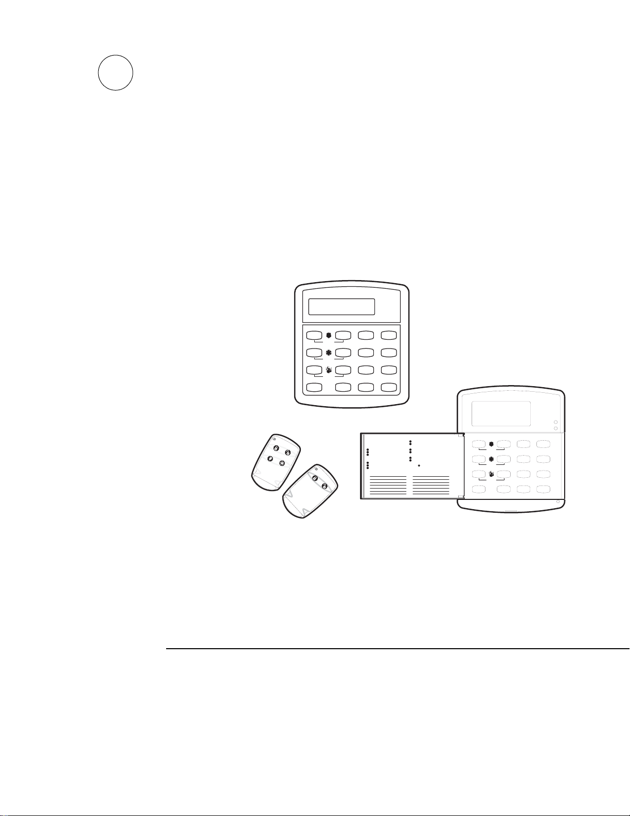
If you would rather use an actual key (see Figure 2) to arm and disarm the system, your security dealer can install a special key and keyswitch in your home.
Figure 2. Arm/Disarm Key
2
Concord
Touchpads—Your System Interface
There is a broad range of touchpads that can be used with your panel—from a single-button panic sensor which sends only panic alarms, to an alphanumeric touchpad that displays text and allows extensive user programming (see Figure 3).
S y s t e m is O K
T e s t S ys te m W e e k ly
A41
Q u ic k E x i t
A rm e d
A w a y
S t a y
O f f
2 3
p re s s b o th
N o D e la y
S i le n t
B
C
D
5
p re s s b o th
F e a tu r e s
p re s s b o th
6
S y s t e m
M en u
8
7
9
S t a t u s
L ig h ts
B y p as s
0 #
*
T es t S ys te m W e e kl y
A41
p re ss b o th
B
p re ss b o th
C
p re ss b o th
D
R e a d y
A w a y
S ta y
O f f
2 3
P a g e r
N o D e la y
S il e n t
5 6
F e at u r e s
S y s te m
M e n u
8
7
9
S ta t u s
L ig h t s
B y p a ss
0
#
*
O FF
1
S TA
Y
N O D EL A Y
2
A W AY
4
3
C HI M E
5
7
6
S TA T U S
8
S T
9
B YP A S S
0
B Y
C O MM A N D
Alphanumeric
Fixed Display
Wireless Handheld
Keychain
Panic Button
Figure 3. Touchpads
Alphanumeric Touchpads
Alphanumeric touchpads are mounted on a wall and communicate by displaying text on a two­line display.
Fixed Display Touchpads
Fixed English (display) touchpads communicate using lighted text, LEDs, and an 11 character display.
Wireless Handheld Touchpad
This touchpad is wireless and can be carried from room to room. Users can even turn on and off system controlled lights from anywhere in the home.
Keychain Touchpads
Keychain touchpads are handy for simple arming and disarming functions. They are wireless and can be carried off-site in a purse or pocket.
The installer can program specific buttons or button combinations to operate a gate or garage door, or to send a Police or Auxiliary panic alarm.
Touchtone Phones
Your system can be set up to allow system operation from a Touchtone phone on- or off-site. This includes arming and disarming, plus system features such as checking the system status and turn­ing on and off lights.
Panic Buttons
Panic button touchpads are dedicated to sending only one signal— usually a Police or Auxiliary panic alarm. These touchpads are wireless and usually kept near or on the user.
Beeps and LEDs— How Your System Talks to You
T ouchpads and interior sirens produce a variety of operating beeps to inform you of different sys­tem states and operations.
Key Beeps
A Key beep is the tone you hear when you press a button on an alphanumeric, fixed display, or handheld wireless touchpad. The sound confirms that the button was pressed adequately. Key Beeps can be turned on or off by the installer.
Status Beeps
Status beeps come from touchpads or speakers and are sounded when there is a change in the cur­rent status of the system. Status beeps are not alarms, but they do warrant your attention.
There is more than one type of Status beep:
Concord 3
Exit Delay beeps indicate that an arming command has been entered and the countdown to arming has begun.
Entry Delay beeps indicate that you’ve entered the building and the countdown to an alarm has begun. (So disarm the system as soon as you get in!)
Chime feature beeps tell you that a door was opened or closed.
Protest beeps inform you that you’re trying to arm the system while there is an open door or window.
Trouble beeps tell you that there is a problem with the system or one of its components.
Sensor test beeps are the sounds the system makes during a sensor test to indicate that a sen­sor was tested properly.
Status beeps are described in more detail throughout the manual and in the “Appendix A: User Sheets”.
LEDs
Fixed display touchpads have 2 LEDs which allow you to determine the current system status at a glance. The red LED is labeled Armed and the green LED is labeled Ready. The table below explains LED behavior.
System Statu s Red Armed LED Green Ready LED
Exit Delay Flashing Armed to Level 1-Off Off On Armed to Level 2—Stay or 3—Away On Entry Delay Flashing Off System Trouble (check system status)/Protest System OK
Off On
Note
Your system may or may not be monitored. If it is not monitored, no central sta­tion report will be made.
Notification by Pager
Your system can dial the phone numbers of five different pagers to notify pager holders of events they may want to be aware of. Some of the events include:
System disarming
System arming
Trouble conditions
Alarm conditions
For more information, see “Notification By Pager”.
What Happens in an Alarm Condition
When there is an alarm condition, four things happen all at once:
Speakers and touchpads emit emergency tones.
System lights flash.
Panel notifies the central station for help.
Pagers are notified of the event.
Fire and Smoke Alarms
If your system contains smoke and fire detectors, it monitors the premises for smoke and fire alarms 24 hours a day in all arming levels.
Most alarms can be canceled or aborted (fire alarms CANNOT be aborted) and are always reported to the central station. Since many communities charge for dispatching the fire depart­ment in error, your dealer may give you specific instructions to follow in the event of an acciden­tal smoke or fire alarm. Record these instructions in Appendix A: User Sheets under “Accidental Smoke and Fire Alarms”.
4
Concord
Note
In some cases a smoke sen­sor reset switch has been installed. If so, you’ll need to press it after Step 2.
Resetting Smoke Detectors
Most wireless smoke detectors used with this system automatically reset themselves, after detect­ing smoke. Most hardwired smoke detectors must be manually reset after detecting smoke, before they are able to detect smoke again. Check with your installer for smoke detector reset procedures for your system
T o reset wireless smoke detectors:
1. Disarm the system. The smoke detector will reset once all the smoke has cleared.
T o reset hardwired smoke detectors:
1. Disarm the system.
2. The light on the smoke detector remains lit until it is reset.
3. Disarm system again to reset hardwired detectors.
Preventing Accidental Alarms
Your security system is engineered with advanced technology that reduces the chance of an acci­dental alarm caused by a technical problem. In wireless systems, this technology prevents other devices, such as garage door openers, ham radios, television remote controls, and cellular phones, from interfering with your security system.
Most accidental alarms occur when leaving the residence after arming the system, or upon returning, before disarming the system.
If, for example, you arm the system, then run upstairs for something you forgot, the Exit Delay time may expire. Once the Exit Delay expires, opening an armed door or moving in front of a motion detector will cause an alarm.
Aborting Accidental Alarms
Your system can be set up with the opportunity to abort an accidental intrusion, Police or Auxil­iary alarm.
If the Dialer Abort feature is turned on, disarming the system within a specified time period will silence the siren and prevent the alarm from being reported to the central monitoring station (thus aborting the alarm). Your system wil l displ ay “report aborted” for a few second s, if you disarm before the alarm is reported. If you don’t disarm in time to abort the central station report, the system will automatically send an “alarm cancelled” report to the central station when the system is disarmed. Follow the procedures of your central station to prevent a false dispatch. See “Alarm Information” in Appendix A to determine if this feature is enabled for your system.
Fire alarms caused by smoke sensors, fire panic alarms, and heat sensors cannot be aborted. Dis­arming a fire alarm will silence the siren, but fire alarms are always reported. If an accidental fire alarm has sounded, follow the procedures of your central monitoring station to prevent a false dispatch.
Note
There is a communicator delay (Dialer Abort Delay) of 30 seconds programmed into this panel. The panel will delay 30 seconds before dialing the central monitoring station or a numeric pager to send reports. You can have your installer program this delay time between 15 - 45 seconds.
To cancel an alarm:
1. Press 1. Touchpads display “ENTER CODE.”
2. Enter your Access Code. OR
1. Enter your Access Code
Note
Programmed Idle Text is programmed by your installer to identify sensors, outputs, etc. For example, a sensor could be identified as “Front Door.”
Touchpads display date and time or Programmed Idle Text. The system sounds one long beep. If you’re using a Touchtone phone, see “Using a Touchtone Phone to Operate Your System”.
Guidelines for Preventing Accidental Alarms
The following guidelines will go a long way toward preventing accidental alarms.
Close doors and windows before you leave your house.
Gather your belongings, so you can exit immediately after arming the system.
Concord 5
Always enter and exit within the programmed delay times.
Make sure you leave through a door that has a delay time set for it.
Disarm your system immediately upon returning home.
Be aware of the devices in your security system and learn how each one operates.
If you have pets, ask your installer if you need pet lenses in your motion detectors.
Check the location of your smoke detectors. Smoke detectors near bathrooms and kitchens
can be tripped by steam and smoke from cooking.
T ake note of system beeps, voice announcements and indicator lights which indicate the cur-
rent system status.
Basic System Operations
This section describes:
Arming your system.
Using the chime feature.
Delay times.
Bypassing sensors.
Basic light control.
Basic output control.
Checking the system status.
For instructions on using a phone to perform any of these functions, see “Using a Touchto ne Phone to Operate Your System”.
Arming Your System
Since your security needs may vary throughout the day, this system was designed with three arm­ing levels to meet these different needs. By arming your system to a particular level, only those sensors programmed to detect in that arming level will report alarm conditions to the panel.
No matter which level your system is in, all sensors programmed to be active 24 hours a day will continue to report alarm conditions. This includes smoke detecto rs, fire sensors, panic buttons, and environmental sensors.
Keychain Touchpad Arming
To disarm your system with a keychain touchpad, press the unlock button. Your installer can set up your keychain touchp ad to arm the system in one of two ways:
1. Press the Lock button to arm the system directly to Level 3—AWAY with no Exit Delay. Using this method, you would not be able to arm to Level 2—STAY.
2. Press the Lock button to increase the arming level each time it is pressed (Level 1 to Level 2, or Level 2 to Level 3). The Exit Delay time would be applied.
Press the Lock button after arming to A WAY (Level 3) to activate the Latchkey feature (must be set up by installer). For more information, see “Latchkey Paging”.
Note
Your system may be configured to sound short beeps on exterior sirens when arming or disarming the system using a keychain or wireless touchpad. This gives confirmation that an arming change was suc­cessful even when outside. Ask your installer about this feature.
Arming Level 1—OFF
Use arming Level 1 when the system is not being used for intrusion detection. For example, on an active Saturday morning—kids playing inside and out, someone working in the garage, vari­ous house projects going on.
Even though Arming Level 1 disarms the system, your system continues to monitor fire, smoke, and panic alarms.
Here are some other situations in which you’d set the system to Level 1—OFF:
Upon entering your armed home or business. When entering the armed premises through a designated delay door, the Entry Delay time begins. Sirens and touchpads beep to remind you to disarm the system.
6
Concord
Note
If Quick Arm feature is on, an access code is not required to arm the system to Level 2— STAY.
Before opening a door or window while inside or outside the home or business. When you wake up in the morning and want to get your newspaper, you must disarm the system before opening the door to prevent an accidental alarm.
To stop sirens and cancel an alarm. When an alarm condition occurs disarming the system turns off any sirens.
T o disarm to Level 1—OFF using a touchpad:
1. Press 1. Touchpads display “ENTER CODE.”
2. Enter your Access Code. Touch pads displ ay date and time or programmed text and the sys­tem sounds one long beep.
T o disarm to Level 1—OFF using a keychain touchpad:
1. Press the Unlock button.
Arming Level 2—STAY
There are times when you want intrusion protection, but still want the freedom to move around within your house without setting off an alarm. For example, in the evening when your family is inside for the night. In this and similar situations, set your system to 2—STAY.
To arm to Level 2—STAY using a touchpad:
1. Close all protected perimeter doors and windows.
2. Press
3. Enter your Access Code. Touch pads displ a y, “Armed to STAY” and the system so unds two
4. If leaving the premises, exit through a designated delay door immediately.
1. Press the Lock button.
2 at any touchpad. Touchpads display, “ENTER CODE.”
short beeps.
To arm to Level 2—STAY using a keychain touchpad:
Note
If Quick Arm feature is on, an access code is not required to arm the system to Level 3— AWAY.
Note
Contact your installer if you want to use this feature.
Arming Level 3—AWAY
At other times, you want every sensor to be alert when the family goes on vacation, or at closing time.
In this and similar situations, set your system to 3—AWAY for maximum protection. All sensors are active—perimeter door and window sensors, and interior motion detectors.
To arm to Level 3—AWAY using a touchpad:
1. Close all perimeter doors and windows.
2. Press
3 at any touchpad. Touchpads display, “ENTER CODE.”
3. Enter your Access Code. Touchpads display, “ARMED TO AWAY” and th e system sounds
three short beeps.
4. Exit through a designated delay door immediately.
To arm to Level 3—AWAY using a keychain touchpad:
1. Press the Lock button twice to go from Level 1 to Level 3, or once to go from Level 2 to
Level 3.
Quick Arm
The Quick Arm feature lets you arm your system without using an access code. You will still need to enter an access code to disarm the system.
Quick Arm to Level 2:
1. From Level 1--Press 2.
Quick Arm to Level 3:
1. From Level 1 or 2--Press 3.
Concord 7
Note
In UL Listed systems, this feature is disabled.
Important !
If you step outside and are planning to come back in, do not close the door behind you!
Quick Exit
Your system may be set up so that when your system is armed to Level 2—STAY, you’re able to
D on any touchpad and simply walk out the door without having to disarm and rearm the
press system.
This is useful when your system is armed and you want to quickly pop outside to pick up the newspaper without disarming your system.
To use Quick Exit:
1. When the system is armed to 2—STAY, Press D at any touchpad (opening the door without
pressing
D will cause an alarm).
2. Open the door and go outside. Leave the door open if you are planning to come back in!
3. Come back in within two minutes and close the door. The system will rearm to 2—STAY.
Using the Chime Feature
Turning on the Chime feature is like having bells on every protected door and window . When this feature is on, sirens and speakers sound 2 beeps whenever anyone opens a protected door or win­dow.
The Chime feature works only in Level 1—OFF.
T o turn Chime on/off:
1. While in Level 1—OFF, from any tou chpad, Press 7 + 1. While the Chime feature is on,
touchpads display, “CHIME IS ON” or “CHIME ON.”
Chime-On-Close
The Chime-On-Close feature works like the regular Chime feature, but in addition to the double beeps heard upon opening a protected door or window, the system sounds one long beep when the door or window is closed again.
You can turn the Chime-On-Close feature on or off from the programming menus. Refer to “Using Programming Menus” for information on programming your system.
Note
Arming to Level 2 will also cause Exit Delays.
Using the Voice Chime Feature
If the installer wired speakers to the Phone Interface and Voice module outputs, you can program your system to speak the programmed sensor text whenever someone opens a protected door or window. When this feature is on, speakers announce, “Sensor name open/closed.” You can turn the Voice Chime feature on or off from the programming menus. Refer to “Using Programming Menus” for information on programming your system.
Exit and Entry Delay Times
After arming your system, you need time to exit the building so you won’t set off an alarm. Like­wise, upon returning to your home or business, you’ll need enough time to open the door and get to a touchpad to disarm the system.
The Exit Delay is a period of time long enough to let you leave through a designated delay door after arming the system.
The Entry Delay is a period of time long enough to let you open and enter through a desig­nated delay door and get to a touchpad to disarm the system.
Exit Delay Example
You’re about to go on an errand. You are inside your house and have just armed the system to Level 3—AWAY.
The interior sirens and touchpads sound three quick status beeps, telling you that the system accepted the command and has started the Exit Delay time.
During the Exit Delay time, the system sounds one short beep every 4 seconds. Exit the premises immediately.
During the last 10 seconds of the Exit Delay you’ll hear one short beep every second, warning you that the Exit Delay is about to expire. When the delay expires, you’ll hear three more quick status beeps. These beeps indicate that the Exit Delay has ended. Opening an armed door or win­dow after the Exit Delay has expired will cause an alarm (see Figure 4).
8
Concord
E x i t D e l a y
p
B E E P S
Note
Arming to Level 2 will also cause Entry Delays.
A f t e r a r m i n g , y o u ' l l h e a r 3 q u i c k b e e p s .
D u r i n g t h e E x i t D e l a y ,
y o u ' l l h e a r o n e b e e p
e v e r y f o u r s e c o n d s .
Figure 4. Exit Delay Example
w h e n t h e s y s t e m
3 q u i c k s t a t u s
b e e p s s o u n d
i s a r m e d .
Entry Delay Example
You are returning to your house that is armed to Level 3—AWAY. When you unlock and enter the designated delay door, the interior sirens and touchpads sound two short beeps every two sec­onds. This tells you that the Entry Delay time has begun and reminds you to disarm the system to avoid setting off an alarm.
During the last 10 seconds of Entry Delay, you’ll hear two beeps every second. If you hear 3 beeps every 3 seconds, an alarm has occurred while you were away.
E n t r y D e l a y
B E E P S
U p o n e n t e r i n g , a n d d u r i n g E n t r y D e l a y , y o u ' l l h e a r
s e v e ry 2 s e c o n d s .
2 b e e
Figure 5. Entry Delay Example
Your installer will work with you to decide which door(s) should be delay door(s), and determine the delay times that will work best for you and your family. Then, the installer will program the Exit and Entry Delay times into your system.
D i s a r m t h e s y s t e m b e f o r e
t h e l a s t o f 2 0 q u i c k s t a t u s b e e p s
t o a v o i d a n a c c i d e n t a l a l a r m .
Note
In UL Listed systems, this feature is disabled.
Note
The Exit Extension will work on the first re-entry only.
Extended Delay
In some situations, additional time is needed to arm or disarm the system. In these instances, the installer can program an Extended Delay time, giving you as much as 16
additional minutes to arm or disarm the system before setting off an alarm. Refer to Appendix A “Doors and Delay Times Settings” for a list of actual Exit Delay times.
Exit Extension
Your system may be set up so that the delay time is restarted if you re-open the delay door during the initial delay time.
This is useful if, after arming the system, you walk out the door, then remember something you forgot inside. You can re-enter and exit through the delay door without disarming and re-arming the system.
If your system is not using this feature, you must disarm the system when you re-enter the armed premises to avoid setting off an alarm.
No Delay—For Instant Alarm
You can choose to turn off the Entry and Exit Delays, causing the del ay doors to arm imm edi­ately. Anyone entering the house through the delay door when the system is set to No Delay would immediately cause an alarm.
No Delay is normally used:
When you’re staying at home, after you’ve armed the system.
Concord 9
Note
If Quick Arm feature is on, an access code is not required. See the “Quick Arm” section in this manual.
When you’re arming your house from the outsid e. (You must have a wireless touchpad in order to do this.)
Arming to Level 2 or 3 with No Delay, using a touchpad:
1. Close all perimeter doors and windows.
2. Enter
3. Immediately after hearing the beeps, press
2 + CODE or 3 + CODE. The system sounds two or three short beeps.
4 for No Delay. Touchpads display, “ARMED TO
STAY NO DELAY” or “ARMED TO AWAY NO DELAY,” for example.
Changing the arming level will restore delay doors to their normal Exit and Entry Delay times.
Auto STAY Arming Feature
The Auto STAY Arming feature helps cut down on false alarms in the event that you arm the sys­tem to 3—AWAY, but fail to leave during the Exit Delay time. Here’s how it works:
If you arm the system to Level 3—AWAY, and do not leave the premises within the Exit Delay time If feature turned on The system can tell that no one opened and closed a delay door
If feature turned off The system arms to Level 3—A WAY regardless of whether or not a
The dealer can turn this feature on or off for you. See Appendix A “System Features” to see if this feature is available to you.
within the delay time. It assumes that someone is still inside and the panel will arm to 2—STAY to avoid a false alarm.
delay door has been opened and closed. Your movement inside the premises could activate a motion
detector, causing an alarm.
Note
When a sensor is bypassed, you are allowing that door or window to go unprotected.
Note
You cannot bypass sensors directly using a keychain touchpad.
Arming While a Door or Window is Open
It is possible to arm your system while leaving a door or window open. This is useful if, for example, you like to sleep at night with the window open.
If the door or window has a sensor installed on it, the system must be told to ignore, or bypass, that sensor when it’s open. All other sensors will remain active.
There are two methods for bypassing a sensor:
Directly — After arming the system, bypass door/window sensors before you open them. You must know the sensor number of the door or window you wish to bypass. Your installer can include the zone number as part of the sensor text.
Indirectly — As you are arming, bypass sensors on doors and windows that are already open. This method should not be used in UL Listed installations.
Bypassing a Sensor Directly
Use this method if the system is armed and you would like to open a window without disarming. Refer to the “Appendix A: User Sheets” to determine what the sensor number is for the sensor
you wish to bypass.
To bypass sensors directly:
1. Close all doors and windows.
2. Arm your system to the desired level.
3. At any touchpad, press
4. Tou chpads disp lay, “BYPASS SENSOR _ _,” or “ENTER SN SR _ _.” Enter the desired sen­sor number.
5. Tou chpads display, “BYPASSED ZONES 01,” or “SENSOR 01 BYPASSED,” for example.
6. If the touchpad displays “INVALID,” or “FAILURE,” or if the touchpad sounds one long beep, make sure that you entered a valid sensor number. Heat and smoke sensors cannot be bypassed.
7. Bypass other sensors, if necessary, by repeating Step 3.
8. The bypassed door or window can now be opened.
# + CODE. (# is labeled Bypass)
10
T o arm (unbypass) bypassed sensors:
Concord
1. Repeat the above procedure substituting the bypassed sensor number or,
2. Close bypassed doors and/or windows and arm your system again.
Bypassing a Sensor Indirectly
Use this method if you are arming the system and would like to bypass doors and windows already open.
T o byp ass sensors indirectly:
1. Leave open only those doors and windows that are to remain open. Close all others.
2. Arm your system to the desired level. The touchpad emits protest beeps and displays “PRO­TEST,” because of the open sensor(s).
3. At any touchpad. press
# (Bypass). Touchpads with displays show, “BYPASSED ZONES
01,” or “SENSOR 01 BYPASSED,” for example.
4. The system sounds arming level beeps to indicate that the system is armed and open sensors have been successfully bypassed.
T o arm (unbypass) bypassed sensors:
1. Close bypassed doors and/or windows.
2. Arm your system again.
To bypass sensors indirectly using a keychain touchpad:
1. Press the button once to arm the system and again to bypass open sensors.
Was the Bypass Successful?
Note
For system lights to respond to basic and advanced light commands, the light switches must be turned on.
To confirm whether or not a sensor was bypassed:
1. Press the Status button on the touchpad. (* is labeled Status.) Touchpads list bypassed sensors or zones.
Basic Light Control
There are two kinds of light control:
Basic light control, offering instant light control at any touchpad, and
Advanced light control, in which lights turn on and off automatically according to specific sit­uations. (See “Advanced Light Control”).
To turn all lights on or off:
1. From any touchpad: Press 0 + 0.
From a 4-button keychain touchpad: Press the Lights button.
To turn a specific light on or off*:
1. From any touchpad: Press 0 + light number. From a 4-button keychain touchpad:
You cannot turn on a specific light using a keychain touchpad.
Refer to the User Sheets in Appendix A to determine which light number is associated with which lamp.
Basic Output Control
Panel output points control the hardware installed on your system. These outputs are usually con­figured to turn on automatically in response to certain events.
Your installer may have configured your system so that you can control some output points from your touchpad. Have the installer list and explain any outputs that are programmed for your con­trol. Use the following procedure to turn an output on or off.
T o turn the output on or off:
Concord 11
1. From any touchpad press 7 + 7 + output number. If the output was already activated, it will
shut off. If the output was off, it will activate.
Checking the Status of Your System
Checking the system status means finding out about the current condition of your system. This includes finding out if any sensors are open or currently bypassed, whether or not the AC power and backup battery are okay, the nature of the most recent alarm, and more, depending on the fea­tures in use and the equipment in your system.
Check the system status if:
Your system sounds troub le beeps (fi ve short beeps every minute).
Your touchpads display, “ALARM,” and “POLICE,” “AUXILIARY,” or “FIRE.”
Your touchpads display, “PRESS STATUS” or a blinking *. If an alarm or system trouble condition has occurred, it is displayed on a touchpad the first time
you perform a Short or Full Status check. Performing a system status check a second time dis­plays the system status including any trouble conditions.
If any alarm or system trouble is active, it continues to show up in every status check until the system is disarmed.
Short System Status
A Short Status indicates the current arming level, sensor status (whether open or bypassed), low battery, supervisory, auxiliary phone, AC power or backup battery failures.
To get a Short System Status:
1. Press *. (* is labeled Status.) The system sounds beeps according to the current arming level (one for Level 1, two for Level 2,
three for Level 3). Touchpads display and optional voice modules announce the status informa­tion, for example, “SYSTEM IS OK,” or “SENSOR 02 OPEN.”
Full System Status
A Full Status combines the Short Status information with added details about specific system features.
To get a Full System Status:
1. Press * + *. Interior sirens sound beeps according to the current arming level. T ouchpads display and optional
voice modules announce the status information, for example, “SYSTEM IS OK,” “SENSOR 03 BYPASSED,” “SYSTEM BATTERY IS OK,” “AC POWER IS OK.” If the optional Energy Saver module is installed the system will display/announce its status (on/off) and the current tem­perature (if on).
Panic Alarms Panic alarms are easily activated from any touchpad to quickly alert the central monitoring sta-
tion to a Fire, Police, or Auxiliary emergency. A panic alarm can be sent at any time, regardless of the current arming level: 1—OFF, 2—STAY, or 3—AWAY.
This system is designed to inform a central monitoring station of the nature of the emergency so the correct personnel can be dispatched immediately.
Each type of panic alarm sounds and reacts differently when activated.
Ty pe of Alarm Alarm Sound
Fire Repeating series of three beeps
Police Continuous tone
12
Auxiliary Rapid beeps
Concord
Note
Verify with your install er how your keychain touchpads are programmed. See “Appen­dix A: Keychain Touchpads” for more information.
Fire Panic Alarm
The Fire panic alarm sounds from all interior and exterior sirens. On monitored systems, the cen­tral monitoring station responds by calling the fire department.
To activate a Fire panic alarm from a touchpad:
1. Press and hold both Fire button(s) for 2 seconds.
Lighting During a Fire Panic Alarm
If your system is equipped with system lighting, all system lights will turn on and remain on dur­ing a Fire panic alarm.
Police Panic Alarm
The Police panic alarm sounds from all interior and exterior sirens, scaring off any intruder and alerting neighbors to the trouble. On monitored systems, the central monitoring station responds by calling the police.
To activate a Police panic alarm from a touchpad:
1. Press and hold the Police button(s) for 2 seconds.
To activate a Police panic alarm from a keychain touchpad:
1. Press and hold the Lock and Unlock buttons at the same time for 2 seconds.
Lighting During a Police Panic Alarm
If your system is equipped with system lighting, all system lights will flash continuously during a Police panic alarm.
Auxiliary Panic Alarm
The Auxiliary panic alarm sounds from interior sirens only. It is typically set up by your security dealer, based on your specific needs. On monitored systems, the central station responds by call­ing the service or agency you specified through your dealer, such as an ambulance service.
To activate an Auxiliary panic alarm from a touchpad:
1. Press and hold the Auxiliary button(s) for 2 seconds.
To send an Auxiliary panic alarm from a keychain touchpad:
1. Press and hold the Lights and Star buttons at the same time for 2 seconds.
Lighting During an Auxiliary Panic Alarm
If your system is equipped with system lighting, all system lights will turn on and remain on dur­ing an Auxiliary panic alarm.
Siren Time-out
If the system is not disarmed after an alarm, the sirens will continue to sound until the time-out period is reached. The time-out period can only be programmed by your installer or dealer.
Even though reaching the time-out stops the sirens, the alarm will still be in progress and will remain so until the system is manually disarmed.
Access Codes The system requires a valid access code before it will process most commands.
There is one System Master code which serves as the primary User Programming code for your system. Only a very limited number of users will need to know this code.
There are two Partition Master codes (one for each partition) which allow access to system operations in their respective partitions.
There are 230 Regular User codes (000-229) which act like keys to arm and disarm the system. If necessary, they can be assigned to neighbors, baby-sitters, or repair persons for temporary use.
Concord 13
Regular user codes can be changed in User Programming and are easily deleted from the system when no longer necessary.
Programming Access Codes
The code you use to enter User Programming determines which features such as codes and code attributes you’ll be able to change.
A user code can be given certain attributes which limit what the user can do within the system. Attributes may be changed by you, or by a dealer over the phone using downloading software.
The User Sheets in Appendix A provide a location for you to record the actual user codes and the attributes of each. If you need assistance in changing any code attributes contact your dealer.
Access Code Integrity
T o preserve the integrity of your system, keep access codes confidential and delete extra codes as soon as they are no longer needed.
We recommend that you avoid using obvious code patterns such as
System Master Code Privileges
Using the System Master code to enter User Programming allows you to:
Change the System Master code.
Change or delete the Partition Master code in the current partition.
Change or delete Regular User codes in the current partition. The default System Master code is
the new code on the User Sheets in Appendix A.
1234. It is important that you change this default and write
1234, 1111, 2222, etc.
Note
To change System and Par­tition Master codes please see Appendix C: “Using Pro­gramming Menus”.
Partition Master Code Privileges
Using the Partition Master code to enter User Programming allows you to:
Change the Partition Master code in the current partition.
Change or delete the Regular User codes in the current partition. There is not a default Partition Master code. Write partition master codes on the User Sheets in
Appendix A.
Regular User Code Privileges
You cannot enter User Programming wi th a Regular User code.
The Touchpad Tamper Feature
The installer can program your system to send a Police alarm in the case of possible touchpad tampering.
If more than 40 keys are pressed when the system asks for a code, and those keystrokes are not part of a valid access code, a siren will sound. Talk to your installer or see Appendix A “Touch­pad Information” on page 43 to see if this feature is enabled.
Changing or Erasing User Codes
A T ouchtone phone can be used to change or erase user codes, but alphanumeric or fixed display touchpads work much better because of their extensive feedback. See Appendix C for phone pro­gramming instructions.
Changing a User Code
To change or assign a user code:
1. Enter the programming menus by pressing 9 + System or Partition Master CODE.
2. Press
3. Enter the desired 4-digit code, then #.
4. Press
030 nnn 0 where nnn is the user 000 through 229.
* + 00 + # to exit the programming menus.
14
Concord
Note
The system will not accept the same code for two differ­ent users.
Erasing a User Code
When a code is deleted from the system, that code no longer acts as a key for operating the sys­tem in any manner.
T o erase a user code:
1. Enter the programming menus by pressing 9 + System or Partition Master CODE.
2. Press
3. Enter the System or Partition Master
4. Press
030 nnn 0 where nnn is user 000 through 229.
CODE, then #.
* + 00 + # to exit the programming menus.
Assigning Code Attributes
Code attributes determine what a person using their code can do. You will want certain users to have more control over the system than others. For example, you would want an adult to have more control over the system than a child. Below are code attributes that you can assign.
Assigning the Direct Bypassing Attribute
Direct Bypassing is a user code attribute that allows the user to bypass open sensors. If the user code does not have this attribute turned on, the user will not be able to bypass sensors directly.
To assign Direct Bypassing to a user:
1. Enter the programming menus by pressing 9 + System or Partition Master CODE.
2. Press
3. To turn Direct Bypassing:
on, pressoff, press
4. Press
030 nnn 1 where nnn is user 000 through 229.
2 + #.
1 + #.
* + 00 + # to exit the programming menus.
Assigning the Remote Access Attribute
Remote Access is a user code attribute that allows the user to access the security system from a telephone. If the user code does not have this attribute turned on, the user will not be able to access the system by off-premises telephones.
To assign Remote Access to a user:
1. Enter the programming menus by pressing 9 + System or Partition Master CODE.
2. Press
3. To tu rn Rem ote Access:
on, pressoff, press 1 + #.
4. Press
030 nnn 2 where nnn is user 000 through 229.
2 + #
* + 00 + # to exit the programming menus.
Assigning the Partition Jump Attribute
Partition Jump is a user code attribute that allows the user to access both partitions. If the user code does not have this attribute turned on, the user will not be able to access both partitions.
To assign Partition Jump to a user:
1. Enter the programming menus by pressing 9 + System Master CODE.
2. Press
3. To turn Partition Jump:
on, pressoff, press
4. Press
030 nnn 3 where nnn is user 000 through 229.
2 + #.
1 + #.
* + 00 + # to exit the programming menus.
Concord 15
Assigning the System Test Attribute
p
p
System Test is a user code attribute that allows the user to perform system tests. If the user code does not have this attribute turned on, the user will not be able to perform phone or sensor tests.
T o assign System Testing to a user:
1. Enter the programming menus by pressing 9 + System or Partition Master CODE.
2. Press
3. To tu rn System Testing:
on, pressoff, press
4. Press
030 nnn 4 where nnn is user 000 through 229.
2 + #.
1 + #.
* + 00 + # to exit the programming menus.
Assigning the Latchkey Report Attribute
Latchkey Report is a user code attribute that causes the panel to send a message to a pager when the user changes system arming levels. See “Latchkey Paging.
To assign Latchkey Report to a user:
1. Enter the programming menus by pressing 9 + System or Partition Master CODE.
2. Press
3. To turn Latchkey Report:
on, pressoff, press
4. Press
030 nnn 5 where nnn is user 000 through 229.
2 + #.
1 + #.
* + 00 + # to exit the programming menus.
Setting the Time and Date
Although the installer usually sets the time and date at the time of installation, the user can change it when necessary.
To set the System Time:
1. Enter the programming menus by pressing 9 + System or Partition Master CODE.
2. Press
3. Enter the correct time in 24-hour format (4 digits--see Figure 6), then press
4. Press
020.
For example, if the current time is 7:23 a.m., press
* + 00 + # to exit the programming menus.
#.
0723 + #.
2 4 - H o u r F o r m a t
0 0 : 0 0 0 1 : 0 0 0 2 : 0 0 0 3 : 0 0 0 4 : 0 0 0 5 : 0 0 0 6 : 0 0 0 7 : 0 0
M i d n i g h t
1 : 0 0 a m 2 : 0 0 a m 3 : 0 0 a m 4 : 0 0 a m 5 : 0 0 a m 6 : 0 0 a m 7 : 0 0 a m
0 8 : 0 0 0 9 : 0 0 1 0 : 0 0 1 1 : 0 0 1 2 : 0 0 1 3 : 0 0 1 4 : 0 0 1 5 : 0 0
Figure 6. 24-Hour Format
8 : 0 0 a m
9 : 0 0 a m 1 0 : 0 0 a m 1 1 : 0 0 a m
N o o n 1 : 0 0 p m 2 : 0 0 p m 3 : 0 0
1 6 : 0 0 1 7 : 0 0 1 8 : 0 0 1 9 : 0 0 2 0 : 0 0 2 1 : 0 0 2 2 : 0 0 2 3 : 5 9
m
4 : 0 0 p m 5 : 0 0 p m 6 : 0 0 p m 7 : 0 0 p m 8 : 0 0 p m
9 : 0 0 p m 1 0 : 0 0 p m 1 1 : 5 9
m
16
To set the System Date:
1. Enter the programming menus by pressing 9 + System or Partition Master CODE.
2. Press
3. Enter the current date as 6 digits (mm/dd/yy) then press
021. #.
Concord
For example, if the current date is January 15, 2000, press 011500 + #.
Adjusting System Sounds and Touchpad Brightness
Note
If Quick Arm feature is on, an access code is not required. See “Quick Arm” for more information.
Note
Arming Always Silent may have been disabled by your installer.
Note
Exit Delay is doubled when you enable Silent Arming.
4. Press
* + 00 + # to exit the programming menus.
Arming Your System Silently
Use the Silent Arming feature to arm your system without disturbing people throughout the house with arming status beeps. There are two methods for implementing Silent Arming:
Silent on Demand. (User presses
Arming Always Silent (Silent Arming feature on). Regardless of the method employed, when Silent Arming is in effect, no Exit beeps sound.
Silent Arming on Demand
Pressing 5 before arming silences arming status beeps from touchpads and interior sirens for only the current arming period.
To use Silent Arming on demand:
1. From any touchpad, press 5.
2. Within 4 seconds enter:
2 + CODE or 3 + CODE.
Arming Always Silent
Turning this feature on in User Programming means that the status beeps that come from touch­pads and interior speakers while arming will always be silent. You will not have to enter before arming, as with Silent Arming on Demand.
To enable Silent Arming:
1. Enter the programming menus by pressing 9 + System or Partition Master CODE.
2. Press
3. To turn Silent Arming:
on, pressoff, press
4. Press
041.
2 + #. No system status beeps will sound while arming.
1 + #. System status beeps will sound from touchpad while arming.
* + 00 + # to exit the programming menus.
5 before arming.)
5
Adjusting the Touchpad Beeps (Fixed Display Touchpad Only)
The frequency or pitch of chime and trouble beeps from each fixed display touchpad can be adjusted individually to a more desirable or distinct tone.
Chime and trouble beep tones sound using the default frequency during, or within 15 seconds of any button activity at that specific touchpad.
To change status tone pitc h:
1. Press and hold * + 0 until you hear a steady tone, then release the buttons.
2. Press and hold
3. Release the button when the desired pitch is heard. After about 15 seconds of no touchpad activity, the steady tone stops sounding.
1 to lower the pitch or press and hold 2 to raise the pitch.
Adjusting the System Status Voice Volume
If you have an optional voice module installed, you may want to adjust the volume at which sys­tem status messages are announced.
To change the voice volume:
1. Enter the programming menus by pressing 9 + System or Partition Master CODE.
2. Press
3. Select a volume level
4. Press * + 00 + # to exit the programming menus.
043. 17 (7 being the loudest) and press #
Concord 17
Note
Not investigated for use by UL.
Adjusting the Touchpad Display Brightness
You may want to change the bri ght ness of a touchpad display based on its location in a building or room. For example, dim the touchpad display in a bedroom or enhance a display near a win­dow.
Changing the touchpad display affects only the touchpad currently being used.
To change touchpad display brightness:
1. Enter the programming menus by pressing 9 + System or Partition Master CODE.
2. Press
3. Select a brightness level:
   
4. Press After dimming the display, pressing any button momentarily returns the display to full bright-
ness. After 15 seconds without touchpad activity, the display returns to the set dimmed level. If an alarm occurs while the display is dimmed, it automatically returns to the full brightness lev el and stays that way until you disarm your system.
042.
0 + # Off 1 + # Low 2 + # Medium 3 + # High
* + 00 + # to exit the programming menus.
Adjusting the Volume of the Wireless Siren
Your system may include a wireless siren that may be supervised or unsupervised. The system can supervise the state of the siren to make sure that it is plugged into the outlet. In addition to Police, Fire, and Auxiliary alarms, the wireless siren will sound trouble beeps in
the event of a trouble condition anywhere in the system, and emit arming status beeps during Entry and Exit Delay periods.
The wireless siren has five volume levels from 0 (silent) to 4 (loudest). All alarms sound at the loudest level, regardless of the volume setting.
Using the Energy Saver Feature
To change the volume of the wireless siren:
1. Hold down the button on the front of the siren for ten seconds until it beeps, then release it. The siren responds by beeping once, indicating it has entered change volume mode.
2. To increase the volume by one level, press the siren button for one second until it beeps. Repeat until the volume reaches the desired level.
3. After the highest level, the siren sounds one long beep, followed by 4 short beeps to signal the silent level. It then cycles through the levels again.
Use the Energy Saver feature to keep your house within a user-designated temperature range. These high and low temperature points that you set override your normal heating and air condi­tioning temperature settings. Doing so allows you to use more energy-efficient settings when away from home.
Energy Saver Example
At your touchpad, you set a high temperature point (to trigger the air conditioner) and a low temperature point (to trigger the furnace). This needs to be done only once, but can be changed easily if necessary.
Let’s say that you usually keep the temperature in your home at 68°F , but since no one will be there during the day, you turn the Energy Saver feature on. If you’ve set the low temperature point to 55°F, the furnace will keep the house heated to 55°.
You’re about to return ho me and would like the house to be heated to its normal 68°F when you arrive. If you have a Phone Interface and Voice Module installed, you can simply call home and turn the Energy Saver feature off, giving control back to the furnace thermostat (68°).
Control your air conditioning temperatures in the same manner.
18
Concord
In addition to controlling temperature, the Energy Saver feature notifies the central monitoring
S
station if your heating or air conditioning unit fails—before pipes freeze or pets are harmed by extreme heat or cold.
Setting the Energy Saver High and Low Temperature Settings
Initially, you must set the energy saver to the desired high and low temperatures. This is done only once, unless you want to change temperature settings.
The high and low settings you enter do not control heating and cooling systems, but determine the point at which the furnace or air conditioner is activated (see Figure 7).
Temperature settings can range from 45° to 90° Fahrenheit.
H i g h
S e t p o i n t
9 0 °
Note
Disarming the system will turn the Energy Saver off.
I f r o o m t e m p e r a t u r e r e a c h e s h i g h a i r c o n d i t i o n e r t u r n s o n .
I f r o o m t e m p e r a t u r e r e a c h e s l o w s e t p o i n t , f u r n a c e t u r n s o n .
L o w
e t p o i n t
4 5 °
Figure 7.Energy Saver Setpoints
s e t p o i n t ,
To set the Energy Saver temperature range from a touchpad:
1. Enter the programming menus by pressing 9 + System or Partition Master CODE.
2. Press
3. Enter the lowest allowable temperature (45–89°F) before the furnace turns on, and press
4. Press
5. Press
070.
B. Enter the highest allowable temperature (46–90°F) before the air conditioner turns
on, then press
#.
* + 00 + # to exit the programming menus.
#.
To override your normal heating or air conditioning settings, turn the Energy Saver feature on. When you are ready to return to your normal temperature control settings, turn Energy Saver off.
To turn Energy Saver on/off from any touchpad:
1. Press 7 + 2. Alphanumeric touchpads display, “ENERGY SAVER IS ON,” for example.
Notification by Pager
Your system can notify up to five different pager phone numbers to report system events. The installer can program any pager to receive pages for one or more of the following groups
High Level Reports Low Level Reports
Sensor Alarms Freeze Alarms Bypass Sensors AC Power Failure Tamper Freeze Troubles Low Battery CPU Low Battery Restorals No Activity Alarm Supervisory Auto Phone Test Phone Tests Fire Panic Trouble CPU Back in Service Receiver Failure Police Panic Phone Test Phone Failure Receiver Jam Auxiliary Panic Event Buffer Full Touchpad Low Battery
Concord 19
Touchpad Tamper Bus Failures
Opening and Closing Reports
Latchkey Reports
Notify by Exception Reports
Pager Messages
When an event is reported on a numeric pager, the following information is included:
Event Code
Sensor number or user number
Figure 8. Pager Messages
Last four digits of central station account number
Although all three types of information can be reported on your pager, your pager service deter­mines how the information will actually appear.
Event Code in Page
This part of the page let’s you know what has happened.
Code Indicates
009 A sensor has been restored to its non-alarm state 111 System has been disarmed 115 Sensor test exit 1 18 System trouble has been fixed 119 System alarm condition has been cancelled 222 System armed to Level 2—STAY 333 System armed to Level 3—AWAY 555 System phone/sensor test 888 System has a trouble condition 999 System is in alarm condition If a user arms the system to level 3 (AWAY) the pager will report that the system was armed to
level 3 (333). However, if the Auto Stay Arming feature is enabled and the user does not exit the premises, the arming level will revert to level 2 (STAY) without notifying the pager. Refer to the User Sheets in Appendix A to see whether this feature is on or off.
20
Sensor Number or User Number in Page
This part of the page let’s you know who or what is causing the event.
Code Indicates
000 System event not caused by a sensor or user 001 — 096 Sensor numbers 1 through 96 600 — 829 User codes 00 through 229 used 846 System Master code used 847 Installer code used 848 Dealer code used 850 Quick Arm used
Concord
Code Indicates
851 Keyswitch sensor used 852 System armed itself because it is being serviced or powered-up
Account Number in Page
This part of the page let’s you know where (which partition) the event is occurring.
Code Indicates
XXXX 4-digits of account number
Streamlining the Page Report
You can choose to have the four account number digits reported with every page, or to exclude them. Each partition has its own account number, so seeing the digits is useful if multiple parti­tions are reporting to one pager.
Ask your dealer or installer if you would like the Streamline feature turned on.
Event Code
Sensor number or user number
Figure 9. Pager Message with Streamline Feature On
Creating Time Schedules
Time schedules are windows of time defined by a start time, a stop time, and the days of the week these times are effective.
You can create up to 16 time schedules for setting up the following system features: light control, output control, arming, Latchkey Paging, and Notify by Exception reports.
A Touchtone phone can be used to create time schedules, but alphanumeric or fixed display touchpads work much better because of their extensive feedback. See Appendix C for phone pro­gramming instructions.
T o define a time schedule:
1. At an alphanumeric or fixed display touchpad, enter programming menus by pressing 9 + System or Partition Master CODE.
2. Press
3. Enter the start time in 24-hour format (00:00–23:59), then press
4. To di splay the current stop time for this schedule, press
5. Enter the stop time in 24-hour format, then press
6. Press
7. Enter
 
8. Press B to move to the next day of the week or press * and repeat steps 2–8 to define another
9. When finished defining time schedules, press
05 nn 0 where nn is schedule 00 through 15.
#.
The touchpad displays the new start time.
B once.
#. The touchpad displays the new stop time.
B until the touchpad displays a day of the week you wish to assign this schedule to.
2 + # to include the day in the schedule (“ON”). 1 +# to exclude the day in the schedule.
time schedule.
* + 00 + # to exit the programming menus.
Scheduling Consecutive Days
There may be instances when you’d like to schedule a feature event to start one day and stop the next day or a number of days later.
Concord 21
One Day Rollover
You can create a schedule that begins on one day, and stops the next day by using only one time schedule. (The stop time must be within 24 hours of the start time.)
Example 1 of One Day Rollover
At home you’d like the Latchkey Opening feature to be effective from 10 p.m. on Tuesday until 5 a.m. on Wednesday (see Figure 10 Example 1).
By taking advantage of One Day Rollover, one time schedule can cover both days. (That sched­ule is illustrated in Figure 10.)
Notice how the stop time is within 24 hours of the start time. The system knows to apply the stop time to the next day (5 a.m. on Wednesday).
Example 2 of One Day Rollover
Building on Example 1, let’s say that you’d like the Latchkey Opening feature to be effective between 10 p.m. and 5 a.m., Monday through Friday (ending Saturday morning).
By simply applying the start and stop times to each day, one time schedule can cover the entire week (see Figure 10 Example 2).
Multiple Day Rollover
The simplest method for defining a window of time that spans multipl e da ys is to use 99:99 to signify an open start or stop time.
Example of Multiple Day Rollover
At your business you’d like specific lights to remain lit from Friday afternoon through the week­end, until Monday morning.
In this situation, the lights need to be scheduled to roll over until they reach a recognizable stop time.
In the Figure 10 Example 3, Schedule Y is set up to begin at 4 p.m. on Friday afternoon. Since the stop time is 99:99, the lights will remain lit (roll over) until a recognizable stop time is reached.
Schedule Z is set up with an undefined start time (99:99), so if the lights were already lit, they will remain lit until the Schedule Z stop time is reached at 5 a.m.
Example 1
S c h e d u l e
S t a r t
S t o p
M o n
T u e
W e d
T h u r
F r i
S a t
S u n
P a r t .
2 2 : 0 0
0 5 : 0 0
O F F
O N
O F F
O F F
O F F
O F F
O F F
Example 2
S c h e d u l e
S t a r t
S t o p
M o n
T u e
W e d
T h u r
F r i
S a t
S u n
P a r t .
X
2 2 : 0 0
0 5 : 0 0
O N
O N
O N
O N
O N
O F F
O F F
1
X
1
Figure 10. Time Schedule Rollover Examples
S t a r t
S t o p
M o n
T u e
W e d
T h u r
F r i
S a t
S u n
P a r t .
Example 3
S c h e d u l e
Y
1 6 : 0 0
9 9 : 9 9
O F F
O F F
O F F
O F F
O N
O F F
O F F
1 1
S c h e d u l e
Z
9 9 : 9 9
0 5 : 0 0
O N
O F F
O F F
O F F
O F F
O F F
O F F
Attaching Time Schedules
For any schedule to be effective, it needs to be attached to a feature. One schedule can be attached to more than one feature event.
22
Concord
See “Advanced Light Control” for information on attaching time schedules for light control.
See “Controlling Outputs By Time Schedule” for information on attaching time schedules to outputs.
See “Schedule Arming” for information on attaching schedules to Arming.
See “Opening and Closing Reports” for information on creating opening and closing sched­ules.
See “Latchkey Paging” for information on attaching time schedules to Latchkey Paging.
See “Notify By Exception” for information on attaching time schedules to Notify by Excep­tion.
Time Schedules and Partitions
Once a schedule is attached to a feature event in one partition, that schedule becomes unavailable to the other partition. This prevents the situation where one partition changes a time schedule that inadvertently affects both partitions.
Advanced Light Control
You can control system lights from any touchpad, as discussed in “Basic Light Control”. There are other lighting options that you or your installer can set up, including:
Turning lights on and off according to a time schedule.
Turning lights on after system arming for the duration of the Exit Delay.
Turning lights on for the duration of the Entry Delay so you have enough light to see your way to the touchpad to disarm the system.
Flashing lights on and off upon successful arming and disarming.
Controlling Lights By Time Schedule
Lights can be turned on according to time schedules. If you need assistance setting up a time schedule that fits your lighting needs, see “Creating Time Schedules”.
To schedule lights:
1. At an alphanumeric or fixed display touchpad, enter the programming menus by pressing
9 + System or Partition Master CODE.
2. Press
3. Press
4. Press
5. Enter
 
6. Press
7. When you’ve finished attaching the desired time schedules, press
0640 + #. B until the touchpad displays the light number you would like to schedule. Refer to
“Appendix A: User Sheets” to determine which light number is associated with which lamp.
#. The touchpad displays the first available time schedule.
2 + # to assign the time schedule (“ON”) for this light. 1 + # to make the time schedule inactive for this light.
B to go to the next time schedule, if needed, and turn the schedule on or off for this
light.
* + 00 + # to exit the pro-
gramming menus.
Controlling Lights with Sensors
Your security system can be programmed to turn on a selected light or lights when sensors are activated. Each time the chosen sensor is activated, the attached light(s) will turn on for 5 min­utes. When 5 minutes has passed since the last activation, the light(s) will turn off. For example, if you want house lights to turn on when you open the front door, simply attach the desired lights to the front door sensor.
Note
If a light is attached to a sen­sor and a schedule, the light will only turn on and off within the scheduled start and stop times.
Concord 23
To attach lights to sensors:
1. At an alphanumeric or fixed display touchpad, enter the programming menus by pressing 9 + System or Partition Master CODE.
2. Press
080. The touchpad displays “LIGHT n TO Sn x” or “LT n SN x,” (where n is the light
number and x is the sensor number).
3. Press A or B until the light number (1–9) you would like to activate appears.
4. Enter the sensor number (1–96) you wish to activate the light and press
5. Press B to assign another light to a sensor or press * + 00 + # to exit the programming
menus.
To detach lights from sensors:
1. At an alphanumeric or fixed display touchpad, enter the programming menus by pressing 9 +
System or Partition Master
2. Press
3. The touchpad displays “LIGHT n TO Sn x” or “LT n SN x,” (where n is the light number and
4. Press
5. Enter the sensor number as 0 (no sensor) and press #.
6. Press
B until the touchpad displays “ATTACH LIGHTS TO SENSORS” or “LITE TO SN”
then press #.
x is the sensor number).
A or B until the light number (1–9) you would like to deactivate appears.
* + 00 + # to exit the programming menus.
CODE.
#.
Installer Programmable Lighting
If you would like specific lights to turn on during Entry and Exit Delay times, or if you would like a light to flash to indicate successful arming and disarming, contact your installer.
Controlling Outputs by Time Schedule
Scheduled Arming
Note
The panel cannot be dis­armed by schedules.
Outputs may be used to control devices in your home such as automatic window blinds. Outputs that your installer has enabled, can be turned on or off according to time schedules. If you need assistance setting up a time schedule that fits your needs, see “Creating Time Schedules”.
To schedule outputs :
1. At an alphanumeric or fixed display touchpad, enter the programming menus by pressing 9 +
System or Partition Master
2. Press
3. The touchpad displays “OUTPUTS.” Press
4. Press
5. Press
6. Enter
 
7. Press
8. When you’ve finished attaching the desired time schedules, press
The Scheduled Arming feature allows the panel to be armed to Level 3—AWAY according to a schedule. When an active schedule start time is reached the panel will exit User Programming, automatically bypass any open sensors, and arm to Level 3—AWAY.
The panel will not arm according to an active schedule if the start time is reached while:
T he panel is already armed to Level 3—AWAY.
T he panel is performing a phone or sensor test.
To schedule arming:
1. At an alphanumeric or fixed display touchpad, enter the programming menus by pressing 9 +
2. Press
3. The touchpad displays “AWAY.”
065 + #
B until the touchpad displays the output number you would like to schedule. Refer to
“Appendix A: User Sheets” to determine which output is associated with which output num­ber.
#. The touchpad displays the first available time schedule.
2 + # to assign the time schedule (“ON”) for this output. 1 + # to make the time schedule inactive for this output.
B to go to the next time schedule, if needed, and turn the schedule on or off for this out-
put.
gramming menus.
System or Partition Master
0660 + #.
CODE.
#.
* + 00 + # to exit the pro-
CODE.
24
Concord
4. Press #. The touchpad displays the first available time schedule as “SCHEDULE 00 OFF ,” or “SCH 00 OFF.”
5. Enter
2 + # to assign the time schedule (“ON”) to arm the panel.
1 + # to make the time schedule inactive.
6. Press
7. When you’ve finished attaching the desired time schedules, press
B to go to the next time schedule, if needed, and turn the schedule on or off for arming
to AWAY.
* + 00 + # to exit the pro-
gramming menus.
Opening and Closing Reports
Latchkey Paging
The Opening and Closing Reports feature allows pager holders and/or the central station to be notified whenever the system is armed and/or disarmed.
When Will this Feature Be Active?
The Opening and Closing Reports feature can be enabled only by the installer. There is nothing more that the user needs to program in order to receive the Opening and/or Closing pages.
If a pager holder no longer wishes to receive the reports, the pager holder needs to contact the installer to turn off this option for that pager.
Opening and Closing Reports occur without regard to any time schedule. There are no special codes that the user needs to enter in order for the page to be sent.
Who Will Be Paged?
Your system can call up to 5 different pager numbers, as well as the central station, to report an Opening and/or Closing Report.
Refer to “Appendix A: User Sheets” to see which pagers have been set up to receive a page for this feature. Contact the installer if you would like to turn Opening and Closing Reports on or off for any programmed pager or for the central station.
What Will the Pager Report?
For Opening Reports, the page reports the arming level (111 for 1—OFF) and the user. For Closing Reports, the page reports the arming level as 222 (2—STAY) or 333 (3—AWAY),
and the user that armed to that level. See “Notification By Pager” for more information.
The Latchkey Paging feature allows programmed pager holders to be notified when the system is armed and/or disarmed during specific hours or under certain conditions. For example, you could program the Latchkey feature to page you if your child doesn’t arrive home and disarm the sys­tem (using a code with the Latchkey attribute) by the programmed Latchkey time.
Page In the Event of...
You can set up the Latchkey Paging featu re to send a page in th e followin g situations:
S end a page when the system is disarmed. (Latchkey Opening)
S end a page when the system is armed. (Latchkey Closing)
Who Will Be Paged?
Your system can call up to 5 different pager numbers to report a Latchkey Opening and/or a Latchkey Closing. Latchkey pages do not report to the central station.
Refer to “Appendix A: User Sheets” to see which pagers have been set up to receive a page for this feature. Contact the installer if you would like to turn Latchkey Paging on or off for any pro­grammed pager.
Who Can Send a Page?
Only Latchkey-designated users can cause a Latchkey page to be sent. By default, this includes the first 6 Regular User codes. If you would like to include a keychain touchpad as a latchkey user, contact your installer. Any regular user code can be programm e d with this attribu te. See “Assigning Code Attributes”.
Concord 25
What Will the Pager Report?
For Latchkey Opening Reports, the page reports the arming level (111 for 1—OFF) and the user. For Latchkey Closing Reports, the page reports the arming level as 222 (2—STAY) or 333 (3—
AWAY), and the user that armed to that level. See “Notification By Pager”.
Latchkey Opening
The installer can set up Latchkey Opening for one of two types of use: Basic and Advanced.
Basic Latchkey Opening
If your system is set up for Basic Latchkey, there are two ways to send a Latchkey Opening page:
Based on Time Schedule Only
1. Assign the Latchkey Opening feature a time schedule. (This needs to be done only once.)
2. Arm the system.
3. Disarming of the system by a Latchkey-designated user within the assigned time schedule, sends an Opening page:
Based on Latchkey Modifier 6 Only
1. Arm the system, then enter 6, or press the Lock button on a keychain touchpad after arming to 3—AWAY.
2. Disarming of the system by a Latchkey-designated user sends an Opening page, regardless of assigned time schedule:
Advanced Latchkey Opening
If your system is set up for Advanced Latchkey use, there is one way to send a Latchkey Opening page:
1. Assign the Latchkey Opening feature a time schedule. (This needs to be done only once.)
2. Arm the system, then enter to 3—AWAY.
3. Disarming of the system by a Latchkey-designated user within the assigned time schedule, sends an Opening page:
In Advanced Latchkey use, paging is available only during the time schedule(s) that you assign to it.
6, or press the Lock button on a keychain touchpad after arming
26
Latchkey Closing
Latchkey Closing can be used alone, or in addition to Latchkey Opening.
1. Assign the Latchkey Closing feature a time schedule.
2. The system is disarmed.
3. Arming of the system by a Latchkey-designated user within the assigned time, schedule sends a Closing page:
A Touchtone phone can be used to set up Latchkey paging, but touchpads work much better because of their extensive feedback. See “Appendix C” for touchpad and phone programming instructions.
Assigning a Time Schedule to Latchkey Paging
Follow these steps to attach a time schedule to Latchkey Opening and/or Latchkey Closing. If you need assistance setting up a time schedule that fits your needs, see “Creating Time Sched­ules”.
Scheduling Latchkey Opening and/or Closing:
1. At an alphanumeric or fixed display touchpad, enter the programming menus by pressing
9 + System or Partition Master CODE.
2. Press
3. To schedu le:
Latchkey Opening, press
0600 + #.
# when the touchpad displays “LATCHKEY OPENING” or
Concord
Note
6 must be pressed within 5
seconds of arming. If Quick Arm feature is on, an access code is not required. See “Quick Arm” for more infor­mation.
“LATCH OPEN.”
Or, press
then press If you want a page to be sent every time Latchkey-designated users codes arm or disarm the
system, apply the same time schedules under Latchkey Opening and Latchkey Closing.
4. The touchpad displays the first available time schedule.
5. Enter
2 + # to assign the time schedule to the event.
1 + # to make the time schedule inactive for the event.
6. Press
7. Press
8. When you’ve finished attaching the desired time schedules, press gramming menus.
B until the touchpad displays “LATCHKEY CLOSING” or “LATCH CLOSE,”
#.
# to secure your choice. B to go to the next schedule and repeat step 5.
* + 00 + # to exit the pro-
Applying the Latchkey Modifier
The Latchkey modifier (6) is pressed after the arming keypress sequence.
Applying the Latchkey modifier from a touchpad:
1. At any touchpad, press 2 3 + CODE + 6. The touchpad displays, “LATCHKEY PAGER ON” or “PAGER ON.”
To apply the Latchkey modifier using a keychain touchpad:
Press the Lock button when the system is armed to level 3—AWAY.
Notify by Exception
The Notify by Exception feature allows programmed pager holders and/or the central station to be notified when arming or disarming occurs outside of specified time schedules.
Here are two specific examples of how the Notify by Exception feature might be used in a busi­ness setting:
Every morning you’d like to be notified if your business is disarmed after its normal opening time.
Every evening you’d like to be notified if your business is armed before its normal closing time.
Page In the Event of...
You can set up the Notify by Exception feature to page in the following instances:
Send a page if the system is disarmed before the Opening time schedule begins or after the Opening time schedule has ended. (Exception Opening)
Send a page if the system is armed before the Closing time schedule begins or after the Clos­ing time schedule has ended. (Exception Closing)
Who Will Be Paged?
Your system can call up to 5 different pager numbers to report an Open Exception and/or Closed Exception. You can request that the central station receive these two reports as well.
Refer to “Appendix A: User Sheets” to see which pagers have been set up to receive a page for this feature. Contact the installer if you would like to turn the Notify by Exception feature on or off for any programmed pager or the central station.
Who Can Send a Page?
All user codes and keychain touchpads will send a page if used while Notify by Exception fea­ture is in effect.
Concord 27
What Will the Pager Report?
Exception Opening Reports report the arming level as 111 (1—OFF) and the user that disarmed the system.
Exception Closing Reports report the arming level as 222 (2—STAY) or 333 (3—AWAY), and the user that armed to that level. See “Notification By Pager”.
When Will this Feature Be Active?
The most typical setup of this feature makes use of both Exception Opening and Exception Clos­ing. (It is possible to use only Exception Opening or only Exception Closing, however.)
Assigning a Time Schedule to Exception Opening and Closing
Follow these steps to define Opening and Closing schedules for Exception paging. If you need assistance setting up a time schedule that fits your needs, see “Creating Time Schedules”.
A Touchtone phone can be used to set up Notify by Exception, but touchpads work much better because of their extensive feedback. See “Appendix C” for touchpad and phone programming instructions.
Scheduling Exception Opening and/or Closing:
1. At an alphanumeric or fixed display touchpad, enter the programming menus by pressing 9 +
System or Partition Master
2. Press
3. To schedu le:
Exception Opening, press
Exception Closing, press
4. The touchpad displays the first available time schedule.
5. Enter
 
6. Press
7. Press
8. When you’ve finished attaching the desired time schedules, press
0620 + #.
“ECEPT OPEN,” then press #.
“ECEPT CLOSE,” then press
2 + # to assign the time schedule to the event. 1 + # to make the time schedule inactive for the event.
# to secure your choice. B to go to the next schedule and repeat step 5.
gramming menus.
CODE.
# when the touchpad displays “EXCEPTION OPENING” or
B until the touchpad displays “EXCEPTION CLOSING” or
#.
* + 00 + # to exit the pro-
The No Activity Feature
Using the Panel Download Feature
28
The system can monitor the activity in your home and automatically call for help if normal activ­ities are not detected within a defined period of time.
For example, if someone falls and can’t move, the system will detect that normal activities, such as placing outgoing calls or opening doors and windows, have not occurred for a predetermined No Activity time.
The system sounds a low-volume auxiliary alarm to let you know there may be a problem. If all is well, you can stop the siren by disarming your system. If no one disarms the system for 5 min­utes, your system calls the central monitoring station. The central monitoring station will respond in accordance to the guidelines set forth in your monitoring agreement.
Refer to “Appendix A: User Sheets” to see if the No Activity feature is currently available to you and the duration of the No Activity setting. If the feature is not currently available to you and you wish to have it, contact your installer.
To download to the panel is to replace the old information in it with new information. Download­ing is performed only by your dealer using software specifically designed for this panel.
Turning the Download feature on allows the dealer remote access to your panel in order to:
Update your account.
B ack up dat a from you r panel.
Allow your dealer to quickly implement requested programming changes.
Concord
Note
Before allowing any down­load sessions, the system must be disarmed to level 1—OFF.
To enable/disable the Panel Download setting:
1. Enter the programming menus by pressing 9 + System or Partition Master CODE.
2. Press
3. To turn Downloading:
on, press off, press
4. Press
040. 2 + #. The dealer will be able to access your system remotely if necessary.
1 + #. The dealer will not be able to access your system remotely.
* + 00 + # to exit the programming menus.
Using a Partitioned System
The panel can be set up by your installer to operate as a two-partitioned system. A partitioned system would be useful in a strip mall, or residential duplex, where two stores or
households could share one system.
Global Settings
Global system settings affect both partitions. Most are set by the installer. Global settings that are programmed by the user include:
T he time and date.
T he System Master code.
Partition-Specific Settings
Partition-specific settings affect only one partition. User-programmable, partition-specific set­tings include:
Partition Master codes (1 per partition for a total of 2).
A pool of 230 Regular User codes for use by one or the other partition. (Partition 1 Regular User codes + Partition 2 Regular User codes = 230 Regular User codes)
A pool of 16 time schedules available to one or the other partition. (Partition 1 time schedules + Partition 2 times schedules = 16 time schedules)
9 Advanced Light Control setups available to each partition.
The Latchkey feature.
The Notify by Exception feature.
The Silent Arming option.
T he Scheduled Arming feature.
S peaker volume settings.
T he Energy Saver feature and its high and low setpoints.
To program any of these features for another partition, you must enter the User Programming menu from a touchpad in that partition, or jump into that partition, then enter the User Program­ming menu.
Jumping Partitions
Note
If your system uses just one partition, skip this section.
Concord 29
An alternative to jumping partitions is to arm, disarm, or program from a hardwire touchpad belonging to the other partition.
The ability to jump to another partition is an attribute assigned to each user code see “Assigning Code Attributes”. By default, the System Master is the only code that can jump partitions. Refer to the “Appendix A: User Sheets” to see if any other access codes have the ability to jump parti­tions.
T o jump partitions:
1. From any hardwired touchpad, press 8 + CODE + 6. Touchpads display, “ENTER PARTITION” or “ENTER CMD.”
2. Press
1 if you want to change to Partition 1 or 2 if you want to change to Partition 2.
The touchpad sounds one short beep if the jump was successful. One long beep means the jump was not successful. Alphanumeric touchpads display the text in the newly entered parti­tion.
3. Proceed to arm, disarm, or program as needed. The partition assignment reverts back if no keys are entered for 10 seconds.
Arming and Disarming the Other Partition
Once in the other partition, you need to use a code that is valid in that partition to arm, disarm or program that partition.
Programming the Other Partition
Only one partition can be programmed at a time. When one partition is using the programming menu, touchpads in the other partition are locked out from any programming activity. Arming and disarming can continue, however.
Some partition-specific settings share resources, such as access codes and time schedules. For example, if Partition 1 uses Regular User numbers 00 through 20, Partition 2 will not be able to see or use those user numbers. The first Regular User number available to Partition 2 would be
21.
The allocation of time schedules works in much the same manner. There are 16 schedules that can be used by either partition, but as soon as Partition 1 attaches a schedule to any event, that schedule cannot be used by Partition 2, and vice versa.
System Information
Viewing Event Buffer
There is information about your system that is useful to know . This includes the factory code, the system number, and the system level.
After identifying the information for your system, make a note of it in the “Appendix A: User Sheets”.
To identify system information:
1. Enter the programming menus by pressing 9 + System or Partition Master CODE.
2. Press
 The first information displayed is the factory code. For example, “F nnn – nnnn,” or “FAC-
Press
Press
3. Press
Your have the option to view the event history for each partition of yo ur system. Events include all system activity that has occurred on your system. These events include arming, disarming, tampers, programming entries, just to name a few.
010.
TORY CODE nnn * nnnn.”
B to display the system number. For example, “N – nnnnnnn,” or “SYSTEM NUM-
BER ] nnnnnnn.”
B to display the system level. For example, “L nnnn,” or “SYSTEM LEVEL nnnn.” * + 00 + # to exit the programming menus.
Overview
The installer , dealer and system master codes can view all events from any partition. The par­tition masters can only view global system events and events related to their respective parti­tion. Regular user codes cannot view event history.
All partitions can view event history simultaneously, but only one touchpad at a time can view the history in each partition. While the event history is being viewed, all other control­ling sources are disabled (except for panic alarm buttons) and non-viewing touchpads will display “VIEWING EVENT BUFFER”.
30
To view event history:
1. The current partition must be armed to level 1 or 2.
2. At an alphanumeric touchpad, press 8 + System or Partition Master CODE + 8.
T he touchpad displays “VIEWING EVENT BUFFER” followed by:
Event Description
Date/Time OR Details (user, source, zone, etc.)
Concord
T he most recent event appears first.
Scroll through the events by pressing the A (back) and B (forward) keys.
The C key is used to toggle the second line display between Date/Time and Details.
Press the * key to exit Viewing Event History.
The Viewing Event History mode will exit automatically after one minute of inactivity OR
when an alarm occurs.
The following table contains a comprehensive list of displayed events and their associated details (partition, current arming level, zone, bus unit number, source and user). If details are displayed for an event an X will appear in the table.
Partition will display P1 or P2, depending on the partition of the event.
C urrent Arm ing Level will di splay Lx, where x is the current arming level of the event .
Zone will display Zx, where x is the zone of the event.
B us Uni t Num ber will display Bx, where x is the unit number of the Bus device.
Source will display Sxxx, where xxx is the source number (see table on source numbers for more information) in the event.
User will display Uxxx, where xxx is user number (see table on user numbers for more infor­mation) in the event.
Event Display Partition
AC Power Failure AC POWER FAILURE X AC Power Restoral AC POWER RESTORAL X Antenna Tamper RCVR TAMPER X X
Arming Level Change Auto Force Arm AUTO FORCE ARM X X X Auto Phone Test AUTO PHONE TEST X Auxiliary Panic AUXILIARY PANIC X X Auxiliary Panic Cancelled AUXLRY CANCELLED X X Bus Cover Tamper BUS TAMPER X X Bus Failure BUS FAILURE X X Closing Report CLOSING REPORT X X X X CPU Back In Service BACK IN SERVICE X X CPU Battery Restoral BATTERY RESTORED X CPU Low Battery CPU LOW BATTERY X Daylight Savings Time Adjust DAYLIGHT SAVINGS Download Session Entry DOWNLOAD ENTRY Download Session Exit DOWNLOAD EXIT Duress Alarm DURESS X X Event Buffer Viewing Entry EVENT VIEW ENTRY X X X Event Buffer Viewing Exit EVENT VIEW EXIT X X X Fire Panic FIRE PANIC X X Fire Panic Cancelled FIRE CANCELLED X X Force Arm FORCE ARM X X X Installer Programming Entry INST PROG ENTRY X X X Installer Programming Exit INST PROG EXIT X X X
3
ARM LEVEL CHANGE X X X
Current
Arming
Level
Zone
Bus Unit
Number
Source 1User
2
Concord 31
Event Display Partition
Current Arming
Level
Zone
Bus Unit
Number
Source 1User
Lost Event LOST EVENT Main Unit Tamper MAIN UNIT TAMPER X Memory Clear MEMORY CLEAR Memory Failure MEMORY FAILURE No Activity Alarm ACTIVITY ALARM X No Activity Cancelled ACTIVITY CANCEL X X Opening Report OPENING REPORT X X X X Phone Failure PHONE FAILURE X Phone Line Test Fa ilure PHONE LINE FAIL Phone Line Test Restoral PH LINE RESTORED Phone Test PHONE TEST X X X Police Panic POLICE PANIC X X Police Panic Cancelled CANCELLED X X Receiver Failure RECEIVER FAILURE X X Receiver Jam RECEIVER JAM X X Recent Closing RECENT CLOSING X X X Remote Access Lockout REMOTE LOCKOUT Repeater Jam REPEATER JAM X X Repeater Jam Restoral JAM RESTORED X X Siren Trouble SIREN TROUBLE Swinger Shutdown SWINGER X Time Change TIME CHANGE Touchpad Tamper TOUCHPAD TAMPER X X Touchpad Tamper Cancelled TP TAMPER CANCEL X X Two Trip Error TWO TRIP ERROR X X User Programming Entry USER PROG ENTRY X X X User Programming Exit USER PROG EXIT X X X Zone Alarm ALARM X X Zone Alarm Cancel ALARM CANCELLED X X Zone Alarm Restoral ZONE RESOTRED X X Zone Battery Restoral BATTERY REST ORED X X Zone Bypass BYPASSED X X X Zone Low Battery LOW BATTERY X X Zone Supervisory SUPERVISORY X X Zone Tamper TAMPER X X Zone Trouble TROUBLE X X Zone Trouble Restoral TROUBLE RESTORED X X Zone Unbypass UNBYPASSED X X X
1
Source information will only be shown if the information was available when the event was buffered.
2
User information will only be shown if the information was available when the event was buffered.
3
Line two of the display also contains “P-C” where P is the previous arming level and C is the current arming level.
2
32
User information is shown in the following table.
Concord
Detail Screen Display User
U001 - U096 Wireless Touchpad or Keyfob U600 - U829 Regular User Codes 000 - 229 U830 Partition 1 Master Code U831 Partition 2 Master Code U838 Partition 1 Duress Code U839 Partition 2 Duress Code U846 System Master Code U847 Installer Code U848 Dealer Code U849 AVM Code U850 Quick Arming U851 Keyswitch Arming U852 System
Source information is shown in the following table.
Detail Screen Display Source
S00 Premise Phone S01 Phone During Conversation S02 Remote Phone S06 Auto Stay Arming S08 Keyswitch Arming Zone S09 System S1xx (xx = Zone Number) Keychain T ouchpad S1xx (xx = Zone Number) Wireless T ouchpad S3xx (xx = Bus Unit Number) Alphanumeric Touchpad S6xx (xx = Bus Unit Number) Fixed Display Touchpad
Using a Touchtone Phone to Operate Your
Your system may be equipped with a Phone Interface and Voice Module that allows system oper­ation from a Touchtone phone on or off the premises.
The module contains a digital-voice chip, enabling programmed text to be spoken through the phone and/or broadcast through interior speakers. Except for custom words, the voice will speak the text that appears on alphanumeric touchpads in the system.
System
Phone Command Prefix
What distinguishes a call to the panel from any other out-going or incoming call is the use of the Phone Command Prefix:
In the case of on-site operation, if the Phone Command Prefix is dialed first (within 5 seconds of picking up the phone), the panel pricks up its ears and waits for a valid access code or com­mand.
If the system is being accessed remotely, the Phone Command Prefix is used in conjunction with the access code.
The prefix is usually use
* as the first key you press instead of #.
Concord 33
#, but can be changed to * by the installer. If your prefix has been changed,
Accessing the System from Off-site
To access the system from off-site, the system needs to recognize two things about the call:
T he panel needs to recognize that it should answer the phone.
The panel needs to recognize that the code entered has the authority to operate the system from off-site.
When using a cellular phone to operate the system, follow the off-site operating instructions.
How the Panel Answers the Phone
When you call the panel, it needs to recognize that it should answer the incoming call. This is accomplished by one of two methods:
Ring-Hang-Ring method
Twelve-Ring method
Ring-Hang-Ring Method
You can use this method if there is no chance that an answering machine or person will pick up the call on the first ring.
1. Call the panel. (In most cases this is the same number as the regular phone.)
2. Let the phone ring once, then hang up.
3. Wait between 8 and 30 second s, then call the panel again. This time the panel will answer (“System hello,”) on the first ring.
4. Enter
5. Enter your access
6. You hear a short status message, such as, “System is OK.”
7. Proceed with system commands.
# (your designated Phone Command Prefix).
CODE.
Twelve-Ring
You can use this method if there is no chance that an answering machine or person will pick up the call before the twelfth ring.
1. Call the panel and let the phone ring. The panel will answer “System hello” after the twelfth ring.
2. Enter
3. Enter your access
4. You hear a short status message, such as, “System is OK.”
5. Proceed with system commands.
# (your designated Phone Command Prefix).
CODE.
Codes with Remote Access Capability
The ability to access the system from off-site is a code attribute see “Assigning Code Attributes”. Check the User Sheets in Appendix A to see which access codes have the ability to operate the
system from off-site.
Touchtone Phone System Operation
Phone operation of your system involves 2 steps:
Step 1. Use a Touchtone phone to access the system.
Local Phone Access Pick up the phone. Within 5 seconds of picking up the phone receiver,
Remote Phone Access Use the Ring-Hang-Ring or the Twelve-Ring method to get the system
enter the command prefix.
to answer the call. Then enter
# (or designated phone prefix) + CODE
34
Concord
Step 2. Enter the command.
Disarm the system Arm to Level 2* Arm to Level 3* Send a Police panic alarm
Arm system with No Delay*
# + 1 + CODE # + 2 + CODE # + 3 + CODE * + * + * + * + * + *
(Available from on-site only.)
# + 2 + CODE + 4 or # + 3 + CODE + 4
Arm to enable Latchkey*
# + 2 + CODE + 6 or # + 3 + CODE + 6
Arm system with exit lights off*
# + 2 + CODE + 0 or # + 3 + CODE + 0
Bypass a sensor
Arm silently*
Indirectly: Arm system + Directly: # + # + CODE + Sensor Number
# + 5 + 2 + CODE or
# + #
# + 5 + 3 + CODE
Turn all lights on/off Turn specific lights on/off Cancel an accidental alarm Check the system status
# + 0 + 0 # + 0 + Light number (1–9) # + 1 + CODE # + for short status
# + ** for full status
Turn Chime on/off Turn Energy Saver on/off Disable local phone access
Check alarm memory Activate Outputs
* If Quick Arm feature is on, access code is not required. See page 6 for more information.
# + 7 + 1 # + 7 + 2 # + 7 + 3 (on-site only) or
Wait 5 seconds after picking up a local phone.
# + 7 + 6 # + 7 + 7 + Output number (1–6)
Sending a Police Panic Alarm
Your system can be set up so that you can send a Police panic alarm from a Touchtone phone. If your system is set up to send a Police panic alarm:
•Use the
D o no t wait more than two seconds between key presses. Continue pressing hear the system voice interrupt with a system status.
Police panic alarms can be activated from a To uchtone phone on the premises only. The alarm cannot be activated from an off-site phone
*, regardless of your phone command key.
* even if you
Phone Questions?
What if someone calls while I’m operating the panel?
If the phone rings while you’re using it to operate the system, you’ll hear one long beep for each ring from interior speakers and phones. Y ou can answer the call by simply hanging up on the sys­tem, then answering the call as you normally would.
You’ll have to initiate anoth er session to resume operation.
Can I control the system while I’m talking on the phone?
No.
Concord 35
How do I perform other phone operations without commanding my security system?
You can use your phone for transactions such as banking from home by temporarily disengaging phone control to your security system. The following procedure will work for one call at a time.
To disengage local phone control:
1. Enter # + 7 + 3. The system responds by returning a dial tone.
2. Pick up the phone receiver and wait 5 seconds before dialing any numbers. After the 5 second period, the system disables local phone control and ignores phone commands.
Testing the System
Note
Make sure system is dis­armed when performing sen­sor tests.
The system contains a test mode that allows you to test sensors and panic signals without creating false alarms in monitored systems. Please follow the instructions in this section carefully.
Automatic Test Features
Your security system conducts routine tests, checking for problems like power failures, low bat­teries, sensors that aren’t working, and communication trouble with the central monitoring sta­tion.
When your system detects a problem, trouble beeps sound to alert you. See “Troubleshooting” for an explanation of the causes of trouble beeps and what you can do to fix the problem.
Manual Tests
The automatic tests your system performs provide continuing reassurance that it is working prop­erly. There are also weekly system tests you can do yourself as an added safeguard. Taking time to do these tests will familiarize you with your system and alert you to anything unusual, such as cut phone lines or sensors that have been tampered with.
Sensor Test
This test verifies that the sensors in your system are operating correctly. The ability to conduct a sensor test is a code attribute.
Check the User Sheets in Appendix A to see which access codes have the ability to conduct a sensor test. See “Assigning Code Attributes” or talk to your installer for information on changing code attributes.
Sensor test reports are sent to the central station at the beginning and end of system tests.
T o enter Test Mode:
1. Press 8 + CODE + 3. Touchpads display, “Press Status. System Armed to Sensor Test,” or “] SENSOR TEST nn
MINUTES LEFT .” When less than 5 minutes remain in Test Mode time, the system sounds a short beep every 60 seconds. System test
2. Follow the test procedure for each device as listed in the table below.
Device Test Procedure Touchpad Result(s)
Touchpad Send a:
Police panic alarm, Fire panic alarm, and Auxiliary panic alarm.
Wireless Touchpad Press the Bypass key.
36
Touchpad Panic POLICE OK
Touchpad Panic FIRE OK
Touchpad Panic AUXILIARY OK
POLICE PANIC OK
•FIRE PANIC OK
AUXILIARY PANIC OK
Zones nn OK
TOUCHPAD nn OK
Concord
Device Test Procedure Touchpad Result(s)
Keychain Touchpad
Panic button Press and hold the appropriate panic button(s) for 3
Door/window sensor Open the secured door or window.
Press and hold the Lock and Unlock buttons simultaneously for 3 seconds.
Press and hold the Star and Light buttons simultaneously for 3 seconds.
full seconds.
Zones nn OK
TOUCHPAD nn OK
Touchpad Panic AUXILIARY OK
AUXILIARY PANIC OK
Zones nn OK
•SENSOR nn OK
Zones nn OK
•SENSOR nn OK
Smoke detector Press and hold the test button until the system sounds
Motion detector Avoid the motion detector view for 5 minutes, then
Rate-of-Rise Heat Detec­tor (Not UL investigated)
Shock sensor (Not UL investigated)
Phone Interface and Voice Mo du l e
Supervised wireless siren Unplug the siren and check the touchpad display.
Glass guard sensor (Not UL investigated)
Freeze sensor (Not UL investigated)
transmission beeps.
enter its view. Rub your hands together until warm, then place one
hand on the detector for 30 seconds. Tap the glass twice, away from the sensor. Wait at
least 30 seconds before testing again. Activate a Police panic by accessing the system using
the phone and pressing
Plug the siren in. Tap the glass 3 or 4 inches from the sensor.
Apply an ice cube wrapped in plastic to the sensor. Do not allow the sensor to get wet.
* + * + * + * + * + *.
If you need more time to complete testing, restart the timer by pressing
C heck to see that all sensors have been tested by pressing
*. Touchpads display a list of untested sensors.
Zones nn OK
•SENSOR nn OK
Zones nn OK
•SENSOR nn OK
Zones nn OK
•SENSOR nn OK
Zones nn OK
•SENSOR nn OK
POLICE PANIC OK
•SENSOR nn OK
Zones nn OK
Zones nn OK
•SENSOR nn OK
Zones nn OK
•SENSOR nn OK
8 + CODE + 3.
You will know that you have finished testing when touchpads display, “SENSOR TEST OK” or “ZONES ALL TESTED.”
3. Disarm to Level 1 to exit Test Mode.
Phone Communication Test
The purpose of this weekly test is to verify that the connection between the central monitoring station and your system are working properly.
Most phone tests take only a few minutes, however, your system will try for up to 15 minutes to establish a connection.
To perform a phone communication test:
1. Disarm the system.
2. Press touchpads display, “]PHONE TEST” or “System Armed to PHONE TEST.”
3. If the phone test is successful: the optional voice module will announce, “Phone Test OK.”
Within a few minutes, the display should return to the Level 1 display. If it does not return in three minutes, note how long before the Level 1 display returns and contact the installer.
After the test has started, the arming level can be changed to 1—Off, then to 2—Stay or 3— AWAY, if you wish.
Concord 37
8 + System or Partition Master CODE + 2.
Testing Sirens
The purpose of this weekly test is to verify that the panel is activating sirens with the appropriate warning sounds.
To perform an alarm siren warning sound test:
1. Contact the central monitoring station to inform them that you will be activating alarms and
they should not dispatch authorities.
2. Activate alarms of each type (fire, police, auxiliary), one at a time.
3. Listen for the appropriate siren sound when each alarm is activated (see the “Alarm Sounds and Status Beeps” table on page 49).
4. Contact the central monitoring station to inform them that you are finished activating alarms.
Troubleshooting Your security system uses a variety of different alarm sirens, status beeps, voice messages and
trouble beeps to communicate with you. The next few pages describe the different sounds and what they mean. Try to familiarize yourself with the differences. You will hear sounds each time you tell your security system to do something, like arm or disarm. Some sounds you will hear only when there is a problem with the system, like a low battery. There are also sounds you will only hear in an emergency. Getting to know your system sounds allows you to react quickly and appropriately to the messages you hear.
Trouble Beeps and Trouble Messages
When your system detects a problem, it lets you know by sounding trouble beeps from system touchpads and sirens, and by displaying trouble signals as messages on touchpads.
Trouble beeps are a series of five short beeps once a minute. The table on the next page lists the causes of trouble beeps, the visual display you can expect to
see, and possible solutions for the trouble condition.
Silencing Trouble Beeps
If possible, correct the situation which is causing the trouble beeps. If this is not possible, call for service. If the problem is not corrected, trouble beeps and messages start again 4 or 10 hours later.
Your security system also has a feature that will prevent trouble beeps from starting during nor­mal sleeping hours. This “sleep time” period is normally set from 10 pm to 8 am. Contact your installer if you wish to verify or change this setting.
T o silence trouble beeps:
1. Perform a system status check by pressing * on a touchpad,
2. Change the arming level.
The table on the next page describes the conditions under which trouble beeps occur and when they begin. (These sounds are heard from interior sirens and touchpads if available.)
38
Common Questions and Answers
Q.I can’t arm my system.
A.Try the following:
If arming to Level 2—STAY or Level 3—AWAY, make sure all monitored perimeter doors and windows are closed.
Press
Call the installer.
Q.I cannot bypass a sensor: my alphanumeric touchpad displays “INVALID” and my fixed dis­play touchpad sounds a single, long beep.
A.Possible explanations include:
T he sensor you’re trying to bypass may not be active in the current arming level. For exam-
You may be trying to bypass a 24-hour sensor that cannot be bypassed, such as a smoke
* for a system status and for clues to the problem.
ple, an interior motion detector will not be active in Level 2—STAY.
detector.
Concord
Your access code has not been assigned the direct bypassing attribute. See “Assigning the Direct Bypassing Attribute”.
Q.I can’t arm my system to Level 3—AWAY.
A.If a delay door is open while you’re trying to arm the system to Level 3, the system will arm to Level 2 instead. Close the delay door, arm the system to Level 3, then exit through a delay door.
Phone Issues
Q.How do I disable my system long enough to retrieve messages fr om work or to do banking over the phone?
A.Solutions include:
Disengage the security system from local phone control by entering
# + 7 + 3. The system
responds by returning a dial tone.
Pick up the phone receiver and wait 5 seconds before dialing any numbers. After the 5 second period, the system disables local phone control and ignores phone commands.
Siren Issues
Q.When testing my wireless siren, unplugging it does not cause any test results. A.The test procedure described in “Testing the System” applies only if the siren is supervised. If
the system does not acknowledge the sensor test with two beeps, or the alphanumeric touchpad does not display “SENSOR nn OK,” your wireless siren may be unsupervised. Check the User Sheets in Appendix A or ask your installer.
Lighting Issues
Q.My lights don’t come on automati cally as they’ve been programmed to do.
A.Try the following:
Does the lamp have a working bulb?
Is the lamp plugged in at a working outlet that is not controlled by a light switch?
Is the lam p plugged in to a lamp module?
M ake sure that you’ve attached the correct time schedule as described in “Advanced Light Control”.
Check to see that you’ve set up the time schedule correctly as described in “Creating Time Schedules”.
Check the User Sheets in Appendix A to see in which partition the light is set up to be active.
Touchpad/Voice Feedback
After Pressing
AC POWER FAILURE The panel power transformer may be unplugged or there may be an AC power outage. If
LOW BATT The power in the emergency backup battery is low and must be recharged or replaced. If
SENSOR SUPERVISORY There is a problem with how the sensor is communicating with the panel.
SENSOR TROUBLE A sensor may have an internal problem or a fire/smoke sensor may not have properly reset
Concord 39
* Key
the transformer is plugged in, check the circuit breaker or fuse that controls that outlet. The backup battery will take over, but if AC power is not restored within 15 minutes, the system will alert you and the central monitoring station (if your system is monitored). It reports again when power is restored.
AC power is out, the security system may shut down once the battery is below the operat­ing level. When AC power is restored, the panel will recharge the battery. If the trouble condition exists more than 24 hours after AC power is restored, call your security dealer for service.
1. Test the sensor in Test Mode.
2. If testing the sensor does not clear the trouble condition, call your security dealer for service.
after activation, or the sensing chamber may be dirty or partially obstructed.
1. Test the sensor in Test Mode.
2. If testing the sensor does not clear the trouble condition, call your security dealer for service.
Trouble Condition
Touchpad/Voice Feedback
After Pressing * Key
Trouble Condition
SENSOR XX LOW BATTERY A sensor has a low battery.
1. Disarm the system.
2. Remove the sensor cover. If the battery is an Alkaline AA or AAA, change the battery. If the battery is any other type, call your security dealer for service.
SENSOR XX TAMPER A sensor cover is off or open. Secure the cover and trip the sensor to clear the tamper
condition.
PHONE FAILURE TROUBLE The system can’t communicate with the central monitoring station. The system tries to
report to the central station three times before indicating Phone Failure Trouble, then makes five more reporting attempts.
1. Make sure the panel is connected to the special phone jack installed by your security dealer.
2. Disconnect the panel from the special phone jack and check phones for dial tone. If you hear a dial tone, call your security dealer for service. If you don’t hear a dial tone from any phones, telephone service in your area may be out.
Phone Failure Trouble takes precedence over other system problems, so you must clear the Phone Failure message (by disarming the panel) before you’re able to see other sys­tem messages.
RECEIVER INTERFERENCE or RECEIVER FAILURE
MEMORY FAILURE or all text is
There is a receiver failure or receiver interference problem. Call your security dealer for service.
There is a system memory failure. Call your security dealer for service.
lit on a fixed display touchpad AUXILIARY PHONE TROU-
BLE X
There is a problem with the cellular backup reporting portion of your system. Call your security dealer for service.
40
Concord
Appendix A: User Sheets
Note
If you have more System Sensors than will fit on this sheet, make copies of this sheet and keep all the infor­mation together.
Appendix A contains specific information about the setup of your system. The User Sheets should be completed by the installer and the user.
System Sensors
Record the sensor number and name in the table below. Indicate the partition, whether it is a hardwired (HW) or wireless sensor (WL), or a touchpad (TP).
No. Sensor Name Ptn. HW / WL / TP
(circle one)
1 / 2 HW / WL / TP 1 / 2 HW / WL / TP 1 / 2 HW / WL / TP 1 / 2 HW / WL / TP 1 / 2 HW / WL / TP 1 / 2 HW / WL / TP 1 / 2 HW / WL / TP 1 / 2 HW / WL / TP 1 / 2 HW / WL / TP 1 / 2 HW / WL / TP 1 / 2 HW / WL / TP 1 / 2 HW / WL / TP 1 / 2 HW / WL / TP 1 / 2 HW / WL / TP 1 / 2 HW / WL / TP 1 / 2 HW / WL / TP 1 / 2 HW / WL / TP 1 / 2 HW / WL / TP 1 / 2 HW / WL / TP 1 / 2 HW / WL / TP 1 / 2 HW / WL / TP 1 / 2 HW / WL / TP 1 / 2 HW / WL / TP 1 / 2 HW / WL / TP 1 / 2 HW / WL / TP 1 / 2 HW / WL / TP 1 / 2 HW / WL / TP 1 / 2 HW / WL / TP 1 / 2 HW / WL / TP 1 / 2 HW / WL / TP 1 / 2 HW / WL / TP 1 / 2 HW / WL / TP 1 / 2 HW / WL / TP 1 / 2 HW / WL / TP 1 / 2 HW / WL / TP 1 / 2 HW / WL / TP
Concord 41
Note
If you have more User Codes than will fit on this sheet, make copies of this sheet and keep all the infor­mation together.
User Codes
The table below provides a space for you to record user code information.
B = User can bypass sensors. RA = User can access the system from a phone. PJ = User can access both partitions.
S = User can perform system tests.
L = Latchkey user . Defaults are indicated by
User Code # B RA PJ S L Code Ptn.
System Master Partition 1 Master Partition 2 Master



NA (Default: 1234) NA NA (Default: none) 1 NA (Default: none) 2 ¸1 / 2
¸1 / 2 ¸1 / 2 ¸1 / 2 ¸1 / 2 ¸1 / 2
1 / 2 1 / 2 1 / 2 1 / 2 1 / 2 1 / 2 1 / 2 1 / 2 1 / 2 1 / 2 1 / 2 1 / 2 1 / 2 1 / 2 1 / 2 1 / 2 1 / 2 1 / 2 1 / 2 1 / 2 1 / 2 1 / 2 1 / 2 1 / 2 1 / 2 1 / 2
42
Concord
Note
Protest beeps will always sound when bypassing.
Touchpad Information
Alphanumeric and Fixed Display Touchpads
Status beeps and Key beeps are programmable by the installer. The Silent Arming feature is user–programmable.
Location of TP Ptn. Status
Beeps
1 / 2 On/Off On/Off 1 / 2 On/Off On/Off 1 / 2 On/Off On/Off 1 / 2 On/Off On/Off 1 / 2 On/Off On/Off 1 / 2 On/Off On/Off 1 / 2 On/Off On/Off 1 / 2 On/Off On/Off 1 / 2 On/Off On/Off 1 / 2 On/Off On/Off
Is Touchpad Tamper feature on?
Yes. If, when the system asks for a code, more than 40 touchpad keys are pressed in rapid
succession and those keystrokes are not part of a valid access code, a siren will sound.
No. Multiple keypresses that are not part of a valid access code will not send an alarm.
Key
Beeps
Keychain Touchpads
There are _____ keychain touchpads in use in the system.
Keychain Touchpad 1
Active for Partition: 1 2
L atchkey User: Y N
P r e s s t h e L O C K k e y t o : ¨ I n c r e a s e t h e a r m i n g l e v e l .
A r m t h e s y s t e m t o
¨
L e v e l 3 w i t h n o E x i t o r
r y d e l a y .
E n t
P r e s s i n g t h i s k e y c o n t r o l s a l l l i g h t s .
Figure 11. Keychain Touchpad 1
Keychain Touchpad 2
Active for Partition: 1 2
L atchkey User: Y N
P r e s s b o t h a t o n e t i m e t o :
¨ C r e a t e a p a n i c a l a r m .
¨ _ _ _ _ _ _ _ _ _ _ _ _ _ _ _ _ _ _ _ _ _ _ _ _ _
P r e s s i n g t h i s k e y t r i g g e r s
_ _ _ _ _ _ _ _ _ _ _ _ _ _ _ _ _ _ _ _ _
P r e s s i n g b o t h k e t i m e c r e a t e s A u x i l i a r y p a n i c a l a r m .
y s a t s a m e
Concord 43
P r e s s t h e L O C K k e y t o : ¨ I n c r e a s e t h e a r m i n g l e v e l .
A r m t h e s y s t e m t o
¨
L e v e l 3 w i t h n o E x i t o r
r y d e l a y .
E n t
P r e s s b o t h a t o n e t i m e t o :
¨ C r e a t e a p a n i c a l a r m .
¨ _ _ _ _ _ _ _ _ _ _ _ _ _ _ _ _ _ _ _ _ _ _ _ _ _
P r e s s i n g t h i s k e y t r i g g e r s
_ _ _ _ _ _ _ _ _ _ _ _ _ _ _ _ _ _ _ _ _
P r e s s i n g t h i s k e y c o n t r o l s a l l l i g h t s .
Figure 12. Keychain Touchpad 2
Keychain Touchpad 3
Active for Partition: 1 2
L atchkey User: Y N
P r e s s t h e L O C K k e y t o : ¨ I n c r e a s e t h e a r m i n g l e v e l .
A r m t h e s y s t e m t o
¨
L e v e l 3 w i t h n o E x i t o r
r y d e l a y .
E n t
P r e s s i n g t h i s k e y c o n t r o l s a l l l i g h t s .
Figure 13. Keychain Touchpad 3
P r e s s b o t h a t o n e t i m e t o :
¨ C r e a t e a p a n i c a l a r m .
¨ _ _ _ _ _ _ _ _ _ _ _ _ _ _ _ _ _ _ _ _ _ _ _ _ _
P r e s s i n g b o t h k e t i m e c r e a t e s A u x i l i a r y p a n i c a l a r m .
P r e s s i n g t h i s k e y t r i g g e r s
_ _ _ _ _ _ _ _ _ _ _ _ _ _ _ _ _ _ _ _ _
P r e s s i n g b o t h k e t i m e c r e a t e s A u x i l i a r y p a n i c a l a r m .
y s a t s a m e
y s a t s a m e
44
Keychain Touchpad 4
Active for Partition: 1 2
L atchkey User: Y N
P r e s s t h e L O C K k e y t o : ¨ I n c r e a s e t h e a r m i n g l e v e l .
A r m t h e s y s t e m t o
¨
L e v e l 3 w i t h n o E x i t o r
r y d e l a y .
E n t
P r e s s i n g t h i s k e y c o n t r o l s a l l l i g h t s .
Figure 14. Keychain Touchpad 4
P r e s s b o t h a t o n e t i m e t o :
¨ C r e a t e a p a n i c a l a r m .
¨ _ _ _ _ _ _ _ _ _ _ _ _ _ _ _ _ _ _ _ _ _ _ _ _ _
P r e s s i n g t h i s k e y t r i g g e r s
_ _ _ _ _ _ _ _ _ _ _ _ _ _ _ _ _ _ _ _ _
P r e s s i n g b o t h k e t i m e c r e a t e s A u x i l i a r y p a n i c a l a r m .
y s a t s a m e
Concord
Accidental Smoke and Fire Alarms
To silence the alarms and reset the sensor:
1. Press 1 + CODE, once to silence the alarm.
2. Press
1 + CODE, again to reset the smoke alarm.
Smoke and fire panic alarms cannot be cancelled and are always reported to the central station. If, after disarming the system once, the system still thinks a sensor is open, disarm the system
again. In the event of an accidental smoke or fire alarm, follow these dealer instructions:
_________________________________________________________________________ _________________________________________________________________________ _________________________________________________________________________ _________________________________________________________________________
Dialer Abort
Is the Dialer Abort feature enabled?
Yes. I have ____ seconds to cancel an accidental intrusion or auxiliary alarm before it is
reported to the central station.
No. All alarms are reported to the central station immediately.
Doors and Delay Time Settings
When the system is armed, enter and exit the premises only through designated delay doors.
Entry Delay Time: The time allowed to enter the premises and disarm the system. Exit Delay Time: The time allowed to leave the premises after arming the system.
Door Door Location Ptn. Entry Delay Exit Delay
1 1 / 2 : : 2 1 / 2 : : 3 1 / 2 : : 4 1 / 2 : : 5 1 / 2 : :
Concord 45
System Features
Feature My system features include:
Quick Arm
Yes. Press the arming level desired. No. Enter arming level, then access code.
Quick Exit
Yes. Press D and exit your armed premises through a delay door within 2
minutes.
No. I need to disarm my system in order to exit the premises.
Exit Extension
Yes. If I re-enter the armed premises during the Exit Delay time, the panel
will restart the Exit Delay time.
No. If I re-enter the armed premises during the Exit Delay time, it will con-
tinue to count down and I must disarm the system.
Keyswitch Arming
Yes. I can use a key to arm the system. The switch is located: ______________________________________________________________
No.
Auto STAY Arming
Yes. If, after arming to Level 3—AWAY, I don’t exit through a designated
delay door, the system will arm to Level 2—STAY.
No. If, after arming to Level 3—AWAY, I don’t exit through a designated
delay door, the system will continue to arm to Level 3—A WA Y. And, if my system contains motion detectors, movement may cause an alarm.
Feature My system features include:
Quick Arm Yes / No Quick Exit Yes / No Exit Extension Yes / No Keyswitch Arming Yes / No
Switch Location ________________________________
________________________________ ________________________________
Auto STAY Arming Yes / No
46
If the Power Goes Out
Your system has a backup battery that keeps your system operational during a power failure. An optional feature allows your system to alert the central monitoring station if the power is off for more than 15 minutes. It reports again when power has been restored.
No Activity Time
My system uses the No Activity feature.
Partition 1
Yes. If there is no activity in my system for ____ hours (12-99, default 24), the system will
send a No Activity report to the central station.
No. My system setup does not include this feature.
Partition 2
Yes. If there is no activity in my system for ____ hours (12-99, default 24), the system will
send a No Activity report to the central station.
No. My system setup does not include this feature.
Concord
Resetting the Smoke Detector
To reset smoke detectors:
They are reset automatically.Press the reset switch.Press Disarm twice.
System Information
System Information Code
Factory code System number System level
Paging
For what events will the central station or pagers be notified?
Reporting Features
High Level Reports Low Level Reports Opening/Closing Reports Latchkey Reports N/A N/A N/A Exception Reports Stream-lining N/A N/A N/A Partition N/A N/A N/A
CS1CS2CS
3
Pagers
1 2 3 4 5
According to my pager provider, the central station account number will appear as: ____________________________________________________________________________
Lights
The house code for the X10 modules is: Partition 1: __________ Partition 2: __________ Record the location of each light.
Concord 47
Partition 1
Light Location of Light
1 2 3 4 5 6 7 8 9
Partition 2
Light Location of Light
1 2 3 4 5 6 7 8 9
Outputs
Output Ptn. Location Name
1 1 / 2 2 1 / 2 3 1 / 2 4 1 / 2 5 1 / 2 6 1 / 2
Energy Saver
Partition 1
The low setpoint is currently set for _____ degrees. The high setpoint is currently set for _____ degrees.
Partition 2
The low setpoint is currently set for _____ degrees. The high setpoint is currently set for _____ degrees.
48
Concord
Alarm Sounds and Status Beeps
Alarm Type Alarm Sound
Fire Repeating series of three beeps. Police Continuous tone. Auxiliary Rapid Beeps.
Beep Type Beep Sound
Appendix B: Planning for Emergencies
Exit Delay 2 or 3 beeps (indicating arming level), followed by 1 beep every 4 seconds,
followed by 10 seconds of quick beeps (indicating end of exit delay), followed by
2 or 3 beeps (indicating set arming level). Entry Delay 2 beeps every 2 seconds, followed by 2 beeps every second for the last 10 seconds. Chime 2 beeps whenever a protected door or window is opened. Chime on Close 1 long beep when a protected door or window is closed. Protest Repeating pattern of 1 long beep, followed by 1 short beep, followed by 1 long
beep. Trouble 5 short beeps once every minute. Sensor Test 1 short, high-pitched beep when a sensor/touchpad tests OK.
1 short, low-pitched beep when a sensor/touchpad fails a test. Contact your dealer
for information or service.
1 short beep every minute during the last 5 minutes of sensor test.
Develop plans for a variety of emergency situations. Periodically discuss and rehearse emer­gency plans that include the following:
Understand how to use your security system.
Know the normal state of doors and windows; open, closed, or locked.
Use a different escape route if closed doors feel hot to the touch.
E mphasize that everyone should escape as quickly as possible. Do not stop to gather any belongings.
Crawl and hold your breath as much as possible to help reduce smoke inhalation during your escape.
Meet at a designated outdoor location.
Emphasize that no one should return to the premises if there is a fire.
Notify fire department from a neighbor’ s phone.
If you arrive at the premises and hear sirens, do not attempt to enter the building. Call for
!
Warning
emergency assistance from a neighbor’s phone
Floor Plan Example
Figure 15 is an example of a multilevel floor plan. Use this example as a guide to draw your own floor plan.
Concord 49
B e d r o o m
H a l l
B e d r o o m
A s m o k e d e t e c t o r s h o u l d b e l o c a t e d o n e a c h l e v e l .
L i v i n g
R o o m
B a s e m e n t
D i n i n g
R o o m
T V
R o o m
B e d r o o m
N O T E : C e i l i n g - m o u n t e d s m o k e d e t e c t o r s s h o u l d b e l o c a t e d i n t h e c e n t e r o f t h e r o o m o r h a l l , o r n o t l e s o n t h e w a l l , t h e t o p o f t h e d e t e c t o r s h o
N O T E : D o n o t i n s t a l l s m o k e d e t e c t o r s w h e r e n o r m a l a m b i e n 1 0 0 ° F o r b e l o w 4 0 ° F . A l s o , d o n o t l o c a t e d e t e c t o r s i n f r o n t o f A C / H e a t r e f r o m e n t e r i n g t h e d e t e c t o r .
g i s t e r s o r o t h e r l o c a t i o n s w h e r e n o r m a l a i r c i r c u l a t i o n w i l l k e e p s m o k e
D i n i n g
R o o m
K i t c h e n
H
L i v i n g
R o o m
D i n i n g
R o o m
B e d r o o m
K i t c h e n
H
L i v i n g
R o o m
s t h a n 4 i n c h e s f r o m t h e w a l l . W h e n t h e d e t e c t o r i s m o u n t e d
B e d r o o m
B e d r o o m
H a l l
B e d r o o m
B e d r o o m
u l d b e 4 t o 1 2 i n c h e s f r o m t h e c e i l i n g .
L i v i n g
R o o m
B a s e m e n t
S m o k e d e t e c t o r s s h o u l d b e l o c a t e d b e t w e e n t h e
g a r e a a n d t h e r e s t
s l e e p i n o f t h e f a m i l y l i v i n g u n i t .
I n f a m i l y l i v i n g u n i t s w i t h m o r e t h a n o n e s l e e p i n g a r e a , l o c a t e a s m o k e d e t e c t o r a t e a c h a r e a .
t t e m p e r a t u r e s a r e a b o v e
B e d r o o m
x
R e c r e a t i o n
R o o m
B e d r o o m
H a l l
T E : A d d i t i o n a l i n f o r m a t i o n o n h o u s e h o l d f i r e w a r n i n g i s a v a i l a b l e a t n o m i n a l
N O c o s t f r o m : T h e N a t i o n Q u i n c y , M A 0 2 2 6 9 . R e q u e s t S t a n d a r d N o . N F P A 7 4 .
R e q u i r e d s m o k e d e t e c t o r
H
H e a t d e t e c t o r
x
I n d i c a t e s s m o k e d e t e c t o r i b a s e m e n t a n d r e c r e a t i o n r o o m s .
a l F i r e P r o t e c t i o n A s s o c i a t i o n , B a t t e r y m a r c h P a r k ,
s o p t i o n a l i f d o o r i s n o t p r o v i d e d b e t w e e n
Figure 15. Floor Plan Example
Your Floor Plan
Use the following guidelines when drawing your floor plan on the next page:
Show all building levels.Show exits from each room (two exits per room are recommended).Show the location of all security system components.Show the locations of any fire extinguishers.
50
Concord
Floor Plan
Concord 51
Note
Although having an alarm system can make you eligi­ble for reduced insurance premiums, the system is no substitute for insurance.
Alarm System Limitations
Not even the most advanced alarm system can guarantee protection against burglary, fire, or environmental emergencies. All alarm systems are subject to possible compromise or failure-to­warn, for a variety of reasons including:
If sirens are not placed within range of persons sleeping, in remote areas of the premises, or if they are placed behind doors or other obstacles.
If intruders gain access through unprotected entry points or areas where sensors are bypassed.
If intruders have the technical means of bypassing, jamming, or disconnecting any or all parts of the system.
If power to sensors is disconnected or inadequate.
If freeze, flood, or any environmental sensors are not located in areas where the specific con­dition can be detected.
If smoke does not reach a smoke sensor. For example, smoke sensors cannot detect smoke in chimneys, walls, roofs, or smoke blocked by a closed door. Sensors may not detect smoke on building levels different from their installed location. Sensors may not warn in time when fires are caused by smoking in bed, explosions, improper storage of flammables, overloaded electrical circuits, or other hazardous conditions.
If teleph one lines are out of service. Telephone lines are also vulnerable to compromise by any of several means.
Inadequate maintenance is the most common cause of alarm failure. Therefore, test your system once each week to verify sensors, sirens, and phone communications are all working correctly.
!
Warning
Security systems and devices cannot compensate you for life or property losses.
If Your System Needs Service
If you have any questions about your security system or if it ever needs servicing, please contact your security dealer.
Company Name _____________________________ Address ____________________________________ City _______________ State _____ Zip __________ Phone Number (_____) _______________________ Contact Name _______________________________
52
Concord
Appendix C: Programming Your System
You can program the following items on your system:
System time and date
•User codes
Schedules
Schedule events
Downloading feature
Silent Arming feature
Brightness of touchpads
Volume of speakers
Chime features
Energy saver options
Attach lights to sensors
Two Methods to Program Your System
There are 2 methods for programming your system:
Programming menus—Offer visual text cues from your touchpad.
Programming shortcuts—Allow you to type in a sequence of numbers for a specific program­ming task.
Either method requires a valid System or Partition Master code. You cannot program the system using a regular user code.
Using Programming Menus
The programming menus are arranged much like a computer software program. Each menu con­taining multiple options.
To navigate through the menus, see Figure 16.
P r e s s t o t u r n
2
1
a f e a t u r e o f f
O f f
1 2
p r e s s b o th
N o D e l a y
4
p r e s s b o th
F e a t u r e s
7
p r e s s b o th
S t a t u s
*
a n o p t i o n o r t o
c a n c e l a n e n t r y
a f e a t u r e o n
S y s t e m
S t a y
A w a y
3
S il e n t
P a g e r
5
6
M e n u
8
9
L ig h t s
B y p a s s
0
#
P r e s s t o s e l e c t
ƒ
a n o p t i o n o r t o
a c c e p t a n e n t r y
P r e s s t o t u r n
P r e s s t o
A
m o v e b a c k w a r d
t h r o u g h
t h e m e n u
P r e s s t o
B
m o v e f o r w a r d
t h r o u g h
t h e m e n u
P r e s s n u m b e r e d
k e y s w h e n
v a l u e s o r c o d e
c h o i c e s a r e
r e q u e s t e d
T e s t S y s te m W e e k ly
A
B
C
D
P r e s s t o d e s e l e c t
Figure 16. Navigating Menus on Your Touchpad
Examples of Programming Using Menus
Here are two examples of programming using system menus. The examples describe each step involved in programming a user code and in erasing a user code from an alphanumeric and fixed display touchpad.
To change or assign a user access code:
1. Enter the programming menus by pressing 9 + System or Partition Master CODE.
2. Press
Concord 53
B until the touchpad displays “USER CODES,” then press #.
3. Press B until the touchpad displays the type of code you wish to change (Regular User codes,
Partition Master Codes, or System Master code), then press change a Regular User code, press CODES” or “REG CODES.”
4. Press
5. Enter the new code and press
6. Press
B until the touchpad displays the user code you wish to change, then press #. For exam-
ple, if you want to change Regular User code 2, press 02” or “REG CODE 02.”
B. “DIRECT BYPASSING” or “BYPASS” appears:
Press
1 + # to turn the option off for this user code.
Press
2 + # to turn the option on for this user code.
# when the touchpad displays “REGULAR USER
#.
#. For example, if you want to
# when the touchpad displays “USER
Note
The system will not accept the same code for two differ­ent users.
7. Press
8. Press
9. Press
10. Press
11. Press
To erase a user code:
1. Enter the programming menus by pressing 9 + System or Partition Master CODE.
2. Press
3. The touchpad displays “REGULAR USER CODES” or “REG CODES.” Press
4. Press
5. Enter the System or Partition Master code you used in Step 1 and press
6. Press
B. “REMOTE ACCESS” or “REMOTE” appears: 1 + # to turn the option off for this user code.
Press Press
2 + # to turn the option on for this user code. B. “PARTITION JUMP” or PTN JP” appears:
Press
1 + # to turn the option off for this user code.
Press
2 + # to turn the option on for this user code. B. SYSTEM TESTS” or TESTS” appears:
Press
1 + # to turn the option off for this user code.
Press
2 + # to turn the option on for this user code. B. “LATCHKEY REPORT” or LATCH” appears: 1 + # to turn the option off for this user code.
Press Press
2 + # to turn the option on for this user code. * + B to move to the next user code, or * + 00 + # to exit the programming menus.
B until the touchpad displays “USER CODES,” then press #.
not delete the System Master code.)
B until the touchpad displays the user code you wish to erase, then press #. For exam-
ple, if you want to change User code 4, press “REG CODE 04.”
# when the touchpad displays “USER 04” or
#. The deleted code
appears as “USER 04 ****” or “RG 01 ––––,” for example.
* + B to move to the next user code, or * + 00 + # to exit the programming menus.
#. (You can-
54
To change or delete the Partition Master Code:
1. Enter the programming menus by pressing 9 + System or Partition Master CODE.
2. Press
3. The touchpad displays “REGULAR USER CODES” or “REG CODES.” Press
4. Enter the System Master Code to delete the existing Partition Master Code
5. Press * + 00 + # to exit the programming menus.
1. Enter the programming menus by pressing 9 + System Master CODE.
B until the touchpad displays “USER CODES,” then press #.
B until the
display reads “PARTITION MASTER CODE” or “PTN MASTER,” then press
OR enter a new 4 digit Partition Master Code to replace the existing code, then press
To change the Master Code:
#.
#.
Concord
2. Press B until the touchpad displays “USER CODES,” then press #.
3. The touchpad displays “REGULAR USER CODES” or “REG CODES.” Press display reads “SYSTEM MASTER CODE” or “SYS MASTER,” then press
4. Replace the existing code with the new 4 digit System Master Code then press
5. Press
* + 00 + # to exit the programming menus.
B until the
#.
#.
Using Programming Shortcuts
A programming shortcut is a number that “jumps” you to a particular spot in the programming menus.
A series of shortcut numbers takes you directly to the feature or code you want to change.
1. Enter User Programming.
Local Phone # + 9 + CODE Remote Phone Access Dial the phone number + # + CODE + # + 9 + CODE Touchpad 9 + CODE
2. Enter a programming command sequence.
Time * + 020 + TTTT + # Date * + 021 + DDMMYY + # Regular User Codes User 00: * + 0300000 + NNNN + #
Partition Master Codes Partition 1:* + 0310 + NNNN + #
System Master Code * + 0320 + NNNN + # Direct Bypassing Attribute * + 030NNN1 + 1(off) or 2(on) + # (nnn = user no.) Remote Access Attribute * + 030NNN2 + 1(off) or 2(on) + # (nnn = user no.) Partition Jump Attribute * + 030NNN3 + 1(off) or 2(on) + # (nnn = user no.) System Test Attribute * + 030NNN4 + 1(off) or 2(on) + # (nnn = user no.) Latchkey Report Attribute * + 030NNN5 + 1(off) or 2(on) + # (nnn = user no.) Downloading * + 040 + 1(off) or 2(on) + # Silent Arming * + 041+ 1(off) or 2(on) + # Touchpad Brightness * + 042 + 0 through 3 + # Volume * + 043 + 0 through 7 + # Voic e Chim e * + 044 + 1(off) or 2(on) + # Chime on Close * + 045 + 1(off) or 2(on) + #
User 01: * + 0300010 + NNNN + # User 02: * + 0300020 + NNNN + #
(Continues through User 229)
User 229: * + 0302290 + NNNN + # If using alphanumeric or fixed display touchpads, use A and B to scroll
through the code attributes and change them as required.
Partition 2:* + 0311 + NNNN + #
Concord 55
2. Enter a programming command sequence. (Continued)
Time Schedule xx (00-15) Start Ti me: * + 05XX0 + TTTT + #
Stop Time: * + 05XX1 + TTTT + # Mon: * + 05XX2 + 1(off) or 2(on) + # Tues: * + 05XX3 + 1(off) or 2(on) + # Wed: * + 05XX4 + 1(off) or 2(on) + # Thurs: * + 05XX5 + 1(off) or 2(on) + # Fri: * + 05XX6 + 1(off) or 2(on) + # Sat: * + 05XX7 + 1(off) or 2(on) + # Sun: * + 05XX8 + 1(off) or 2(on) + #
Latchkey Opening Attaching schedules for Latchkey Opening operation:
Sched 0: * + 06000 + 1(off) or 2(on) + # Sched 1: * + 06001 + 1(off) or 2(on) + # (Continues through Schedule 15) Sched 15: * + 06015 + 1(off) or 2(on) + #
Latchkey Closing Attaching schedules for Latchkey Closing operation:
Sched 0: * + 06100 + 1(off) or 2(on) + # Sched 1: * + 06101 + 1(off) or 2(on) + # (Continues through Schedule 15) Sched 15: * + 06115 + 1(off) or 2(on) + #
Exception Opening Attaching schedules for Exception Opening operation:
Sched 0: * + 06200 + 1(off) or 2(on) + # Sched 1: * + 06201 + 1(off) or 2(on) + # (Continues through Schedule 15) Sched 15: * + 06215 + 1(off) or 2(on) + #
Exception Closing Attaching schedules for Exception Closing operation:
Sched 0: * + 06300 + 1(off) or 2(on) + # Sched 1: * + 06301 + 1(off) or 2(on) + # (Continues through Schedule 15) Sched 15: * + 06315 + 1(off) or 2(on) + #
Light 1 Attaching schedules for Light 1 operation:
Sched 0: * + 064000 + 1(off) or 2(on) + # Sched 1: * + 064001 + 1(off) or 2(on) + # (Continues through Schedule 15) Sched 15: * + 064015 + 1(off) or 2(on) + #
Light 2 Attaching schedules for Light 2 operation:
Sched 0: * + 064100 + 1(off) or 2(on) + # Sched 1: * + 064101 + 1(off) or 2(on) + # (Continues through Schedule 15) Sched 15: * + 064115 + 1(off) or 2(on) + #
Light 3 Attaching schedules for Light 3 operation:
Sched 0: * + 064200 + 1(off) or 2(on) + # Sched 1: * + 064201 + 1(off) or 2(on) + # (Continues through Schedule 15) Sched 15: * + 064215 + 1(off) or 2(on) + #
56
Concord
2. Enter a programming command sequence. (Continued)
Light 4 Attaching schedules for Light 4 operation:
Sched 0: * + 064300 + 1(off) or 2(on) + # Sched 1: * + 064301 + 1(off) or 2(on) + # (Continues through Schedule 15) Sched 15: * + 064315 + 1(off) or 2(on) + #
Light 5 Attaching schedules for Light 5 operation:
Sched 0: * + 064400 + 1(off) or 2(on) + # Sched 1: * + 064401 + 1(off) or 2(on) + # (Continues through Schedule 15) Sched 15: * + 064415 + 1(off) or 2(on) + #
Light 6 Attaching schedules for Light 6 operation:
Sched 0: * + 064500 + 1(off) or 2(on) + # Sched 1: * + 064501 + 1(off) or 2(on) + # (Continues through Schedule 15) Sched 15: * + 064515 + 1(off) or 2(on) + #
Light 7 Attaching schedules for Light 7 operation:
Sched 0: * + 064600 + 1(off) or 2(on) + # Sched 1: * + 064601 + 1(off) or 2(on) + # (Continues through Schedule 15) Sched 15: * + 064615 + 1(off) or 2(on) + #
Light 8 Attaching schedules for Light 8 operation:
Sched 0: * + 064700 + 1(off) or 2(on) + # Sched 1: * + 064701 + 1(off) or 2(on) + # (Continues through Schedule 15) Sched 15: * + 064715 + 1(off) or 2(on) + #
Light 9 Attaching schedules for Light 9 operation:
Sched 0: * + 064800 + 1(off) or 2(on) + # Sched 1: * + 064801 + 1(off) or 2(on) + # (Continues through Schedule 15) Sched 15: * + 064815 + 1(off) or 2(on) + #
Output 1 Attaching schedules for Output 1 operation:
Sched 0: * + 065000 + 1(off) or 2(on) + # Sched 1: * + 065001 + 1(off) or 2(on) + #
(Continues through Schedule 15) Sched 15: * + 065015 + 1(off) or 2(on) + #
Output 2 Attaching schedules for Output 2 operation:
Sched 0: * + 065100 + 1(off) or 2(on) + # Sched 1: * + 065101 + 1(off) or 2(on) + #
(Continues through Schedule 15) Sched 15: * + 065115 + 1(off) or 2(on) + #
Concord 57
2. Enter a programming command sequence. (Continued)
Output 3 Attaching schedules for Output 3 operation:
Sched 0: * + 065200 + 1(off) or 2(on) + # Sched 1: * + 065201 + 1(off) or 2(on) + #
(Continues through Schedule 15) Sched 15: * + 065215 + 1(off) or 2(on) + #
Output 4 Attaching schedules for Output 4 operation:
Sched 0: * + 065300 + 1(off) or 2(on) + # Sched 1: * + 065301 + 1(off) or 2(on) + #
(Continues through Schedule 15) Sched 15: * + 065315 + 1(off) or 2(on) + #
Output 5 Attaching schedules for Output 5 operation:
Sched 0: * + 065400 + 1(off) or 2(on) + # Sched 1: * + 065401 + 1(off) or 2(on) + #
(Continues through Schedule 15) Sched 15: * + 065415 + 1(off) or 2(on) + #
Output 6 Attaching schedules for Output 6 operation:
Sched 0: * + 065500 + 1(off) or 2(on) + # Sched 1: * + 065501 + 1(off) or 2(on) + #
(Continues through Schedule 15) Sched 15: * + 065515 + 1(off) or 2(on) + #
Arm to AWAY Attaching schedules for Arming to AWAY operation:
Sched 0: * + 066000 + 1(off) or 2(on) + # Sched 1: * + 066001 + 1(off) or 2(on) + #
(Continues through Schedule 15) Sched 15: * + 066015 + 1(off) or 2(on) + #
Energy Saver Setpoints
Low: * + 070 + NN + # High: * + 071 + NN + É
(enter temperature value in Fahrenheit) Factory Code * + 010 System Number * + 011 System Level * + 012 Attach Lights to Sensors Attaching schedules for Arming to AWAY operation:
Light 1: * + 080 + NN + # (nn = sensor no. to be attached) Light 2: * + 081 + NN + # (nn = sensor no. to be attached)
(Continues through Light 9) Light 9: * + 088 + NN + # (nn = sensor no. to be attached)
Exit * + 00 + #
58
Concord
A
B
*
O f f
C l o s i n g
E x c e p t i o n
B
O n /
S c h e d u l e 0 0
####
A
O f f O n /
S c h e d u l e 0 1
B A
O f f O n /
S c h e d u l e 0 2
B A
O f f O n /
0 3  1 1
S c h e d u l e s
S c h e d u l e 1 2
O f f O n /
S c h e d u l e 1 3
O f f O n /
S c h e d u l e 1 4
O f f O n /
S c h e d u l e 1 5
B A
*
O f f
( c o n t i n u e d o n n e x t p a g e )
A t t a c h S c h e d u l e s t o E v e n t s
O p e n i n g
E x c e p t i o n
B
O n /
S c h e d u l e 0 0
A
O f f O n /
S c h e d u l e 0 1
B A
O f f O n /
S c h e d u l e 0 2
B A
B A B A
O f f O n /
0 3  1 1
S c h e d u l e s
S c h e d u l e 1 2
O f f O n /
S c h e d u l e 1 3
B A B A
O f f O n /
S c h e d u l e 1 4
B A B A
O f f O n /
S c h e d u l e 1 5
B A
*
O f f
C l o s i n g
L a t c h k e y
B
*
O p e n i n g
L a t c h k e y
#
A
B
O n /
S c h e d u l e 0 0
####
A
*
O f f O n /
S c h e d u l e 0 0
O f f O n /
S c h e d u l e 0 1
B A
O f f O n /
S c h e d u l e 0 1
B A
O f f O n /
S c h e d u l e 0 2
B A
O f f O n /
S c h e d u l e 0 2
B A
B A B A
O f f O n /
0 3  1 1
S c h e d u l e s
S c h e d u l e 1 2
O f f O n /
0 3  1 1
S c h e d u l e s
S c h e d u l e 1 2
O f f O n /
S c h e d u l e 1 3
O f f O n /
S c h e d u l e 1 3
B A B A
O f f O n /
S c h e d u l e 1 4
B A
O f f O n /
S c h e d u l e 1 4
B A
O f f O n /
S c h e d u l e 1 5
B A
O f f O n /
S c h e d u l e 1 5
B A
d e f a u l t s .
N o t e s
1 . U n d e r l i n e d s e t t i n g s i n d i c a t e
*
O f f O n /
M o n d a y
S c h e d u l e 1 5
B
S e t U p S c h e d u l e s
*
S c h e d u l e 0 0
#
A
B
S t a r t T i m e
A
0 1  1 4
S c h e d u l e s
*
S t a r t T i m e
# #
*
O p t i o n s
B
O n / O f f
D o w n l o a d i n g
#
A
S i l e n t A r m i n g
B A
S t o p T i m e
O f f O n /
M o n d a y
S t o p T i m e
B A B A
O f f O n /
B A B A
2 )
0 - 3 (
V o l u m e
n e s s
B A
B A
T o u c h p a d B r i g h t -
O f f O n /
T u e s d a y
O f f O n /
T u e s d a y
B A B A
4 )
1 - 7 (
V o i c e C h i m e
B A
O f f O n /
W e d n e s d a y
O f f O n /
W e d n e s d a y
B A B A
O n / O f f
C h i m e o n
B A
O f f O n /
T h u r s d a y
O f f O n /
T h u r s d a y
B A B A
O f f
C l o s e
O n /
O f f
F r i d a y
O n /
O f f
F r i d a y
O n /
B A B A
O f f O n /
S a t u r d a y
O f f O n /
S a t u r d a y
B A B A
O f f O n /
S u n d a y
O f f O n /
S u n d a y
B A B A
M a s t e r
S y s t e m
B
M a s t e r
S y s t e m
A
t h e S y s t e m
u s e d t o e n t e r
T h i s a p p e a r s i f
M a s t e r c o d e w a s
a p p e a r o n l y i f
T h e s e o p t i o n s
U s e r P r o g r a m m i n g
* *
M a s t e r
P a r t i t i o n
U s e r C o d e s
B
*
U s e r
R e g u l a r
#
A
B
M a s t e r
P a r t i t i o n
# #
A
*
#
P a r t i t i o n C o d e
o f c u r r e n t p a r t i t i o n
*
U s e r
U s e r 0 0
B A
C o d e s 0 1  2 2 8
* * * *
2 2 9 - * * * * * *
#
n t p a r t i t i o n
c u r r e
i s i n s t a l l e d i n t h e
a P h o n e I n t e r f a c e
a n d V o i c e M o d u l e ( P I V M )
O f f O n /
B A
D i r e c t B y p a s s i n g
O f f O n /
B A
R e m o t e A c c e s s
O f f O n /
B A
P a r t i t i o n J u m p
O f f O n /
S y s t e m T e s t s
B A
O f f O n /
B A
L a t c h k e y R e p o r t
*
+ S y s t e m M a s t e r o r P a r t i t i o n M a s t e r C o d e
T o e n t e r t h e P r o g r a m m i n g M e n u , p r e s s
Concord 59
D a t e
T i m e &
9
T i m e
#
D a t e
B A
P r e s s B t o
r e t u r n t o
s t a r t o f
P r o g r a m m i n g
M e n u .
A
B
*
C o d e
S y s t e m
B
E x i t
B
A t t a c h L i g h t s
B
F a c t o r y
V e r s i o n
#
A
P r o g r a m m i n g
A
*
0 )
L i g h t 1 t o
t o S e n s o r s
S n 1 - 9 6 (
#
A
S y s t e m
N u m b e r
B A
2  8
L i g h t s
B A
L i g h t 9 t o
*
5 0 ° )
S a v e r
E n e r g y
A
B
4 5 - 8 9 ° (
L o w S e t p o i n t
#
9 0 ° 4 6 -
H i g h S e t p o i n t
B A
*
A r m i n g
A W A Y
##
L e v e l
S y s t e m
B A
0 )
S n 1 - 9 6 (
d e f a u l t s .
N o t e s
1 . U n d e r l i n e d s e t t i n g s i n d i c a t e
*
O f f O n /
S c h e d u l e 0 0
##
O f f O n /
S c h e d u l e 0 1
B A
O f f O n /
S c h e d u l e 0 2
B A
S c h e d u l e s
B A
O f f O n /
0 3  1 1
S c h e d u l e 1 2
O f f O n /
S c h e d u l e 1 3
B A
O f f O n /
S c h e d u l e 1 4
B A
O f f O n /
S c h e d u l e 1 5
B A
*
A
B
A
B
*
O u t p u t s
O u t p u t 1 O u t p u t 6
##
O f f O n /
S c h e d u l e 0 0
##
2  5
O u t p u t s
*
O f f O n /
S c h e d u l e 0 0
##
O f f O n /
S c h e d u l e 0 1
O f f O n /
S c h e d u l e 0 1
B A B A
O f f O n /
S c h e d u l e 0 2
B A
S c h e d u l e 0 2
B A
S c h e d u l e s
B A
O f f O n /
S c h e d u l e s
B A
O f f O n /
0 3  1 1
S c h e d u l e 1 2
O f f O n /
0 3  1 1
S c h e d u l e 1 2
O f f O n /
S c h e d u l e 1 3
B A
O f f O n /
S c h e d u l e 1 3
B A
O f f O n /
S c h e d u l e 1 4
O f f O n /
S c h e d u l e 1 4
B A B A
O f f O n /
S c h e d u l e 1 5
O f f O n /
S c h e d u l e 1 5
B A B A
60
*
A
B
A t t a c h S c h e d u l e s t o E v e n t s ( c o n t i n u e d )
9
L i g h t
A
B
*
1
L i g h t s
B
L i g h t
##
A
O f f O n /
S c h e d u l e 0 0
##
2  8
L i g h t s
*
O f f O n /
S c h e d u l e 0 0
##
O f f O n /
S c h e d u l e 0 1
O f f O n /
S c h e d u l e 0 1
B A B A
O f f O n /
S c h e d u l e 0 2
B A
S c h e d u l e 0 2
B A
S c h e d u l e s
B A
O f f O n /
S c h e d u l e s
B A
O f f O n /
0 3  1 1
S c h e d u l e 1 2
O f f O n /
0 3  1 1
S c h e d u l e 1 2
O f f O n /
S c h e d u l e 1 3
B A
O f f O n /
S c h e d u l e 1 3
B A
O f f O n /
S c h e d u l e 1 4
O f f O n /
S c h e d u l e 1 4
B A B A
O f f O n /
S c h e d u l e 1 5
O f f O n /
S c h e d u l e 1 5
B A B A
Concord
Loading...