


 Loading...
IBM® TotalStorage Enterprise Tape System 3590 |
|
Operator Guide
GA32-0330-13
IBM® TotalStorage Enterprise Tape System 3590 |
|
Operator Guide
GA32-0330-13

Note!
Before using this information and the product it supports, be sure to read the general information under “Notices” on page 115.
Fourteenth Edition (October 2001)
This edition of the IBM TotalStorage™ Enterprise Tape System 3590 Operator Guide , GA32-0330-13, obsoletes and replaces GA32-0330-12. Changes or additions are indicated by an asterisk or pound sign in the left margin.
The following paragraph does not apply to any country where such provisions are inconsistent with local law.
INTERNATIONAL BUSINESS MACHINES CORPORATION PROVIDES THIS PUBLICATION “AS IS” WITHOUT WARRANTY OF ANY KIND, EITHER EXPRESS OR IMPLIED, INCLUDING, BUT NOT LIMITED TO, THE IMPLIED WARRANTIES OF MERCHANTABILITY OR FITNESS FOR A PARTICULAR PURPOSE. Some states do not allow disclaimer of express or implied warranties in certain transactions; therefore, this statement may not apply to you.
Order publications through your IBM representative or the IBM branch office serving your locality.
If you have comments or suggestions to improve this book see “Do You Have Comments or Suggestions?” on page xiii.
When you send information to IBM, you grant IBM a non-exclusive right to use or distribute the information in any way it believes appropriate without incurring any obligation to you.
© Copyright International Business Machines Corporation 1995, 2001. All rights reserved.
US Government Users Restricted Rights – Use, duplication or disclosure restricted by GSA ADP Schedule Contract with IBM Corp.

Contents
Figures . . . . . . . . . . . . . . v
Safety . . . . . . . . . . . . . . vii
Material Handling Safety . . . . . . . vii Laser Safety and Compliance . . . . . . vii
Preface . . . . . . . . . . . . |
. ix |
Related Publications . . . . . . . . |
. ix |
IBM 3590 Publications . . . . . . . |
. ix |
IBM 3490 Publications . . . . . . . |
. ix |
IBM TotalStorage Enterprise Automated |
|
Tape Library (3494) Publications . . . |
. ix |
RS/6000® Publications . . . . . . . |
. x |
AS/400® Publications . . . . . . . |
. x |
S/390® Publications . . . . . . . . |
. x |
IBM Fibre Channel Fabric Publications . |
. x |
IBM ESCON® Publications . . . . . |
. x |
IBM FICON™ Publications . . . . . |
. xi |
Related Software Publications . . . . |
. xi |
HP Publications. . . . . . . . . |
. xii |
SUN Publications . . . . . . . . |
. xii |
Other Publication . . . . . . . . |
. xii |
Online Access . . . . . . . . . . |
. xii |
IBM Storage Media support. . . . . |
. xii |
IBM 3590 Tape Subsystem Support . . |
. xii |
Non-IBM Support . . . . . . . . |
. xiii |
Do You Have Comments or Suggestions? . . xiii
Summary of Changes . . . . . . . |
. xv |
|
Fourteenth Edition . . . . . . . . . |
. xv |
|
Thirteenth Edition . . . . . . . . . |
. xv |
|
Twelfth Edition . . . . . . . . . . |
. xv |
|
Eleventh Edition . . . . . . . . . |
. xv |
|
Tenth Edition . . . . . . . . . . |
. xvi |
|
Ninth Edition . . . . . . . . . . |
. xvi |
|
Eighth Edition . . . . . . . . . . |
. xvi |
|
Seventh Edition . . . . . . . . . |
. xvi |
|
Sixth Edition . . . . . . . . . . |
. xvi |
|
Fifth Edition . . . . . . . . . . . |
xvii |
|
Chapter 1. Introduction . . . . . . . |
. |
1 |
Chapter 2. A14, C10, and C14 Control Unit |
|
|
Operator Panel . . . . . . . . . . |
. |
3 |
Chapter 3. Drive Operator Panel and
Controls . . . . . . . . . . . . . 5
Operator Panel Display . . . . . . . |
|
. 5 |
Fiducials . . . . . . . . . . . . |
. |
13 |
Drive Power . . . . . . . . . . . |
. |
13 |
Indicators and Icons . . . . . . . . |
. |
13 |
Processor Check Indicator . . . . . |
. |
14 |
File Protected Icons . . . . . . . |
. |
14 |
Tape Position Indicator . . . . . . |
. |
14 |
Dump Icon . . . . . . . . . . |
. |
15 |
Clean Icon . . . . . . . . . . |
. |
15 |
Intervention Messages . . . . . . . |
. |
16 |
Message Priority and Display Rules . . |
. 19 |
|
FID and ATTN Supplemental Messages . . 23 |
||
Operator Panel Menus . . . . . . . |
. |
28 |
Operator Flow Chart . . . . . . . |
. |
30 |
Operator Menus . . . . . . . . |
. |
31 |
Chapter 4. Automatic Cartridge Facility |
|
|
(ACF) and Magazine . . . . . . . . |
. |
49 |
ACF Description . . . . . . . . . |
. |
49 |
ACF Functions . . . . . . . . . |
. |
50 |
ACF Magazine . . . . . . . . . . |
. |
52 |
Cartridge Magazine Positions . . . . |
. 52 |
|
Magazine Weight . . . . . . . . |
. |
53 |
Inserting and Removing Cartridges from |
|
|
the Magazine . . . . . . . . . |
. |
53 |
Inserting and Removing the Magazine in |
|
|
the 3590 . . . . . . . . . . . |
. |
54 |
Modes of Operation . . . . . . . . |
. |
55 |
ACF Notes . . . . . . . . . . |
. |
56 |
Manual Mode . . . . . . . . . . |
. |
57 |
Accumulate Mode . . . . . . . . . |
. |
58 |
Automatic Mode . . . . . . . . . |
. |
60 |
System Mode . . . . . . . . . . |
. |
61 |
Random and Random 2-LUN Modes. . . |
. 63 |
|
Cell Status Indicator LEDs . . . . . . |
. |
64 |
Cell Status: Flashing Yellow–Attention |
|
|
indicator LED . . . . . . . . . |
. |
65 |
Cell Status: Steady Yellow–Alert |
|
|
Conditions . . . . . . . . . . |
. |
66 |
Cell Status: Steady Green–In-Use Indicator LED. . . . . . . . . . . . . . 66
Chapter 5. Cleaning Procedures . . . . 67
© Copyright IBM Corp. 1995, 2001 |
iii |
Cleaning the Tape Path . . . . . . . |
. |
68 |
Storage Environment . . . . . . . |
|
. |
95 |
Model B11/E11 . . . . . . . . . |
. |
68 |
Shipping Tape Media . . . . . . . . |
|
. |
96 |
Model B1A/E1A . . . . . . . . |
. |
68 |
Cartridge . . . . . . . . . . . |
|
. |
96 |
Cleaning Notification . . . . . . . |
. |
69 |
Environment . . . . . . . . . . |
|
. |
97 |
Cleaning the Tape Cartridge . . . . . |
. 70 |
Cartridge Data Security and Cartridge |
|
|
|
|
Cleaning the Magazine . . . . . . . |
. |
71 |
Disposal . . . . . . . . . . . . |
|
. |
97 |
|
|
|
Data Security . . . . . . . . . |
|
. |
97 |
Chapter 6. Identifying Subsystem |
|
|
Cartridge Disposal . . . . . . . . |
|
. |
97 |
Problems . . . . . . . . . . . |
. |
73 |
|
|
|
|
Unable to Insert a Tape Cartridge . . . . |
. |
73 |
Appendix A. Media/Hardware Problem |
|
|
|
FID or ATTN on the Message Display . . |
. 73 |
Isolation . . . . . . . . . . . . |
|
. |
99 |
|
Tape Drive is Not Ready . . . . . . . |
. |
73 |
|
|
|
|
Leader Block Detaches from the Tape . . |
. 74 |
Appendix B. FID Messages . . . . . |
. 101 |
|||
SCSI Bus Problems . . . . . . . . . |
. |
75 |
|
|
|
|
Fibre Channel Problems . . . . . . . |
. |
75 |
Appendix C. Problem Determination. . |
. 105 |
||
Unloading a Tape Cartridge after a Power |
|
|
SCSI Bus . . . . . . . . . . . . |
. |
|
105 |
Failure . . . . . . . . . . . . . |
. |
75 |
AIX Environment Attachment Check . |
. |
|
105 |
Tape Winds Completely Out of the Cartridge |
|
75 |
AS/400 Environment Attachment Check |
|
|
107 |
Tape Does Not Unload . . . . . . . |
. 75 |
HP-UX Environment Attachment Check |
|
|
107 |
|
Message Display is Blank . . . . . . |
. 76 |
Sun Environment Attachment Check . |
. 108 |
|||
Tape/Drive Read or Write Problems . . . |
. 76 |
Windows NT and Windows 2000 |
|
|
|
|
ACF Recovery Procedure. . . . . . . |
. 77 |
Environment Attachment Check . . . |
. 109 |
|||
Attention Indicator LED Flashes . . . |
. |
77 |
Fibre Channel . . . . . . . . . . |
. |
|
109 |
Attention Indicator LEDs On Continuously |
|
Fibre Channel Problem Determination |
|
|
109 |
|
(Not Flashing) . . . . . . . . . |
. |
77 |
|
|
|
|
Chapter 7. 3590 High Performance |
|
|
Appendix D. Host Reporting . . . . |
. |
111 |
|
|
|
Statistical Analysis and Reporting System |
|
|
111 |
|
Cartridge Tape and Extended High |
|
|
Service and Media Information Messages |
|
|
|
Performance Cartridge Tape . . . . . |
. |
79 |
(SIMs and MIMs) . . . . . . . . . |
. |
111 |
|
Tape Handling and Storage Advantages. . |
. 82 |
SIM/MIM Presentation . . . . . . . |
. 112 |
|||
Chapter 8. Cartridge Care and Handling . |
. |
85 |
Notices . . . . . . . . . . . . |
. |
115 |
|
Unpacking the Cartridges . . . . . . |
. |
85 |
Trademarks . . . . . . . . . . . |
. |
|
117 |
Handling the Cartridges . . . . . . . |
. 85 |
IBM Agreement for Licensed Internal Code |
|
|
118 |
|
Stacking Cartridges . . . . . . . . |
. |
86 |
Actions You May Not Take. . . . . |
. |
|
118 |
Cartridge Labels . . . . . . . . . |
. |
86 |
AIX License Information Additional Terms |
|
|
|
Damaged Cartridges . . . . . . . . |
. |
87 |
and Conditions . . . . . . . . . |
. |
|
119 |
Cartridge Quality and Library Maintenance |
|
89 |
Compliance . . . . . . . . . . . |
. 120 |
||
Tape Supplies . . . . . . . . . |
. |
89 |
Laser Safety and Compliance . . . . |
. |
|
120 |
Leader Block Replacement . . . . . . |
. 90 |
Communication Statements . . . . |
. 120 |
|||
Leader Block Inspection . . . . . . . |
. |
93 |
Statement of Limited Warranty . . . . |
. |
|
123 |
Using Non-IBM Cartridges . . . . . . |
. |
93 |
Part 1 – General Terms . . . . . . |
. |
|
123 |
Chapter 9. Environmental and Shipping |
|
|
Part 2 – Country/region-unique Terms |
|
|
126 |
|
|
|
|
|
|
|
Information . . . . . . . . . . . |
. |
95 |
Glossary . . . . . . . . . . . |
. |
133 |
|
Operating and Storage Environment . . . |
. 95 |
|
|
|
|
|
Operating Environment . . . . . . |
. |
95 |
Index . . . . . . . . . . . . |
. |
139 |
|
iv 3590 Operator Guide

Figures
1. |
A14, C10, and C14 Operator Panel . . |
. 3 |
14. |
Left View of the 3590 Magazine |
|
|
|
2. |
Operator Panel . . . . . . . . |
. |
7 |
|
Cartridge Positions . . . . . . . |
. |
52 |
3. |
Options and Status Screen . . . . . |
. 9 |
15. |
Inserting and Removing the magazine |
|
|
|
4. |
2x Label Icon . . . . . . . . . |
. |
12 |
|
from the ACF. . . . . . . . . |
. |
54 |
5. |
Library Locating Fiducials . . . . |
. 13 |
16. |
Bottom View of a Cleaning Cartridge |
|
67 |
|
6. |
Intervention and Device Activity |
|
|
17. |
Cleaning the Tape Cartridge . . . . |
. 70 |
|
|
Messages . . . . . . . . . . . 16 |
18. |
Tape cartridge with a Detached Leader |
|
|
||
7. |
Error Message Example . . . . . |
. |
18 |
|
Block . . . . . . . . . . . |
. |
74 |
8. |
Example of Selectable Options . . . |
. 29 |
19. |
IBM 3590 High Performance Cartridge |
|
|
|
9. |
Operator Menus . . . . . . . . |
. |
30 |
|
Tape . . . . . . . . . . . . |
. |
79 |
10. |
Microcode Level Menu . . . . . |
. |
34 |
20. |
Cartridge Label Locations . . . . |
. |
86 |
11. |
Confirmation Menu . . . . . . |
. |
35 |
21. |
Cartridge Parts . . . . . . . . |
. |
88 |
12. |
Confirm Mode Change-Proceed Menu |
|
48 |
22. |
Leader Block Replacement Procedure |
|
90 |
13. |
3590 ACF and Magazine . . . . . |
. 49 |
23. |
Leader Block Installment Procedure |
|
93 |
|
© Copyright IBM Corp. 1995, 2001 |
v |
vi 3590 Operator Guide

Safety
Material Handling Safety
> 28 kg (61 lb)
CAUTION:
vProducts weighing between 18 kg (39.7 lb) and 32 kg (70.5 lb) require 2 or more persons for safe handling.
vProducts weighing between 32 kg (70.5 lb) and 55 kg (121.2 lb) require 3 or more persons for safe handling.
vProducts weighing above 55 kg (121.2 lb) are non-portable equipment.
Laser Safety and Compliance
These products contain components that comply with performance standards that are set by the U.S. Food and Drug Administration. This means that these products belong to a class of laser products that do not emit hazardous laser radiation. This classification was accomplished by providing the necessary protective housings and scanning safeguards to ensure that laser radiation is inaccessible during operation or is within Class 1 limits. External safety agencies have reviewed these products and have obtained approvals to the latest standards as they apply to this product type.
© Copyright IBM Corp. 1995, 2001 |
vii |
viii 3590 Operator Guide
|
Preface |
|
|
|
Related Publications |
|
The following publications provide related information about the IBM SCSI |
|
tape drive, medium changer, and library device drivers: |
|
IBM 3590 Publications |
# |
v IBM TotalStorage Silo Compatible Tape Frame 3590 Introduction, Planning, and |
# |
User’s Guide, GA32-0366 |
# |
v IBM TotalStorage Enterprise Tape System 3590 Operator Guide, GA32-0330 |
* |
v IBM Magstar® 3590 Tape Subsystem Hardware Reference, GA32-0331 |
# |
v IBM TotalStorage Silo Compatible Tape Drive Frame Maintenance Information, |
# |
Model C12/C14, SA37-0405 |
# |
v IBM TotalStorage Enterprise Tape System 3590: Multiplatform Implementation |
# |
SG24-2594 |
# |
v IBM 3591 Model A01 Tape Control Unit Introduction, Planning, and User’s |
# |
Guide, GA32-0358 |
# |
v IBM TotalStorage Enterprise Tape Drive 3590 Models B11, B1A, E11, and E1A |
# |
Maintenance Information, SA37-0301 |
# |
v IBM TotalStorage Enterprise Tape Controller 3590 Model A60 Maintenance |
# |
Information, SA37-0421 |
|
v IBM General Information Installation Manual—Physical Planning, GC22-7072 |
* |
v IBM Magstar Silo Implementation Guide, SG24-2239 |
IBM 3490 Publications
vIBM 3490 Magnetic Tape Subsystem Enhanced Capability Models C10, C11, C1A, C22, and C2A Hardware Reference, GA32-0219
vIBM 3490 Magnetic Tape Subsystem Enhanced Capability Models C10, C11, C1A, C22, and C2A Maintenance Information, SA37-0299
vIBM 3490 Magnetic Tape Subsystem Enhanced Capability Models E01 and E11 User’s Guide, GA32-0298
|
IBM TotalStorage Enterprise Automated Tape Library (3494) Publications |
# |
v IBM TotalStorage Automated Tape Library (3494) Introduction and Planning |
# |
Guide, GA32-0448-00 |
# |
v IBM TotalStorage Automated Tape Library (3494) Maintenance Information, |
# |
SA37-0270 |
# |
v IBM TotalStorage Automated Tape Library (3494) Operator’s Guide, |
# |
GA32-0449-00 |
© Copyright IBM Corp. 1995, 2001 |
ix |
RS/6000® Publications
For additional information about RS/6000® systems, see:
vRS/6000 Getting Started: Using RS/6000, GC23-2521
vRS/6000 Getting Started: Managing RS/6000, GC23-2378
vRS/6000 Problem Solving Guide, SC23-2204
vRS/6000 V4 Problem Solving Guide, SC23-2606
vRS/6000 V4 Message Guide & Reference, SC23-2641
vRS/6000 Planning for System Installation, SA38-0508
vRS/6000 7017 Rack Installation and Service Guide, SA48-0548
AS/400® Publications
For additional information about AS/400® systems, see:
vAS/400 Physical Planning Reference, SC41-5109
vAS/400 Control Language Reference, SC41-5720
vAS/400 Basic System Operation, Administration and Handling, SC41-5206
vAS/400 Security-Basic, SC41-5301
vAS/400 Automated Tape Library Planning and Management Guide, SC41-5309
vAS/400 Backup and Recovery, SC41-5304
vAS/400 Hierarchial Storage Management, SC41-5351
vAS/400 Backup Recovery and Media Services, SC41-5345
vAS/400 System API Programming, SC41-5800
vAS/400 API Reference, SC41-5801
vAS/400 Tape and Diskette Device Programming, SC41-5716
S/390® Publications
vS/390® System Overview Parallel Enterprise Server — Generation 5, GA22-7158
vS/390® System Overview Parallel Enterprise Server — Generation 6, GA22-1030
IBM Fibre Channel Fabric Publications
vFibre Channel Storage Hub IBM 2103 Model H07 Installation, Service, and User’s Guide, SC26-7289
vIBM 2109 S08 Switch User’s Guide, SC26-7349
vIBM 2109 S08 Switch Service Guide, SC26-7350
vIBM 2109 S16 Switch User’s Guide, SC26-7351
vIBM 2109 S16 Switch Service Guide, SC26-7352
vIBM Fiber-Optic Channel Link Planning and Installation, GA32-0367
IBM ESCON® Publications
vIBM AIX® Parallel and ESCON Channel Tape Attachment/6000 Installation and User’s Guide, GA32-0311
x3590 Operator Guide
IBM FICON™ Publications
vPlanning for: Fiber Optic Links (ESCON, FICON, Coupling Links, and Open system Adapters), GA23-0367
vMaintenance Information for: Fiber Optic Links (ESCON, FICON, Coupling Links, and Open system Adapters), SY27-2597
vFiber Channel Connection (FICON) I/O Interface Physical Layer, SA24-7172
vPlanning for the ED-5000 Enterprise Fibre Channel Director
v, SA22-7456
vFICON (FCV Mode) Planning Guide, SG24-5445 (available at www.redbooks.ibm.com)
Related Software Publications
For information regarding software related to the IBM 3590 Tape Subsystem, refer to:
vIBM SCSI Tape Drive, Medium Changer, and Library Device Drivers Installation and User’s Guide, GC35-0154
vIBM Ultrium Device Drivers Installation and User’s Guide, GA32-0430
vAIX/ESA® Device Driver Developer’s Guide, SC23-3085
vAIX/ESA Diagnosis Guide, SC23-3079
vAIX Parallel and ESCON Channel Tape Attachment/6000 Installation and User’s Guide, GA32-0311
vBasic Tape Library Support User’s Guide and Reference, SC26-7016
vEnvironmental Record Editing and Printing (EREP) Program User’s Guide and Reference, GC28-1378
vDFSMS/MVS® Software Support for IBM 3590 Model E1x Tape Drive,
SC26-7316
vDFSMS/MVS Version 1 Release 1: General Information, GC26-4900
vDFSMS/MVS Version 1 Release 1: Object Access Method Planning, Installation, and Storage Administration Guide for Tape Libraries, SC26-3051
vDFSMS/MVS Version 1 Release 1: Object Access Method Application Programmer’s Reference, SC26-4917
vDFSMS/MVS Version 1 Release 1: Guide and Master Index, GC26-4904
vMultiple Virtual Storage/Enterprise System Architecture Library Guide for System Product, GC28-1601
vMVS/ESA™ Storage Management Library: Storage Management Reader’s Guide, GC26-3122
vVirtual Machine/Enterprise System Architecture Library Guide and Master Index, GC24-5518
vVirtual Machine/Enterprise System Architecture Library Guide and Master Index for System/370™, GC24-5436
Preface xi

v Virtual Machine/Enterprise System Architecture General Information, GC24-5550
HP Publications
vHP-UX Reference, Volumes 1, 2, and 3 Hewlett-Packard Company, Part B2355-90033
vSystem Administration Tasks, HP-UX Release 9.0 Hewlett-Packard Company, Part B2355-90040
SUN Publications
vSolaris 2.x: Adding and Maintaining Peripherals
vSunOS 5.x: User’s Guide to System Administration
vSunOS 5.x: Reference Manual (Sections 1 through 9)
Other Publication
vAmerican National Standard Institute Small Computer System Interface
X3T9.2/86-109 X3.180, X3B5/91-173C, X3B5/91-305, X3.131-199X Revision 10H, and X3T9.9/91-11 Revision 1
Online Access
IBM Storage Media support
This URL provides access to current regional and country-specific IBM telephone numbers.
v http://www.storage.ibm.com/media/how_buy.html
IBM 3590 Tape Subsystem Support
The following URLs provide you access to current information related to 3590 Tape Subsystems.
Device Driver support
You can download this software.
v ftp://ftp.software.ibm.com/storage/devdrvr/
IBM Global Services’ Product Support Services
This site provides information about connects and the integration of cabling systems.
v http://www.as.ibm.com/asus/connectivity.html
IBM Storage Products
This site furnishes IBM Hardware product documents in a PDF format for viewing and printing.
v http://www.storage.ibm.com/hardsoft/tape/pubs/prodpubs.html
xii 3590 Operator Guide

McDATA Switch
Lists the IBM McDATA Enterprise Fibre Channel Director. v http://www.storage.ibm.com/ibmsan/director1.htm
FICON
Lists updated information FICON.
v http://www.storage.ibm.com/hardsoft/tape/3590/ficon.html
Open Systems support
This site describes hardware and software for Midrange and Open Systems Connectivity for IBM TotalStorage 3590.
v http://www.storage.ibm.com/hardsoft/tape/3590/3590opn.html
Redbooks
Lists the IBM Redbooks:
v http://www.redbooks.ibm.com/
Vendor support
Lists Independent Software Vendors for IBM storage products. v http://www.storage.ibm.com/hardsoft/tape/isvmenu.html
Non-IBM Support
This URL provides access to INRANGE SAN switches. v http://www.inrange.com
Do You Have Comments or Suggestions?
Your feedback is important in helping to provide the most accurate and high-quality information. If you have comments or suggestions for improving this publication, you can send us comments electronically by using these addresses:
vInternet: starpubs@us.ibm.com
vIBMLink™ from U.S.A.: STARPUBS at SJEVM5
vIBMLink from Canada: STARPUBS at TORIBM
vIBM Mail Exchange: USIB3VVD at IBMMAIL
vFax from U.S.A. and Canada: 520 799-2906
vFax from other countries: 520 799-5182
You can also mail your comments by using the Reader Comment Form in the back of this manual or direct your mail to:
IBM Corporation
Information Development, Department GZWA 9032 South Rita Road
Tucson, AZ 85747-9108, U.S.A.
Preface xiii
When you send information to IBM, you grant IBM a nonexclusive right to use or distribute the information in any way it believes appropriate without incurring any obligation to you.
xiv 3590 Operator Guide

|
Summary of Changes |
|
This release includes information on the following product enhancements. |
|
|
|
Fourteenth Edition |
* |
This edition introduces capacity and performance enhancements and new |
* |
FICON cable options for the IBM TotalStorage Enterprise Tape Controller 3590 |
* |
Model A60, as well as the IBM TotalStorage name brand. |
|
|
|
Thirteenth Edition |
|
This edition introduces FICON shortwave and 3590 Fibre Channel drive |
|
attachment with a 3590 IBM TotalStorage Enterprise Tape Controller Model |
|
A60. The Fibre Channel drive attachment provides for up to 12 Fibre attached |
|
E1x drives or up to eight SCSI attached drives to an IBM TotalStorage |
|
Enterprise Tape Controller Model A60. It also provides information on new |
|
SCSI multi-frame attachment for the IBM TotalStorage Enterprise Tape |
|
Controller Model A60 to A14, C10, and stand-alone rack environments. |
|
|
|
Twelfth Edition |
|
This edition provides corrections to “Sun Environment Attachment Check” on |
|
page 108 and “Windows NT and Windows 2000 Environment Attachment |
|
Check” on page 109protocol. Edition eleven change designations are retained |
|
with vertical sidebars. |
|
|
|
Eleventh Edition |
|
This edition introduces Multiframe Support on the 3590 C12 and C14 |
|
Silo-Compatible Frame. Because this feature doubles the number of drives |
|
attachable to a IBM TotalStorage Enterprise Tape Controller Model A60, you |
|
can now support up to eight IBM TotalStorage Enterprise Tape Drives 3590s |
|
from a single Model C10 frame using Multiframe attachment. |
|
Also, this edition introduces two ESCON attachments supported on each |
|
Model A60 control unit in StorageTek® Silo, standalone, and IBM |
|
TotalStorage™ Enterprise Automated Tape Library (3494) solutions. |
|
The IBM TotalStorage Enterprise Tape System 3590 with Fibre Channel is now |
|
attachable in Sun, Windows NT®, and Windows 2000 environments. |
© Copyright IBM Corp. 1995, 2001 |
xv |

Tenth Edition
This release includes information on Fibre Channel Attachment features. With Fibre Channel Attachment, 3590 Model E is now capable of delivering a data rate of 42 MB/s maximum sustained data rate (with 3:1 data compression) and up to 100 MB/s maximum instantaneous data rate. Fibre Channel Attachment has increased the maximum distance to 500 meters. It is possible to extend the maximum distance to 10 kilometers using fibre components.
Ninth Edition
This release includes information on Extended High Performance Cartridge Tape, an increase of the 3590 Model A60 to eight ESCON attachments, and a Call Home service support. The Extended High Performance Cartridge Tape increases both the 3590 E Model 256-track serpentine format capacity to 40GB and the 3590 B Model 128-track serpentine format capacity to 20GB. The A60 control unit has an increased attachment capacity from four to eight devices. The Call Home function automatically opens a service alert when a problem occurs.
Eighth Edition
This release includes information on increased flexibility to attach the IBM TotalStorage Enterprise Tape System 3590 in stand-alone and automated configurations. Also, the physical specifications of the 3590 Model A60 control unit is changed from 10 EIA units to 8 EIA units. This modification allows up to four 3590 Model B11 or B1A tape drives to be installed with a Model A60 control unit in a standard 19 inch rack.
Seventh Edition
This release includes information on the new control unit, Model A60 and its supporting silo-environment frame, Model C10. The A60 provides ESCON attachment for up to four Models B11, B1A, E11, and E1A tape drives. The A60 provides multiple data transfer path with one or two ESCON channel adapters.
Sixth Edition
This release includes information on two new IBM TotalStorage Enterprise Tape Drive 3590s, Models E1A and E11. With these models, the native data transfer rate is improved by more than 50% and cartridge capacity is doubled to a 256-track serpentine format. Models E1A and E11 tape drives can read and write data in the 256-track serpentine format, and both Exx and Bxx models read data in the 128-track serpentine format. Model Bxx tape drives write in the 128-track serpentine format only.
xvi 3590 Operator Guide

The 256-track serpentine format results in a tape capacity of 20GB of uncompressed data on the IBM® 3590 High Performance Cartridge Tape. Prior model investments are protected with upgrade capability available.
Refer to the IBM TotalStorage Enterprise Tape System 3590 Introduction and Planning Guide for a summary of Models E1A and E11 attachments. The IBM TotalStorage Enterprise Tape System 3590 Introduction and Planning Guide provides a description of environments in which Models E1A and E11 are supported and also provides an overview of the characteristics and specifications of the drive models.
Refer to the IBM TotalStorage Enterprise Tape System 3590 Introduction and Planning Guide that describes the tape controller environment in which Models E1A and E11 can operate. It also lists their respective support characteristics for Models E1A and E11.
Specific to automated tape library dataserver support, refer to the IBM TotalStorage Enterprise Tape System 3590 Introduction and Planning Guide which lists the various frames that Models E1A and E11 are compatible with.
Fifth Edition
This release includes information on the 3590 TotalStorage Ultra SCSI hardware feature additions.
Summary of Changes xvii
xviii 3590 Operator Guide
Chapter 1. Introduction
The IBM TotalStorage Enterprise Tape System 3590 provides high capacity, performance, reliability, and a wide range of host connectivity. The IBM 3590 has the following functions:
vThe 3590 creates tapes for archival files.
vThe 3590 backs up and restores systems in case of system or disk storage problems.
vThe 3590 stores high-speed, high-capacity sequential application data sets.
vThe 3590 stores temporary data sets.
vThe 3590 satisfies off-site data storage for disaster recovery.
vThe 3590 provides data interchange with other systems that use 3590 subsystems.
vThe 3590 meets data acquisition needs.
|
The IBM TotalStorage Enterprise Tape System 3590 comes in different models |
|
and offers several attachment options to meet your needs. Each drive can |
|
have an automatic cartridge facility (ACF) with a 10-cartridge magazine. The |
|
drives have a small computer system interface (SCSI) attachment or Fibre |
|
Channel Attachment. Only the 3590 Model E is attachable to Fibre Channel. |
|
Each drive can connect to an IBM 3590 tape controller for Enterprise Systems |
|
CONnection (ESCON) or FIbre CONnections (FICON) attachment of a 3590. |
|
Large scale automation offerings, which include the IBM TotalStorage |
|
Enterprise Automated Tape Library (3494) and StorageTek™ Silo, support the |
|
3590. |
|
The 3590 Bxx tape drives read and write data on 128-track format on IBM |
|
3590 High Performance Cartridge Tape. This read, and write function results |
|
in a 10GB uncompressed data tape capacity. Model Exx tape drives read and |
|
write data on the 256-track format on IBM High Performance Cartridge Tape. |
|
This read, and write function results in a 20GB tape. The Extended High |
|
Performance Cartridge Tape increases the IBM TotalStorage 3590 E Model |
|
256-track serpentine format capacity to 40GB. It also increases the IBM |
|
TotalStorage 3590 B Model 128-track serpentine format capacity to 20GB. |
|
At 3 to 1 compression on the High Performance Cartridge Tape, the capacity |
|
increases to 60GB on E models and 30GB on B models. The Extended High |
|
Performance Cartridge Tape doubles the compressed capacities to 120GB on E |
|
models and 60GB on B models. E models have a 14MB per second device data |
|
rate, and B models have a 9MB per second transfer rate. |
* |
With data compression, the 3590 drives can more effectively utilize the full |
* |
capability of the Fibre Channel data rate. Data compression also enhances the |
© Copyright IBM Corp. 1995, 2001 |
1 |
* |
SCSI Ultra/wide data rate and the ESCON or FICON data rate. The Fibre |
|
* |
Channel Attachment data rate is an instantaneous 100MB per second. Also, |
|
* |
the SCSI Ultra/wide instantaneous data rate is up to 40MB per second. For |
|
* |
ESCON, the channel-instantaneous rate is 17 MB per second, and for FICON |
|
* |
it is 100MB per second. |
|
* |
For more information about the following topics, see the IBM TotalStorage |
|
* |
Enterprise Tape System 3590 Introduction and Planning Guide. |
|
* |
v |
Model Attachment |
* |
v |
Host System Attachment |
* |
v |
Tape System Description |
* |
v |
Control Units |
* |
v |
Call Home |
* |
v |
Frames |
* |
v |
Automated Tape Library Dataserver Support |
* |
v IBM TotalStorage Enterprise Automated Tape Library (3494) Considerations |
|
* |
v IBM TotalStorage 3495 Tape Library Considerations |
|
2 3590 Operator Guide

Chapter 2. A14, C10, and C14 Control Unit Operator Panel
The operator panel, shown in Figure 1, provides a means for the customer to either power on or power off the 3590 A00, A50, or A60 Subsystem. In addition, it provides power status feedback, whether or not errors are present on the A00, A50, or A60 control unit. The following information describes the operator panel switches and indicators:
Figure 1. A14, C10, and C14 Operator Panel
© Copyright IBM Corp. 1995, 2001 |
3 |
The following lists the components of the operator panel:
1. 1 Unit Emergency Switch
vWith the unit emergency power off (EPO) switch in the up position, it is turned “on” and the AC power is applied to the entire subsystem.
vWith the EPO switch in the down position, it is turned “off” and all power is removed from the subsystem.
2.2 System Power Switch
vIn the upward position, a power on sequence will initiate.
vIn the downward position, a power off sequence will initiate.
3.3 Power On LED
vThe green LED, labeled “Power On”, has three functions:
a.Off.
When off, power is removed from the 3590 drives and controller.
b.On.
When on, power is applied to the drives and controller. If the Controller Status LED is off, the unit is ready for use.
c.Flashing.
As power is applied or removed, and the unit is not ready for use, the LED will flash.
4.4 Controller Status LED
vThe yellow LED, labeled “Controller Status”, has the following functions:
a.Off.
The controller detects no fault.
b.On.
The controller detects an, as of yet, uncorrected fault.
c.Flashing.
If a potential fault is detected in the controller, the LED will flash while waiting for the controller to correct the fault. If, after a set period of time, the controller does not verify the error, the LED indicator will remain on in a continuous state. On means that the LED is not flashing.
Note: There are two Controller Status LEDs on a 3590 A50 or dual controller configuration. The upper-status LED represents CU 1, and the lower status LED represents CU 0.
4 3590 Operator Guide

Chapter 3. Drive Operator Panel and Controls
Operator Panel Display
The operator panel provides a menu-driven operator and service interface through a liquid crystal display assembly. Displays include operator menus and service menus, device status, activities, error conditions, and data. See Table 1 for panel displayed characters.
Table 1. Message-Display Symbols
Characters |
Symbols |
|
|
Alphabetic |
A through Z |
|
|
Numeric |
0 1 2 3 4 5 6 7 8 9 |
|
|
National |
“@ $ #” |
|
|
Special |
“, . / ’ ( ) * & + − =” |
|
|
Other |
“% : _ < > ? ; ø V │” |
|
|
Note: A blank is considered a special character. All characters not listed in this table, including nulls X'00', are displayed as blanks.
All lowercase alphabetic characters are converted to uppercase.
Several languages are available on the 3590. Regardless of country, the fonts and translations for all of these languages are included in each microcode release. Selection of the desired language is through the operator panel. To change languages, the operator selects the desired language from the “Change Language Menu” on page 45.
Operator tasks include making selections from the operator menus.
Unload Drive is a selection from the “Options Menu” on page 31. This menu selection causes a loaded cartridge to be rewound and unloaded from the device. The device will not accept any motion commands after you select Unload Drive. If the device has data in the buffers, the device will synchronize the data before rewinding. The host receives status appropriate to the error if the device cannot synchronize the buffers. Selecting Unload Drive immediately causes the device to become Not Ready; the operator panel displays “UNLOADED.”
The device address is set by the operator through a menu selection (see “Set Address Menu” on page 37 for SCSI and “Fibre Address Menu” on page 40 for Fibre Channel.). Two selected SCSI or Fibre Channel IDs are associated with one device interface. Each SCSI ID consists of one hexidecimal character that
© Copyright IBM Corp. 1995, 2001 |
5 |
specifies the SCSI ID for that interface. (0 through 9 and A through F correspond with bits 0 through 15 on the SCSI 2-byte wide interface.) Each Fibre Channel ID consists of six hexidecimal characters that specify the Fibre ID for that interface. At each power-on, this address is retrieved from nonvolatile storage.
The online and offline selections control determines whether or not the device is logically enabled to communicate on the interface. Use “Services Menu” on page 33 to access this function. Figure 2 on page 7 shows the controls and the indicator on the operator panel.
The Model E11 and B11 operator panel is mounted above the priority cell on the Automated Cartridge Facility (ACF). The Model E11 and B11 mounts in a rack (that is front-serviced) or in an A14 frame (that is rear-serviced).
For the Models B1A and E1A, which do not have an ACF, the operator panel mounts in front of the drive. Models B1A and E1A mount in the 3494 tape library as a rear-serviced device.
The operator panel has five push buttons; three are exposed and two are hidden from view. When the display is in the normal position, the operator can use the three exposed push buttons (up arrow, down arrow, and Enter).
When the panel is in the service position, the service representative can use two additional push buttons (Reset and Change Mode). To put the panel in the service position and expose the two buttons, the service representative releases two finger latches on the back of the panel.
6 3590 Operator Guide
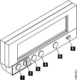
Figure 2. Operator Panel
From left to right in Figure 2, the push buttons and the indicator are as follows:
Reset 1
A push button that allows the service representative to perform a device power-on reset.
Note: It is recommended that all SCSI ports be taken offline before resetting the drive. See “Services Menu” on page 33.
Change Mode 2
A push button that allows the service representative to toggle between service representative mode and Normal mode. Service representative mode can be selected at any time, but the mode will not become active until the device completes all current operations. Normal mode can be selected at any time. Selecting Normal mode returns the operator panel menu to the Operator menu (that indicates status and conditions). Service representative mode enables special menus on the operator panel display not available to the operator in Normal mode.
Up Arrow 3
A push button that allows the operator or the service representative to move the cursor arrow up through the menu options.
Down Arrow 4
A push button that allows the operator or the service representative to move the cursor arrow down through the menu options.
Chapter 3. Drive Operator Panel and Controls 7
Enter 5
A push button that allows the operator or the service representative to select the menu option at the location of the cursor arrow.
Processor Check 6
An indicator LED that switches on for 10 to 20 seconds during a normal power-on or a power-on reset. If no fault is detected, the LED switches off. If the LED remains on, the 3590 requires service.
8 3590 Operator Guide
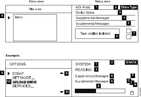
Table 2 identifies the various drive type indicators 2 of Figure 3 and Table 3 describes the panel areas it illustrates.
Figure 3. Options and Status Screen
Table 2. Drive Type Indicator
|
|
|
|
3590E with |
|
Drive Type |
3590 Base |
ULTRA |
3590E |
Fibre |
|
|
|
|
|
Channel |
|
|
|
|
|
|
|
Non-Extended High Performance |
|
ULTRA |
3590E |
N/A |
|
Cartridge / older microcode |
|
||||
|
|
|
|
||
|
|
|
|
|
|
Non-Extended High Performance |
B11 |
B11-U |
E11 |
E11-F |
|
Cartridge / newer microcode ACF |
|||||
|
|
|
|
||
|
|
|
|
|
|
Non-Extended High Performance |
B1A |
B1A-U |
E1A |
E1A-F |
|
Cartridge / newer microcode non-ACF |
|||||
|
|
|
|
||
|
|
|
|
|
|
Extended High Performance Cartridge |
B11-X |
B11UX |
E11-X |
E11FX |
|
ACF |
|||||
|
|
|
|
||
|
|
|
|
|
|
Extended High Performance Cartridge |
B1A-X |
B1AUX |
E1A-X |
E1AFX |
|
non-ACF |
|||||
|
|
|
|
||
|
|
|
|
|
Chapter 3. Drive Operator Panel and Controls 9
Table 3. Options and Status
Area |
Description |
|
|
|
|
|
Displays as manual, automatic, system, accumulate, or random when the |
|
ACF Mode 1 |
ACF is installed. |
|
When the operator changes modes, any current ACF operation (cartridges |
||
|
||
|
in transit) are completed before the request is granted. |
|
|
|
|
Drive Type 2 |
Table 2 provides the history of drive type indicators. |
|
|
|
|
|
v Cleaning: A cleaning cartridge is in the device. |
|
|
v Ready: A ready message is generated by the device when it is ready and |
|
|
other higher-priority messages do not apply. The ready indicator is |
|
|
displayed only when the transport is not moving tape. When ready or not |
|
|
ready, the state of the device is the same to both SCSI busses. |
|
|
v Ready at load point: The media is at the beginning of tape and the device |
|
|
is ready. |
|
|
v Accessing: The empty ACF transport is moving to a magazine position to |
|
|
either check for an unused volume or to get a volume to load. |
|
|
v Transferring: The device is moving a cartridge from the magazine or the |
|
|
priority cell to the drive, or from the drive to the magazine or the |
|
Drive and ACF |
priority cell. |
|
v Loading: The cartridge is being loaded into the drive. |
||
Status 3 |
||
|
v Locating: The device is moving the tape to a specific location. |
|
|
v Reading: The device is reading data from the tape to the device buffer. |
|
|
v Writing: The device is writing data to the tape from the device buffer. |
|
|
v Erasing: The device is logically erasing data from the tape. |
|
|
v Rewinding: The device is rewinding the tape to the beginning of the |
|
|
logical volume. |
|
|
v Unloading: The cartridge is being removed from the drive. |
|
|
v ACF Disabled: The ACF cannot perform an operation; for example, the |
|
|
magazine is not installed or the magazine was filled and the last |
|
|
imported cartridge was returned to the priority cell. |
|
|
v Blank Field: The ACF is inactive and the drive is not loaded. |
|
|
|
10 3590 Operator Guide
Loading...