


GENETX TM
GUITAR
PROCESSOR
USER’S GUIDE

These symbols are internationally accepted symbols that warn of potential hazards with electrical products.The lightning flash means that there are dangerous voltages present within the unit.The exclamation point indicates that it is necessary for the user to refer to the owners manual.
These symbols warn that there are no user serviceable parts inside the unit. Do not open the unit. Do not attempt to service the unit yourself. Refer all servicing to qualified personnel. Opening the chassis for any reason will void the manufacturer’s warranty. Do not get the unit wet. If liquid is spilled on the unit, shut it off immediately and take it to a dealer for service.
Disconnect the unit during storms to prevent damage.
U.K. Mains Plug Warning
A molded mains plug that has been cut off from the cord is unsafe. Discard the mains plug at a suitable facility. Never under any circumstances should you insert a damaged or cut mains plug into a 13 amp power socket. Do not use the mains plug without the fuse cover in place. Replacement fuse covers can be obtained from your local retailer. Replacement fuses are 13 amps and MUST be ASTA approved to BS1362.
Warning
For your protection, please read the following:
Water and Moisture: Appliances should not be used near water (e.g. near a bathtub, washbowl, kitchen sink, laundry tub, in a wet basement, or near a swimming pool, etc.) Care should be taken so that objects do not fall and liquids are not spilled into the enclosure through openings.
Power Sources: The appliance should be connected to a power supply only of the type described in the operating instructions or as marked on the appliance.
Grounding or Polarization: Precautions should be taken so that the grounding or polarization means of an appliance is not defeated.
Power Cord Protection: Power supply cords should be routed so that they are not likely to be walked on or pinched by items placed upon or against them, paying particular attention to cords at plugs, convenience receptacles, and the point where they exit from the appliance.
Servicing: To reduce the risk of fire or electrical shock, the user should not attempt to service the appliance beyond that described in the operating instructions. All other servicing should be referred to qualified service personnel.
For units equipped with externally accessible fuse receptacle: Replace fuse with same type and rating only.
Safety Instructions
Notice for customers if your unit is equipped with a power cord.
Warning:This appliance must be earthed.
The cores in the mains lead are colored in accordance with the following code:
Green and Yellow - Earth Blue - Neutral Brown - Live
As colors of the cores in the mains lead of this appliance may not correspond with the colored markings identifying the terminals in your plug, proceed as follows:
•The core which is colored green and yellow must be connected to the terminal in the plug marked with the letter E, or with the earth symbol, or colored green, or green and yellow.
•The core which is colored blue must be connected to the terminal marked N, or colored black.
•The core which is colored brown must be connected to the terminal marked L, or colored red.
This equipment may require the use of a different line cord, attachment plug, or both, depending on the available power source at installation. If the attachment plug needs to be changed, refer servicing to qualified service personnel who should refer to the table below.The green/yellow wire shall be connected directly to the unit’s chassis.
CONDUCTOR |
WIRE COLOR |
|||
Normal |
Alt |
|||
|
|
|||
L |
LIVE |
BROWN |
BLACK |
|
N |
NEUTRAL |
BLUE |
WHITE |
|
E |
EARTH GND |
GREEN/YEL |
GREEN |
|
Warning: If the ground plug is defeated, certain fault conditions in the unit or in the system to which it is connected can result in full line voltage between chassis and earth ground. Severe injury or death can then result if the chassis and earth ground are touched simultaneously.
Electromagnetic Compatibility
Operation is subject to the following conditions: •This device may not cause harmful interference.
•This device must accept any interference received, including interference that may cause undesired operation.
•Use only shielded interconnecting cables.
•Operation of this unit within significant electromagnetic fields should be avoided.
I
|
|
DECLARATION OF CONFORMITY |
Manufacturer’s Name: |
DigiTech |
|
Manufacturer’s Address: |
8760 S. Sandy Parkway |
|
|
|
Sandy, Utah 84070, USA |
declares that the product: |
|
|
Product name: |
GNX2 |
|
Note: Product name may be suffixed by the letters EX, EU, JA, and UK. |
||
Product option: |
all (requires Class II power adapter that conforms to the requirements of EN60065, EN60742, or equivalent.) |
|
conforms to the following Product Specifications: |
||
|
Safety: |
IEC60065 (1998) |
|
|
EN 60065 (1993) |
|
EMC: |
EN 55013 (1990) |
|
|
EN 55020 (1991) |
Supplementary Information:
The product herewith complies with the requirements of the Low Voltage Directive 72/23/EEC and the EMC Directive 89/336/EEC as amended by Directive 93/68/EEC.
DigiTech / Johnson
8760 S. Sandy Parkway
Sandy, Utah 84070, USA
Date: May 25, 2001
European Contact:Your local DigiTech / Johnson Sales and Service Office or
Harman Music Group
8760 South Sandy Parkway
Sandy, Utah
84070 USA
Ph: (801) 566-8800
Fax: (801) 568-7573
Warranty
We at DigiTech are very proud of our products and back-up each one we sell with the following warranty:
1.The warranty registration card must be mailed within ten days after purchase date to validate this warranty.
2.DigiTech warrants this product, when used solely within the U.S., to be free from defects in materials and workmanship under normal use and service.
3.DigiTech liability under this warranty is limited to repairing or replacing defective materials that show evidence of defect, pro-
vided the product is returned to DigiTech WITH RETURN AUTHORIZATION, where all parts and labor will be covered up to a period of one year. A Return Authorization number may be obtained from DigiTech by telephone.The company shall not be liable for any consequential damage as a result of the product's use in any circuit or assembly.
4.Proof-of-purchase is considered to be the burden of the consumer.
5.DigiTech reserves the right to make changes in design, or make additions to, or improvements upon this product without incurring any obligation to install the same on products previously manufactured.
6.The consumer forfeits the benefits of this warranty if the product's main assembly is opened and tampered with by anyone other than a certified DigiTech technician or, if the product is used with AC voltages outside of the range suggested by the manufacturer.
7.The foregoing is in lieu of all other warranties, expressed or implied, and DigiTech neither assumes nor authorizes any person to assume any obligation or liability in connection with the sale of this product. In no event shall DigiTech or its dealers be liable for special or consequential damages or from any delay in the performance of this warranty due to causes beyond their control.
NOTE:The information contained in this manual is subject to change at any time without notification. Some information contained in this manual may also be inaccurate due to undocumented changes in the product or operating system since this version of the manual was completed.The information contained in this version of the owner's manual supersedes all previous versions.
II
IV
Introduction . . . . . . . . . . . . . . . . . . . . . . . . . . |
.1 |
Quick Start . . . . . . . . . . . . . . . . . . . . . . . . . . . . . . . . |
2 |
Making Connections . . . . . . . . . . . . . . . . . . . . . . |
2 |
Apply Power . . . . . . . . . . . . . . . . . . . . . . . . . . . . |
2 |
Select an Output Mode . . . . . . . . . . . . . . . . . . . |
2 |
Select The Target System Setup . . . . . . . . . . . . . . |
2 |
Select a Preset . . . . . . . . . . . . . . . . . . . . . . . . . . |
2 |
A Guided Tour of the GNX2 . . . . . . . . . . . . . . . . . . |
3 |
The Front Panel . . . . . . . . . . . . . . . . . . . . . . . . . |
3 |
The Rear Panel . . . . . . . . . . . . . . . . . . . . . . . . . . |
6 |
Getting Started . . . . . . . . . . . . . . . . . . . . . . . . . . . . . |
7 |
Making Connections . . . . . . . . . . . . . . . . . . . . . . |
7 |
Mono Operation . . . . . . . . . . . . . . . . . . . . . |
7 |
Stereo Operation . . . . . . . . . . . . . . . . . . . . . |
7 |
Direct to a Mixing Console . . . . . . . . . . . . . |
8 |
S/PDIF Digital Output . . . . . . . . . . . . . . . . . . . . . |
8 |
Applying Power . . . . . . . . . . . . . . . . . . . . . . . . . |
8 |
About the GNX2 . . . . . . . . . . . . . . . . . . . . . . . . . . . |
9 |
The Presets . . . . . . . . . . . . . . . . . . . . . . . . . . . . |
9 |
Performance Mode . . . . . . . . . . . . . . . . . . . . . . . |
9 |
Preset Mode . . . . . . . . . . . . . . . . . . . . . . . . . . . . |
9 |
FX Mode . . . . . . . . . . . . . . . . . . . . . . . . . . . . . . |
9 |
The Footswitches . . . . . . . . . . . . . . . . . . . . . . . . |
10 |
The Expression Pedal . . . . . . . . . . . . . . . . . . . . |
10 |
Bypass Mode . . . . . . . . . . . . . . . . . . . . . . . . . . . |
10 |
Tuner Mode . . . . . . . . . . . . . . . . . . . . . . . . . . . . |
10 |
Jam-A-Long . . . . . . . . . . . . . . . . . . . . . . . . . . . . . |
10 |
Learn-A-Lick Mode . . . . . . . . . . . . . . . . . . . . . . . |
11 |
Rhythm Trainer . . . . . . . . . . . . . . . . . . . . . . . . . . |
11 |
Editing Functions . . . . . . . . . . . . . . . . . . . . . |
13 |
Editing/Creating a Preset . . . . . . . . . . . . . . . . . . . . . . |
13 |
Amp/Cabinet Modeling . . . . . . . . . . . . . . . . . . . . . . . |
13 |
Amp Models . . . . . . . . . . . . . . . . . . . . . . . . . . . . |
13 |
Cabinet Types . . . . . . . . . . . . . . . . . . . . . . . . . . . |
13 |
Editing Amp Models and Cabinet Types . . . . . . . . |
13 |
Selecting Amp/Cabinet Models . . . . . . . . . . . |
14 |
Adjusting Amp Parameters . . . . . . . . . . . . . . |
14 |
Cabinet Tuning . . . . . . . . . . . . . . . . . . . . . . . |
14 |
Creating HyperModels™ . . . . . . . . . . . . . . . . . . |
15 |
Saving HyperModels™ (Amp Save) . . . . . . . . |
15 |
Editing the Effects . . . . . . . . . . . . . . . . . . . . . . . . . . . |
15 |
Storing/Copying a Preset . . . . . . . . . . . . . . . . . . |
16 |
Effects and Parameters . . . . . . . . . . . . . . |
18 |
Effect Definitions . . . . . . . . . . . . . . . . . . . . . . . . . . . . |
18 |
Wah-Pickup . . . . . . . . . . . . . . . . . . . . . . . . . . . . |
18 |
Compressor . . . . . . . . . . . . . . . . . . . . . . . . . . . |
18 |
Whammy/IPS . . . . . . . . . . . . . . . . . . . . . . . . . . . |
19 |
Intelligent Pitch Shifting (IPS) . . . . . . . . . . . . . . . |
19 |
Detuning . . . . . . . . . . . . . . . . . . . . . . . . . . . . . . |
20 |
Pitch Shifter . . . . . . . . . . . . . . . . . . . . . . . . . . . . |
20 |
Stomp Box Modeling . . . . . . . . . . . . . . . . . . . . . |
20 |
EQ . . . . . . . . . . . . . . . . . . . . . . . . . . . . . . . . . . . |
21 |
Noise Gate . . . . . . . . . . . . . . . . . . . . . . . . . . . . . |
21 |
Talker™ . . . . . . . . . . . . . . . . . . . . . . . . . . . . . . . . |
22 |
Chorus/Mod Effects . . . . . . . . . . . . . . . . . . . . . . |
22 |
Chorus . . . . . . . . . . . . . . . . . . . . . . . . . . . . . |
22 |
Flange . . . . . . . . . . . . . . . . . . . . . . . . . . . . . . |
23 |
Phaser . . . . . . . . . . . . . . . . . . . . . . . . . . . . . |
23 |
Triggered Flanger . . . . . . . . . . . . . . . . . . . . . |
24 |
Triggered Phaser . . . . . . . . . . . . . . . . . . . . . . |
24 |
Tremolo . . . . . . . . . . . . . . . . . . . . . . . . . . . . |
24 |
Panner . . . . . . . . . . . . . . . . . . . . . . . . . . . . . |
25 |
Vibrato . . . . . . . . . . . . . . . . . . . . . . . . . . . . . |
25 |
Table of Contents |
|
Rotary Speaker . . . . . . . . . . . . . . . . . . |
. . . . .25 |
AutoYa™ . . . . . . . . . . . . . . . . . . . . . . . |
. . . .25 |
YaYa™ . . . . . . . . . . . . . . . . . . . . . . . . . |
. . . .26 |
SynthTalk™ . . . . . . . . . . . . . . . . . . . . . |
. . . .26 |
Envelope Filter . . . . . . . . . . . . . . . . . . . |
. . . .26 |
Detune . . . . . . . . . . . . . . . . . . . . . . . . . |
. . . .27 |
Pitch Shift . . . . . . . . . . . . . . . . . . . . . . . |
. . . .27 |
Delay . . . . . . . . . . . . . . . . . . . . . . . . . . |
. . . .27 |
Reverb . . . . . . . . . . . . . . . . . . . . . . . . |
. . . .28 |
Tutorial . . . . . . . . . . . . . . . . . . . . . . . . . . . |
. . . .29 |
Select a Preset . . . . . . . . . . . . . . . . . . . . . . . . . |
. . . .29 |
Create a HyperModel™ . . . . . . . . . . . . . . . . . . |
. . . .29 |
Select the Green Channel Amp and Cabinet |
. . . .29 |
Select the Red Channel Amp and Cabinet |
. . . . .29 |
Adjust the Green Channel Parameters . . . . |
. . . .30 |
Adjust the Red Channel Parameters . . . . . . |
. . . .30 |
Tune the Cabinets (optional) . . . . . . . . . . . |
. . . .31 |
Warp the Green and Red Channels Together . . .31 |
|
Save the HyperModel™ . . . . . . . . . . . . . . . |
. . . .31 |
Select Models for the Preset’s Channels . . . |
. . . .32 |
Edit the Preset . . . . . . . . . . . . . . . . . . . |
. . . .32 |
Select the Pickup Type . . . . . . . . . . . . . |
. . . .32 |
Turn the Compressor Off . . . . . . . . . . |
. . . .33 |
Turn the Whammy™/IPS Off . . . . . . . . |
. . . .33 |
Turn the Stompbox Modeling Off . . . . . |
. . . .33 |
Adjust the Noise Gate . . . . . . . . . . . . . |
. . . .34 |
Turn the Talker™ Off . . . . . . . . . . . . . . |
. . . .34 |
Select and Adjust the Chorus . . . . . . . |
. . . .34 |
Turn the Delay Off . . . . . . . . . . . . . . . . |
. . . .35 |
Select and Adjust the Reverb . . . . . . . . |
. . . .35 |
Store the Preset . . . . . . . . . . . . . . . . . . |
. . . .35 |
Other Functions . . . . . . . . . . . . . . . . . . |
. . . .37 |
Expression Pedal . . . . . . . . . . . . . . . . . . . . . . . . |
. . . .37 |
LFOs . . . . . . . . . . . . . . . . . . . . . . . . . . . . . . |
. . . .37 |
Amp Footswitch . . . . . . . . . . . . . . . . . . . . |
. . . .38 |
Expression Parameter Assignment List . . . . |
. . . .38 |
Utilities . . . . . . . . . . . . . . . . . . . . . . . . . . . . . . . |
. . . .39 |
Mono/Stereo Output . . . . . . . . . . . . . . . . . |
. . . .40 |
Target System Setup . . . . . . . . . . . . . . . . . . |
. . . .40 |
Volume Pedal Update . . . . . . . . . . . . . . . . . |
. . . .40 |
V-Switch Threshold . . . . . . . . . . . . . . . . . . . |
. . . .40 |
Expression Pedal Calibration . . . . . . . . . . . |
. . . .41 |
Bank Names . . . . . . . . . . . . . . . . . . . . . . . . |
. . . .41 |
MIDI Channel . . . . . . . . . . . . . . . . . . . . . . . |
. . . .42 |
Bulk Dump . . . . . . . . . . . . . . . . . . . . . . . . . |
. . . .42 |
MIDI Preset Dump . . . . . . . . . . . . . . . . . . . |
. . . .42 |
User Amp Dump . . . . . . . . . . . . . . . . . . . . |
. . . .43 |
MIDI Mapping . . . . . . . . . . . . . . . . . . . . . . . |
. . . .43 |
MIDI Merge . . . . . . . . . . . . . . . . . . . . . . . . |
. . . .43 |
Digital Level . . . . . . . . . . . . . . . . . . . . . . . . |
. . . .44 |
Factory Reset . . . . . . . . . . . . . . . . . . . . . . . |
. . . .44 |
GenEdit™ Editor/Librarian . . . . . . . . . . . . . |
. . . .45 |
PC . . . . . . . . . . . . . . . . . . . . . . . . . . . . |
. . . .45 |
Mac . . . . . . . . . . . . . . . . . . . . . . . . . . . |
. . . .45 |
Appendix . . . . . . . . . . . . . . . . . . . . . . . . . . . . . |
. . . .46 |
Preset List . . . . . . . . . . . . . . . . . . . . . . . . . . . . . |
. . . .46 |
MIDI CC List . . . . . . . . . . . . . . . . . . . . . . . . . . |
. . . .47 |
MIDI Implementation . . . . . . . . . . . . . . . . . . . . |
. . . .48 |
Specifications . . . . . . . . . . . . . . . . . . . . . . . . . . |
. . . .48 |
V

Introduction
Introduction
The DigiTech GNX2, is the most advanced guitar processor of its kind. Thanks to the highly advanced technology provided by GeNetX™, and the extreme horsepower contained in the Audio DNA™ DSP engine, you now have the tools to literally create your own guitar amplifier and speaker cabinet models. All of this power lets you create a sound that is your own. In addition to designing models, the GNX2 has a library full of studio quality effects.
The intuitive user interface makes programming as simple as turning a knob. However, your time would be well spent by reading through this User’s Guide with your GNX2 in front of you.
Included Items
Before you tear open the packaging and toss the manual over your shoulder, please check to make sure the following items have been included:
•GNX2
•PSS3 Power Supply
•Warranty Card
•User’s Guide
•GenEdit™ Editor/Librarian CD
The utmost care was taken in the manufacturing and packaging your GNX2. Everything should be included and in perfect working condition. However, if you find anything missing, please contact the factory at once. Please take a moment to fill out the warranty card. It is your safeguard in the unlikely event that the GNX2 develops a problem.
 1
1

Introduction
Quick Start
The Quick Start section is included for those of you who would rather play now and read later.
Making Connections
Connect your instrument to the INPUT jack on the rear panel. Connect the LEFT/RIGHT OUTPUTS to the input(s) of your amplifier(s), power amp, or mixer.
Apply Power
Turn the OUTPUT knob on the rear panel of the GNX2 all the way down (fully counter clockwise). Connect the plug of the PSS3 power supply to the POWER jack on the GNX2. Connect the other end of the PSS3 power supply to an AC outlet and turn the GNX2 POWER switch on. Turn your amplifier(s) on, and adjust the volume(s) to a normal playing level. Gradually increase the GNX2’s OUTPUT volume.
Select an Output Mode
Press the UTILITY button and use the DATA WHEEL to select either the Stereo or Mono output mode.
Select The Target System Setup
The GNX2 needs to know the type of amplification system it will be used with. After selecting an Output, press the RHYTHM button. The Target System Setup menu is displayed. Use the DATA WHEEL to select an amplification system, and press EXIT to return to Performance mode.
Select a Preset
The GNX2 comes with 64 pre-programmed Factory Presets, and 64 User Presets. From the factory, the User Presets are exact duplicates of the Factory Presets.This lets you experiment without losing any of the original presets.
Use the BANK footswitches to select a Bank, and Footswitches 1-4 to select a preset. The DATA WHEEL can also be used to select a preset. After you find a preset you like, you can edit it. See Editing and Creating a Preset page 13.
2

Introduction
A Guided Tour of the GNX2
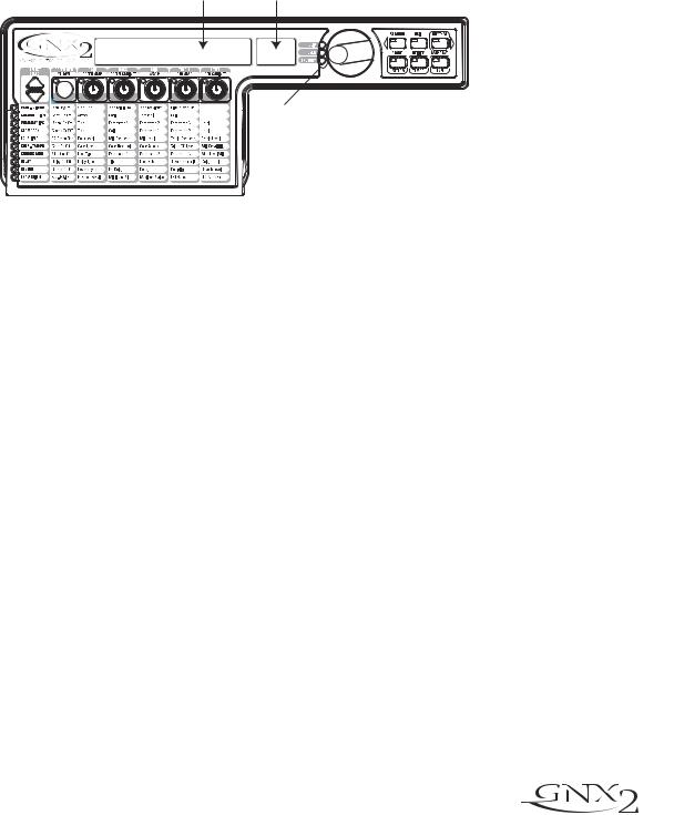
The Front Panel
1. Footswitches 1- 4
Depending on the selected mode, these 4 footswitches select presets, change amp channels, and turn individual effects on and off. Bypass, accesses the Tuner, or controls Learn-A-Lick functions.
2. Matrix
The Matrix LEDs light identifying the active effects for the selected preset in performance mode, or the selected row of effects in edit mode.
3. Effect Select Buttons
The Effect Select buttons are used together with the Matrix LEDs to choose the effects you want to edit.
4. Status Button
In performance mode, the Status button selects the Green or Red Amp Channel. It also activates the amp and cabinet Warping feature (indicated by a yellow LED next to the Status button). In Edit mode it turns the selected effect on and off, or selects a controller type for the expression assignment.
5. Parameter Knobs
In performance mode, these 5 knobs select Amp Models, Speaker Cabinets, and Warp Models. In Green or Red mode, they adjust the Amp Gain, EQ and Level of the selected amp channel. In Edit mode, they adjust the parameters listed in the column directly below each knob for the selected group of effects.
 3
3

Introduction
6. Display
The display consists of eight green alpha-numeric characters, and two red numeric digits. The display provides information for several different functions depending on the selected mode. In Performance mode, the display shows the selected preset name and number. The display also shows bank names when changing banks, and momentarily flashes the active amp channel when the amp channel is changed. In Edit mode, the alpha-numeric display shows the selected effect’s parameter and value or status. In Tuner mode, the numeric display shows the note played and the alpha-numeric display indicates whether the note was sharp or flat. In Learn-A-Lick mode, the alpha-numeric display shows the selected function and the numeric display provides an elapsed time for record and playback.
7. Data Wheel
The Data Wheel increases and decreases the selected preset in performance mode. It increases and decreases the value or status of the selected Utility or Rhythm function, and scrolls characters in the naming procedure.
8. Mode Buttons
These 6 buttons select GNX2 modes of operation. The Exit button is only used to exit a function, while the other 5 buttons perform dual functions dependent on the selected mode of operation. The buttons are labeled as follows:
FX MODE - The FX Mode button assigns footswitches 1-4 to presets within a selected Bank, or toggles individual effects in a selected preset on and off. The FX Mode button is lit when footswitches 1-4 toggle effects on and off. This button also selects the previous character when naming a preset, and the previous menu in Utility mode. The Mode Down/Up footswitches functionality changes depending on the status of the FX Mode button. (see Mode Footswitches section below).
EXIT - Exits all functions and returns to Performance mode.
RHYTHM - The Rhythm button accesses the Rhythm Trainer feature in the GNX2. When the Rhythm Trainer is selected, the LED lights and the drum loop begins playing. The bottom row of Mode buttons can also be used in conjunction with the Data Wheel to select and edit the Pattern,Tempo, and Level. This button also selects the next character when naming a preset, and the next menu in Utility mode.
STORE - The Store button is used to save your custom edits to the User presets.The function of this button changes to select Pattern in Rhythm mode.
UTILITY - The Utility button accesses global functions including Output Mode,Target System Setup, and MIDI setup.
AMP SAVE - This button stores Amp and Cabinet changes (tone, gain, level, amp type, cabinet type, warp, or cabinet tuning) as HyperModels™. This button also selects the level in Rhythm mode.
9. Mode Footswitches
These footswitches select User Preset Banks, presets, and playback speed (Learn-A-Lick), depending on the current mode. Press the Up and Down footswitches at the same time to toggle in and out of FX Mode. In FX Mode, these footswitches scroll through the presets. When FX Mode is disabled,
4
Introduction
these footswitches move through the User Preset Banks. In Learn-A-Lick™ Mode, these footswitches select the playback speed of the sampled phrase.
10. Expression Pedal
The Expression Pedal controls effect parameters in real time. Most GNX2 parameters can be assigned to the Expression Pedal. Applying extra pressure to the toe of the Expression Pedal switches between controlling the assigned parameter(s) and controlling the Wah.
 5
5
Introduction
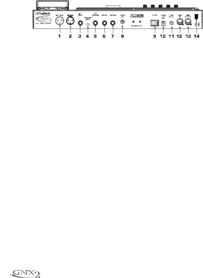
The Rear Panel
1. Mic Output
This XLR jack passes your mic signal to the house mixing console.
2. Mic Input
This XLR jack connects a low impedance mic to the GNX2 that can be used with the Talker and Vocoder effects. A mic with a cardioid pattern is recommended.
3. Input Jack
Connect your instrument to this jack.
4. Jam-A-Long Jack
Use a 1/8” stereo plug to connect this jack to the output of a tape or CD player. This lets you play along with the music, or record a musical passage.
5. Headphone Output
Connect stereo headphones to this jack. Be sure to set the Target System Setup mode to Direct when listening through Headphones (see page 40 for more information on selecting the Target System Setup). Do not connect a mono plug to this jack, because you may damage the output driver.
6. Left Output
Connect to the input of an amplifier, input of a power amp, or line input of a mixing console.
7. Right Output
Use this jack in conjunction with the Left Output for stereo applications. Connect to the input of a second amplifier, or the right input of a stereo power amp.
8. Output Level
Controls the overall volume level of the GNX2.
9. Power Switch
Turns the power on and off.
10. Power Input
Connect only the provided DigiTech PSS3 power supply to this jack.
11. S/PDIF Output
This is the GNX2’s digital output . The signal at this output is in a stereo digital format, and is to be connected to a digital S/PDIF input such as those found on digital recording devices.
NOTE: Do not connect the S/PDIF output to analog auxiliary, CD, phono, or tape inputs on consumer electronic devices. It is not compatible with these inputs.
6
Introduction
12. MIDI In
This jack receives all incoming MIDI data. Connect this jack to the MIDI out of a computer, sequencer, MIDI controller, or MIDI storage device.
13. MIDI Out/Thru
This jack sends MIDI data from the GNX2. Connect this jack to the MIDI in of a computer, or external MIDI recording device. When enabled, MIDI Thru sends the same information the GNX2 received at the MIDI In.
14. Strain Relief
This secures the power cord and to help prevent it from disconnecting during a performance.
Getting Started
Making Connections
The GNX2 has several different connection options. You can run mono into an amp or power amp, stereo into two amps or a stereo power amp, direct into a mixing console, or any combination of these. Before connecting the GNX2, make sure both the GNX2 and the amplifier are OFF. The following diagrams show some examples.
NOTE:The type of amplification system the GNX2 will be used with should be selected at the Target System Setup of the Utility menu. See page 40 for more information about selecting the Target System Setup.
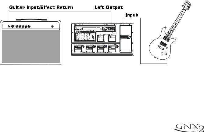
Mono Operation
1.Connect your guitar to the input of the GNX2.
2.Connect the GNX2’s left output to the instrument input on your amplifier, or to the line input of a power amp.
3.Select Mono as the Output mode from the Utility menu. See page 40 for more on selecting the Output mode.
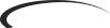
Stereo Operation
1.Connect the guitar to the input of the GNX2.
2.Connect the GNX2’s Left output to the input of one amplifier or channel of a power amp.
3.Connect the GNX2’s right output to a second amplifier, or to a second channel of a power amp.
4.Select Stereo as the Output mode from the Utility menu. See page 40 for more on selecting the Output mode.
 7
7
Introduction
Direct to a Mixing Console
The GNX2 can be connected directly to the inputs of a house PA system, or a recording console.
1.Connect the guitar to the GNX2’s input.
2.Connect the GNX2’s outputs to the channel inputs of the mixing console.
3.If the GNX2 is to be used in Stereo mode, set the pan controls of the mixer hard left and right, and select Stereo as the output mode from the Utility menu. See page 40 for more information on the Output mode.
S/PDIF Digital Output
The GNX2 includes a digital S/PDIF output that connects directly to the latest digital recording devices and sound cards. Connect the GNX2’s S/PDIF output to the S/PDIF input on your digital mixer or recorder. You must have S/PDIF inputs on the receiving device in order to use this output. Be sure to use a 75 ohm or RCA video cable to connect from the Digital Output to a recording device. You can use the analog and digital outputs of the GNX2 simultaneously.
NOTE: Do not connect the S/PDIF output to analog auxiliary, CD, phono, or tape inputs on consumer electronic devices. It is not compatible with these inputs.
Applying Power
Once the audio connections are made, turn the GNX2’s Output Level on the rear panel all the way down (counterclockwise). Connect the PSS3 to the power jack on the back of the GNX2 and the other end to an AC outlet. Turn the power switch On. Turn the power to your amplifier(s) on. Set the amp(s) to a clean tone and set the tone controls to a flat EQ response (on most amps, this would be 0 or 5 on the tone controls). Turn the Output Level of the GNX2 up to increase the volume.
8
Introduction
About the GNX2
The Presets
A preset is a named and numbered location of a programmed sound that resides in the GNX2. Presets can be recalled with the FOOTSWITCHES or the DATA WHEEL. The GNX2 comes with 64 Factory and 64 User presets. The Factory Presets do not let you store changes to them. The User presets let you store changes. From the factory, the 64 User presets are exact duplicates of the 64 Factory presets. This lets you make your own presets without worrying about losing any of the original presets. When you select a preset, the name of the preset appears in the green alpha-numeric display and the number of the preset appears in the red numeric display. The User LED to the right of the numeric display lights indicating the User preset is active. The Factory LED lights indicating a Factory preset is active.
Preset Name |
Preset Number |
NAMES |
64 |
LEDs Indicate Whether a User
or Factory Preset is Active
Performance Mode
When you first apply power to the GNX2, it powers up in Performance mode. This is the mode used while you are performing. While in Performance mode, the display shows the selected preset’s name and number. The vertical LEDs on the Matrix indicate which effects are active for the selected preset. From Performance mode, you have access to all of the GNX2’s presets.
Preset Mode
Preset Mode is the factory default operation mode when the GNX2 is first powered up. In Preset mode, Footswitches 1-4 select presets in the current bank. The Mode footswitches are used to select the 16 User Banks. Successive presses of the MODE footswitches advances through all User/Factory Banks. Pressing and holding a MODE footwitches scrolls through the User Banks. Once a Bank has been selected, a preset within that bank needs to be selected. If a preset is not selected within 5 seconds, the GNX2 returns to the previous bank and preset.
FX Mode
FX Mode is another mode of operation that can be used during a performance. The FX MODE button (located to the right of the Data Wheel) is used to switch between Preset and FX Modes. When FX Mode is active, the FX MODE button lights. In FX MODE, the 1-4 Footswitches turn on and off the effects. Footswitch 1 switches between the Green, Red, and Yellow amp channels. Footswitch 2 turns the Chorus/Mod Effects module on and off. Footswitch 3 turns the Delay on and off. Footswitch 4 turns the Reverb on and off. The Mode footswitches are used to navigate through all of the GNX2’s presets.
As an added feature, the Delay footswitch can be used as a tap-tempo switch for setting the delay time during live performance. While the delay is on, press and hold the Delay footswitch while in FX Mode to turn it into a tap-tempo delay switch. Press and hold it again to change it back to a Delay on and off
 9
9

Introduction
The Footswitches
The GNX2 1-4 footswitches are primarily used to select presets or turn on and off effects, depending on which mode is selected. However, these footswitches are also used to access other GNX2 functions. For example, pressing Footswitches 1 and 2 simultaneously, or pressing the lit Footswitch (in Preset mode) bypasses the the current preset. Pressing Footswitches 2 and 3 simultaneously accesses the Tuner mode. Pressing Footswitches 3 and 4 simultaneously activates the Learn-A-Lick mode. In Learn-A-Lick mode, Footswitches 1-4 control various Learn-A-Lick functions.
The Expression Pedal
As you go through the different presets in the GNX2, you will find that the expression pedal has different functions.The Expression Pedal can control three different parameters in each Preset. Rock the Expression Pedal back and forth to change the values of the assigned parameters. The pedal can control assigned minimum and maximum values (stop points) for each parameter. The Expression Pedal also includes a feature called V-Switch that allows you to override the Parameters assigned to the Expression Pedal and replace them with the Wah effect. See page 37 for more information on assigning the Expression Pedal.
Bypass Mode
The GNX2 presets can be bypassed for a clean, unprocessed guitar tone. Bypass mode turns off all effects and modeling. To bypass the GNX2 in Preset mode, press the active preset’s Footswitch (the 1-4 footswitch that is lit), or press Footswitches 1 and 2 simultaneously. To bypass the GNX2 while in FX Mode, press Footswitches 1 and 2 simultaneously. When the GNX2 is bypassed, the display reads BYPASS and all LEDs in the matrix are off. Press any Footswitch to exit Bypass and return to the last preset. The Matrix and Programming buttons are not available in Bypass mode.
Tuner Mode
The Tuner in the GNX2 lets you quickly tune or check the tuning on your guitar. Press Footswitches 2 and 3 simultaneously to enter Tuner mode. The display briefly flashes TUNER. To begin tuning, play a note on your guitar (a harmonic at the 12th fret usually works best).The red numeric display shows the note being played, and the green alpha-numeric display indicates whether the note is sharp or flat. Arrows to the left (<<<) indicate the note is sharp and should be tuned down. Arrows to the right (>>>) indicate the note is flat and should be tuned up. When your note is in tune, -><- is displayed.
In Tuner mode, you can set your tuning reference with the Data Wheel. The default factory setting is A=440 Hz. The tuning references range from 427 Hz to 453 Hz (± 50 cents (1/2 semitone) from either direction of 440 Hz). Below 427 Hz, are alternate dropped tunings. The alternate tunings are REF Ab (A=Ab), REF G (A=G), and REF Gb (A=Gb). The display window briefly flashes the selected tuning preference.
Exit tuner mode by pressing any of the Footswitches.
Jam-A-Long
The Jam-A-Long feature lets you connect a Tape, CD, or MP3 player to the GNX2. The tape, CD, or MP3 player’s signal is output through the GNX2’s left, right, and headphone outputs. To use the Jam-A-Long feature, connect the headphone output of your player to the JAM-A-LONG INPUT on the rear panel of the GNX2. Use a 1/8” stereo cable, and press play on your Tape, CD, or MP3 player.
10

Introduction
Learn-A-Lick Mode
The Learn-A-Lick function allows you to record a 9 second passage of music and play it back as slowly as 1/4 the original speed with no change in pitch. This is very useful for picking out the notes of a fast guitar solo.
There are 6 Learn-A-Lick functions.They are:
•Stop (Controlled by Footswitch 1)
•Play (Controlled by Footswitch 2)
•Rewind (Controlled by Footswitch 3)
•Record (Controlled by Footswitch 4)
• Tempo Down (Controlled by rotating the Data Wheel counter-clockwise)
• Tempo Up (Controlled by rotating the Data Wheel clockwise)
Using Learn-A-Lick
1.Connect the player’s headphone output to the Jam-A-Long input jack on the rear panel using a 1/8” stereo plug. Set the volume level of the player.
2.Find the passage you want to record and pause the Tape, CD, or MP3 player.
3.Press and hold the number 2 and 3 Footswitches to enter Learn-A-Lick mode.The display reads:
Lrn LICK
4.Release the pause button on your playback device and press the number 4 Footswitch. The display reads: RECORD. The red numeric display provides a time elapsed reference while recording is in process. When recording is complete, the recorded passage is set in an auto-loop playback mode indicated by play appearing in the display.
5.Press Stop or Pause on the playback device.
6.Rotate the DATA WHEEL counterclockwise to slow the playback down, or clockwise to increase the playback speed at 1/8 speed intervals.Your interval choices include: FULL, 7/8, 3/4, 5/8,
1/2, 3/8, and 1/4 speeds.
7.Press Footswitch 3 to step back through the loop at 1 second intervals.
8.The EXPRESSION PEDAL controls the output level of the recorded phrase.
9.To stop the playback, press Footswitch 1.
10.To resume playback, press Footswitch 2.
11.To record a new passage, press Footswitch 4.
12.To exit the Learn-A-Lick mode, press and hold Footswitches 3 and 4, or press EXIT.
Rhythm Trainer
The Rhythm Trainer in the GNX2 is a tool that can be used to develop a great sense of timing, rehearse different musical styles, or just to jam with. The Rhythm Trainer plays sampled drum patterns in an infinite loop. You can select from a variety of patterns, change the tempo, and adjust the playback level while using the Rhythm Trainer. When the Rhythm Trainer is enabled, the drum patterns are mixed with your guitar signal at the GNX2’s left, right, and headphone outputs.
To activate the Rhythm Trainer, follow these steps:
1.Press the RHYTHM button.The Rhythm button’s LED lights and the current drum pattern will begin playing. If Rhythm mode is enabled from Performance mode, the Store, Utility, and Amp Save LEDs light.
2.Press the Store, Utility, or Amp Save buttons to adjust the Pattern,Tempo, or Level using the DATA WHEEL.
 11
11
 Loading...