


50QQ
Table of contents
 Loading...
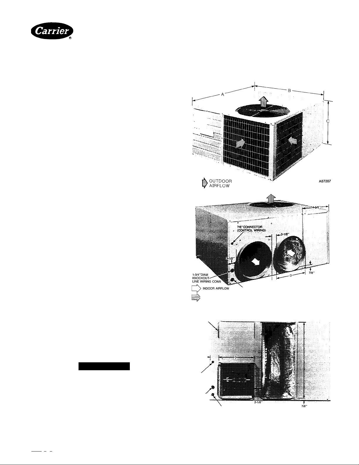
50QQ
#
HEATING A COOLING
Single-Package Heat Pumps
Installation, Start-Up and Service Instructions
CONTENTS
Page
SAFETY CONSIDERATION
INSTALLATION..................................................................1-7
Step 1—Check Equipment and Jobsite............................. 1
• UNPACK UNIT
• INSPECT EQUIPMENT
• COMPLETE SYSTEM REQUIREMENTS
Step 2—Mount Unit.............................................................. 2
• ON THE GROUND
• ON THE ROOF
Step 3—Make Ductwork Connections
• CONNECT RETURN AND SUPPLY AIR
DUCTWORK
Step 4—Provide for Cooling Cycle
Condensate Disposal
• CONNECT DRAIN LINE
Step 5—Make Electrical Connections
• INSTALL A BRANCH CIRCUIT DISCONNECT PER
NEC
• ROUTE LINE POWER LEADS INTO UNIT
• CONNECT GROUND LEAD TO GROUND LUG
• SET INDOOR FAN MOTOR SPEED
• ROUTE CONTROL POWER WIRES
• ACCESSORY DUCT FLANGE KIT INSTALLATION
• ELECTRIC HEATER INSTALLATION
START-UP
SERVICE...........................................................................8-15
............................................................................
SAFETY CONSIDERATIONS
Installing and servicing air conditioning equipment can be
hazardous due to system pressure and electrical compo
nents. Only treuned and qualified service personnel should
install or service air conditioning equipment.
Untrained personnel can perform basic maintenance func
tions such as cleaning coils and filters and replacing filters.
All other operations should be performed by trained service
personnel. When working on air conditioning equipment,
observe precautions in the literature and on tags and labels
attached to unit.
Follow all safety codes. Wear safety glasses and work
gloves. Use quenching cloth for brazing operations. Have
fire extinguisher available.
.................................................
...............................
......................................................
...............................
1
2
4
5
8
1-5/8” DIAM KNOCKOUT ELECTRIC HEAT
> OUTDOOR AIRFLOW
RIGHT-SIDE VIEW - MODEL 018 048(TYPICAL)
DUCT FLANGE
FOR 14”X28”
CONNECTION
A88061
A WARNING
Before performing service or maintenance operations on
7/8”
CONNECTOR^
system, turn off main power switches to unit. Turn off
accessory heater power switch if applicable. Electric
shock can cause personal injury.
INSTALLATION
Step 1—Check Equipment and Jobsite
1-3/8”DIAM
KNOCKOUT
LINE WIRING
CONN
RIGHT - SIDE VIEW • MODEL 060
1-5/8”DIAM KNOCKOUT
ELECTRIC HEAT
UNPACK UNIT—Move unit to final location. Lift off car
ton tEiking special care not to damage unit.
Manufacturer reserves the right to discontinue, or change at any time, specifications or designs without notice and without incurring obiigations.
Bookl 1 I 4 PC 101 Catalog No 565-097 Printed in USA Form 50QQ-8Si 11/87 Pg 1 Replaces: 50QQ-7Si
Tab i5a 15a
Fig. 1 —Dimensions and Connections
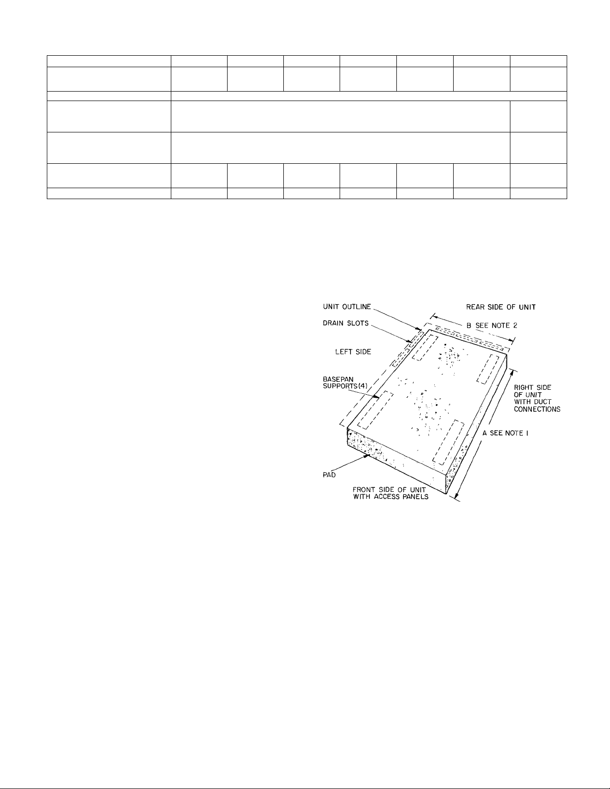
Table 1—Physical Data and bimensions
MODEL 50QQ
REFRIGERANT (R-22)
Operating Charge (lb)
Refrigerant Control
SHIPPING WEIGHT (lb) 323 1 329 1 346 1 357 | 402 | 445 | 484
DIMENSIONS (in.)
DUCT CONNECTIONS (in.)
FILTER SIZE (in.)t
Disposable
Permanent
*Dimension C includes %-in built-in base support channels
tOptional square duct flanges are available as an accessory for 14-in x 14-in duct.
ijiRecommended field-supplied filters are one-in. thick.
A
B
C*
D
E
018 024
7 lbs 4 oz
20x25 20x25 (2)15x20
15x20 15x20 20x20
6 lbs 8 oz 8 lbs 0 oz
22'k 1 2472 1 29% 32%
030
Side-By-Side
Round!
036
7 lbs 4 oz
Piston
48
14
15x20
20x20 (2) 20 X 20
20x25
8 lbs 2 oz
INSPECT EQUIPMENT—File claim with shipping com
pany if shipment is damaged or incomplete.
COMPLETE SYSTEM REQUIREMENTS before
installing.
Consult local building codes and National Electrical Code
(NEC) ANSI/NFPA 70-1987 for special installation
requirements.
Provide sufficient space for coil airflow clearance, wiring,
and servicing unit. See Fig. 1 and 2. Locate unit where sup
ply and return air ducts can be conveniently brought out to
unit duct connections.
Unit may be placed with duct side as close to building as
top removal, duct connections and power connections per
mit. Position unit so water or ice from roof does not drop
directly on top of unit or in front of coil. Make provisions for
condensate drainage and defrost water disposal. Maintain a
4-ft clearance above unit for vertical air discharge.
Roof installation method for 50QQ depends on building con
struction and special requirements of local building codes.
Ensure that roof can support unit weight. Protect unit from
prevailing winds to ensure adequate defrost.
Step 2—Mount Unit
NOTES:
1
In areas of snowfall or subfreezing temperatures when elevated
frame Is used Dimension A is 48-in., Dimension B is 42-in. In areas
where elevated frame is not used Dimension A is 45-in , Dimension
B is 39-in
Allow a 3-ft service clearance at front and rear sides of unit
ON THE GROUND—Mount heat pump on an elevated
frame positioned on a level pad. See Fig. 2 for pad dimen
Fig. 2—Pad Dimensions
sions. Ensure pad does not obstruct coil slots in unit basepan. (Slots drain water during heating and defrost cycles.
See Fig. 2 for drain slot locations.) Construct pad to provide
clearance under basepan coil slots for drainage and ice
buildup. In areas where prolonged subfreezing temperatures
or snowfall occur, increase clearance to 12 to 18-in. by con
structing an angle-iron frame to support unit 12 to 18-in. off
base. Design cross angle of frame so as not to obstruct basepan coil slots. See Fig. 3 for recommended frame construc
tion. Alternate construction should follow dimensions.
Extend a 24-in. gravel apron around pad for condensate and
defrost water drainage field.
ON THE ROOF—Mount unit on a level platform or frame.
Elevate unit for proper clearance as described under ground
insteJlation above. Design roof and plan water runoff so as
to prevent unit and its duct flashing from sitting in water,
in accordance with eJl applicable codes.
Step 3—Make Ductwork Connections
CONNECT RETURN AND SUPPLY AIR DUCT
WORK—Connect ductwork to unit supply and return air
duct connections. Refer to Fig. 1 and Table 1 for unit supply
and return air connection sizes and locations.
Flanges are provided on Models 018-048 for round duct con
nections, on Model 060 for rectanguleu- duct connections.
Accessory duct flange kit is available for squeire or rectan
gular connections on 018-048 units. Refer to accessory
Installation Instructions on page 5 for connections to
ductwork.
Fig. 4 shows a typical duct system with 50QQ installed. Do
not operate unit longer than 5 minutes without ductwork or
damage to blower motor may result.
042
20x25
048
9 lbs 0 oz
20x25
20x20
(2) 15x 20 (2) 20 X 20
060
9 lbs 0 oz
Side-By-Side
Rectangular
13"/,eXl3’7,e
13"Ae X 277a
25x25
20x25
A88063
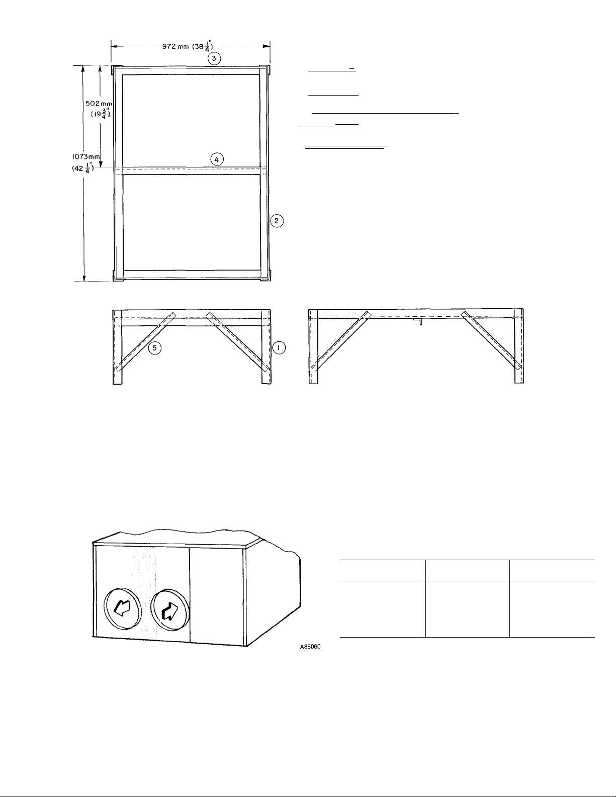
I =\ = = = ^ 305 mm (12") TO 610 mm (24") (4) REQ
I
^ ----- —---------------------------------------------------------------------'(411") (2) REQ
' I ---------------1 I 959mm (37|")(2)REQ
^ I
----------------------
gj I I - |-^ 406 mm (16") (8) REQ
material:
ANGLE IR0N-3L8mm(l^) TO 38mm (1^) COMM'L STD
WELD FRAME TOGETHER
PAINT WITH ZINC-RICH PAINT (RUSTPROOF)
-| 959mm(375 )(l) REQ.
r 38 mm (1-5) 3"
#
Fig. 3—Heat Pump Mounting Frame
When designing and installing ductwork, consider the
following:
1. When connecting ductwork to 042, 048 and 060 units,
do not drill deeper than one inch in shaded area shown
below. Coil may be damaged.
2.
Install field-supplied filters in return air ductwork. Rec
ommended sizes for filters are shown in Table 1.
3.
Avoid abrupt duct size increases and reductions.
Abrupt change in duct size adversely affects air
performance.
4.
Use flexible connectors between ductwork and unit to
prevent transmission of vibration. When electric heater
is installed, use fireproof canvas (or similar heat resis
tant material) connector between ductwork and unit
discharge connection. If flexible duct is used, insert a
sheet metal sleeve inside duct. Heat resistant duct con
nector (or sheet meted sleeve) must extend 24-in. from
electric heat element.
5. Size ductwork for cooling air quantity (cfm). The mini
mum air quantity for proper electric heater operation is
listed below. Heater limit switches may trip at air
quantities below those recommended.
MODEL
50QQ
018
024
030
036
042
048
060
INDOOR FAN
SPEED SETTING
Low 1400
MIN CFM
675
875
875
1400
1700
1800
6. Insulate and weatherproof all external ductwork. Insu
late and cover with a vapor barrier all ductwork pass
ing through unconditioned spaces. Follow latest
SMACNA (Sheet Metal and Air Conditioning Contrac
tors National Association) minimum installation stand
ards for residential heating and air conditioning
systems.
7. Secure all ducts to building structure. Weatherproof
duct openings in wall or roof according to good con
struction practices.
PARAT NO.
99TZ900521
99T2900571
50LQ90002106
50LQ90001106
38RQ900012
50LQ90000106 Outdoor Thermostat (Six 50LQ900001)
50LQ900031
32LT900301
32LT900611
50YM900051
88EM0050MA01
88EM0075MA01
88EM0100MA01
88EM0150MA01
88EM0200MA01
88EM0250MA01
88EM0100EA01
88EM0150EA01
88EM0200EA01
88EM0250EA01
88EM0100FA01
88EM0150FA01
88EM0200FA01
88EM0250FA01
HC95DE023
HC95DD058
HC95DE088
HC95DE208
HN61HB510
HN61KB021
HN61KB075
♦Available through Service Parts
NOTE: Electric heaters are rated at 240 and 480 volts
Thermostat 1 -stage cooling, automatic changeover
Subbase 2-stage heating, Carrier, Honeywell
Thermostat 2-stage cooling, manual changeover
Subbase 2-stage heating, Carrier, Honeywell
Solid-State Time Guard® Control (Six 50LQ900021)
Service Sentry (Six 50LQ900011)
Supplemental Heat Relay—Used with 25 kW heater and 2 outdoor thermostats
Reversible Filter Drier and AccuRater Assembly
Motormaster® Head Pressure Control
Motormaster Head Pressure Control
Duct Flange Kit
Electric Heater—5 kW, 240-1
Electric Heater—7.5 kW, 240-1
Electric Heater—10 kW, 240-1
Electric Heater—15 kW, 240-1
Electric Heater—20 kW, 240-1
Electric Heater—25 kW, 240-1
Electric Heater—10 kW, 240-3
Electric Heater—15 kW, 240-3
Electric Heater—20 kW, 240-3
Electric Heater—25 kW, 240-3
Electric Heater—10 kW, 480-3
Electric Heater—15 kW, 480-3
Electric Heater—20 kW, 480-3
Electric Heater—25 kW, 480-3
Start Capacitor^
Start Capacitor^
Start Capacitor^
Start Capacitor^
Start Relays
Start Relays
Start Relays
Table 2—Accessories
DESCRIPTION
MODEL
50QQ
All
All
All
All
060
All
All
All 208/230-v
All 460-v
018-048
All
All
All
030-060
036-060
060
030-060
030-060
042-060
060
036-060
036-060
036-060
060
018
024, 030
036-048
060
018
024-048
060
Step 4—Provide for Cooling Cycle condensate Disposal-
Condensate may be drained directly onto gravel apron or
connected by drain line(s) to a dry well. Follow local codes.
CONNECT DRAIN LINE to rubber condensate drain fit
ting on side of unit (see Fig. 5). Use clamp provided. Install
factory-supplied condensate trap (taped to indoor fan com
partment for shipment) at end of dredn line. If a drain line is
not used, connect condensate trap to unit drain fitting as
shown in Fig. 4.
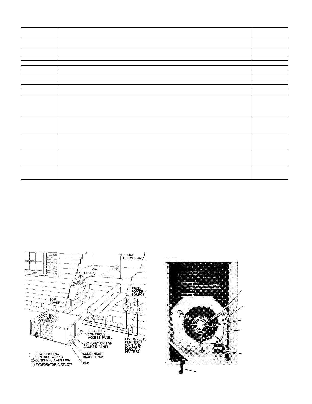
FAN MOTOR
MOUNTING BOLTS
ORIFICE RING
FAN MOTOR
BLOWER
HOUSING
CAPACITOR
♦Separate disconnect per NEC required for electric heater
Fig. 4—Typical Installation
CONDENSATE TRAP
Fig. 5—Condensate Drain and Trap Details
m
step 5—Make Electrical Connections—Install field wiring
in compliance with loced and national fire, safety and electri
cal codes. Be sure voltage to unit is within ± 10% of volt
age indicated on nameplate. Contact local power company
for correction of improper line voltage.
Operation of unit on improper line voltage constitutes
abuse and may cause unit damage that could affect war
ranty.
See Table 3 for recommended fuse sizes.
INSTALL A BRANCH CIRCUIT DISCONNECT PER
NEC of adequate size to handle unit starting current. Pro
vide a separate disconnect for unit and for each accessory
electric heater circuit as required. (See electric heater Instal
lation, Start-Up and Service Instructions.) Locate disconnect(s) within sight from and readily accessible from the
unit, per Section 440-14 of National Electriced Code (NEC).
ROUTE LINE POWER LEADS INTO UNIT-Extend
leads from disconnect per NEC through hole provided
(Fig. 1) into line wiring splice box. Use copper wire only.
CONNECT GROUND LEAD TO GROUND LUG in splice
box for safety. Connect power wiring. See Fig. 7. Connect
line power leads to yellow and black pigtails on single-phase
units.
SET INDOOR FAN MOTOR SPEED-Refer to page 3 for
minimum edlowable eiir quantity for safe electric heater
operation. Indoor fan motor is factory wired for low-speed
operation on all models. Fan motor is equipped with spadetype speed selector terminals marked 1, 2 and 3 on 3-speed
motors (042 and 048), and 1 and 2 on 2-speed motors (018,
024, 030, 036 and 060).
For electric heater operation, set motor at: LOW—sizes 018
through 042, and 060; MED—size 048.
MOTOR TERMINAL
FAN SPEED
(3-speed, 042, 048)
FAN SPEED
(2-Speed, 018-036, 060)
1
High
High
2
Medium
Low
3
Low
—
For air delivery performeuice, refer to Table 4.
ROUTE CONTROL POWER WIRES (24v) through 78-in.
connector provided in unit. Fig. 1. Extend leads to unit con
trol wiring terminal boeu-d in unit control box. Fig. 6. Con
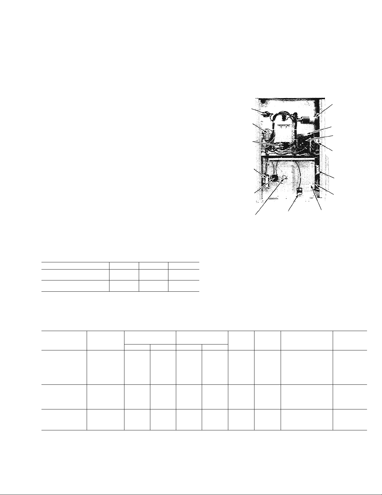
nect leads to terminal board as shown in Fig. 8.
The unit transformer supplies 24-v power for complete sys
tem including accessory electric heater. A resettable circuit
breaker is provided in the 24-v circuit.
RUN
HEATER
CAPACITOR
CONTROL
VOLTAGE
CIRCUIT
BREAKER
CONTROL
BOARD
SUPPLE
MENTAL
HEAT
RELAY
SERVICE
SENTRY
UNIT
GROUNDING
LUG
START
THERMISTOR
TRANSFORMER
CONTACTOR
HEATER
CONTROL RELAY
TIME GUARD
LIM^i7cONTROL S^PLT^AGE GROUNDING
HEATER
connection
Fig. 6—Control Section
ACCESSORY DUCT FLANGE KIT INSTALLATION018-048
1. Refer to Fig. 8 for duct adapter dimensions and hole
locations.
2. Mark hole locations.
MODEL
5000
018
024
030
036
042
048
060
030
036
042
048
060
036
042
048
060
FLA —Full Load Amps
HACR—Heating, Air Conditioning, Refrigeration
IFM —indoor Fan Motor
LRA —Locked Rotor Amps
MCA —Minimum Circuit Amps
OFM —Outdoor Fan Motor
RLA —Rated Load Amps
V-PH
208/230-1 253 187 82 0
208/230-3 253 187 79 5
460-3
Max Min LRA
506 414 398
Table 3—Unit Electrical Data (60 Hz)
OPER
VOLTAGE*
COMPRESSOR
r RLA
50 0
53.0
65.0
106.0
1100
178.0
53 0
67 5
90.0
124.0
33.8
45 0
62.0
9.3 3.5 1 4
11 6 35
13.9
17.2
20 7 35
22.4 4.6 2.2
30.2 6.7
81
108
12.0
146 4.6
20.5 6.7
5.0
63 20
7.0 20
10.3
*Permissibie limits of the voltage range at which units will operate
satisfactorily.
tMaximum dual element fuse
NOTE: Use copper wire only.
IFM
FLA
35 1.4
35 22
35
35
46
1 7
3.4
OFM
FLA
1.4
22
2.8
1 4
2.2
2.2
22
2.8
07
1.3
1.3
1.3
MAX FUSEt
OR HACR CKT
BKR AMPS
25
30
35
40
50
50
60
20
25
30
35
45
15
15
15
25
MCA
165
19.4
22.2
27 2
31.6
34.8
47.3
15.0
19 2
21.8
25 0
35.1
8.7
11 2
12.1
17.6
Loading...