

Page 1

Copyright © 2009
IP Address
http://192.168.100.1
1234
ZyXEL Communications Corporation
DEFAULT LOGIN DETAILS
Password
Firmware Version 1.0
Edition 1, 10/2011
Page 2

MWR102
Mobile Wireless Router
2
Page 3

About This User's Guide
Intended Audience
This manual is intended for people who want to configure the MWR102 using the Web-Based
Management Interface. You should have at least a basic knowledge of TCP/IP networking
concepts and topology.
Related Documentation
• Quick Start Guide
The Quick Start Guide is designed to help you get up and running right away. It contains
information on setting up your network and configuring for Internet access.
• Supporting Disc
Refer to the included CD for support documents.
• ZyXEL Web Site
Please refer to www.us.zyxel.com for additional support documentation and product
certifications.
User Guide Feedback
Help us to help you. Send all User Guide-related comments, questions or suggestions for
improvement to the following e-mail address. Thank you!
SUPPORT E-MAIL WEB SITE
techwriter@zyxel.com www.zyxel.com
3
Page 4
Customer Support
Please have the following information ready when you contact Customer Support:
• Product model and serial number
• Warranty information
• Date that you received or purchased your device
• Brief description of the problem including any steps that you have taken
before contacting the ZyXEL Customer Support representative
Support Email support@zyxel.com
Toll-Free 1-800-978-7222
Website www.us.zyxel.com
ZyXEL Communications Inc.
Postal mail
1130 N. Miller Street,
Anaheim, CA 92806-2001
U.S.A.
4
Page 5

Document Conventions
Warnings and Notes
These are how warnings and notes are shown in this User’s Guide.
Warnings tell you about things that could harm you or your device.
Note: Notes tell you other important information (for example, other things you may need
to configure or helpful tips) or recommendations.
Syntax Conventions
• The MWR102 may be referred to as the “MWR102”, the “device”, the “product” or the “system”
in this User’s Guide.
• Product labels, screen names, field labels and field choices are all in bold font.
• A key stroke is denoted by square brackets and uppercase text, for example, [ENTER] means
the “enter” or “return” key on your keyboard.
• “Enter” means for you to type one or more characters and then press the [ENTER] key. “Select”
or “choose” means for you to use one of the predefined choices.
• A right angle bracket ( > ) within a screen name denotes a mouse click. For example,
Maintenance > Log > Log Setting means you first click Maintenance in the navigation panel,
then the Log sub menu and finally the Log Setting tab to get to that screen.
• Units of measurement may denote the “metric” value or the “scientific” value. For example, “k”
for kilo may denote “1000” or “1024”, “M” for mega may denote “1000000” or “1048576” and so
on.
• “e.g.,” is a shorthand for “for instance”, and “i.e.,” means “that is” or “in other words”.
5
Page 6
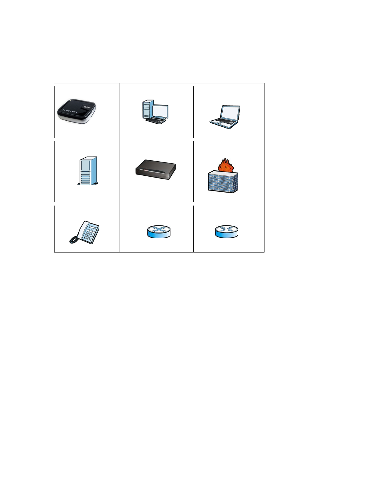
Icons Used in Figures
Figures in this User’s Guide may use the following generic icons. The MWR102 icon is not an
exact representation of your device.
MWR102
Server
Telephone
Computer
Modem
Switch
Notebook
computer
Firewall
Router
6
Page 7

Safety Warnings
• Do NOT use this product near water, for example, in a wet basement or near a swimming pool.
• Do not leave the device exposed to a heat source or in a high-temperature location such as in
the sun or in an unattended vehicle. To prevent damage, remove the device from the vehicle
or store it out of direct sunlight
• When storing the device for an extended time, store within the following temperature range:
from 32° to 77°F
• Do not operate the device beyond the range of 32° to 104° F
• Do not operate or store the device outside of the above temperature range
• Contact your local waste disposal department to dispose of the device/battery in accordance
with applicable local laws and regul ati ons.
• Do NOT expose your device to dampness, dust or corrosive liquids.
• Do Not keep the unit power on while putting it into suite case, closed box, luggage, computer
bag and any closed storage, do turn the device power off before storage.
• Do NOT store things on the device.
• Do NOT install, use, or service this device during a thunderstorm. There is a remote risk of
electric shock from lightning.
• Connect ONLY suitable accessories to the device.
• Do NOT open the device or unit. Opening or removing covers can expose you to dangerous
high voltage points or other risks. ONLY qualified service personnel should service or
disassemble this device. Please contact your vendor for further information.
• Make sure to connect the cables to the correct ports.
• Pl ace connecting cables carefully so that no one will step on them or stumble over them.
• Always disconnect all cables from this device before servicing or disassembling.
• Use ONLY power adaptor or cord provided by the manufacturer for your device.
• Connect the power adaptor or cord to the right supply voltage (for example, 110V AC in North
America or 230V AC in Europe).
• Do NOT allow anything to rest on the power adaptor or cord and do NOT place the product
where anyone can walk on the power adaptor or cord.
• Do NOT use the device if the power adaptor or cord is damaged as it might cause
electrocution.
• If the power adaptor or cord is damaged, remove it from the power outlet.
• Do NOT attempt to repair the power adaptor or cord. Contact your local vendor to order a new
one.
• Do not use the device outside, and make sure all the connections are indoors. There is a
remote risk of electric shock from lightning.
• Do NOT obstruct the device ventilation slots, as insufficient airflow may harm your device.
• Antenna Warning! This device meets ETSI and FCC certification requirements when using the
included antenna(s). Only use the included antenna(s).
• If you wall mount your device, make sure that no electrical lines, gas or water pipes will be
damaged.
Battery Warnings
Please follow the safety guidelines described in the safety warning and battery warning. Failing to
do so may shorten the lifespan of the internal lithium ion battery or may present a risk of
damage to the unit, fire, chemical burn, electrolyte leak and/or injury.
7
Page 8

• Do not leave unit exposed to a heat source or in a location that may become hot, such as a
parked vehicle or in direct sunlight. Do not leave in a glove box, trunk or other location that may
become hot.
• Do not puncture or incinerate the device or battery.
• When/if you dispose of the battery, be certain to follow ordinances from local waste disposal
agencies.
• Keep the battery away from small children or pets
• Never use a knife, screwdriver or other sharp object to remove the battery.
• Do not attempt to open the battery.
• Use only the provided recharger to rech arge the battery.
• Only replace the battery with the correct replacement battery. Failure to do so may result in fire
or explosion. Contac ZyXEL to obtain the correct replacement battery.
Your product is marked with this symbol, which is known as the WEEE mark. WEEE stands for
Waste Electronics and Electrical Equipment. It means that used electrical and electronic products
should not be mixed with general waste. Used electrical and electronic equipment should be
treated separately.
8
Page 9

Table of Contents
About This User's Guide .................................................................................................. 3
Document Conventions ................................................................................................... 5
Safety Warnings .............................................................................................................. 7
Part I: Introduction .................................................................................................. 13
1 Getting to Know Your MWR102 ............................................................................. 14
1.1 Overview ........................................................................................................ 14
1.2 Applications ................................................................................................... 14
1.3 Good Habits for Managing the MWR102 ........................................................ 15
1.4 The Front Panel ................................................................................................. 15
1.5 The Rear Panel ................................................................................................. 16
2 Web-Based Management ....................................................................................... 17
2.1 Overview ........................................................................................................ 17
2.2 Accessing the Web-Based Management Interface ......................................... 17
2.3 Resetting the MWR102 .............................................................................. 18
3 MWR102 Modes .................................................................................................... 19
3.1 Overview ........................................................................................................ 19
4 Router Mode .......................................................................................................... 20
4.1 Overview ........................................................................................................ 20
4.2 What You Can Do .......................................................................................... 20
5 Access Point Mode ................................................................................................ 23
5.1 Overview ........................................................................................................ 23
5.2 What You Can Do .......................................................................................... 23
5.3 AP Mode Status Screen ................................................................................. 24
5.4 LAN Screen ................................................................................................... 27
6 Tutorials ................................................................................................................. 29
9
Page 10

6.1 Overview ........................................................................................................ 29
6.2 Connecting to Internet from an Access Point ................................................... 30
6.3 Configuring Wireless Security Using WPS ....................................................... 30
6.4 Enabling and Configuring Wireless Security (No WPS) .............................. 32
Part II: Wireless ........................................................................................................ 35
7 Wireless ................................................................................................................. 36
7.1 Overview ........................................................................................................ 36
7.2 What You Can Do .......................................................................................... 36
7.3 What You Should Know ................................................................................. 36
7.4 General Wireless LAN Screen ....................................................................... 39
7.5 Wireless LAN Advanced Settings ................................................................... 40
7.6 Security .......................................................................................................... 42
7.7 Access Control ............................................................................................... 45
7.8 WPS Sc reen .................................................................................................. 47
7.9 Wireless Site Survey (AP Mode Only) ............................................................ 48
8 Network Settings .................................................................................................... 50
8.1 Overview ........................................................................................................ 50
8.2 What You Can Do .......................................................................................... 50
8.3 What You Need To Know............................................................................... 51
8.4 LAN Interface ................................................................................................. 52
8.5 WAN Interface ............................................................................................... 54
Part III: Security ........................................................................................................... 56
9 MAC Filtering ......................................................................................................... 57
9.1 Overview ........................................................................................................ 57
9.2 What You Can Do .......................................................................................... 57
9.3 What You Need To Know............................................................................... 57
9.4 MAC Filtering ................................................................................................. 58
Part IV: Management ................................................................................................... 59
10
Page 11

10 Status ................................................................................................................ 60
10.1 Overview .................................................................................................... 60
10.2 What You Can Do ...................................................................................... 60
10.3 Status Screen ............................................................................................ 60
11 Statistics ............................................................................................................ 63
11.1 Overview .................................................................................................... 63
11.2 Statistics Screen ........................................................................................ 63
12 Log .................................................................................................................... 65
12.1 Overview .................................................................................................... 65
12.2 Log Screen ................................................................................................ 65
13 Upgrade Firmware ............................................................................................. 67
13.1 Overview .................................................................................................... 67
13.2 Upgrade Firmware Screen ......................................................................... 67
14.1 Overview .................................................................................................... 69
14.2 What You Can Do ...................................................................................... 69
14.3 Save/Reload Settings Screen .................................................................... 69
15 Password ........................................................................................................... 72
15.1 Overview .................................................................................................... 72
15.2 Password Screen ....................................................................................... 72
Part V: Troubleshooting ............................................................................................. 74
16 Troubleshooting ................................................................................................. 75
16.1 Overview .................................................................................................... 75
16.2 Power, Hardware Connections, and LEDs ................................................. 75
16.3 MWR102 Access and Login ....................................................................... 76
16.4 Internet Access .......................................................................................... 77
16.5 Resetting MWR102 to Factory Defaults ..................................................... 79
16.6 Wireless Router/AP Troubleshooting ......................................................... 79
17 Product Specifications ....................................................................................... 81
11
Page 12

Appendix A: Pop-up Windows, JavaScripts and Java Permissions ............................... 85
Appendix B: IP Addresses and Subnetting .................................................................... 93
Appendix C: Setting up Your Computer’s IP Address .................................................. 105
Appendix D: Wireless LANs ........................................................................................ 127
Appendix E: Common Services ................................................................................... 141
Appendix F: Legal Information ..................................................................................... 146
Appendix G: Open Source Licenses ............................................................................ 150
12
Page 13

Part I: Introduction
13
Page 14

1 Getting to Know Your
MWR102
1.1 Overview
The MWR102 is a mobile wireless router with 1T1R MIMO technology. It complies with
IEEE 802.11n standards, with Wireless N data rates of up to 150 Mbps, and IEEE
802.11b/g with Wireless B/G data rates of 54 Mbps. It is also backward compatable with
all 11/54 Mbps wireless (802.11b/g) products.
The router allows multiple users to share one broadband connection, as well as secures
your private network. LAN users can share files, printers, or play network games all at
high speeds over the same network.
The MWR102 supports advanced security encryption: WPA, WPA2, open shared key,
and pair-wise key authentication services, giving you vital network security. Moreover,
this router supports energy efficient Ethernet and saves power.
1.2 Applications
You can create the following networks using the MWR102:
• Wired. You can connect a network device via the Ethernet port of the MWR102 so that they
can communicate with each other and access the Internet.
• Wireless. Wireless clients can connect to the MWR102 to access network resources.
• Land line WAN. Connect to a broadband modem/router for Internet access.
14
Page 15
1.3 Good Habits for Managing the MWR102
There is no device linked to the corresponding port or
There are devices linked to the corresponding ports but
no data transmitted or received.
Do the following things regularly to make the MWR102 more secure and to manage the MWR102
more effectively.
• Change the password. Use a password that’s not easy to guess and that consists of different
types of characters, such as numbers and letters.
• Write down the password and put it in a safe place.
• Back up the configuration (and make sure you know how to restore it). Restoring an earlier
working configuration may be useful if the device becomes unstable or even crashes. If you
forget your password, you will have to reset the MWR102 to its factory default settings. If you
backed up an earlier configuration file, you would not have to totally re-configure the MWR102.
You could simply restore your last configuration.
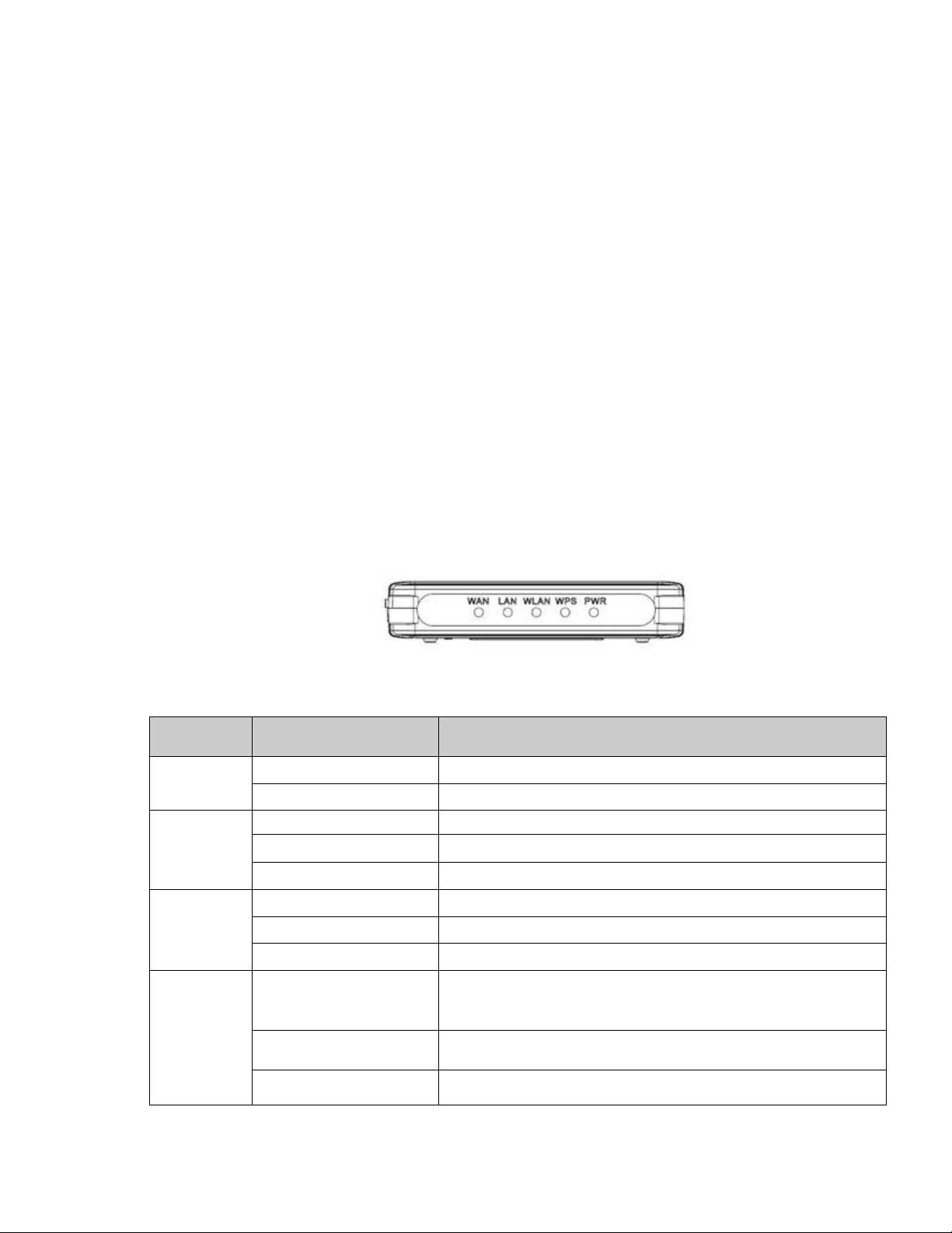
1.4 The Front Panel
Figure 1 The front panel of the Wireless Router
Table 1 Front Panel LEDs
Name Status Indication
PWR
Blink green one time System reboot
WPS
WLAN
WAN /
LAN
Green Power on
Dark Power off
Blink green WPS connecting
Dark System stable
Off The wireless function is disabled.
Flashing The wireless function is enabled.
Flashing fast Sending or receiving data over wireless.
Off
On
Flashing Sending or receiving data over corresponding port.
the connection is dropping off.
15
Page 16
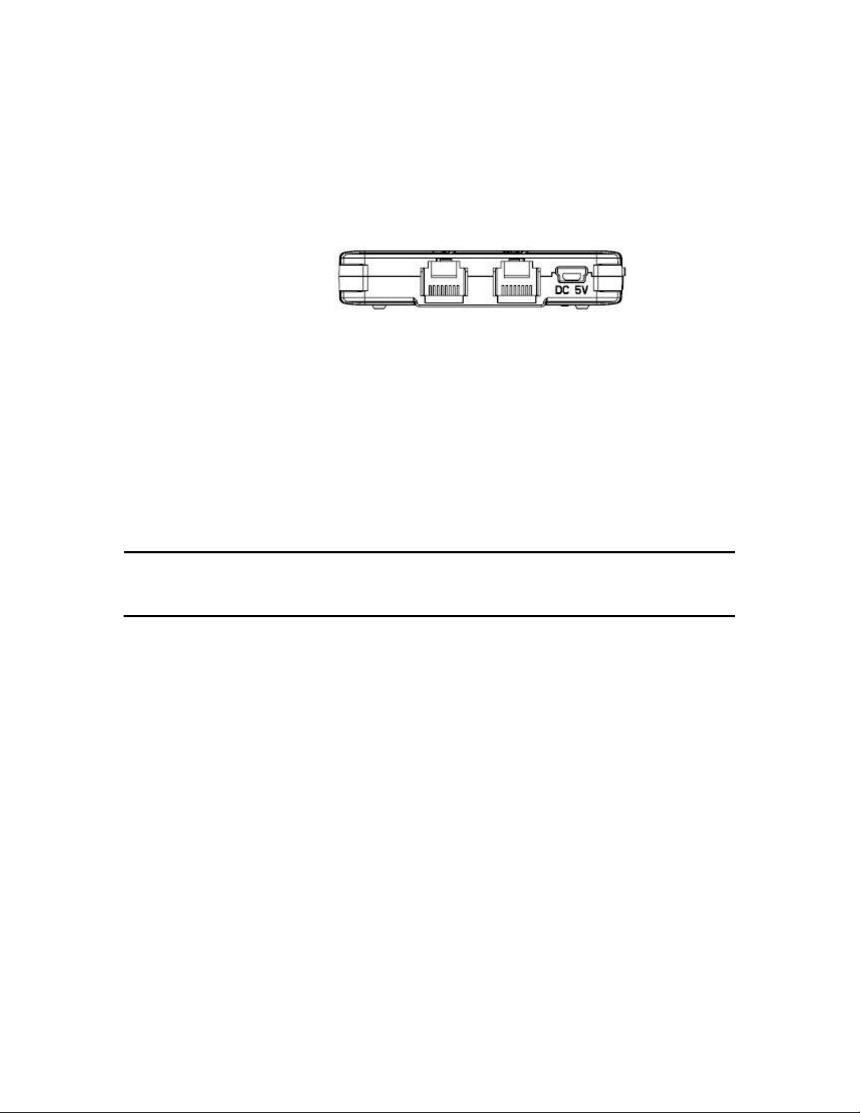
1.5 The Rear Panel
Figure 2 The rear panel of the Wireless Router.
LAN: Through this port, you can connect the router to your PCs and the other
Ethernet network devices.
WAN: T his WAN port is where you will connect the cable/DSL Modem, or Ethernet.
DC IN: Plug the end of the cable firmly into the rear panel of the router, and plug
the other end into a USB outlet to power the system.
WPS/Reset Button: Located on the underside of the device. Click this button to
start PBC configuration method for easy WPS setup.Hold the reset button for 5
seconds or more to reset the system to factory defaults. The system will then
reboot, and approximately 60 seconds later will be ready for further use. The reboot
process cannot be interrupted by powering off the device, or the unit will fail. Before
performing the reset process, ensure the system will be able to finish rebooting!
Warning: Incomplete factory setting recovery procedure will cause the Wireless
Router to malfunction! If you are in this situation, do not try to repair it by
yourself. Consult your local distributor for help!
16
Page 17

2 Web-Based Management
2.1 Overview
This chapter describes how to access the MWR102 Web-Based Management Interface and
provides an overview of its screens.
The Web-Based Management Interface is an HTML-based management interface that allows
easy setup and management of the MWR102 via Internet browser. Use Internet Explorer 7.0 and
later or Firefox 3.0 and later versions or Safari 4.0 or later versions. The recommended screen
resolution is 1024 by 768 pixels or higher. In order to use the Web-Based Management Interface
you need to allow:
• Web browser pop-up windows from your device. Web pop-up blocking is enabled by default in
Windows XP SP (Service Pack) 2.
• JavaScripts (enabled by default).
• Java permissions (enabled by default).
Refer to the Troubleshooting chapter (Chapter 16) to see how to make sure these functions are
allowed in Internet Explorer.
2.2 Accessing the Web-Based Man agement
Interface
1 Make sure your MWR102 hardware is properly connected and prepare your computer or
computer network to connect to the MWR102 (refer to the Quick Start Guide).
2 Launch your web browser.
3 Type "http://192.168.100.1" as the website address. Your computer must be in the same
subnet in order to access this website addres s.
2.2.1 Login Screen
The Web-Based Management Interface initially displays the following login screen.
17
Page 18
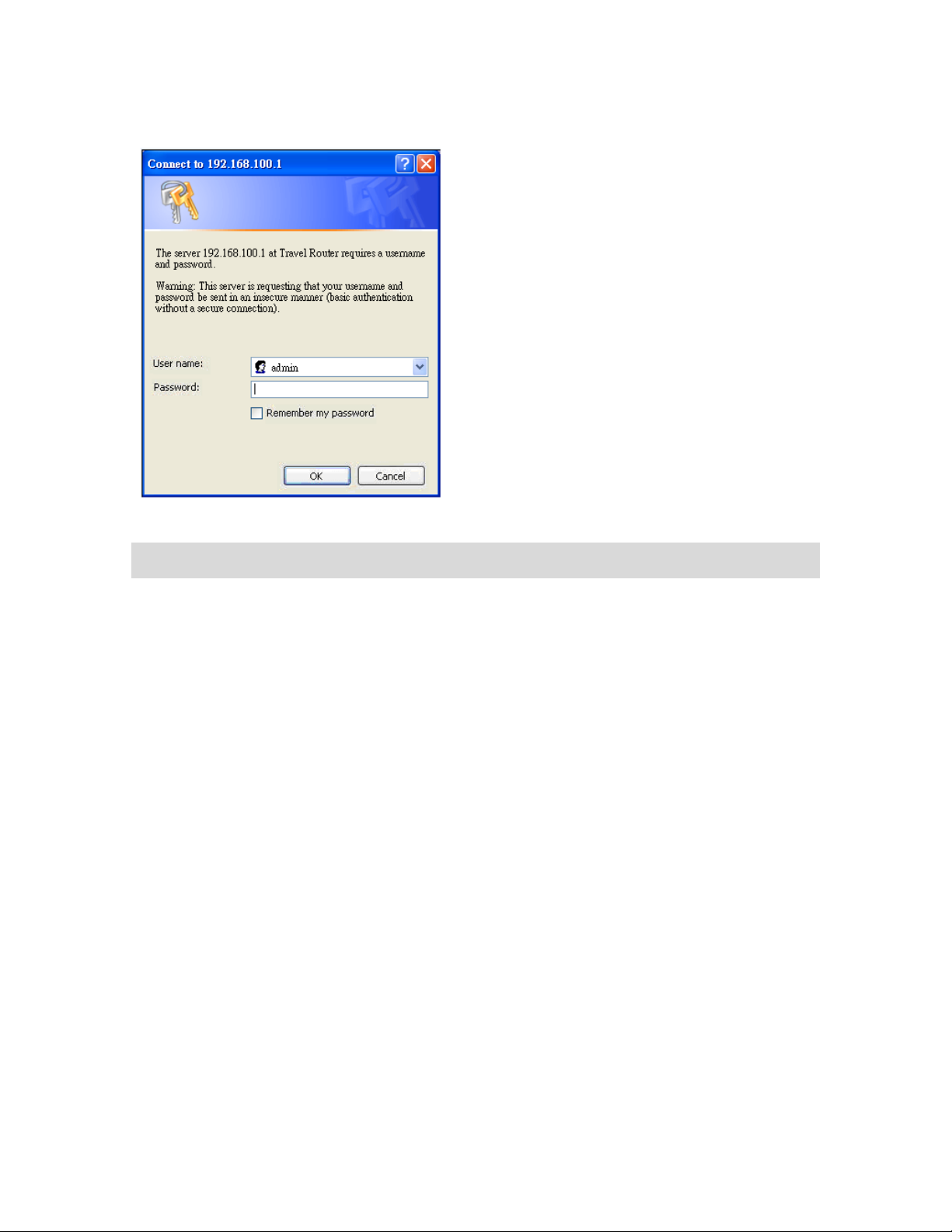
Figure 3 Login Screen
LABEL
DESCRIPTION
User Name
Type “admin” (default) as the User name.
Password
Type “1234” (default) as the password.
The following table describes the labels in this screen.
2.3 Resetting the MWR102
If you forget your password or IP address, or you cannot access the Web-Based Management
Interface, you will need to use the RESET button at the back of the MWR102 to reload the
factory-default configuration file. This means that you will lose all configurations that you had
previously saved, the password will be reset to “1234” and the IP address will be reset to
“192.168.100.1”.
2.3.1 Procedure to Use the Reset Button
1 Make sure the power LED is on.
2 Press the RESET button for longer than one second to restart/reboot the MWR102.
3 Press the RESET button for longer than five seconds to set the MWR102 back to its factory-
default configurations. The Power LED will start to blink to indicate that the default configuration is
being loaded.
18
Page 19

3 MWR102 Modes
3.1 Overview
This chapter introduces the different modes available on your MWR102.
3.1.1 Device Modes
This refers to the operating mode of the MWR102, which can act as a:
• Router. This is the default device mode of the MWR102. Use this mode to connect the local
network to another network, like the Internet.
• Access Point. Use this mode if you want to extend your network by allowing network devices to
connect to the MWR102 wirelessly. Go to AP view the Status screen in this mode.
19
Page 20
4 Router Mode
4.1 Overview
The MWR102 is set to router mode by default. Routers are used to connect the local
network to another network (for example, the Internet).
4.2 What You Can Do
Use the Status screen to view read-only information about your MWR102.
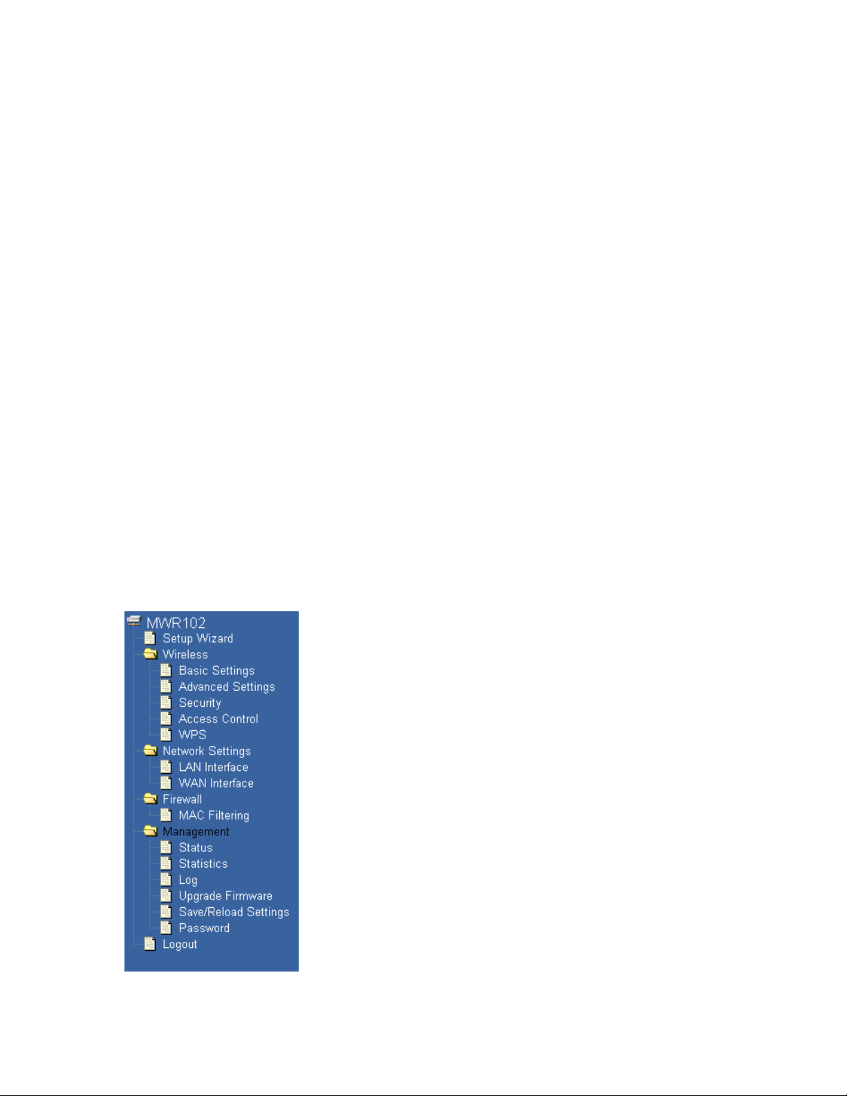
4.2.1 Navigation Panel
Use the sub-menus on the navigation panel to configure MWR102 features.
Figure 4 Navigation Panel
20
Page 21

Table 2 Navigation Panel: Router Mode
screen allows you to configure the parameters for your Local Area
The following table describes the sub-menus.
LINK FUNCTION
Setup Wizard
Wireless
Basic Settings Use this screen to change the basic wireless settings of the MWR102
Advanced Settings
Security Use this screen to change Wireless Security settings.
Access Control
WPS
Network Settings
This screen guides you through the setup of the MWR102.
Use this screen to configure advanced wireless settings
This page allows control over what devices are allowed to access the
router.
This screen allows you to change the Wi-Fi Protected Setup settings
for the MWR102
LAN Interface
WAN Interface
Firewall
MAC Filtering
Management
This
Network.
This screen allows you to configure WAN setting s.
This screen allows you to deny access to specific devices on your
network.
21
Page 22

Status Shows the current status and basic settings of the travel router
Password
Statistics Shows packet counts for wired and wireless Ethernet connections.
Log Set remote log server parameters and view the system log.
Upgrade Firmware
Upgrade the travel router firmware.
Save/Reload
Settings
Logout
Save the current settings to a backup file, or reload the setting from a
previously saved file.
Set or change the travel router ADMINISTRATOR user name and
password.
22
Page 23

5 Access Point Mode
5.1 Overview
Use your MWR102 as an access point (AP) if you already have a router or gateway on your
network. In this mode your MWR102 bridges a wired network (LAN) and wireless LAN (WLAN) in
the same subnet.
5.2 What You Can Do
• Use the Status screen to view read-only information about your MWR102.
• Use the LAN screen to set the IP address for your MWR102 acting as an access point.
5.2.1 Setting your MWR102 to AP Mode
1 Flip the switch on the side of the device from “Router” to “AP.”
5.2.2 Accessing the Web-Based Management Interface
in Access Point Mode
Log in to the Web-Based Management Interface in Access Point mode, do the following:
1 Connect your computer to the LAN port of the MWR102.
2 The default IP address of the MWR102 is “192.168.100.1”. In this case, your computer
must have an IP address in the range between “192.168.100.2” and “192.168.100.254”.
3 Click Start > Run on your computer in Windows. Type “cmd” in the dialog box. Enter
“ipconfig” to show your computer’s IP address. If your computer’s IP address is not in the
correct range then see Appendix C for information on changing your computer’s IP
address.
4 After you’ve set your computer’s IP address, open a web browser such as Internet
Explorer and type “192.168.100.1” as the web address in your web browser.
23
Page 24
5.2.3 Configuring your WLAN and Maintenance
Table 3 Status Screen: Router Mode
Settings
The configuration of wireless and maintenance settings in Access Point mode is the same as for
Router Mode.
• See Chapter 7 for information on the configuring your wireless network.
5.3 AP Mode Status Screen
Click Management > Status to open the Status screen
LABEL DESCRIPTION
System Information
Uptime This is the total time the MWR102 has been on.
Firmware Version This is current firmware version.
Firmware Build Time This is the date/time the current version of the firmware was released.
Operation Mode
Wireless Local Network
This is the device mode to which the MWR102 is set – AP Mode.
We provide six modes for your selection: 2.4GHz ( B ), 2.4 GHz
(G), 2.4 GHz (N), 2.4GHz (B+G), 2.4 GHz (G+N), 2.4 GHz
Network Band
SSID (Name)
Channel Number
(B+G+N).
You may select one type of network band from the dropdown menu.
Shows the current name of your wireless network.
This shows the channel number the MWR102 is currently using over Wireless LAN.
24
Page 25

Encryption
This shows the level of wireless security the MWR102 is currently using.
BSSID
Associated Clients
Local Network
Router IP Address
Subnet Mask
DHCP
Auto IP Address
Diversion
Local MAC Address
This displays the MAC address of the wireless device.
Displays the number of clients currently associated to the MWR102
Displays the IP address designated to the MWR102 by your router.
Shows what subnet mask the MWR102 is on.
This shows the LAN port’s DHCP role - Server or None.
Click the drop down list, you may select “Enabled” to divert the IP Address
automatically or select “Disabled” to ban it. When Enabled e, the system will
automatically detect conflicts in the WAN and LAN IP. If there are conflicts, the LAN
IP and LAN DHCP Range will automatically jump to next subnet to avoid conflicts.
This is the MAC address of your MWR102
5.3.1 Navigation Panel
Use the menu in the navigation panel to configure MWR102 features in Access Point mode.
The following screen and table show the features you can configure in Access Point mode.
25
Page 26
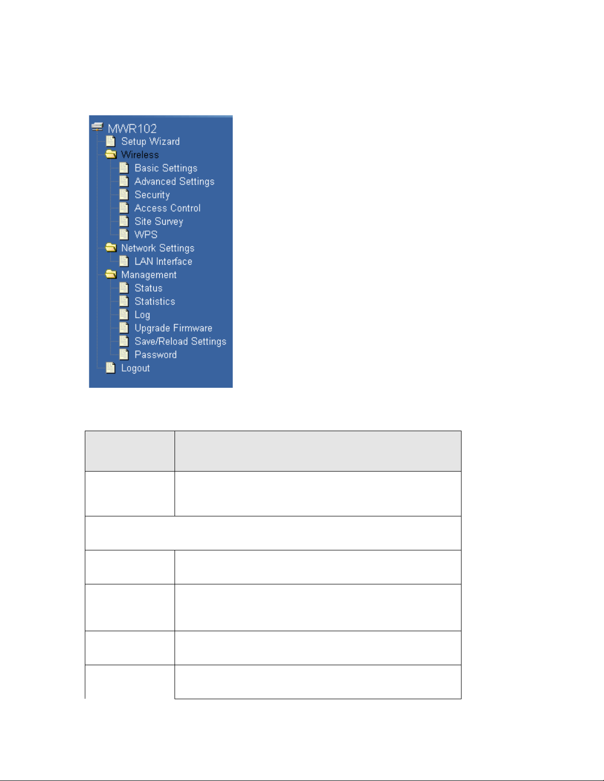
Table 4 Navigation Panel: Router Mode
Figure 5 Navigation Panel
The following table describes the sub-menus.
LINK FUNCTION
Setup Wizard
Wireless
Basic Settings Use this screen to change the basic wireless settings of the MWR102
Advanced Settings
Security Use this screen to change Wireless Security settings.
This screen guides you through the setup of the MWR102.
Use this screen to configure advanced wireless settings
Access Control This page allows control over what devices are allowed to access the
26
Page 27

router.
This screen allows you to configure the parameters for your Local Area
Password
Site Survey
WPS
Network Settings
LAN Interface
Management
Status Shows the current status and basic settings of the travel router
Statistics Shows packet counts for wired and wireless Ethernet connections.
Log Set remote log server parameters and view the system log.
This page provides a tool to scan the wireless network for
nearby routers and APs.
This screen allows you to change the Wi-Fi Protected Setup settings
for the MWR102
Network.
Upgrade Firmware
Upgrade the travel router firmware.
Save/Reload
Settings
Logout
Save the current settings to a backup file, or reload the setting from a
previously saved file.
Set or change the travel router ADMINISTRATOR user name and
password.
5.4 LAN Screen
Use this section to configure your LAN settings while in Access Point mode.
Click Network Settings > LAN Interface to see the screen below.
27
Page 28
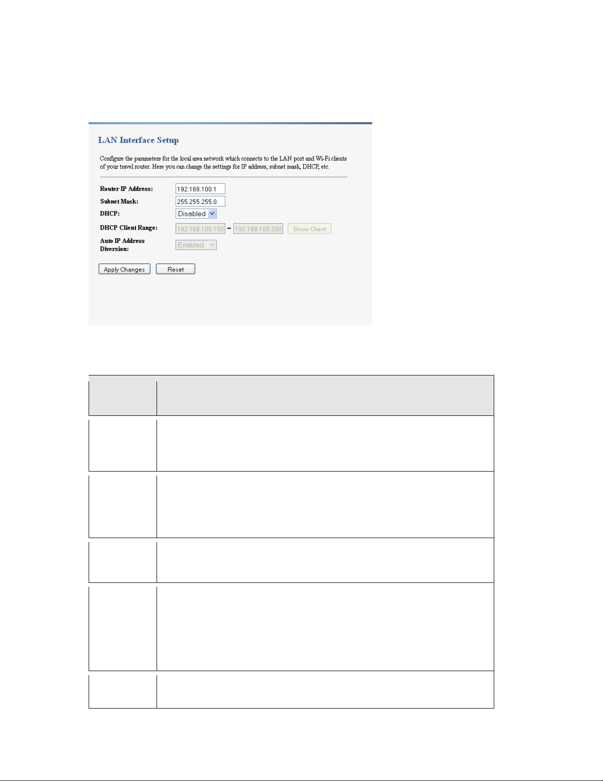
Note: If you change the IP address of the MWR102 in the screen below, you will need to
automatically or select “Disabled” to ban it. When Enabled e, the system will
log into the MWR102 again using the new IP address.
Figure 6 Network Settings > LAN Interface
The table below describes the labels in the screen.
Table 5 Network Settings > LAN Interface
LABEL DESCRIPTION
Router IP
Address
Subnet Mask
DHCP
DHCP
Client
Range
Type the IP address in dotted decimal notation. The default setting is
192.168.100.2. If you change the IP address you will have to log in again with the
new IP address.
The subnet mask specifies the network number portion of an IP address. Your
MWR102 will automatically calculate the subnet mask based on the IP address that
you assign. Unless you are implementing subnett ing, use the subnet mas k
computed by the MWR102.
DHCP stands for Dynamic Host Configuration Protocol. It is a protocol for
assigning dynamic IP addresses “auto matically”.
This field asks you to specify the DHCP Client IP address range (default
100~200). You can also click the “Show Client” button to list those connected
DHCP clients.
Note: In Router mode, the DHCP Server is enabled by default. However, in AP
mode, the DHCP Server disabled by default.
Auto IP
Address
Click the drop down list, you may select “Enabled” to divert the IP Address
28
Page 29

Diversion
automatically detect conflicts in the WAN and LAN IP. If there are conflicts, the
LAN IP and LAN DHCP Range will automatically jump to next subnet to avoid
•
•
conflicts.
6 Tutorials
6.1 Overview
This chapter provides tutorials for your MWR102 as follows:
• Connecting to the Internet from an Access Point
• Configuring Wireless Security Using WPS
•
Enabling and configuring wireless securi ty
6.1.1 DSL Modem
If your internet connection comes from a DSL modem you will want to follow these steps to best prepare
your modem to connect with the MWR102.
1) Contact your ISP (Internet Service Provider) and ask them to help you “bridge” your DSL modem.
2) Find out from your ISP what the “PPPoE Username and Password” are for your Internet connection.
3) Once the DSL modem has been bridged, connect it (by Ethernet cord) to the WAN port of the MWR102.
4) Open your browser and log into the MWR102. Click on Network Settings > WAN Interface, for the WAN
Access Type select “PPPoE” and enter your PPPoE “Username and Password.”
6.1.2 Cable Modem
Connect the cable modem to your MWR102 on the WAN port. Unplug the power to your
cable modem. Depending on your cable modem, it may also have a backup battery
inside. Remove this battery and completely power down the cable modem. Let it sit from
2 to 3 minutes and then reconnect the battery and power to the cable modem.
If the router is set with its default settings it should automatically connect to the Internet.
29
Page 30
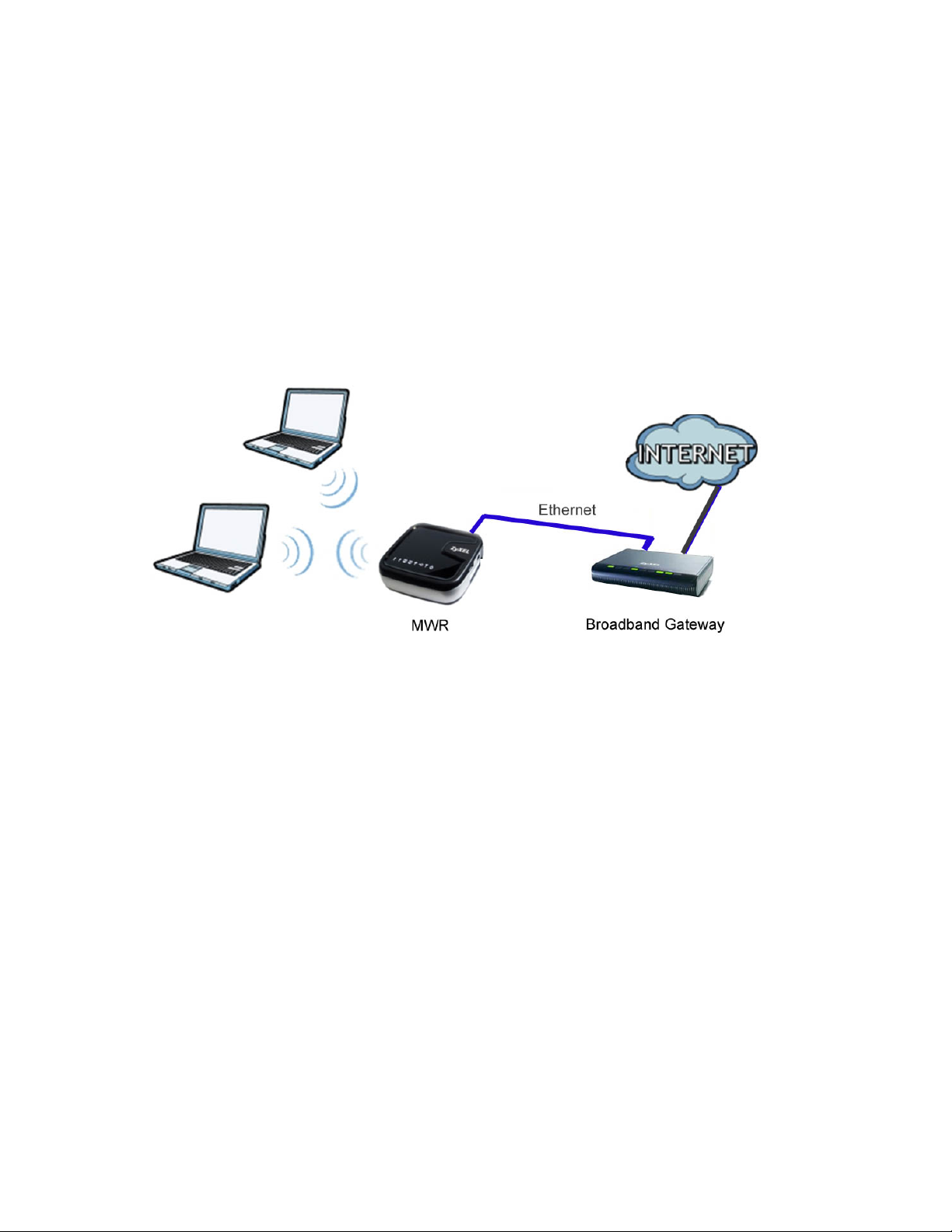
6.2 Connecting to Internet from an Access
Point
This section gives you an example of how to set up an access point (AP) and wireless client (a
notebook (B), in this example) for wireless communication. B can access the Internet through the
access point wirelessly. When the MWR is configured in AP mode, it has to connect to a
broadband gateway (wired or wireless router with broadband connection). Local computer(s) can
get IP via wireless connection passed by MWR from the broadband gateway, then gain Internet
access.
Figure 7 Wireless Access Point mode
6.3 Configuring Wireless Security Using
WPS
This section gives you an example of how to set up wireless network using WPS. This example
uses the MWR102 as the AP and NWD210N as the wireless client which connects to a notebook.
Note: The wireless client must be a WPS-aware device (for example, a WPS USB
adapter or PCI card).
There are two WPS methods for creating a secure connection. This tutorial shows you how to do
both.
• Push Button Configuration (PBC) - create a secure wireless network simply by pressing a
button. This is the easier method.
• PIN Configuration - create a secure wireless network simply by entering a wireless client's PIN
(Personal Identification Number) in the MWR102’s interface. This is the more secure method,
since one device can authenticate the other.
30
Page 31

6.3.1 Push Button Configuration (PBC)
1 Make sure that your MWR102 is turned on and that it is within range of your computer.
2 Make sure that you have installed the wireless client (this example uses the NWD210N)
driver and utility in your notebook.
3 In the wireless client utility, find the WPS settings. Enable WPS and press the WPS
button (Start or WPS button)
4 Log into MWR102’s Web-Based Management Interface and press the Start PBC button
in the Wireless > WPS screen.
Note: Your MWR102 has a WPS button located on its bottom panel, as well as a WPS
button in its configuration utility. Both buttons have exactly the same function; you can
use one or the other.
Note: It doesn’t matter which button is pressed first. You must press the second button
within two minutes of pressing the first one.
The MWR102 sends the proper configuration settings to the wireless client. This may take up to
two minutes. Then the wireless client is able to communicate with the MWR102 securely.
6.3.2 PIN Configuration
When you use the PIN configuration method, you need to use both MWR102’s configuration
interface and the client’s utilities.
1 Launch your wireless client’s configuration utility. Go to the WPS settings and select the
PIN method to get a PIN number.
2 Enter the PIN number to the PIN field in the Wireless > WPS screen on the MWR102.
3 Click Start buttons (or button next to the PIN field) on both the wireless client utility
screen and the MWR102’s WPS Station screen within two minutes.
The MWR102 authenticates the wireless client and sends the proper configuration settings to the
wireless client. This may take up to two minutes. Then the wireless client is able to communicate
with the MWR102 securely.
31
Page 32

6.4 Enabling and Configuring Wireless
Security (No WPS)
Follow the steps below to configure the wireless settings on your MWR102.
The instructions require that your hardware is connected (see the Quick Start Guide) and you are
logged into the Web-Based Management Interface through your LAN connection.
1 Open the Wireless > Security scr een in the AP ’s Web-Based Management Interface.
2 Choose a Pre-Shared Key format. (Passphrase or Hex)
3 Enter your desired key, then click the Apply Changes button.
Figure 8 Tutorial: Wireless > Security
6.5 Configure Your Notebook
Note: We use the ZyXEL M-302 wireless adapter utility screens as an example for the
wireless client. The screens may vary for different models.
1. The MWR102 supports IEEE 802.11b, IEEE 802.11g and IEEE 802.11n wireless
clients. Make sure that your notebook or computer’s wireless adapter supports one of
these standards.
32
Page 33

2. Wireless adapters come with software sometimes called a “utility” that you install on
your computer. See your wireless adapter’s User’s Guide for information on how to
do that.
3. After you’ve installed the utility, open it. If you cannot see your utility’s icon on your
screen, go to Start > Programs and click on your utility in the list of programs that
appears. The utility displays a list of APs within range, as shown in the example
screen below.
4. Select the MWR102’s SSID and click Connect.
Figure 9 Connecting a Wireless Client to a Wireless Network
5. Select WPA-PSK and type the security key in the following screen. Click Next.
Figure 10 Security Settings
6. The Confirm Save window appears. Check your settings and click Save to continue.
33
Page 34

Figure 11 Confirm Save
7. Check the status of your wireless connection in the screen below. If your wireless
connection is weak or you have no connection, see the Troubleshooting section of
this User’s Guide.
Figure 12 Link Status
If your connection is successful, open your Internet browser and enter http://us.zyxel.com or the
URL of any other web site in the address bar. If you are able to access the web site, your wireless
connection is successf ull y configured.
34
Page 35

Part II: Wireless
35
Page 36

7 Wireless
7.1 Overview
This chapter discusses how to configure the wireless network settings in your MWR102. See the
appendices for more detailed information about wireless networks.
7.2 What You Can Do
• Use the Basic Settings screen to enable the Wireless LAN, enter the SSID and select the
channel width.
• Use the Advanced Settings screen to set RF output power and set the RTS Threshold.
• Use the Security screen to set encryption type and passphrase.
• Use the Access Control screen to whitelist and blacklist devices on your network.
• Use the WPS screen to quickly set up a wireless network with strong security, without having to
configure security settings manually.
7.3 What You Should Know
Every wireless network must follow these basic guidelines.
• Every wireless client in the same wireless network must use the same SSID.
The SSID is the name of the wireless network. It stands for Service Set IDentity.
• If two wireless networks overlap, they should use different channels.
Like radio stations or television channels, each wireless network uses a specific channel, or
frequency, to send and receive information.
• Every wireless client in the same wireless network must use security compatible with the AP.
Security stops unauthorized devices from using the wireless network. It can also protect the
information that is sent in the wireless network.
36
Page 37

7.3.1 Wireless Security Overview
The following sections introduce different types of wireless security you can set up in the wireless
network.
7.3.1.1 SSID
Normally, the AP acts like a beacon and regularly broadcasts the SSID in the area. You can hide
the SSID instead, in which case the AP does not broadcast the SSID. In addition, you should
change the default SSID to something that is difficult to guess.
This type of security is fairly weak, however, because there are ways for unauthorized devices to
get the SSID. In addition, unauthorized devices can still see the information that is sent in the
wireless network.
7.3.1.2 MAC Address Filter
Every wireless client has a unique identification number, called a MAC address.1 A MAC address
is usually written using twelve hexadecimal characters
00:A0:C5:00:00:02. To get the MAC address for each wireless client, see the appropriate User’s
Guide or other documentation.
You can use the MAC address filter to tell the AP which wireless clients are allowed or not
allowed to use the wireless network. If a wireless client is allowed to use the wireless network, it
still has to have the correct settings (SSID, channel, and security). If a wireless client is not
allowed to use the wireless network, it does not matter if it has the correct settings.
This type of security does not protect the information that is sent in the wireless network.
Furthermore, there are ways for unauthorized devices to get the MAC address of an authorized
wireless client. Then, they can use that MAC address to use the wireless network.
2
; for example, 00A0C5000002 or
7.3.1.3 Encryption
Wireless networks can use encryption to protect the information that is sent in the wireless
network. Encryption is like a secret code. If you do not know the secret code, you cannot
understand the message.
The types of encryption you can choose depend on the type of user authentication.
1
Some wireless devices, such as scanners, can detect wireless networks but cannot use wireless networks. These
kinds of wireless devices might not have MAC addresses.
2
Hexadecimal characters are 0, 1, 2, 3, 4, 5, 6, 7, 8, 9, A, B, C, D, E, and F.
37
Page 38

Table 6 Types of Encryption for
Each Type of Authentication
NO AUTHENTICATION
Weakest
Strongest
Usually, you should set up the strongest encryption that every wireless client in the wireless
network supports. Suppose the wireless network has two wireless clients. Device A only supports
WEP, and device B supports WEP and WPA-PSK. Therefore, you should set up WEP in the
wireless network.
No Security
WEP
WPA-Personal (TKIP)
WPA-Enterprise
WPA2-Personal (AES)
WPA2-Enterprise
Note: It is recommended that wireless networks use WPA-Personal/Enterprise or
stronger encryption. IEEE 802.1x and WEP encryption are better than none at all, but it
is still possible for unauthorized devices to figure out the original information pretty
quickly.
Many types of encryption use a key to protect the information in the wireless network. The longer
the key, the stronger the encryption. Every wireless client in the wireless network must have the
same key.
7.3.1.4 WPS
Wi-Fi Protected Setup (WPS) is an industry standard specification, defined by the Wi-Fi Alliance.
WPS allows you to quickly set up a wireless network with strong security, without having to
configure security settings manually. Depending on the devices in your network, you can either
press a button (on the device itself or in its configuration utility) or enter a PIN (Personal
Identification Number) in the devices. Then, they connect and set up a secure network by
themselves.
38
Page 39

7.4 General Wireless LAN Scr een
Table 7 Wireless > Basic Settings
Use this screen to enable the Wireless LAN, enter the SSID and select the channel.
Note: If you are configuring the MWR102 from a computer connected to the wireless LAN
and you change the MWR102’s SSID, channel or security settings, you will lose your
wireless connection when you press Apply to confirm. You must then change the
wireless settings of your computer to match the MWR102’s new settings.
Click Wireless > Basic Settings to open.
Figure 13 Wireless > Basic Settings
The following table describes the general wireless LAN labels in this screen.
LABEL DESCRIPTION
Wireless Basic Settings
39
Page 40

Network Band
Channel Width
Allows you to choose between Wireless B/G/N functionality.
Allows you to choose between the 20MHz and 40MHz channel.
Channel
Number
Country
Broadcast
SSID
Associated
Clients
This displays the channel the MWR102 is currently using.
Allows you to set your country.
Set whether or not the MWR102 is discoverable.
The Show Clients button shows all clients associated with the MWR102.
7.5 Wireless LAN Advanced S etti n gs
Use this screen to allow wireless advanced features, such as setting output power and the RTS
Threshold
Click Wireless > Advanced Settings. The screen appears as shown.
40
Page 41

Figure 14 Wireless > Advanced Settings
Table 8 Wireless > Advanced Settings
The following table describes the labels in this screen.
LABEL DESCRIPTION
The threshold (number of bytes) for the fragmentation boundary for directed
Fragmentation
Threshold
RTS Threshold
Beacon
Interval
messages. It is the maximum data fragment size that can be sent. Enter an even
number between 256 and 2346.
Data with its frame size larger than this value will perform the RTS (Request To
Send)/CTS (Clear To Send) handshake.
Enter a value between 0 and 2347.
Beacons are packets sent by an access point to synchronize a
wireless network. Specify a beacon interval value. Default (100ms) is
recommended.
Preamble
Type
The length of CRC blocks in the frames during the wireless
communication.
41
Page 42

Output Power Set the output power of the MWR102 in this field. If there is a high density of APs in
an area, decrease the output power of the MWR102 to reduce interference with
other APs. Select one of the following 100%, 70%, 50%, 35%, or 15%. See the
product specifications for more information on your MWR102’s output power.
Apply
Changes
Reset
Click Apply Changes to save your changes back to the MWR102.
Click Reset to reload the previous configuration for this screen.
7.6 Security
7.6.1 Disabling Security
Select Disable to allow wireless stations to communicate with the access points without any data
encryption.
Note: If you do not enable any wireless security on your MWR102, your network is
accessible to any wireless networking device that is within range.
Figure 15 Wireless > Security
42
Page 43

7.6.2 WEP Encryption
Table 9 Wireless > Security: WEP
This field specifies whether the wireless clients have to provide the WEP key to login
verification before communication between the wireless client and the ZyXEL Device
WEP encryption scrambles the data transmitted between the wireless stations and the access
points to keep network communications private. It encrypts unicast and multicast communications
in a network. Both the wireless stations and the access points must use the same WEP key.
In order to configure and enable WEP encryption, click Wireless > Security to display the
Security screen. Se lect WEP from the Encryption list.
Figure 16 Wireless > Security: WEP
The following table describes the wireless LAN security labels in this screen.
LABEL DESCRIPTION
Encryption
Authentication
Method
Select Static WEP to enable data encryption.
Select Open System, Auto, or Shared Key.
to the wireless client. Keep this setting at Auto unless you want to force a key
occurs.
Select Shared Key to force the clients to provide the WEP key prior to
communication.
43
Page 44

Key Length
Select 64-bit or 128-bit.
This dictates the length of the security key that the network is going to use.
Key Format
Encryption Key
Apply
Changes
Reset
Select ASCII (5 Characters) or Hex (10 Characters) from the dropdown menu.
Enter a Passphrase.
A passphrase functions like a password. In WEP security mode, it is further
converted by the MWR102 into a complicated string that is referred to as the “key”.
This key is requested from all devices wishing to connect to a wireless network.
Click Apply to save your changes back to the MWR102.
Click Reset to reload the previous configuration for this screen.
7.6.3 WPA-PSK/WPA2-PSK/WPA2-Mixed
Click Wireless > Security to display the Security screen. Selec t WPA-PSK, WPA2-PSK, or
WPA2-Mixed from the Security Mode list.
Figure 17 Wireless > Security: WPA-PSK/WPA2-PSK/WPA2-Mixed
44
Page 45

The following table describes the labels in this screen.
Table 10 Wireless > Security: WPA-PSK/WPA2-PSK/WPA2-Mixed
LABEL DESCRIPTION
Encryption
Pre-shared Key
Format
Pre-Shared Key
Apply Changes
Reset
Select WPA-PSK, WPA2-PSK or WPA2-Mixed to enable data encryption.
This field allows you to choose between a passphrase and HEX as your SreShared Key Format.
WPA-PSK/WPA2-PSK/WPA2-Mixed use a simple common password for
authentication.
Type a pre-shared key from 8 to 63 case-sensitiv e key boar d char a cter s.
Click Apply Changes to save your changes back to the MWR102.
Click Reset to reload the previous configuration for this screen.
7.7 Access Control
The Access Control screen allows you to configure the MWR102 to give exclusive access to
devices (Allow) or exclude devices from accessing the MWR102 (Deny). Every Ethernet device
has a unique MAC (Media Access Control) address. The MAC address is assigned at the factory
and consists of six pairs of hexadecimal characters, for example, 00:A0:C5:00:00:02. You need to
know the MAC address of the devices to configure this screen.
To change your MWR102’s MAC filter settings, click Wireless > Access Control. The screen
appears as shown.
45
Page 46

Figure 18 Wireless > Access Control
Table 11 Wireless > Access Control
The following table describes the labels in this menu.
LABEL DESCRIPTION
Wireless
Access
Control
Mode
MAC
Address
Comment Enter any notes about the device being black/whitelisted in this field.
Delete
Selected
Define whether entered MAC addresses will be whitelisted or blacklisted.
Enter the MAC addresses of the wireless station that are allowed or denied access to
the MWR102 in this field. Enter the MAC addresses in a valid MAC address format,
that is, six hexadecimal character pairs, for example, 12:34:56:78:9a:bc. Click Apply
Changes.
Delete single MAC addresses from the list.
Delete All Delete all MAC addresses from the list.
46
Page 47

Apply
Table 12 Network > Wireless LAN > WPS
Changes
Click Apply to save your changes back to the MWR102.
Reset
Click Reset to reload the previous configuration for this screen.
7.8 WPS Screen
Use this screen to enable/disable WPS, view or generate a new PIN number and check current
WPS status. To open this screen, click Wireless > WPS.
Figure 19 Wireless > WPS
The following table describes the labels in this screen.
LABEL DESCRIPTION
Wi-Fi Protected Setup
Disable WPS Select this to disable the WPS feature.
47
Page 48

Status
This displays Configured when the MWR102 has connected to a wireless
network using WPS. The current wireless and wireless security settings also
appear in the screen.
This displays Unconfigured if WPS is disabled and there are no wireless or
wireless security changes on the MWR102 or you click Reset to Unconfigured
to remove the configured wireless and wireless security settings.
Self-PIN Number
Reset to
Unconfigured
Push Button
Configuration
Current Key Info
Client PIN
number
Apply
Refresh
This displays a PIN number last time system generated. Click Generate to
generate a new PIN number.
This button is only available when the WPS status displays Configured.
Click this button to remove all configured wireless and wireless security settings
for WPS connections on the MWR102.
Press this button to begin the PBC process.
The authentication type, encryption type, and key are displayed here if security
settings are configured.
This is where the PIN is displayed when using PIN setup. To generate a PIN,
press the Start PIN button.
Click Apply to save your changes back to the MWR102.
Click Refresh to get this screen information afresh.
7.9 Wireless Site Survey (AP M o de On ly)
Use this screen to view nearby wireless networks. Go to Wirel ess > Si te Survey to open the
following screen.
Figure 20 Wireless > Site Survey
48
Page 49

The following table describes the labels in this screen.
Table 13 Wireless > Site Survey
LABEL DESCRIPTION
Wireless Site Survey
SSID This displays the Network Name (SSID) of the wireless networks close to you.
This displays the MAC address of the wireless device listed.
BSSID
Channel This displays the wireless channel used by the wireless network.
Type This displays the network type being used by the wireless network.
Encrypt This displays the encryption type used by the wireless network.
Signal This displays the strength of the wireless network signal.
49
Page 50

8 Network Settings
8.1 Overview
This chapter discusses the MWR102’s Network Settings screens. Use these screens to
configure your LAN and WAN settings.
A Local Area Network (LAN) is a shared communication system to which many computers are
attached. A LAN is a computer network limited to the immediate area, usually the same building
or floor of a building.
A WAN (Wide Area Network) connection is an outside connection to another network or the
Internet. It connects your private networks such as a LAN (Local Area Network) and other
networks, so that a computer in one location can communicate with computers in other locations.
Figure 21 LAN and WAN
8.2 What You Can Do
• Use the LAN Interface Setup screen to modify your router’s IP address, DHCP Settings, and
Subnet Mask
• Use the WAN Interface Setup screen to modify your DHCP access type (DHCP client, Static IP,
or PPoE), MTU Size, DNS Settings, and MAC address.
50
Page 51

8.3 What You Need To Know
The information in this section can help you configure the screens for your WAN and LAN
connections.
8.3.1 Configuring Your Internet Connection
The actual physical connection determines whether the MWR102 ports are LAN or WAN ports.
There are two separate IP networks, one inside the LAN network and the other outside the WAN
network as shown next.
Figure 22 LAN and WAN IP Addresses (implies wired WAN connection)
The LAN parameters of the MWR102 are preset in the factory with the following values:
• IP address of 192.168.100.1 with subnet mask of 255.255.255.0 (24 bits)
• DHCP server enabled with 32 client IP addresses starting from 192.168.100.33.
These parameters should work for the majority of installations. If your ISP gives you explicit DNS
server address(es), read the embedded Web-Based Management Interface help regarding what
fields need to be configured.
8.3.2 WAN MAC Address
The MAC address screen allows users to configure the WAN port's MAC address by either using
the factory default or cloning the MAC address from a computer on your LAN. Choose Factory
Default to select the factory assigned default MAC Address.
Otherwise, click Clone the computer's MAC address - IP Address and enter the IP address of
the computer on the LAN whose MAC you are cloning. Once it is successfully configured, the
address will be copied to configuration file. It is recommended that you clone the MAC address
prior to hooking up the WAN Port.
51
Page 52

8.4 LAN Interface
on the network must have the same subnet mask to
default. However, in AP mode, the DHCP Server disabled by
The LAN Interface Setup screen allows you to set up your LAN interface, the private IP
of your router’s LAN port, and the subnet mask of your LAN segment. Go to Network >
LAN Interface to access the following screen.
Figure 23 Network > LAN Interface
The following table describes the labels in this screen.
Table 14 Network > LAN Interface
Items
Router IP
Address
Subnet Mask
DHCP
DHCP Client
Range
Information
The IP of your Router LAN port (default 192.168.100.1).
Subnet Mask of you LAN (default 255.255.255.0). All devices
communicate on the network.
DHCP stands for Dynamic Host Configuration Protocol. It is a
protocol for assigning dynamic IP addresses “automatically”.
This field asks you to specify the DHCP Client IP address
range (default 100~200). You can also click the “Show Client”
button to list those connected DHCP clients.
Note: In Router mode, the DHCP Server is enabled by
52
Page 53

default.
Click the drop down list, you may select “Enabled” to divert
This button refreshes the list with the most recent
the IP Address automatically or select “Disabled” to ban it.
Auto IP Address
Diversion
When Enabled, the system will automatically detect conflicts
in the WAN and LAN IP. If there are conflicts, the LAN IP and
LAN DHCP Range will automatically jump to next subnet to
avoid conflicts.
8.4.1 Active DHCP Client List
This window pops up after clicking the Show Client button.
Figure 24 Network > LAN Interface > Show Client
The following table describes the labels in this screen.
Table 15 Network > LAN Interface > Show Client
Items
IP Address
MAC Address
Time Expired
Refresh
Close
Information
The IP of the connected client.
The MAC Address of the connected client.
The amount of seconds the client has been connected.
information.
Closes the Active DHCP Client T a b le.
53
Page 54

8.5 WAN Interface
The IP address provided by your Internet Service Provider
The Subnet Mask provided by your Internet Service Provider
This page allows users to configure WAN settings. You may select the Internet
connection type from the drop down list next to “WAN Access Type” and configure the
parameters for each mode. Go to Network Settings > WAN Interface to open the
following screen.
Figure 25 Network > WAN Interface
The following table describes the labels in this screen.
Table 16 Network > WAN Interface
Items
WAN Access Type
Internet IP Address
Subnet Mask
Default Gateway The Default Gateway provided by your Internet Service
Information
Select to access the WAN as Static, DHCP Client or PPPoE.
(ISP).
(ISP).
54
Page 55

Provider (ISP).
MTU Siz e
To Delete MAC Addresses you have added before, mark the
check box on the right hand and click “Delete Selected.” If you
Clone MAC Address
The Maximum packet size the router will transmit. Any
packet over the specified size will be chopped into a smaller
size before sending. Larger packet size will enhance
performance.
Enter the MTU number in the blank to set the limitation.
There are two ways to clone a MAC address.
One way is to directly input a MAC address into the text
box. To store a MAC address, click the 'Manual Add' button
and add it to the “History MAC Table. ” The second way is to
click the 'MAC Clone' button. This will copy the MAC
address from your network card.
Note: The 'History MAC Table' can save a maximum of three
MAC Addresses.
History MAC Table
want to delete all saved MAC Addresses, click “Delete All.”
55
Page 56

Part III:
MAC Filtering
Security
56
Page 57

9 MAC Filtering
9.1 Overview
This chapter shows you how to enable and configure MAC address filtering that allows your
MWR102 to permit and deny access to specific devices on your network.
Enable MAC Filtering to restrict the passage of certain types of data packets from your local
network to the Internet through the travel router. Use of such filters can be helpful in securing or
restricting your local network.
By default the firewall allows all traffic that originates from your LAN computers to go to all
networks.
9.2 What You Can Do
• Use the MAC Filtering screen to enable or disable MAC Filtering, and modify what devices are
restricted to the local network.
9.3 What You Need To Know
The MWR102’s MAC Filtering feature physically separates the LAN and the WAN of selected
devices, and acts as a secure gateway to keep selected devices from having access to the WAN.
The MWR102 is installed between the LAN and a broadband modem connecting to the Internet.
This allows it to act as a gateway for all data passing between the Internet and the LAN.
The MWR102 has one Ethernet WAN port and one Ethernet LAN port, which are used to
physically separate the network into two areas. The WAN (Wide Area Network) port attaches to
the broadband (cable or DSL) modem to the Internet.
The LAN (Local Area Network) port attaches to a network of computers. These computers will
have access to Internet services such as e-mail, FTP and the World Wide Web unless their MAC
address is blocked by the MWR102.
57
Page 58

9.4 MAC Filtering
ame of the device, reason for
Lists MAC Filter Settings you have added before. To delete
, reason for
This page allows users to restrict data from passing onto the internet from certain
devices. Go to Firewall > MAC Filtering to open the following screen.
Figure 26 Firewall > MAC Filtering
Table 17 Firewall > MAC Filtering
Items
Enable MAC
Filtering
MAC Address
Comment
Current Filter Table
Enable MAC
Filtering
MAC Address
Comment
Information
Mark to enable MAC Filtering, and clear to disable.
Fill in the MAC address of wireless stations you want to forbid
Internet access to.
Input any text to describe the n
filtering, etc.
settings on the list, click the check box next to the item and
click “Delete Selected.” If you want to delete all saved MAC
addresses, click “Delete All.”
Mark to enable MAC Filtering, and clear to disable.
Fill in the MAC address of wireless stations you want to forbid
Internet access to.
Input any text to describe the name of the device
filtering, etc.
58
Page 59

Part IV:
Management
Status
Statistics
Log
Upgrade Firmware
Save/Reload Settings
Password
59
Page 60

10 Status
10.1 Overview
This chapter discusses how to access and interpret information about the MWR102.
10.2 What You Can Do
• Use the Status screen to view the current status and basic settings of the device.
10.3 Status Screen
This information page shows the current status and basic settings of this device.
Click Management > Status to open the Status screen.
Figure 27 Management > Status
60
Page 61

Table 18
Management > Status
LABEL DESCRIPTION
System Information
Uptime This is the total time the MWR102 has been on.
Firmware Build Time This is the date/time the current version of the firmware was released.
Operation Mode
Wireless Local Network
Network Band
SSID (Name)
Channel Number
Encryption
BSSID
Associated Clients
Local Network
This is the device mode to which the MWR102 is set – Router Mode.
We provide six modes for your selection: 2.4GHz (B), 2.4 GHz (G), 2.4 GHz (N),
2.4GHz (B+G), 2.4 GHz (G+N), 2.4 GHz (B+G+N).
You may select one type of network band from the dropdow n menu.
Shows the current name of your wireless network.
This shows the channel number the MWR102 is currently using over Wireless LAN.
This shows the level of wireless security the MWR102 is currently using.
This displays the MAC address of the wireless device.
Displays the number of clients currently associated to the MWR102
Router IP Address
Subnet Mask
DHCP
Internet Connection
Connection Type
Displays the IP address designated to the MWR102 by your router.
Shows what subnet mask the MWR102 is on.
This shows the LAN port’s DHCP role - Server or None.
Shows connection type: Static, DHCP Client or PPPoE.
61
Page 62

Internet IP Address
The IP address provided by your Internet Service Provider (ISP).
Subnet Mask
Default Gateway
Internet MAC Address
The Subnet Mask provided by your Internet Service Provider (ISP).
The Default Gateway provided by your Internet Service Provider (ISP).
MAC Address of the device on the internet.
62
Page 63

11 Statistics
Table 19 Management > Statistics
11.1 Overview
This page shows users data transfer information, and monitors packets sent and
received
11.2 Statistics Screen
. Click Management > Statistics to access the Statistics screen.
Figure 28 Management > Statistics
The following table describes the labels in this screen.
LABEL DESCRIPTION
Wireless LAN
Ethernet LAN This table shows the number o f pac ket s sent ov er Ether net L A N.
This table shows the number o f packets sent over the Wireless LAN.
This table shows the number o f packets received over the Wireless LAN.
63
Page 64

Ethernet WAN
This table shows the number o f packets received over Ethernet LAN.
This table shows the number of packets sent over the Ethernet WAN.
This table shows the number of packets received over the Ethernet WAN.
Refresh
Clear
This button updates the Statistics screen to show the current number of packets
sent and received.
This button clears the system log.
64
Page 65

12 Log
Table 20 Management > Log
12.1 Overview
This page shows current activity on the router, and allows you t o set what information
the router logs.
12.2 Log Screen
Click Management > Log to access the Log screen.
Figure 29 Management > Log
The following table describes the labels in this screen.
65
Page 66

LABEL DESCRIPTION
Enable Log Checking this box enables system log functionality.
System All Checking this box shows all logged information passing through the device.
Wireless Checking this box shows only the information passing through the wireless network.
Apply Changes
Refresh
Clear
This button applies the changes made above. The MWR102 must reboot in order
for these changes to take affect.
This button updates the System Log to show the most recent information to pass
through the device.
This button clears the system log.
66
Page 67

13 Upgrade Firmware
13.1 Overview
Occasionally, a firmware upgrade may be issued to address bugs or add functionality. This
chapter discusses how to upgrade to the MWR102’s most recent firmware.
Find firmware at http://us.zyxel.com/Support/Download-Library.aspx
HTTP (Hypertext Transfer Protocol) and may take up to two minutes. After a successful upload,
the system will reboot.
. The upload process uses
13.2 Upgrade Firmware Screen
Click Management > Upgrade Firmware. Follow the instructions in this screen to upload
firmware to your MWR102.
Figure 30 Management > Upgrade Firmware
The following table describes the labels in this screen.
67
Page 68

Table 21
Management > Upgrade Firmware
LABEL DESCRIPTION
Select File
Browse...
Upload
Type in the location of the file you want to upload in this field or click Browse... to
find it.
Click Browse... to find the .bin file you want to upload. Remember that you must
decompress compressed (.zip) files before you can upload them.
Click Upload to begin the upload process. This process may take up to two minutes.
Note: Do not turn off the MWR102 while firmware upload is in progress!
After you see the Firmware Upload In Process screen, wait two m inutes bef or e logging into the
MWR102 again.
The MWR102 automatically restarts in this time causing a temporary network disconnect. In
some operating systems, you may see the following icon on your desktop.
Figure 31 Network Temporarily Disconnected
After two minutes, log in again and check your new firmware version in the Status screen.
If the upload was not successful, an error message appears. Click Return to go back to the
Firmware screen.
68
Page 69

14 Save/Reload Settings
14.1 Overview
This chapter shows you how to backup, restore and reset your MWR102.
14.2 What You Can Do
Save Settings to File allows you to back up (save) the MWR102’s current configuration to a file
on your computer. Once your MWR102 is configured and functioning properly, it is highly
recommended that you back up your configuration file before making configuration changes. The
backup configuration file will be useful in case you need to return to your previous settings.
Load Settings from File allows you to upload a new or previously saved configuration file from
your computer to your MWR102.
Reset Settings to Default allows you to restore the configuration to factory default.
14.3 Save/Reload Settings Screen
Click Managemen t > Save /Relo ad Set t ings. Information related to factory defaults, backup
configuration, and restoring configuration appears as shown next.
69
Page 70

Figure 32 Management > Save/Reload Settings
Table 22 Management > Save/Reload Settings
The following table describes the labels in this screen.
LABEL DESCRIPTION
Save…
Load Settings
from File
Browse...
Click Save… to save the MWR102’s current configuration to your computer.
Type in the location of the file you want to upload in this field or click Browse... to
find it.
Click Browse... to find the file you want to upload. Remember that you must
decompress compressed (.ZIP) files before you can upload them.
Click Upload to begin the upload process.
Note: Do not turn off the MWR102 while configuration file upload is in
progress.
Upload
After you see a “configuration upload successful” screen, you must then wait one
minute before logging into the MWR102 again. The MWR102 automatically restarts
in this time causing a temporary network disconnect.
If you see an error screen, click Back to return to the Backup/Restore screen.
70
Page 71

Pressing the Reset button in this section clears all user-entered
configuration information and returns the MWR102 to its factory defaults.
Reset
You can also press the RESET button on the rear panel to reset the factory
defaults of your MWR102. Refer to the Web-Based Management Interface
Chapter for more information on the RESET button.
Note: If you uploaded the default configuration file you may need to change the IP
address of your computer to be in the same subnet as that of the default MWR102
IP address (192.168.100.1). See Appendix C for details on how to set up your
computer’s IP address.
71
Page 72

15 Password
15.1 Overview
This chapter discusses management of the MWR102’s Administrator user name and password.
These are the User name and Password used to access the Web-based Management interface
and make changes to your router.
15.2 Password Screen
Click Management > Password.
Figure 33 Management > Password
The following table describes the labels in this screen.
72
Page 73

Management > Password
Type your new system password (up to 30 characters). Note that as you type a
LABEL DESCRIPTION
User Name Type the user name you wish to use to log into the MWR102.
New Password
Confirmed
Password
Apply
Reset
password, the screen displays an asterisk (*) for each character you type.
Type the new password again in this field.
Click Apply to save your changes back to the MWR102.
Click Reset to begin configuring this screen afresh.
73
Page 74

Part V: Troubleshooting
74
Page 75

16 Troubleshooting
16.1 Overview
This chapter offers some suggestions to solve problems you might encounter. The potential
problems are divided into the following categories.
• Power, Hardware Connections, and LEDs
• Internet Access
• Resetting MWR102
• Wireless Router/AP Troubleshooting
16.2 Power, Hardware Connections, and
LEDs
The MWR102 does not turn on. None of the LEDs turn on.
1 Make sure you are using the power adaptor or cord included with the MWR102.
2 Make sure the power adaptor or cord is connected to the MWR102 and plugged in to
an appropriate power source. Make sure the power source is turned on.
3 Disconnect and re-connect the power adaptor or cord to the MWR102.
4 If the problem continues, contact the vendor.
One of the LEDs does not behave as expect e d.
1 Make sure you understand the normal behavior of the LED. See Section 1.4.
2 Check the hardware connections. See the Quick Start Guide.
75
Page 76

3 Inspect your cables for damage. Contact the vendor to replace any damaged cables.
4 Disconnect and re-connect the power adaptor to the MWR102.
5 If the problem continues, contact the vendor.
16.3 MWR102 Access and Login
I don’t know the IP address of my MWR102.
1 The default IP address is 192.168.100.1.
2 If you changed the IP address and have forgotten it, you might get the IP address of
the MWR102 by looking up the IP address of the default gateway for your computer.
To do this in most Windows computers, click Start > Run, enter cmd, and then enter
ipconfig. The IP address of the Default Gateway might be the IP address of the
MWR102 (it depends on the network), so enter this IP address in your Internet
browser. Set your device to Router Mode, login (see the Quick Start Guide for
instructions) and go to the Local Network table in the Status screen. Your
MWR102’s IP address is available in the Local Network table.
• If the DHCP setting under Local Network is None, your device has a fixed IP address.
• If the DHCP setting under Local Network is Client, then your device receives an IP address
from a DHCP server on the network.
3 If your MWR102 is a DHCP client, you can find your IP address from the DHCP
server. This information is only available from the DHCP server which allocates IP
addresses on your network. Find this information directly from the DHCP server or
contact your system administrator for more information.
4 Reset your MWR102 to change all settings back to their default. This means your
current settings are lost. See Resetting MWR102 in the Troubleshooting section for
information on resetting your MWR102.
I forgot the password.
1 The default password is 1234.
2 If this does not work, you have to reset the device to its factory defaults. See
Resetting MWR102.
I cannot see or access the Login screen in the Web-Based Configuration
Utility.
76
Page 77

1 Make sure you are using the correct IP address.
• The default IP address is 192.168.100.1.
• If you changed the IP address (Chapter 5), use the new IP address.
• If you changed the IP address and have forgotten it, see the troubleshooting
suggestions for “I don’t know the IP address of my MWR102”
2 Check the hardware connections, and make sure the LEDs are behaving as
expected. See the Quick Start Guide.
3 Make sure your Internet browser does not block pop-up windows and has
JavaScripts and Java enabled. See Appen dix A.
4 Make sure your computer is in the same subnet as the MWR102. (If you know that
there are routers between your computer and the MWR102, skip this step.)
• If there is a DHCP server on your network, make sure your computer is using a
dynamic IP address.
• If there is no DHCP server on your network, make sure your computer’s IP address
is in the same subnet as the MWR102. See Appendix B.
5 Reset the device to its factory defaults, and try to access the MWR102 with the
default IP address.
6 If the problem continues, contact the network administrator or vendor, or try one of
the advanced suggestions.
Advanced Suggestion
I can see the Login screen, but I cannot log in to the MWR102.
1 Make sure you have entered the password correctly. The default password is 1234.
This field is case-sensitive, so make sure [Caps Lock] is not on.
2 This can happen when you fail to log out properly from your last session. Try logging
in again after 5 minutes.
3 Disconnect and re-connect the power adaptor or cord to the MWR102.
4 If this does not work, you have to reset the device to its factory defaults. See
Resetting MWR102.
16.4 Internet Access
I cannot access the Internet.
77
Page 78

1 Check the hardware connections, and make sure the LEDs are behaving as
expected. See the Quick Start Guide.
2 Make sure you entered your ISP account information correctly. These fields are case-
sensitive, so make sure [Caps Lock] is not on.
3 If you are trying to access the Internet wirelessly, make sure the wireless settings in
the wireless client are the same as the settings in the AP.
4 Disconnect all the cables from your device, and follow the directions in the Quick
Start Guide again.
5 Check your System Operation Mode setting.
• Select Router if your device routes traffic between a local network and another
network such as the Internet.
• Select Access Point if your device bridges traffic between clients on the same
network.
6 If the problem continues, contact your ISP.
I cannot access the Internet anymore. I had access to the Internet (with
the MWR102), but my Internet connection is not available anymore.
1 Check the hardware connections, and make sure the LEDs are behaving as
expected. See the Quick Start Guide and Section 1.4.
2 Reboot the MWR102.
3 If the problem continues, contact your ISP.
The Internet connection is slow or intermittent.
1 There might be a lot of traffic on the network. Look at the LEDs, and check Section
1.4. If the MWR102 is sending or receiving a lot of information, try closing some
programs that use the Internet, especially peer-to-peer applications.
2 Check the signal strength. If the signal strength is low, try moving the MWR102
closer to the AP if possible, and look around to see if there are any devices that might
be interfering with the wireless network (for example, microwaves, other wireless
networks, and so on).
3 Reboot the MWR102.
4 If the problem continues, contact the network administrator or vendor, or try one of
the advanced suggestions.
78
Page 79

Advanced Suggestions
• Check the settings for bandwidth management. If it is disabled, you might consider activating it.
If it is enabled, you might consider changing the allocations.
• Check the settings for QoS. If it is disabled, you might consider activat ing it. If it is enabled, you
might consider raising or lowering the priority for some applications.
16.5 Resetting MWR102 to Factory
Defaults
If you reset the MWR102, you lose all of the changes you have made. The MWR102 re-loads its
default settings, and the password resets to 1234. You have to make all of your changes again.
You will lose all of your changes when you push the RESET button.
To reset the MWR102,
1 Make sure the power LED is on.
2 Press the RESET button for longer than 1 second to restart/reboot the MWR102.
3 Press the RESET button for longer than five seconds to set the MWR102 back to its
factory-default configurations.
If the MWR102 restarts automatically, wait for the MWR102 to finish restarting, and log in to the
Web-Based Configuration Interface. The password is “1234”.
If the MWR102 does not restart automatically, disconnect and reconnect the MWR102’s power.
Then, follow the directions above again.
16.6 Wireless Router/AP Troubleshooting
I cannot access the MWR102 or ping any computer from the WLAN
(wireless AP or router).
1 Make sure the wireless LAN is enabled on the MWR102
2 Make sure the wireless adapter on the wireless station is working properly.
3 Make sure the wireless adapter installed on your computer is IEEE 802.11
compatible and supports the same wireless standard as the MWR102.
79
Page 80

4 Make sure your computer (with a wireless adapter installed) is within the transmission
range of the MWR102.
5 Check that both the MWR102 and your wireless station are using the same wireless
and wireless security settings.
6 Make sure you allow the MWR102 to be remotely accessed through the WLAN
interface. Check your remote management settings.
• See the chapter on Wireless LAN in the User’s Guide for more information.
I can’t access the Web -Based Configuration Interface after switching to
AP mode.
When you change from router mode to AP mode, your computer must have an IP address in the
range between “192.168.100.3” and “192.168.100.254”.
Refer to Appendix C for instructions on how to change your computer’s IP address.
The following tables summarize the MWR102’s hardware and firmware features.
80
Page 81

Table 24
Table 25 Firmware Features
17 Product Speci f icat ions
The following tables summarize the MWR102’s hardware and firmware features.
Hardware Features
Dimensions (W x D x H) 162 mm x 115 mm x 33 mm
Weight 252 g
Power Specification
Ethernet ports
LEDs PWR, LAN, WAN, WLAN, WPS
Reset Button
WPS button
Operation Environment
Input: 100~240 V AC, 50~60 Hz
Output: 5V DC 2A
Auto-negotiating: 10 Mbps, 100 Mbps in either half-duplex or full-duplex
mode.
Auto-crossover: Use either crossover or straight-through Ethernet cables.
The reset button is built into the bottom panel. Use this button to restore
the MWR102 to its factory default settings. Press for 1 second to restart
the device. Press for 5 seconds to restore to factory default settings.
Press the WPS on two WPS enabled devices within 120 seconds for a
security-enabled wireless con nect ion.
Temperature: 0º C ~ 40º C / 32ºF ~ 104ºF
Humidity: 10% ~ 90%
Storage Environment
Temperature: -20º C ~ 70º C / -4ºF ~ 158ºF
Humidity: 20% ~ 70%
81
Page 82

FEATURE DESCRIPTION
Default IP Address
Default Subnet Mask 255.255.255.0 (24 bits)
Default Password 1234
DHCP Pool 192.168.100.33 to 192.168.100.64
Wireless Interface Wirel ess LAN
Default Wireless SSID ZyXEL
Default Wireless DHCP
Pool Size
Device Management
192.168.100.1 (router)
192.168.100.2. (AP)
Wireless LAN: Same as LAN (32 from 192.168.100.33 to
192.168.100.64)
Use the Web-Based Configuration Interface to easily configure the rich
range of features on the MWR102.
Wireless Functionality
Firmware Upgrade
Save/Reload Settings
Allows IEEE 802.11b and/or IEEE 802.11g wireless clients to connect
to the MWR102 wirelessly. Enable wireless security ( WPA(2)-PSK)
and/or MAC filtering to protect your wireless network.
Note: The MWR102 may be prone to RF (Radio
Frequency) interference from other 2.4 GHz devices
such as microwave ovens, wireless phones,
Bluetooth enabled devices, and other wireless LANs.
Download new firmware (when available) from the ZyXEL web site and
use the Web-Based Configuration Interface to put it on the MWR102.
Note: Only install firmware for your specific model!
Make a copy of the MWR102’s configuration and put it back on the
MWR102 later if you decide you want to revert back to an earlier
configuration.
82
Page 83

DHCP (Dynamic Host
Configuration Protocol)
Dynamic DNS Support
Use this feature to have the MWR102 assign IP addresses, an IP
default gateway and DNS servers to computers on your network.
With Dynamic DNS (Domain Name System) support, you can use a
fixed URL, www.zyxel.com for example, with a dynamic IP address.
You must register for this service with a Dynamic DNS service provider.
Logging
PPPoE PPPoE mimics a dial-up Internet access connection.
Use logs for troubleshooting. You can view logs in the Web-Based
Configuration Utility.
83
Page 84

Appendices
Pop-up Windows, JavaScripts and Java Permissions
IP Addresses and Subnetting
Setting up Your Computer’s IP Address
Wireless LANs
Common Services
Legal Information
84
Page 85

Appendix A
Pop-up Windows, JavaScripts
and Java Permissions
In order to use the Web-Based Management Interface you need to allow:
• Web browser pop-up windows from your device.
• JavaScripts (enabled by def ault).
• Java permissions (enabled b y default).
Note: Internet Explorer 6 screens are used here. Screens for other Internet Explorer
versions may vary.
Internet Explorer Pop-up Blockers
You may have to disable pop-up blocking to log into your device.
Either disable pop-up blocking (enabled by default in Windows XP SP (Service Pack) 2) or allow
pop-up blocking and create an exception for your device’s IP address.
Disable pop-up Blockers
1 In Internet Explorer, select Tools, Pop-up Blocker and then select Turn Off Pop-up
Blocker.
85
Page 86

Figure 34 Pop-up Blocker
You can also check if pop-up blocking is disabled in the Pop-up Blocker section in the Privacy
tab.
1 In Internet Explorer, select Tools, Internet Options, Privacy.
2 Clear the Block pop-ups check box in the Pop-up Blocker section of the screen.
This disables any web pop-up blockers you ma y have enabled.
Figure 35 Internet Options: Privacy
3 Click Apply to save this setting.
Enable pop-up Blockers with Exceptions
Alternatively, if you only want to allow pop-up windows from your device, see the following steps.
1 In Internet Explorer, select Tools, Internet Options and then the Privacy tab.
86
Page 87

2 Select Settings…to open the Pop-up Blocker Settings screen.
Figure 36 Internet Options: Privacy
3 Type the IP address of your device (the web page that you do not want to have
blocked) with the prefix “http://”. For example, http://192.168.167.1.
4 Click Add to move the IP address to the list of Allowed sites.
87
Page 88

Figure 37 Pop-up Blocker Settings
5 Click Close to return to the Privacy screen.
6 Click Apply to save this setting.
JavaScripts
If pages of the Web-Based Management Interface do not display properly in Intern et Explor er,
check that JavaScripts are allowed.
1 In Internet Explorer, click Tools, Internet Options and then the Security tab.
88
Page 89

Figure 38 Interne t Op tions: Secu rity
2 Click the Custom Level... button.
3 Scroll down to Scripting.
4 Under Active scripting make sure that Enable is selected (the default).
5 Under Scripting of Java applets make sure that Enable is selected (the default).
6 Click OK to close the window.
89
Page 90

Figure 39 Security Settings - Java Scripting
Java Permissions
1 From Internet Explorer, click Tools, Internet Options and then the Security tab.
2 Click the Custom Level... button.
3 Scroll down to Microsoft VM.
4 Under Java permissions make sure that a safety level is selected.
5 Click OK to close the window.
90
Page 91

Figure 40 Security Settings – Java
JAVA (Sun )
1 From Internet Explorer, click Tools, Internet Options and then the Advanced tab.
2 Make sure that Use Java 2 for <applet> under Java (Sun) is selected.
3 Click OK to close the window.
91
Page 92

Figure 41 Java (Sun)
92
Page 93

Appendix B
IP Addresses and Subnetting
This appendix introduces IP addresses and subnet masks.
IP addresses identify individual devices on a network. Every networking device (including
computers, servers, routers, printers, etc.) needs an IP address to communicate across the
network. These networking devices are also known as hosts.
Subnet masks determine the maximum number of possible hosts on a network. You can also use
subnet masks to divide one network into multiple sub-networks.
Introduction to IP Addresses
One part of the IP address is the network number, and the other part is the host ID. In the same
way that houses on a street share a common street name, the hosts on a network share a
common network number. Similarly, as each house has its own house number, each host on the
network has its own unique identifying number - the host ID. Routers use the network number to
send packets to the correct network, while the host ID determines to which host on the network
the packets are delivered.
Structure
An IP address is made up of four parts, written in dotted decimal notation (for example,
192.168.1.1). Each of these four parts is known as an octet. An octet is an eight-digit binary
number (for example 11000000, which is 192 in decimal notation).
Therefore, each octet has a possible range of 00000000 to 11111111 in binary, or 0 to 255 in
decimal.
The following figure shows an example IP address in which the first three octets (192.168.1) are
the network number, and the fourth octet (16) is the host ID.
Figure 42 Network Number and Host ID
93
Page 94

How much of the IP address is the network number and how much is the host ID varies according
to the subnet mask.
Subnet Masks
A subnet mask is used to determine which bits are part of the network number, and which bits are
part of the host ID (using a logical AND operation). The term “subnet” is short for “sub-network”.
A subnet mask has 32 bits. If a bit in the subnet mask is a “1” then the corresponding bit in the IP
address is part of the network number. If a bit in the subnet mask is “0” then the corresponding bit
in the IP address is part of the host ID.
The following example shows a subnet mask identifying the network number (in bold text) and
host ID of an IP address (192.168.1.2 in decimal).
94
Page 95

Table 26 Subnet Mask - Identifying Network Number
Table 27 Subnet Masks
1ST
OCTET:
(192)
IP Address (Binary) 11000000 10101000 00000001 00000010
Subnet Mask (Binary)
Network Number
Host ID 00000010
11111111 11111111 11111111
11000000 10101000 00000001
2ND
OCTET:
(168)
3RD
OCTET:
(1)
4TH
OCTET
(2)
00000000
By convention, subnet masks always consist of a continuous sequence of ones beginning from
the leftmost bit of the mask, followed by a continuous sequence of zeros, for a total number of 32
bits.
Subnet masks can be referred to by the size of the network number part (the bits with a “1”
value). For example, an “8-bit mask” means that the first 8 bits of the mask are ones and the
remaining 24 bits are zeroes.
Subnet masks are expressed in dotted decimal notation just like IP addresses. The following
examples show the binary and decimal notation for 8-bit, 16-bit, 24-bit and 29-bit subnet masks
BINARY
1ST
OCTET
8-bit mask 11111111 00000000 00000000 00000000 255.0.0.0
16-bit mask 11111111 11111111 00000000 00000000 255.255.0.0
2ND
OCTET
3RD
OCTET
4TH
OCTET
95
DECIMAL
Page 96

24-bit mask 11111111 11111111 11111111 00000000 255.255.255.0
Table 28 Maximum Host Numbers
29-bit mask 11111111 11111111 11111111 11111000 255.255.255.248
.
Network S ize
The size of the network number determines the maximum number of possible hosts you can have
on your network. The larger the number of network number bits, the smaller the number of
remaining host ID bits.
An IP address with host IDs of all zeros is the IP address of the network (192.168.1.0 with a 24bit subnet mask, for example). An IP address with host IDs of all ones is the broadcast address
for that network (192.168.1.255 with a 24-bit subnet mask, for example).
As these two IP addresses cannot be used for indi vidual hosts, calculate the maximum number of
possible hosts in a network as follows:
SUBNET MASK HOST ID SIZE
8 bits 255.0.0.0 24 bits 224 – 2 16777214
16 bits 255.255.0.0 16 bits 216 – 2 65534
24 bits 255.255.255.0 8 bits 28 – 2 254
29 bits 255.255.255.248 3 bits 23 – 2 6
MAXIMUM NUMBER OF
HOSTS
Notation
Since the mask is always a continuous number of ones beginning from the left, followed by a
continuous number of zeros for the remainder of the 32 bit mask, you can simply specify the
number of ones instead of writing the value of each octet. This is usually specified by writing a “/”
followed by the number of bits in the mask after the address.
96
Page 97

For example, 192.1.1.0 /25 is equivalent to saying 192.1.1.0 with subnet mask 255.255.255.128.
Table 29 Alternative Subnet Mask Notation
The following table shows some possible subnet masks using both notations.
SUBNET
MASK
255.255.255.0 /24 0000 0000 0
255.255.255.128 /25 1000 0000 128
255.255.255.192 /26 1100 0000 192
255.255.255.224 /27 1110 0000 224
255.255.255.240 /28 1111 0000 240
255.255.255.248 /29 1111 1000 248
255.255.255.252 /30 1111 1100 252
ALTERNATIV
E NOTATION
LAST OCTET
(BINARY)
LAST OCTET
(DECIMAL)
Subnetting
You can use subnetting to divide one network into multiple sub-networks. In the following
example a network administrator creates two sub-networks to isolate a group of servers from the
rest of the company network for security reasons.
In this example, the company network address is 192.168.1.0. The first three octets of the
address (192.168.1) are the network number, and the remaining octet is the host ID, allowing a
maximum of 2
The following figure shows the company network before subnetting.
Figure 43 Subnetting Example: Before Subnetting
8
– 2 or 254 possible hosts.
97
Page 98

You can “borrow” one of the host ID bits to divide the network 192.168.1.0 into two separate subnetworks. The subnet mask is now 25 bits (255.255.255.128 or /25).
The “borrowed” host ID bit can have a value of either 0 or 1, allowing two subnets; 192.168.1.0
/25 and 192.168.1.128 /25.
The following figure shows the company network after subnetting. There are now two subnetworks, A and B.
Figure 44 Subnetting Example: After Subnetting
98
Page 99

In a 25-bit subnet the host ID has 7 bits, so each sub-network has a maximum of 27 – 2 or 126
possible hosts (a host ID of all zeroes is the subnet’s address itself, all ones is the subnet’s
broadcast address).
192.168.1.0 with mask 255.255.255.128 is subnet A itself, and 192.168.1.127 with mask
255.255.255.128 is its broadcast address. Therefore, the lowest IP address that can be assigned
to an actual host for subnet A is 192.168.1.1 and the hi ghes t is 192.16 8. 1. 126.
Similarly, the host ID range for subnet B is 192.168.1.129 to 192.168.1.254.
Example: Four Subnets
The previous example illustrated using a 25-bit subnet mask to divide a 24-bit address into two
subnets. Similarly, to divide a 24-bit address into four subnets, you need to “borrow” two host ID
bits to give four possible combinations (00, 01, 10 and 11). The subnet mask is 26 bits
(11111111.11111111.11111111.11000000) or 255.255.255.192.
6
Each subnet contains 6 host ID bits, giving 2
zeroes is the subnet itself, all ones is the subnet’s broadcast address).
- 2 or 62 hosts for each subnet (a host ID of all
99
Page 100

Table 30 Subnet 1
Table 32 Subnet 2
IP/SUBNET MASK NETWORK NUMBER
IP Address (Decimal) 192.168.1. 0
IP Address (Binary) 11000000.10101000.00000001.
Subnet Mask (Binary) 11111111.11111111.11111111.
Subnet Address:
192.168.1.0
Broadcast Address:
192.168.1.63
Lowest Host ID: 192.168.1.1
Highest Host ID: 192.168.1.62
LAST OCTET BIT
VALUE
00000000
11000000
IP/SUBNET MASK NETWORK NUMBER
IP Address 192.168.1. 64
IP Address (Binary) 11000000.10101000.00000001.
Subnet Mask (Binary) 11111111.11111111.11111111.
Subnet Address:
192.168.1.64
Broadcast Address:
192.168.1.127
Lowest Host ID: 192.168.1.65
Highest Host ID: 192.168.1.126
100
LAST OCTET BIT
VALUE
01000000
11000000
 Loading...