

Zeiss Stand M LED Operating Manual

Stand M LED
Stativ M LED
镜臂
スタンド
Operating manual
操作手册
取扱説明書
Statif MLED
Estativo M LED
Tripé M LED
Stativo M LED
Штатив M LED
M LED
M LED
Gebrauchsanweisung
Mode d'emploi
Instrucciones de manejo
Manual de instruções
Istruzioni per l'uso
Инструкция по применению
مﺪﺨﺘﺴﻤﻟا ﻞﯿﻟد

ZEISS COPYRIGHT Stand M LED
English
Deutsch
ç
Русский
Español
中文
日本語
ﻲﺑﺮﻋ
Português
Issued by:
Distribuido no Brasil por:
Knowledge of this manual is required for the operation of the instrument. Would you therefore please make yourself familiar with the
contents of this manual and pay special attention to hints concerning safe operation of the instrument. The specifications are subject
to change; the manual is not covered by an update service. Unless expressly authorized, forwarding and duplication of this document,
as well as utilization and communication of its contents are not permitted. Violations will entail an obligation to pay compensation. All
rights reserved in the event of granting of patents or registration of a utility model.
Die Kenntnis dieser Anleitung ist für die Bedienung des Gerätes erforderlich. Bitte machen Sie sich deshalb mit dem Inhalt vertraut und
befolgen Sie besonders Hinweise, die den sicheren Umgang mit dem Gerät betreffen. Änderungen im Interesse der technischen
Weiterentwicklung bleiben vorbehalten; das Handbuch unterliegt nicht dem Änderungsdienst. Weitergabe sowie Vervielfältigung dieser
Unterlage, Verwertung und Mitteilung ihres Inhalts sind nicht gestattet, soweit nicht ausdrücklich zugestanden. Zuwiderhandlungen
verpflichten zu Schadenersatz. Alle Rechte für den Fall der Patenterteilung oder Gebrauchsmuster-Eintragung vorbehalten.
L’utilisation de l'appareil suppose la bonne connaissance du présent mode d’emploi. Nous vous prions par conséquent de lire attentivement les
Fran
informations contenues dans ce document et de respecter notamment les consignes relatives à la sécurité d’utilisation. Le fabricant se réserve le droit
d’apporter des modifications techniques en fonction de l’évolution des technologies. Ces modifications ne sont pas automatiquement prises en compte
ais
dans le mode d'emploi qui accompagne chaque appareil. Toute divulgation, reproduction ou publication du présent document, même partielle, est
interdite sans notre autorisation écrite. Toute infraction donne droit au versement de dommages et intérêts. Tous les droits sont réservés en cas de
délivrance d’un brevet ou de dépôt d’un modèle d'utilité.
El manejo de este equipo presupone el conocimiento de las presentes instrucciones. Por eso le rogamos familiarizarse con su contenido y
observar en particular las indicaciones que se refieren al manejo seguro del mismo. Nos reservamos el derecho a modificaciones en interés del
desarrollo técnico; el manual no está sujeto al servicio de actualización. Sin nuestro consentimiento expreso no se autoriza ni la entrega y
reproducción de este manual, ni el aprovechamiento y la comunicación de su contenido. Cualquier contravención implica el pago de una
indemnización. Reservados todos los derechos para el otorgamiento de patentes o el registro de modelos de utilidad.
A operação deste equipamento pressupõe o conhecimento das presentes instruções. Por isso, favor familiarizar-se com seu conteúdo e
observar, em particular, as indicações referidas à operação segura do mesmo. Nos reservamos o direito a modificações em interesse do
desenvolvimento técnico, o manual não está sujeito ao serviço de atualização. Sem nosso expresso conhecimento não é autorizada nem a
entrega, nem a reprodução deste manual, nem o aproveitamento e a comunicação de seu conteúdo. Qualquer contravenção implica o
pagamento de uma indenização. Reservados todos os direitos para o outorgamento de patentes ou o registro de modelos de utilidade.
La conoscenza delle presenti istruzioni per l'uso è indispensabile per l'operazione di quest'attrezzatura. Si prega, quindi, di familiarizzarsi con il
Italiano
suo contenuto e osservare, in particolare, le avvertenze riguardanti la manipolazione sicura dell'attrezzatura. Riservate tutte le modifiche
nell’interesse dello sviluppo tecnico. Questo manuale non è coperto dal Servizio di aggiornamento. La trasmissione e la riproduzione, lo
sfruttamento e la comunicazione del contenuto di questo documento non sono permessi, se non concessi espressamente. Qualsiasi
contravvenzione implica l'obbligo al risarcimento. Riservati tutti i diritti nel caso della registrazione di brevetto o di modello di utilità.
Знание настоящей инструкции необходимо для обслуживания прибора. Поэтому просим ознакомиться с её содержанием и,
прежде всего, следовать указаниям, касающимся безопас-ного обращения с прибором. Оставляем за собой право изменений в
интересах технического усовершенствования. Настоящая инструкция по эксплуатации не подлежит корректировке или
актуализации. Передача и тиражирование этого документа, а также использование и сообщение его содержания не допускаются
без особого разрешения. В случае нарушений полагается возмещение убытков. Право на выдачу патента или регистрацию
промышленной модели остаётся за нами во всех случаях.
版 权
操作本仪器必须先阅读本手册内容。因此请务必熟悉本手册内容,尤其要遵从有关仪器正确操作的注意事项。技术可能会有更新,此手册
不含升级服务。未经授权禁止复制,利用和转载本手册内容。如有违背必须承担相应赔偿责任。保留所有申请专利或者样品注册权利。
本書の知識は本機器を操作するために必要です。そのため¬内容を理解し、特に本機器を安全に扱うための注意事項をお守りください。
技術的改良により、本書の内容は予告なく変更される場合があります。ハンドブックは¬は自動的に更新されません。署名による許可な
く、本書の転載および複製、その内容の評価および伝達は禁止されています。違反行為には損害賠償の義務があります。特許権の付与
または実用新案登録により生じたすべての権利は、権利所有者に帰属します。
زﺎﮭﺠﻟا ماﺪﺨﺘﺳا مزﻠﺗﺳﯾ عﻼطﻻا ﻰﻠﻋ ﻞﯿﻟد مﺪﺨﺘﺴﻤﻟا ﻚﻟﺬﻟو .اﺬھ ءﺎﺟﺮﻟﺎﻓ ةءاﺮﻗ ﺔﻗّﺪﺑ ﮫﻧﻮﻤﻀﻣ هﺎﺒﺘﻧﻻاو ﻰﻟإ تﺎﻤﯿﻠﻌﺘﻟا ﺔّﻘﻠﻌﺘﻤﻟا ّﻆﻔﺘﺤﯾو .زﺎﮭﺠﻟا ﻊﻣ ﻢﯿﻠﺴﻟا ﻞﻣﺎﻌﺘﻟﺎﺑ زﺎﮭﺠﻟا ﻊﻧﺎﺻ
ﻖﺤﺑ قﺎﺤﻟإ تﻼﯾﺪﻌﺗ ﺎًﻘﻓو تﻼﯾﺪﻌﺘﻟا هﺬھو .ﺮﯾﻮﻄﺘﻟا ﺔﻠﺻاﻮﻣ تﺎﺒﻠﻄﺘﻤﻟ ﺮﯿﻏ ﺔﻨﻤﻀﺘُﻣ ﺎًﯿﺋﺎﻘﻠﺗ ﻲﻓ ﻞﯿﻟد لﺎﻤﻌﺘﺳﻻا ﻖﻓﺮﻤﻟا ﻞﻜﻟ ﻊﻨﻤُﯾو .زﺎﮭﺟ ﻞﻛ ءﺎﺸﻓإ نﻮﻤﻀﻤﻟ اﺬھ ﮫﺨﺴﻧو ﻞﯿﻟﺪﻟا
ﻮﻟو هﺮﺸﻧو ﺎًﯿﺋﺰﺟ نوﺪﺑ ﺔﻘﻓاﻮﻣ ﺔﺤﯾﺮﺻ ﺎﻨﻣ. ﻞﻛ ﺔﻔﻟﺎﺨﻣ ﻚﻟﺬﻟ ضّﺮﻌﺗ ﺎﮭﺒﺣﺎﺻ ﻊﻓﺪﻟ ﻮﻌﺗﺎﺿﯾت. ﻞﻛ قﻮﻘﺤﻟا ﺔظﻮﻔﺤﻣ ﻲﻓ ﺔﻟﺎﺣ لﻮﺼﺤﻟا ﻰﻠﻋ ةءاﺮﺑ عاﺮﺘﺧا وأ إادﯾجذﻮﻤﻧ ع
ﺔﻌﻔﻨﻤﻟا.
Carl Zeiss Microscopy GmbH
Carl-Zeiss-Promenade 10
07745 Jena, Germany
microscopy@zeiss.com
www.zeiss.com/microscopy
Number of this manual: 435425-7144-008
Date of issue: Version 1, 06/30/2016
II 435425-7144-008 06/2016
Carl Zeiss Suzhou Co., Ltd.
Modern Industrial Square 3-B, No. 333,
XingPu Road SIP 215126 Suzhou, China
Carl Zeiss do Brasil Ltda.
Av. Das Nações Unidas, 21711, Jurubatuba,
04795-100, São Paulo, Brasil
Registro ANVISA: 10332030099
Responsável Técnico: Eduardo Ricardo Rodrigues
CREA/SP: 5062083030

Stand M LED INTRODUCTION ZEISS
Englis
The present operating manual is valid only in conjunction with the operating manuals of
nd complete operation manuals in several languages in the Download
1 INTRODUCTION
Stand M LED is an accessory for the Stemi 305 or Stemi 508 stereo microscopes.
Stemi 305 or Stemi 508. Users must read them carefully, as well as the instructions regarding
their safety and installation aspects. The safety information concerning the Stand K EDU/LAB
that is contained, also applies for Stand M LED.
Please find actual a
Area of the following Websites:
www.zeiss.de/Stemi305
www.zeiss.com/Stemi305
www.zeiss.de/Stemi508
www.zeiss.com/Stemi508
Stand M LED is the large desktop stand for the Stemi 305 or Stemi 508 stereo microscopes. Thanks to
its generously proportioned work surface and 350 mm high focusing column it is suitable both for use
with elongated or tall samples as well as for parallel working with multiple samples.
Stand M LED contains electronics for controlling the K/M LED reflected and transmitted light
illumination units (accessories).
This operating manual describes the installation and operation of Stand M LED, as well as the optional
transmitted light illuminators:
− Transilluminator Brightfield M LED
h
− Transillumination Unit M LED.
For detailed information on reflected-light illuminators refer to the Stemi 305 / 508 operating manuals.
06/2016 435425-7144-008 1

ZEISS MICROSCOPE SYSTEM Stand M LED
1 Eyepiece in eyepiece tube (e.g. eyepiece 10x/23)
8 Rotary pushbutton to control the transmitted light
English
2 MICROSCOPE SYSTEM
2 Microscope body Stemi 508
3 Zoom button for magnification settings, including
switchable click stops
4 Stand M LED
5 Focus drive for focusing the sample
6 Memory keys for illumination settings
7 Rotary pushbutton to control the reflected light
illuminators K LED (On/Off/Dimming)
lilluminators M LED (On/Off/Dimming)
9 Reflected light illuminator (e.g. K LED spot light)
10 Insert plate for sample positioning
11 Lever to switch transmitted light illumination -
brightfield/darkfield - on Transilluminator Brightfield
12 Rotary / slider button to set transmitted light
illumination - brightfield, oblique light or darkfield -
on Transillumination Unit M LED
Fig 1 Stand M LED with Transilluminator Brightfield M LED (left) and Transillumination Unit M LED
2 435425-7144-008 06/2016

Stand M LED MOUNTING THE TRANSMITTED LIGHT ILLUMINATORS M LED ZEISS
Englis
Switch off the stand and unplug the
power supply cable from the stand
3 MOUNTING THE TRANSMITTED
LIGHT ILLUMINATORS M LED
CAUTION
before mounting the transmitted light
illuminator.
3.1 Mounting the Transilluminator Brightfield M LED
• Unplug the power supply cable from the
stand.
• Gently tilt the stand backwards and put it
down.
• Unscrew 3 mm Allen screw (Fig. 2/1) and put
it to one side.
h
• Remove cover flaps (Fig. 2/2 and 3).
• Insert the Transilluminator Brightfield so that
the two pins (Fig. 2/4) click into the recesses
(Fig. 2/5) on the bottom of the stand.
• Press the Transilluminator Brightfield against
the stand base and hold tight.
• Screw the 3 mm Allen screw into the tapped
hole (Fig. 2/6) of the stand until the tip of the
screw engages in the hole of the
Transilluminator Brightfield.
• Tighten the Allen screw hand-tight.
• Return the stand to upright and, if necessary,
prevent wobbling by adjusting the heightadjustable foot of the stand base (Fig. 2/7).
• Plug the power supply cable back into the
stand.
Fig. 2 Mounting the Transilluminator
Brightfield M LED
06/2016 435425-7144-008 3

ZEISS MOUNTING THE TRANSMITTED LIGHT ILLUMINATORS M LED Stand M LED
carefully push the stand backwards
English
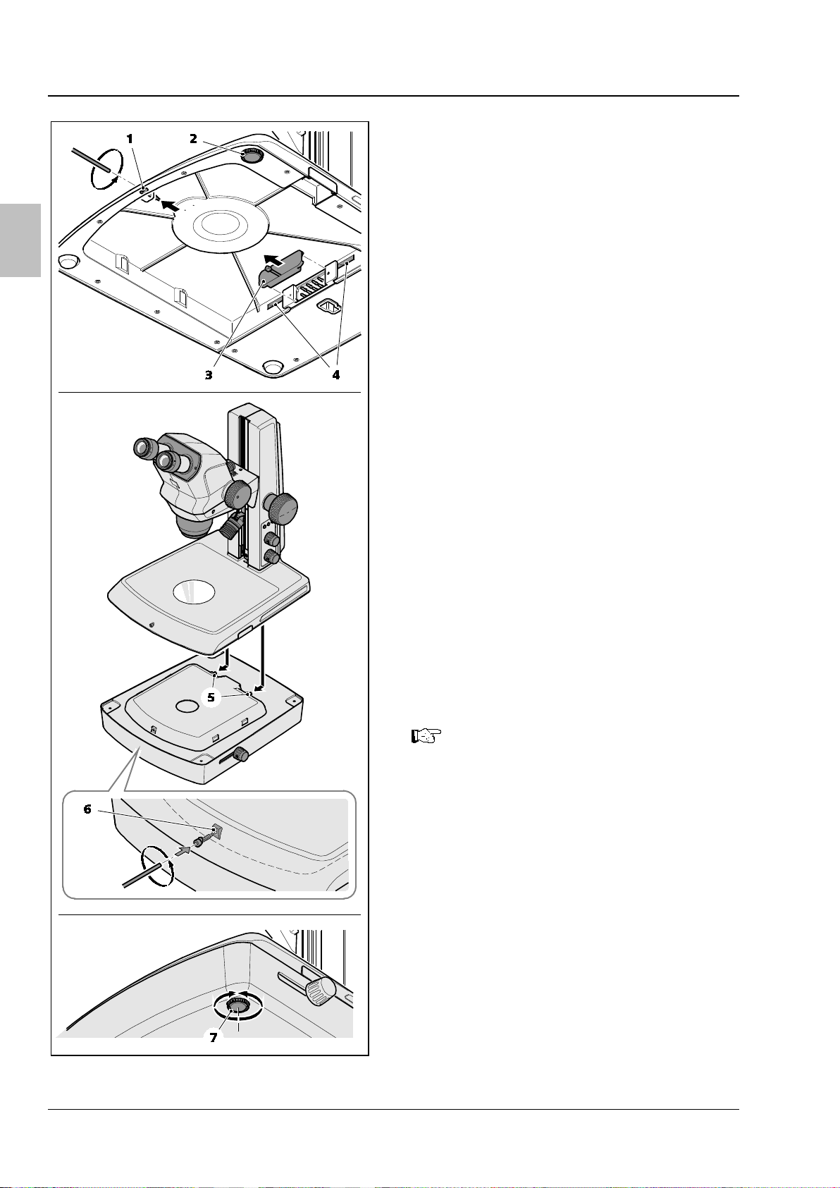
3.2 Mounting the Transillumination Unit M LED
• Unplug the power supply cable from the
stand.
• Place the Transillumination Unit on a stable
surface.
• Unscrew the 3 mm Allen screw (Fig. 3/1) on
the front of the stand and place it to one side.
• Screw the height-adjustable stand foot
(Fig. 3/2) in completely.
• Remove the cover flap (Fig. 3/3).
• Carefully mount the stand onto the
Transillumination Unit from the rear. Push it
forwards until the stand plate and transmitted
light housing are flush. The two lugs (Fig. 3/5)
must slot into the recesses (Fig. 3/4).
• Screw the 3 mm Allen screw into the tapped
hole (Fig. 3/6) of the Transillumination Unit
and tighten by hand.
• Return the stand to upright and, if necessary,
prevent wobbling by adjusting the heightadjustable foot of the Transillumination Unit
(Fig. 3/7).
• Plug the power supply cable back into the
stand.
To disassemble the Transillumination
Unit M LED, unscrew the Allen screw,
and remove it.
Fig. 3 Mounting the Transillumination Unit
4 435425-7144-008 06/2016

Stand M LED OPERATION ZEISS
Englis
turn the upper illumination
) to add a variable
light to the set
Detailed information on operating the
can be found in the
The rotating mirror has plain and
frosted mirror sides: use the plain side
contrast brightfield, and the
4 OPERATION
4.1 Operation of Stand M LED with Transilluminator Brightfield
• Press the lower knob (Fig. 4/2) to switch on
the transmitted light illuminator and adjust it
by turning the illumination intensity control.
• Toggle between brightfield (BF) and all-sided
darkfield (DF) illumination by moving the lever
(Fig. 4/3).
Press/
button (Fig. 4/1
amount of reflected
transmitted light.
optional reflected-light illuminators
K LED
Stemi 305 / 508 operating manual.
h
Fig. 4 Operating the Transilluminator
Brightfield
4.2 Operation of Stand M LED with Transillumination Unit
• Press the lower knob (Fig. 5/2) to switch on
the transmitted light illuminator and adjust it
by turning the illumination intensity control.
• To adjust the transmitted light brightfield
illumination, slide the rotary / slider button
(Fig. 5/3) to the rear position (BF).
• Then adjust the tilting angle of the rotating
mirror by turning the button until the
specimen is brightly illuminated from below.
for highdiffuse (frosted) mirror for homogenous
brightfield.
• To set lateral transmitted light darkfield
illumination, slide the control knob (Fig. 5/3)
to the front position (DF).
Fig. 5 Operating the Transillumination Unit
06/2016 435425-7144-008 5

ZEISS OPERATION Stand M LED
The switching status (on / off) and the brightness of all adapted illuminators are saved.
Exception: In the case of the K LED ring illumination, only the switching status (on / off) is
English
• Then adjust the tilting angle of the rotating mirror by turning the knob until the sample structures
appear brightly illuminated against a dark background.
Slide the rotary / slider button (Fig. 5/3) to a central position (RC) and then tilt the mirror to
create oblique illumination which reveals the structures of unstained specimens in relief
contrast.
Press/turn the upper illumination button (Fig. 5/1) to add a variable amount of reflected light
to the set transmitted light.
Detailed information on operating optional reflected-light illuminators K LED can be found in
the Stemi 305 / 508 operating manual.
4.3 Operation of the memory keys
Stand M LED has three memory buttons (Fig. 6/1)
to save different illumination settings and to
permit rapid switching between different
reflected, transmitted and mixed illumination
types.
To save an illumination setting, proceed as
follows:
• Turn on the desired illumination types
(reflected and / or transmitted light) by
pressing the top (Fig. 6/2) or bottom knob
(Fig. 6/3).
• Adjust the desired intensity of the reflected
and / or transmitted light illumination by
Fig. 6 Operating the memory keys
turning the top (Fig. 6/2) or bottom knob
(Fig. 6/3).
• Choose one of the three memory buttons
(Fig. 6/1) and hold it down for 3 seconds. All
3 buttons will light up when the settings have
been successfully saved.
• Repeat the process to assign the other two memory keys.
• To recall an illumination setting, press the relevant memory key shortly.
saved. The brightness and segment settings of the ring illumination are not saved and remain
unchanged when memory keys M1-M3 are pressed.
Factory reset: With Stand M LED switched off, press all three memory buttons M1-M3
simultaneously while switching on the stand. Memory slots M1 / 2 / 3 will be emptied and all
connected illuminators switched on at 50% brightness. Briefly pressing buttons M1-M3 now
causes no change in the illumination until a new setting is made.
6 435425-7144-008 06/2016

Stand M LED TECHNICAL DATA ZEISS
Englis
5 TECHNICAL DATA
Weight .................................................................................................................................... 4.6 kg
Optical risk group classification acc. to DIN EN 62471:2009
System ........................................................................................................... LED risk group 2 acc. to
.......................................................................................................................... DIN EN 62471:2009
Transillumination Unit M LED in Stand M LED ................................................. LED risk group 2 acc. to
.......................................................................................................................... DIN EN 62471:2009
Transilluminator Brightfield M LED in Stand M LED .......................................... LED risk group 2 acc. to
.......................................................................................................................... DIN EN 62471:2009
For detailed information on technical data refer to the operating manual for Stemi 305 / 508.
Dimensions of Stand M LED with Transilluminator Brightfield M LED
h
Dimensions of Stand M LED with Transillumination Unit M LED
06/2016 435425-7144-008 7


Stativ M LED EINLEITUNG ZEISS
unbedingt die Bedienungsanleitungen
508 sowie die Hinweise zur Gerätesicherheit und Installation für
rschiedenen Sprachen können Sie im
1 EINLEITUNG
Stativ M LED ist ein Zubehör zu den Stereomikroskopen Stemi 305 bzw. Stemi 508.
Zusätzlich zu der vorliegenden Anleitung sind daher
für Stemi 305 oder Stemi
Stemi 305/508 zu beachten. Dort enthaltene Sicherheitshinweise zu Stativ K EDU/LAB gelten
analog zu Stativ M LED.
Die aktuellen, detaillierten Gebrauchsanweisungen in ve
Downloadbereich der folgenden Webseiten herunterladen:
www.zeiss.de/Stemi305
www.zeiss.com/Stemi305
www.zeiss.de/Stemi508
Deutsch
www.zeiss.com/Stemi508
Stativ M LED ist das große Tischstativ zu den Stereomikroskopen Stemi 305 und Stemi 508. Dank seiner
großzügig bemessenen Arbeitsfläche und der 350 mm hohen Fokussiersäule eignet es sich sowohl für
ausgedehnte oder hohe Proben als auch zum parallelen Arbeiten mit mehreren Objekten.
Stativ M LED enthält Elektronik zur Ansteuerung der Auflicht- und Durchlichtbeleuchtungen K/M LED
(Zubehör).
Diese Gebrauchsanweisung beschreibt Installation und Bedienung des Stativs M LED sowie der
optionalen Durchlichtbeleuchtungen:
− Durchlichtmodul Hellfeld M LED und
− Durchlichteinheit M LED.
Detaillierte Informationen zu den Auflichtbeleuchtungen entnehmen Sie bitte den Bedienungsanleitungen für Stemi 305/508.
06/2016 435425-7144-008 1

ZEISS MIKROSKOPSYSTEM Stativ M LED
2 MIKROSKOPSYSTEM
Deutsch
1 Okular im Okularstutzen (z. B. Okular 10x/23)
2 Mikroskopkörper Stemi 508
3 Zoomknopf zum Einstellen der Vergrößerung, mit
zuschaltbaren Clickstops
4 Stativ M LED
5 Fokussiertrieb zum Scharfstellen des Objektes
6 Speichertasten Beleuchtungseinstellungen
7 Druck-/Drehknopf zum Ein- und Ausschalten sowie
Dimmen der Auflichtbeleuchtung
Bild 1 Stativ M LED mit Durchlichtmodul Hellfeld M LED (links) und Durchlichteinheit M LED
8 Druck-/Drehknopf zum Ein- und Ausschalten sowie
Dimmen der Durchlichtbeleuchtung
9 Auflichtbeleuchtung (z. B. Spot-Leuchte K LED)
10 Einlegeplatte zur Objektauflage
11 Hebel zur Umschaltung der Durchlichtbeleuchtung –
Hellfeld/Dunkelfeld am Durchlichtmodul Hellfeld
12 Dreh-/Schiebeknopf zur Einstellung der
Durchlichtbeleuchtung – Hellfeld, Schräglicht oder
Dunkelfeld – an der Durchlichteinheit M LED
2 435425-7144-008 06/2016

Stativ M LED MONTAGE DER DURCHLICHT-BELEUCHTUNGEN M LED ZEISS
3 MONTAGE DER DURCHLICHT-
BELEUCHTUNGEN M LED
VORSICHT
Vor Montage der Durchlichtbeleuchtung das Stativ ausschalten
und Netzkabel vom Stativ abziehen.
3.1 Montage des Durchlichtmoduls Hellfeld M LED
• Netzkabel vom Stativ abziehen.
• Stativ vorsichtig nach hinten kippen und
ablegen.
Deutsch
• Inbusschraube SW 3 (Bild 2/1) herausdrehen
und zur Seite legen.
• Abdeckkappen (Bild 2/2 und 3) entfernen.
• Durchlichtmodul so einsetzen, dass die beiden
Stifte (Bild 2/4) in die Aussparungen (Bild 2/5)
an der Stativunterseite eingreifen.
• Durchlichtmodul gegen die Stativplatte
drücken und festhalten.
• Inbusschraube SW 3 in die Gewindebohrung
(Bild 2/6) des Stativs einschrauben, bis die
Spitze der Schraube in die Bohrung des
Durchlichtmoduls greift.
• Die Inbusschraube handfest anziehen.
• Stativ wieder aufrecht hinstellen und ggf.
durch Einstellen des Stativfußes (Bild 2/7)
kippelfrei ausrichten.
• Netzkabel wieder am Stativ einstecken.
Bild 2 Durchlichtmodul Hellfeld M LED
montieren
06/2016 435425-7144-008 3
ZEISS MONTAGE DER DURCHLICHT-BELEUCHTUNGEN M LED Stativ M LED
3.2 Montage der Durchlichteinheit M LED
• Netzkabel vom Stativ abziehen.
Deutsch
• Durchlichteinheit auf einer stabilen Unterlage
platzieren.
• Inbusschraube SW 3 (Bild 3/1) an der
Vorderseite des Stativs herausdrehen und zur
Seite legen.
• Den höhenverstellbaren Stativfuß (Bild 3/2)
komplett einschrauben.
• Abdeckkappe (Bild 3/3) entfernen.
• Stativ vorsichtig von hinten auf die
Durchlichteinheit aufsetzen und nach vorn
schieben, bis Stativplatte und
Durchlichtgehäuse bündig ausgerichtet sind.
Die beiden Nasen (Bild 3/5) müssen in die
Aussparungen (Bild 3/4) eingreifen.
• Inbusschraube SW 3 in die Gewindebohrung
(Bild 3/6) der Durchlichteinheit einschrauben
und handfest anziehen.
• Stativ wieder aufrecht hinstellen und ggf.
durch Einstellen des höhenverstellbaren Fußes
in der Durchlichteinheit (Bild 3/7) kippelfrei
ausrichten.
Bild 3 Durchlichteinheit M LED montieren
• Netzkabel wieder am Stativ einstecken.
Für die Demontage der Durchlichteinheit die Inbusschraube lösen, das
Stativ vorsichtig nach hinten schieben
und abnehmen.
4 435425-7144-008 06/2016

Stativ M LED BEDIENUNG ZEISS
Durch Drücken/Drehen des oberen
) kann
dem eingestellten Durchlicht variabel
Der drehbare Spiegel verfügt über eine
klare und eine mattierte Spiegelseite:
reiches Hellfeld, Diffusspiegel für
4 BEDIENUNG
4.1 Stativ M LED mit Durchlichtmodul Hellfeld bedienen
• Durch Drücken des unteren Drehknopfes
(Bild 4/2) die Durchlichtbeleuchtung
einschalten und durch Drehen die
Beleuchtungsintensität einstellen.
• Durch Verstellen des Hebels (Bild 4/3)
zwischen Hellfeld- (BF) und allseitiger
Dunkelfeldbeleuchtung (DF) umschalten.
Beleuchtungsknopfes (Bild 4/1
Deutsch
Auflicht hinzugemischt werden.
Detaillierte Informationen zur Be-
dienung der Auflichtbeleuchtung entnehmen Sie der Bedienungsanleitung
Stemi 305/508.
4.2 Stativ M LED mit Durchlichteinheit bedienen
• Durch Drücken des unteren Drehknopfes
(Bild 5/2) die Durchlichtbeleuchtung
einschalten und durch Drehen die
Beleuchtungsintensität einstellen.
• Zur Einstellung einer Durchlicht-Hellfeld-
beleuchtung den Dreh-/Schiebeknopf
(Bild 5/3) in die hintere Stellung (BF) schieben.
Anschließend durch Drehen des Knopfes den
Kippwinkel des Drehspiegels verändern, bis
das Objekt von unten hell durchleuchtet wird.
Bild 4 Durchlichtmodul bedienen
Klarspiegel einschwenken für kontrast-
homogenes Hellfeld.
• Zur Einstellung einer seitlichen Durchlicht-
Dunkelfeldbeleuchtung den Bedienknopf
(Bild 5/3) in die vordere Stellung (DF) schieben.
06/2016 435425-7144-008 5
Bild 5 Durchlichteinheit bedienen

ZEISS BEDIENUNG Stativ M LED
in eine mittlere Position (RC) und
zusätzliches Kippen des Spiegels wird eine Schräglichtbeleuchtung erzeugt, die Strukturen
kann dem eingestellten
tzustand (An /
Aus) gespeichert. Helligkeit sowie Segmenteinstellungen der Ringleuchte werden nicht
drücken und das Stativ währenddessen einschalten. Die Speicher M1 / 2 / 3 werden geleert
% Helligkeit eingeschaltet.
M3 bewirkt nun bis zur erneuten Speicherung keine
• Anschließend durch Drehen des Knopfes den Kippwinkel des Drehspiegels verändern, bis die
Objektstrukturen hell vor dunklem Hintergrund leuchten.
Durch Verschieben des Dreh-/Schiebeknopfes (Bild 5
Deutsch
ungefärbter Objekte im Reliefkontrast sichtbar macht.
Durch Drücken/Drehen des oberen Beleuchtungsknopfes
Durchlicht variabel Auflicht hinzugemischt werden.
Detaillierte Informationen zur Bedienung der optionalen Auflichtbeleuchtungen K LED entnehmen Sie der Bedienungsanleitung Stemi 305/508.
4.3 Bedienung der Speichertasten
Das Stativ M LED besitzt drei Speichertasten
(Bild 6/1), um verschiedene Beleuchtungszustände zu hinterlegen und ein schnelles
Umschalten zwischen den verschiedenen
Auflicht, Durchlicht- und Mischlichtbeleuchtungen zu ermöglichen.
Um einen Beleuchtungszustand zu speichern, wie
folgt vorgehen:
/3)
(Bild 5/1)
• Die gewünschten Beleuchtungen (Auflicht
und / oder Durchlicht) durch Drücken des
oberen Drehknopfes (Bild 6/2) bzw. unteren
Drehknopfes (Bild 6/3) einschalten.
• Die Beleuchtungsintensität des Auflichts /
Bild 6 Speichertasten bedienen
Durchlichts durch Drehen des oberen
Drehknopfes (Bild 6/2) bzw. des unteren
Drehknopfes (Bild 6/3) einstellen.
• Die gewünschte Speichertaste (Bild 6/1) für 3 Sekunden gedrückt halten. Alle 3 Tasten leuchten auf,
wenn der Speichervorgang abgeschlossen ist.
• Bei der Belegung der anderen beiden Speichertasten analog verfahren.
• Um einen gespeicherten Beleuchtungszustand wieder aufzurufen, die gewünschte Speichertaste
kurz drücken.
Der Einschaltzustand (An / Aus) sowie die Helligkeit aller adaptierten Beleuchtungen werden
abgespeichert. Ausnahme: Bei der Ringleuchte K LED wird nur der Einschal
gespeichert und bleiben daher beim Aufrufen der Speichertasten M1-M3 unverändert.
Factory Reset: Bei ausgeschaltetem Stativ M LED alle drei Speichertasten M1-M3 gleichzeitig
und alle angeschlossenen Beleuchtungen werden mit 50
Kurzzeitiges Drücken der Tasten M1Beleuchtungsänderung.
6 435425-7144-008 06/2016

Stativ M LED TECHNISCHE DATEN ZEISS
5 TECHNISCHE DATEN
Masse ...................................................................................................................................... 4,6 kg
Optische Risikogruppeneinstufung nach DIN EN 62471:2009
Gesamtgerät ................................................................ LED-Risikogruppe 2 nach DIN EN 62471:2009
Durchlichteinheit M LED in Stativ M LED ........................ LED-Risikogruppe 2 nach DIN EN 62471:2009
Durchlichtmodul Hellfeld M LED in Stativ M LED ............ LED-Risikogruppe 2 nach DIN EN 62471:2009
Detaillierte Informationen zu den technischen Daten entnehmen Sie der Gebrauchsanweisung Stemi 305/508.
Abmessungen Stativ M LED mit Durchlichtmodul Hellfeld M LED
Deutsch
Abmessungen Stativ M LED mit Durchlichteinheit M LED
06/2016 435425-7144-008 7


Statif M LED INTRODUCTION ZEISS
Franç
consignes relatives à la sécurité de l'appareil et à l'installation de Stemi 305/508 doivent
impérativement être respectés. Les consignes de sécurité indiquées pour le statif K EDU/LAB
1 INTRODUCTION
Le statif M LED est un accessoire destiné aux stéréomicroscopes Stemi 305 et Stemi 508.
Outre le présent manuel, les modes d'emploi pour Stemi 305 ou Stemi 508 ainsi que les
sont également valables pour le statif M LED.
Vous pouvez télécharger les modes d’emplois actualisés et détaillés sur les sites suivants dans
la section de téléchargement de la langue correspondante :
www.zeiss.de/Stemi305
www.zeiss.com/Stemi305
www.zeiss.de/Stemi508
ais
www.zeiss.com/Stemi508
Le statif M LED est un grand statif de table pour les stéréomicroscopes Stemi 305 et Stemi 508. De par
sa surface de travail de grande dimension et sa colonne de mise au point d'une hauteur de 350 mm, ce
statif est parfaitement adapté pour les échantillons larges et élevés ainsi que pour le travail avec
plusieurs objets en parallèle.
Le statif M LED contient des éléments électroniques pour la commande de l'éclairage épiscopique ou
diascopique K/M LED (accessoires).
Ce mode d'emploi décrit l'installation et l'utilisation du statif M LED ainsi que des dispositifs d'éclairage
diascopique (à lumière transmise) disponibles en option :
− Module de lumière transmise à fond clair M LED et
− unité de lumière transmise M LED.
Des informations détaillées sur les dispositifs d'éclairage épiscopique (à lumière incidente) sont
indiquées dans les manuels relatifs à Stemi 305/508.
06/2016 435425-7144-008 1

ZEISS SYSTEME DE MICROSCOPE Statif M LED
1 Oculaire dans le support oculaire (par ex. oculaire
atténuer l'éclairage épiscopique
8 Bouton rotatif/poussoir pour activer, désactiver et
2 SYSTEME DE MICROSCOPE
Français
10x/23)
2 Corps de microscope Stemi 508
3 Bouton de zoom pour le réglage du grossissement,
avec arrêts enclenchables
4 Statif M LED
5 Commande de mise au point pour la focalisation de
l'objet
6 Touches d'enregistrement des paramètres d'éclairage
7 Bouton rotatif/poussoir pour activer, désactiver et
Figure 1 Statif M LED avec module de lumière transmise à fond clair M LED (à gauche) et l'unité de
lumière transmise M LED
atténuer l'éclairage diascopique
9 Éclairage épiscopique (par ex. spot K LED)
10 Plaque d'insertion pour support d'objet
11 Levier pour l'activation de l'éclairage diascopique à
fond clair/fond sombre sur le module de lumière
transmise fond clair
12 Bouton rotatif/coulissant pour le réglage de l'éclairage
diascopique – fond clair, lumière oblique ou fond
sombre – sur l'unité de lumière transmise M LED
2 435425-7144-008 06/2016

Statif M LED MONTAGE DES DISPOSITIFS D'ECLAIRAGE DIASCOPIQUE M LED ZEISS
Franç
Avant le montage de l'éclairage
diascopique, le statif doit être hors
tension et le câble d'alimentation
3 MONTAGE DES DISPOSITIFS
D'ECLAIRAGE DIASCOPIQUE
M LED
ATTENTION
retiré du statif.
3.1 Montage du module de lumière transmise à fond clair M LED
• Retirer le câble d'alimentation du statif.
ais
• Basculer avec précaution le statif vers l'arrière
et le poser.
• Dévisser la vis à six pans creux SW 3
(Figure 2/1) et la mettre de côté.
• Retirer les caches de protection (Figure 2/2
et 3).
• Poser le module de lumière transmise de sorte
que les deux pointes (Figure 2/4) entrent dans
les logements (Figure 2/5) de la partie
inférieure du statif.
• Pousser et maintenir le module de lumière
transmise contre la plaque du statif.
• Visser la vis à six pans creux SW 3 dans le trou
taraudé (Figure 2/6) du statif jusqu'à ce que la
pointe de la vis s'insère dans le trou du
module de lumière transmise.
• Serrer à la main la vis à six pans creux.
• Poser de nouveau le statif à la verticale et
régler éventuellement le pied du statif
(Figure 2/7) de sorte qu'il ne puisse pas
basculer.
• Insérer de nouveau le câble d'alimentation sur
le statif.
06/2016 435425-7144-008 3
Figure 2 Montage du module de lumière
transmise à fond clair M LED

ZEISS MONTAGE DES DISPOSITIFS D'ECLAIRAGE DIASCOPIQUE M LED Statif M LED
Pour le démontage de l'unité de
3.2 Montage de l'unité de lumière transmise M LED
• Retirer le câble d'alimentation du statif.
• Poser l'unité de lumière transmise sur un
support stable.
• Dévisser la vis à six pans creux SW 3
Français
(Figure 3/1) à l'avant du statif et la mettre de
côté.
• Visser complètement le pied du statif réglable
en hauteur (Figure 3/2).
• Retirer le cache (Figure 3/3).
• Placer avec précaution le statif par l'arrière sur
l'unité de lumière transmise et le pousser vers
l'avant jusqu'à ce que la plaque du statif et le
boîtier de lumière transmise soient alignés. Les
deux saillies (Figure 3/5) doivent s'imbriquer
dans les logements (Figure 3/4).
• Visser la vis à six pans creux SW 3 dans le trou
taraudé (Figure 3/6) de l'unité de lumière
transmise et la serrer à la main.
• Poser de nouveau le statif à la verticale et
ajuster éventuellement le pied à hauteur
réglable dans l'unité de lumière transmise
(Figure 3/7) de sorte qu'il ne puisse pas
basculer.
• Insérer de nouveau le câble d'alimentation sur
le statif.
lumière transmise, desserrer la vis à six
pans creux, pousser avec précaution le
statif vers l'arrière et le retirer.
Figure 3 Montage de l'unité de lumière
transmise M LED
4 435425-7144-008 06/2016

Statif M LED UTILISATION ZEISS
Franç
En appuyant sur / tournant le bouton
), une
lumière réfléchie variable peut être
Des informations détaillées sur
rage épiscopique
Le miroir tournant dispose d'un côté
et le miroir diffus pour un fond clair
4 UTILISATION
4.1 Utilisation du statif M LED avec le module de lumière transmise à fond clair
• En appuyant sur le bouton rotatif inférieur
(Figure 4/2), activer l'éclairage diascopique et
en le tournant, régler l'intensité de l'éclairage.
• Le réglage du levier (Figure 4/3) permet de
commuter entre l'éclairage à fond clair (BF) et
à fond sombre sur tous les côtés (DF).
d'éclairage supérieur (Figure 4/1
ajoutée à la lumière incidente réglée.
l'utilisation de l'éclai
sont disponibles dans le manuel relatif
à Stemi 305/508.
4.2 Utilisation du statif M LED avec l'unité de lumière transmise
• En appuyant sur le bouton rotatif inférieur
(Figure 5/2), activer l'éclairage diascopique et
en le tournant, régler l'intensité de l'éclairage.
ais
Figure 4 Utilisation du module de lumière
transmise
• Pour le réglage d'un éclairage diascopique à
fond clair, pousser le bouton rotatif/coulissant
(Figure 5/3) en position arrière (BF). Puis en
tournant le bouton, modifier l'angle
d'inclinaison du miroir tournant jusqu'à ce
que l'objet soit éclairé en clair par le bas.
clair et d'un côté dépoli : positionner le
miroir clair pour un fond clair contrasté
homogène.
• Pour le réglage d'un éclairage diascopique à
fond sombre latéral, pousser le bouton de
commande (Figure 5/3) en position avant (DF).
06/2016 435425-7144-008 5
Figure 5 Utilisation de l'unité de lumière
transmise

ZEISS UTILISATION Statif M LED
) est mis en position du milieu (RC) et que le
miroir est basculé plus loin, un éclairage oblique est créé. Les structures des objets non
L'état (marche/arrêt) ainsi que la luminosité de tous les éclairages adaptés sont enregistrés.
dans le cas de la lampe annulaire K LED, seul l'état (marche/arrêt) est enregistré.
La luminosité ainsi que les paramètres de segment de la lampe annulaire ne sont pas
enregistrés et restent par conséquent inchangés lors de l'activation des touches
doivent être actionnées simultanément et le statif mis en service en même temps. Les
M3, aucune modification
de l'éclairage n'est effectuée jusqu'au nouvel enregistrement.
• En tournant ensuite le bouton, l'angle d'inclinaison du miroir tournant peut être modifié jusqu'à ce
que les structures d'objet soient éclairées en clair devant un fond sombre.
Lorsque le bouton rotatif/coulissant (Figure 5
colorés apparaissent alors avec un contraste en relief.
En appuyant sur / tournant le bouton d'éclairage supérieur (Figure 5/1), une lumière réfléchie
variable peut être ajoutée à la lumière transmise réglée.
Français
Des informations détaillées sur l'utilisation des éclairages épiscopiques disponibles en option
se trouvent dans le manuel relatif à Stemi 305/508.
/3
4.3 Utilisation des touches d'enregistrement
Le statif M LED dispose de trois touches
d'enregistrement (Figure 6/1) afin de conserver
différents états d'éclairage et de pouvoir
commuter rapidement entre les divers éclairages
(épiscopique, diascopique et mixte).
Pour enregistrer un état d'éclairage, procéder
comme suit :
• activer les éclairages souhaités (épiscopique
et/ou diascopique) en appuyant sur le bouton
rotatif supérieur (Figure 6/2) ou sur le bouton
rotatif inférieur (Figure 6/3).
• Régler l'intensité d'éclairage de la lumière en
Figure 6 Utilisation des touches
d'enregistrement
appuyant sur le bouton rotatif supérieur
(Figure 6/2) ou sur le bouton rotatif inférieur
(Figure 6/3).
• Appuyer pendant 3 secondes sur la touche d'enregistrement souhaitée (Figure 6/1). Les 3 touches
s'éclairent lorsque l'enregistrement est terminé.
• Procéder de la même façon pour l'affectation des deux autres touches d'enregistrement.
• Pour appeler de nouveau un état d'éclairage enregistré, appuyer brièvement sur la touche
d'enregistrement souhaité.
Exception :
d'enregistrement M1-M3.
Réinitialisation : si le statif M LED est désactivé, les trois touches d'enregistrement M1-M3
mémoires M1 / 2 / 3 sont alors effacées et tous les éclairages raccordés sont activés avec une
luminosité de 50 %. En appuyant brièvement sur les touches M1-
6 435425-7144-008 06/2016

Statif M LED CARACTERISTIQUES TECHNIQUES ZEISS
Franç
Des informations détaillées sur les caractéristiques techniques sont disponibles dans les
5 CARACTERISTIQUES TECHNIQUES
Poids ........................................................................................................................................ 4,6 kg
Groupe de risque optique selon DIN EN 62471:2009
Ensemble du système ............................................. Groupe de risque LED 2 selon DIN EN 62471:2009
Unité de lumière transmise M LED .....................................................................................................
dans le statif M LED .............................................. Groupe de risque LED 2 selon DIN EN 62471:2009
Module de lumière transmise à fond clair M LED ................................................................................
dans le statif M LED .............................................. Groupe de risque LED 2 selon DIN EN 62471:2009
manuels relatifs à Stemi 305/508.
Dimensions du statif M LED avec le module de lumière transmise à fond clair M LED
ais
Dimensions du statif M LED avec l'unité de lumière transmise M LED
06/2016 435425-7144-008 7
 Loading...