

Page 1

Standard 25
ICS
Transmitted Light
Microscope
Operating Manual
Page 2

Standard 25
ICS
Knowledge of this manual is required for the operation of the instrument. Would you ther efore please
make yourself familiar with the contents of t his manual and pay special att ention to hint s concerning the
safe operation of the instrument.
The specifications are subject to change; the manual is not covered by an update service.
© Unless expressly authorized, forw arding and duplic ation of t his document , and the utiliz ation and
communication of its contents are not permitted. Violations will entail an obligation to pay
compensation.
All rights reserved in the event of granting of patents or registration of a utility model.
Issued by:
Carl Zeiss
Mikroskopie
D-07740 Jena
Telephone: (**49) 03641 / 64-1616
Telefax: (**49) 03641 / 64-3144
Internet: mikro@zeiss.de
http://www.zeiss.de
Number of this manual: B 40-029 e
Date of issue: 01/98
II B 40-029 e 01/98
Page 3

Standard 25
ICS
CONTENTS
Page
INTRODUCTION........................................................................................................................I
Title page...................................................................................................................................I
Copyright.................................................................................................................................. II
Contents...................................................................................................................................III
Notes on instrument safety.......................................................................................................IV
Warranty notes ........................................................................................................................VI
Overall view ............................................................................................................................VII
1 DESCRIPTION........................................................................................................................1-3
1.1 Name and intended application ..............................................................................................1-3
1.2 Instrument description and main features................................................................................1-3
1.3 Microscope configurations and modules .................................................................................1-4
1.4 Objectives ..............................................................................................................................1-6
1.5 Eyepieces ...............................................................................................................................1-7
1.6 Stage micrometers and eyepiece reticles .................................................................................1-8
1.7 Technical Data......................................................................................................................1-10
2 START-UP .............................................................................................................................2-3
2.1 Unpacking the instrument......................................................................................................2-3
2.2 Attachment of binocular tube 45°/20 ICS or binocular phototube 35°/20 ICS...........................2-3
2.3 Screwing-in of objectives........................................................................................................2-3
2. Insertion of eyepieces.............................................................................................................2-4
2.4.1 Insertion of eyepiece reticle.....................................................................................................2-4
2.4.2 Compensation of ametropia when eyepiece reticles are used ..................................................2-5
2.5 Setting of interpupillary distance and viewing height...............................................................2-5
2.6 Attachment of specimen holder to mechanical stage 75x30 R.................................................2-6
2.7 Attachment of condensers......................................................................................................2-7
2.7.1 Attach condenser 0.9 Z ..........................................................................................................2-7
2.7.2 Attach condenser II Z 0.9 Ph1, 2, 3 and D (0.6/0.9) .................................................................2-7
2.8 Connecting the instrument to the line.....................................................................................2-8
B 40-029 e 01/98 III
Page 4

Standard 25
ICS
3 OPERATION..........................................................................................................................3-3
3.1 Switch on the instrument.......................................................................................................3-3
3.2 Setting of transmitted-light brightfield for KÖHLER illumination...............................................3-4
3.3 Setting of transmitted-light phase contrast............................................................................. 3-6
3.4 Setting of transmitted-light darkfield......................................................................................3-8
3.5 Setting of transmitted light polarization contrast..................................................................... 3-9
3.6 Measurement of lengths...................................................................................................... 3-10
3.7 Attachment of photomicrography equipment....................................................................... 3-11
3.7.1 Attachment of SLR camera, e.g. CONTAX 167 MT................................................................ 3-11
3.7.2 Attachment of MC 80 DX microscope camera (35 mm film cassette)..................................... 3-13
3.8 Attachment of adapters for video cameras............................................................................3-14
3.9 Insertion of 8x drawing eyepiece.......................................................................................... 3-16
4 CARE, MAINTENANCE AND TROUBLESHOOTING............................................................... 4-3
4.1 Care and maintenance of the instrument................................................................................4-3
4.2 Troubleshooting..................................................................................................................... 4-4
4.2.1 Changing the fuses................................................................................................................4-4
4.2.2 Changing the 6 V 20 W halogen lamp.................................................................................... 4-5
4.2.3 Troubleshooting table ...........................................................................................................4-6
4.3 Table of spares, wearing parts and tools .............................................................................. 4-10
4.4 Requesting service................................................................................................................4-11
Annex...................................................................................................................................A-1
List of abbreviations ...............................................................................................................A-3
Physical and technical units.....................................................................................................A-4
Certification in accordance with DIN EN ISO 9001 / DIN EN 46001...........................................A-5
EC conformity declaration......................................................................................................A-7
IV B 40-029 e 01/98
Page 5

Standard 25
ICS
Notes on instrument safety
The Standard 25
microscope was designed, produced and tested in compliance with DIN 61010-1
ICS
(IEC 1010-1), Safety requirements for electrical measuring, control and laboratory instruments, and
meets the requirements of appendix I of directive 73/ 23/EC and the relevant CSA and UL directives. The
microscope meets the requirements of the EC direct ive 89/336/EC and the EMC legislation of November
9, 1992. This operation manual includes information and warnings which must be observed by the user.
The following warning and information symbols are used in this manual:
NOTE
This symbol (hand) is a warning which you must observe under all circumstances.
CAUTION
This symbol (warning triangle) is a warning which indicates a hazar d to the operation of the
instrument
.
CAUTION
Disconnect the instrument from the line!
B 40-029 e 01/98 V
Page 6

Standard 25
ICS
The Standard 25
microscope, including its original accessories, may only be used for the microscope
ICS
techniques described in this manual.
Particular attention must be paid to the following warning notes:
The Standard 25
microscope is categorized as Protection Class I and has been allocated the
ICS
protection degree IP 20. The power plug must be inserted in a properly installed socket
featuring a grounding contact. The grounding effect must not be made ineffective by an
extension cable which does not have a protective ground wire.
Before switching on the instrument, check whether it is suitable for the line voltage present.
Admissible voltage: 100...240 V AC, 50...60 Hz (depending on the model).
Always disconnect the instrument from the line before opening the instrument, before
changing the voltage and before changing the fuses.
When changing the instrument fuses, make sure to use only those of the rated power required
and the type indicated. The use of makeshift fuses and the short-circuiting of the fuse holders
are not permitted.
If it is established that the protection measures are no longer ef fective, t he instrument must be
switched off and safeguarded against inadvertent operation.
Dust and dirt can impair the performance of the instrument. Therefore, protect the instrument
against these influences as far as possible. If the microscope will not be used for longer
periods of time, it must be protected using the dust cover.
The instrument must be operated by trained personnel only who must be aware of the
possible danger involved with microscopy and the relevant application.
VI B 40-029 e 01/98
Page 7

Standard 25
ICS
The Standard 25
performance or damaged when handled improperly.
Notes on warranty:
The manufacturer guarantees that the instrument has no material and production defects
when delivered. You must inform us of any defects immediately and we must do anything to
minimize the damage. If the manufacturer is informed of such a defect, he is obliged to
remove it; it is his decision whether he does this by re pairing the instr ument or by deliver ing an
instrument free of any defect. No guarantee is provided for defects caused by natural wear
(wearing parts in particular).
microscope is an optical precision instrument which can be impair ed in its
ICS
The instrument manufacturer is not liable for damage caused by f aulty operation, negligence
or any other meddling with the instrument, or the use of accessories from other
manufacturers. This forfeits all the claims against warranty.
With the exception of the work specified in this manual, no maintenance or repair of the
Standard 25
may be performed. Repairs may only be performed by Zeiss service staff or
ICS
specially authorized personnel. Should any defect occur with the instrument, please get in
touch with your local Zeiss agency first.
B 40-029 e 01/98 VII
Page 8

Standard 25
ICS
Overall view of the Standard 25
microscope with polarization equipment
ICS
VIII B 40-029 e 01/98
Page 9

Standard 25
ICS
DESCRIPTION
Contents
1 DESCRIPTION.................................................................................................................1-3
1.1 Name and intended application........................................................................................1-3
1.2 Instrument description and main features.........................................................................1-3
1.3 Microscope configurations and modules...........................................................................1-4
1.4 Objectives........................................................................................................................1-6
1.5 Eyepieces.........................................................................................................................1-8
1.6 Stage micrometers and eyepiece reticles...........................................................................1-8
1.7 Technical Data...............................................................................................................1-10
List of illustrations
Fig. 1-1 Microscope modules........................................................................................................1-2
Fig. 1-2 Standard 25
microscope configurations.......................................................................1-4
ICS
B 40-029 e 01/98 1-1
Page 10
Standard 25
ICS
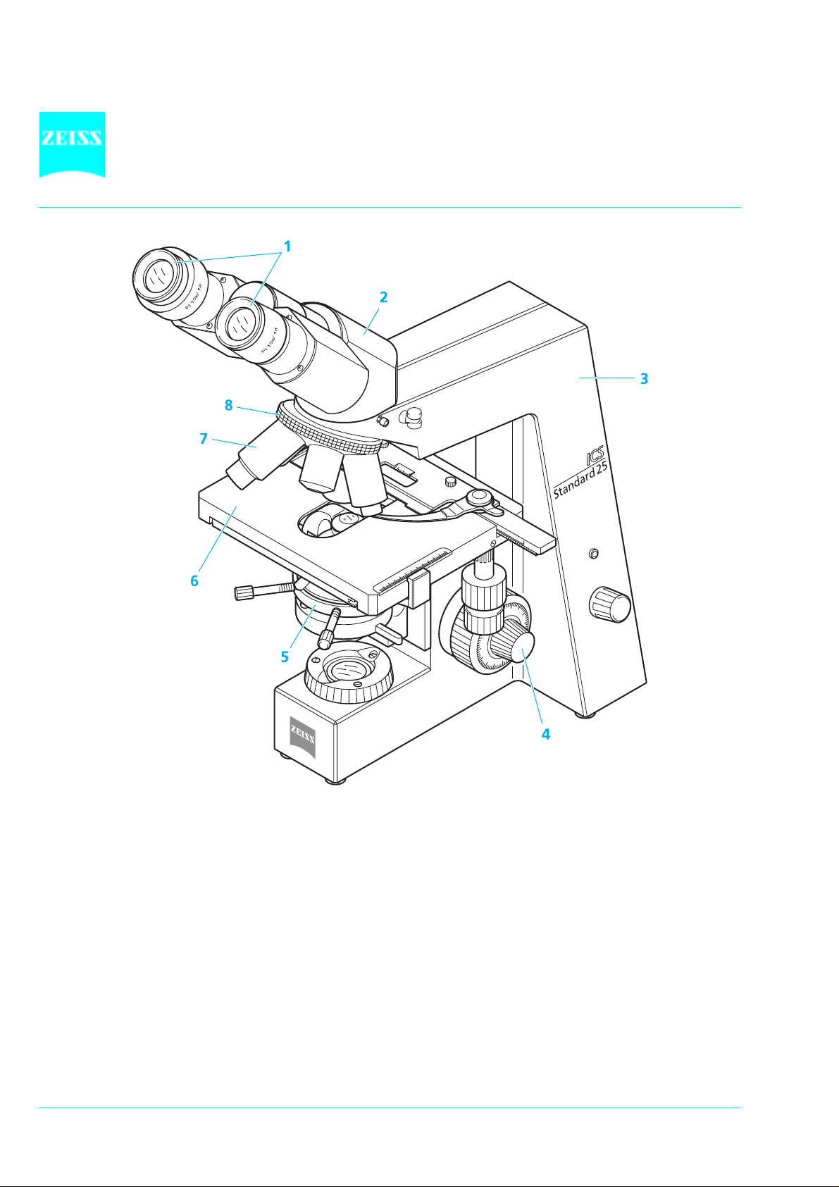
Fig. 1-1 Microscope modules
1 Eyepieces 5 Condenser carrier with condenser
2 Binocular tube 6 Mechanical stage with specimen holder
3 Stand 7 Objective
4 Coaxial coarse and fine drive 8 Objective nosepiece
1-2 B 40-029 e 01/98
Page 11

Standard 25
ICS
1 DESCRIPTION
1.1 Name and intended application
Manufacturer's name:Standard 25 ICS microscope
The Standard 25
forms in biology and medicine. These are typical application fields of the Standard 25
laboratory microscopy
doctor's offices
training (schools and universities).
microscope is a universal microscope for the visualization of fine structures and
ICS
:
ICS
1.2 Instrument description and main features
Thanks to its pyramid design, the Standard 25
is a compact transmitted-light microscope. In addition
ICS
to high-resolution ICS objectives and the major brightfield, darkfield, phase contrast and polarization
contrast techniques, an optional camera port for photo and video documentation is also available to the
user.
Major instrument features:
Sturdy and convenient stand in the pyramid design.
User-friendly coaxial coarse and fine drive
Mechanical stage 75x30 R with ceramic-coated stage surface and specimen holder
Space-saving and continuously adjustable, integrated illuminator with long-life 6V 20W halogen lamp.
Swing-in 0.9 Z condenser for brightfield, and Ph condenser II Z 0.9 for br ightfield and phase contrast
Ph1, 2 and 3.
Ball-bearing, 5-position nosepiece with W 0.8" thread.
ICS objectives in the price/performance categories CP-Achromat, A-Plan and Achroplan.
Binocular tube 45°/20 ICS with a viewing height of approx. 440 mm, and binocular photot ube 35°/ 20
with sliding prism 100 obs /100 doc.
10x eyepieces for the field numbers 20 or 18, suitable for spectacle wearers, fixed and adjustable.
B 40-029 e 01/98 1-3
Page 12
1.3 Microscope configurations and modules
Standard 25
ICS
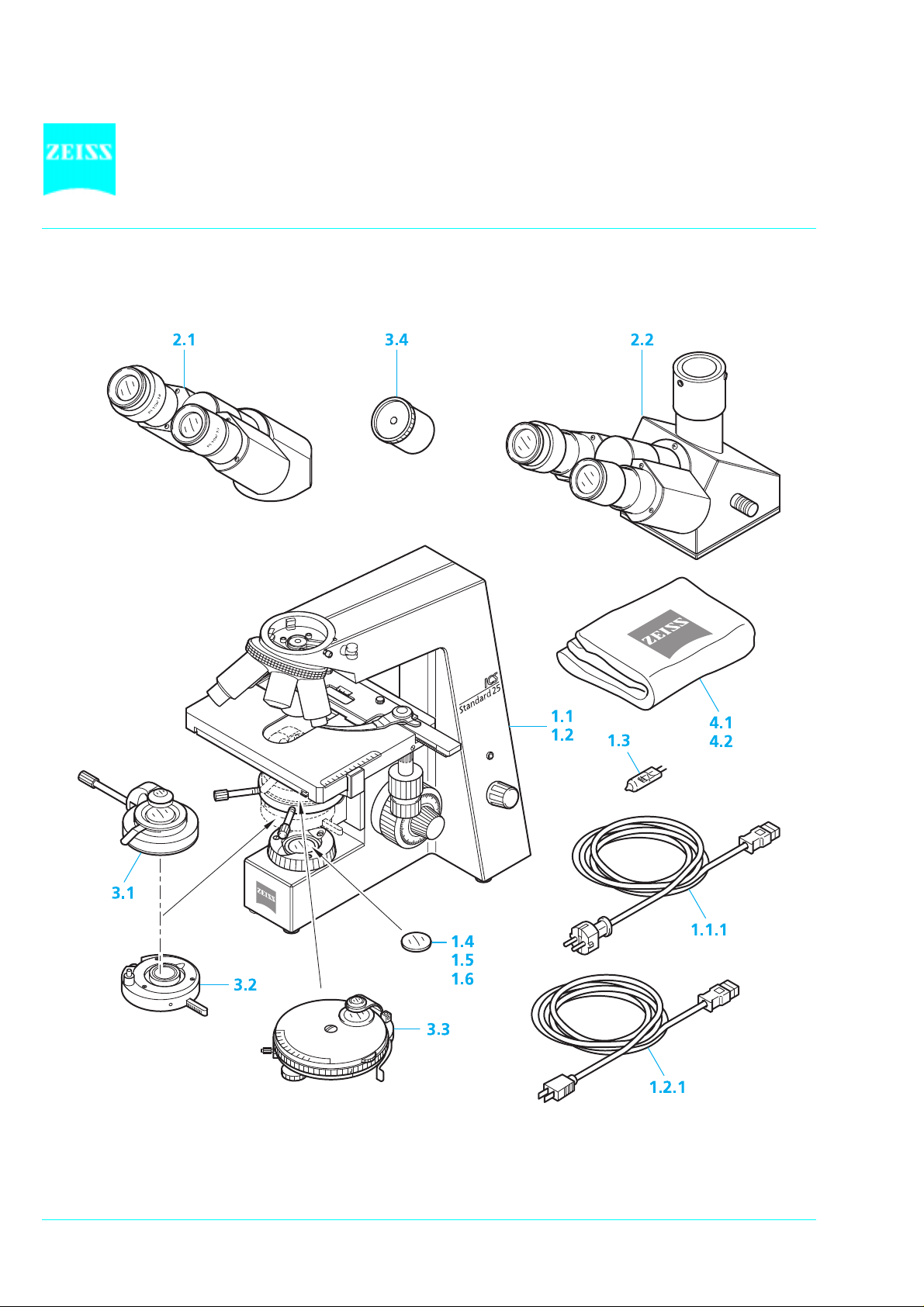
Fig. 1-2 Standard 25
microscope configurations with polarization equipment
ICS
1-4 B 40-029 e 01/98
Page 13

Standard 25
ICS
Cat. No.
Configurations
Standard 25
ICS
binocular microscope for transmitted-light brightfield and
phase contrast using CP Achromat objectives 10x, 40x Ph2 and 100x
"Standard 25
ICS
" binocular microscope for transmitted-light brightfield
using objectives "A-Plan" 10x, 40x and 100x
"Standard 25
ICS
" binocular microscope for transmitted-light brightfield and
phase contrast using objectives "A-Plan" 10x, 40x Ph 2 and 100x
"Standard 25
ICS
" binocular microscope for transmitted-light brightfield and
phase contrast using objectives "A-Plan" 10x, 20x Ph 2 and 40x Ph 2
"Standard 25
ICS
" binocular microscope for transmitted-light brightfield and
phase contrast using objectives "A-Plan" 10x Ph 1, 40x Ph 2 and 100x Ph 3
"Standard 25
ICS
" binocular microscope for transmitted-light brightfield using
objectives "A-Plan" 10x, 40x and 100x and phototube
"Standard 25
ICS
" binocular microscope for transmitted-light brightfield and phase contrast
using objectives "A-Plan" 10x, 40x Ph 2 and 100x and phototube
"Standard 25
ICS
" binocular microscope for transmitted-light brightfield and phase contrast
using objectives "A-Plan" 10x Ph 1, 40x Ph 2 and 100x Ph 3 and phototube
490841 9804
490841 9904
490845 9804
490845 9904
490846 9804
490846 9904
490847 9804
490847 9904
490848 9804
490848 9904
490865 9804
490865 9904
490866 9804
490866 9904
490868 9804
490868 9904
Modules
1.1 "Standard 25
ICS
" microscope stand with mechanical stage 75x30 R,
5-position nosepiece W 0.8, including integrated illuminator
stabilized power supply 220 ... 240 V/50 ... 60 Hz / 45 VA 450815 9902
1.1.1 Line cable with European plug
1.2 "Standard 25
ICS
" microscope stand with mechanical stage 75x30 R,
5-position nosepiece W 0,8, including integrated illuminator
stabilized power supply 100 ... 127 V / 50 ... 60 Hz / 45 VA 450816 9902
1.2.1 Line cable with American flat plug
1.3 Long-life 6 V 20 W halogen lamp (spare lamp) 380079 9690
1.4 Conversion filter CB 3; d=32x2 mm 467852
1.5 Conversion filter CB 12, d=32x2 mm 467850 9901
1.6 Interference wide-band filter, green, d=32x4 mm 467803
2.1 Binocular tube 45°/20
2.2 Binocular phototube 35°/20
ICS
ICS (
100% obs / 50% obs : 50% doc) 452929
452928
3.1 Swing-in 0.9 Z condenser 445211
3.2 Phase stop carrier Ph 2 for 445211 470864
3.3 Phase contrast condenser II Z 0.9 Ph 1, 2, 3 and D (0.6/0.9) 445210
not shown Dry darkfield condenser 0.7 - 0.85 and Z condenser holder 465506, 445215
not shown Dry darkfield condenser 0.8 - 0.95 and Z condenser holder 465505, 445215
not shown Ultra-condenser 1.2 - 1.4 and Z condenser holder 465500, 445215
3.4 Diopter d=30 mm 444020
4.1 Dust cover K 459300
4.2 Dust cover G (if binocular phototube is used) 459306
All the above microscope configurations with catalogue numbers ending in 9804 feature the line voltage 230 V,
and those ending in 9904 have a line voltage of 115 V.
B 40-029 e 01/98 1-5
Page 14

Standard 25
ICS
1.4 Objectives
The objectives are the optical centerpiece of the microscope. The following is an example of how
objectives can be labelled:
CP ACHROMAT 10x/0.25 /where
10x = objective magnification, with a defined color ring on the objective being allocated to each
magnification step (Zeiss color code)
0.25 = numerical aperture
= infinite tube length
- : can be used with cover slip thickness D = 0 or 0.17
or
0.17 = can be used with cover slip thickness D = 0.17
and
Oil = oil immersion objective
Ph 2 = phase contrast objective with a green color ring and phase stop Ph 2
The objective magnification multiplied by the eyepiece magnification (minimum 10x) results in the visual
overall magnification, e.g. 10 x 10 = 100x.
The numerical aperture x 1000, e.g. 0.25x1000 = 250x, is the highest useful magnification, i.e. no
further details are resolved above that limit.
The objective labeling indicates that these objectives may only be used with microscopes
featuring an infinite tube length and not with instrument s the objectives of which are marked
with "160" as their mechanical tube length.
The exact observance of the cover slip thickness of 0.17 mm is all the more necessary the higher the
numeric aperture of the objective. Therefore, so-called "Corr" objectives can be set for different cover
slip thicknesses via a correction ring. For this, a specimen area is searched, and the position of the
correction ring where optimum focus and image contrast are obtained is determined (refocusing is
always required).
Immersion objectives are always insensitive to differences in cover slip thickness.
When immersion objectives are used, the air between the cover slip and the objective is replaced with a
liquid, which is immersion oil in most cases. The plast ic oiler containing 20 ml of 581 N immersion oil is
particularly suitable for this purpose.
Due to their short working distance, objectives 25x and higher feature resilient mounts (specimen
protection). To prevent oil contamination of the specimen when the nosepiece is turned, the resilient
mounts of the immersion objectives can be locked in their lifted position by turning them to the r ight (do
not forget to unlock them again!).
1-6 B 40-029 e 01/98
Page 15

Standard 25
ICS
The following objectives are available for the Standard 25
Microscopy
Technique
Transm.-light brightfield CP-Achromat 5x/0.12 11.2 - 440920
Phase contrast CP-Achromat 10x/0.25 Ph 1 5.1 - 440931
Transm-light brightfield A-Plan 5x/0.12 9.9 - 441020
Phase contrast A-Plan 10x/0.25 Ph 1 4.4 - 441031
Transm.-light brightfield Achrostigmat 20x/0.45 1.6 0.17 440140
Objective Magnification/Num.
Aperture
CP-Achromat
CP-Achromat 10x/0.25 5.1 - 440930
CP-Achromat 40x/0.65 0.3 0.17 440950
CP-Achromat 100x/1.25 Oil 0.07 0.17 440980
CP-Achromat 40x/0.65 Ph 2 0.3 0.17 440951
CP-Achromat 100x/1.25 Oil Ph 2 0.07 0.17 000000 1007 159
CP-Achromat 100x/1.25 Oil Ph 3 0.07 0.17 440981
A-Plan
A-Plan 10x/0.25 4.4 - 441030
A-Plan 20x/0.45 0.53 0.17 441040
A-Plan 40x/0.65 0.43 0.17 441050
A-Plan 100x/1.25 Oil 0.22 0.17 441080
A-Plan 20x/0.45 Ph 2 0.53 0.17 441041
A-Plan 40x/0.65 Ph 2 0.43 0.17 441051
A-Plan 100x/1.25 Oil Ph 3 0.22 0.17 441081
Achrostigmat
Achrostigmat 40x/0.85 Oil 0.28 0.17 440250
Free working
distance in mm
microscope:
ICS
Cover slip
thickness D in
mm
Cat.No.
Phase contrast Achrostigmat 20x/0.45 Ph 2 1.6 0.17 440141
LD-Achrostigmat 20x/0.30 Ph 1 1.0...2.2 0...2.0 440147
LD-Achrostigmat 32x/0.40 Ph 1 1.5...2.2 0.5...1.5 440149
Achroplan
Transm.-light brightfield Achroplan 4x/0.10 11.1 - 440020
Achroplan 10x/0.25 4.8 - 440030
Achroplan 20x/0.45 2.07 0.17 440040
Achroplan 40x/0.65 0.59 0.17 440050
Achroplan 50x/0.90 Oil 0.29 0.17 440057
Achroplan 63x/0.80 0.29 0.17 440060
Achroplan 63x/0.95 0.15 0
(no cover slip)
Achroplan 100x/1.25 Oil 0.19 0.17 440080
Achroplan 100x/1.25 Oil Iris 0.19 0.17 440086
Phase contrast Achroplan 10x/0.25 Ph 1 4.8 - 440031
Achroplan 20x/0.45 Ph 2 2.07 0.17 440041
Achroplan 40x/0.65 Ph 2 0.59 0.17 440051
Achroplan 100x/1.25 Oil Ph 3 0.19 0.17 440081
Plan-Neofluar
Transm.-light brightfield Plan-Neofluar 2.5x/0.075 9.3 - 440310
440068
B 40-029 e 01/98 1-7
Page 16
1.5 Eyepieces
The following eyepieces are offered for the Standard 25 ICS:
Eyepiece Image Angle Cat. No.
Eyepiece PL 10x/18 Br. 39° 444131 9901
Eyepiece PL 10x/18 Br. foc. 39° 444132 9901
Eyepiece E-PL 10x/20 Br. 43° 444231 9901
Eyepiece E-PL 10x/20 Br. foc. 43° 444232 9902
Eyepiece PL 16x/16 Br. 54° 444053
Eyepiece PL 16x/16 Br. foc. 54° 444054
If required, eyecups for the eyepieces can be ordered under the Cat. No. 444801.
Standard 25
ICS
1.6 Stage micrometers and eyepiece reticles
Measuring and counting using the microscope requires stage micrometers and eyepiece reticles, a sm all
selection of which is listed below:
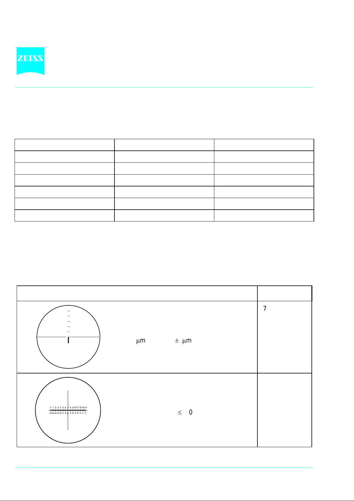
Illustration Description, Technical Data Cat. No.
Stage micrometer, positive 5 + 100/100 y D
474026
= 0.17 mm
gradation on the + y-axis: 5 mm in 5 intervals;
gradation on the - y-axis: 1 mm in 100/100 mm
= 10 m, accuracy 1m
Crossline micrometer disk 14:140 / d =26
454060
mm
gradation length=14 mm
increments = 0.1mm
gradation tolerance 0.001 mm
1-8 B 40-029 e 01/98
Page 17

Standard 25
ICS
Crossline disk / d = 26 mm 474064
Crossline micrometer disk 10:100 / d =26
mm
gradation length=10 mm
increments = 0.1mm
gradation tolerance 0.001 mm
Net micrometer 12.5x12.5/5;10 / d = 26 mm
area 12.5x12.5 mm, divided in fields of 5x5 or
10x10.
Photo reticle MC 2.5x / d = 26 mm
for 35 mm photography with an additional
magnification of 2.5x or for large-format
photography with a 10x additional
magnification.
474066 9901
474068
454075
If an eyepiece reticle is used, the binocular tube or the photot ube must be equipped with two
foc. eyepieces containing an adjustable eyelens, into one of which the eyepiece reticle is
mounted.
B 40-029 e 01/98 1-9
Page 18

Standard 25
ICS
1.7 Technical Data
(1) Dimensions (width x depth x height)
Stand with binocular tube..........................................................................approx. 200 x 350 x 450 mm
Stand with phototube ...............................................................................approx. 200 x 375 x 460 mm
Overall height including T2 adapter and CONTAX 167 MT camera housing..................... approx. 570 mm
(2) Weight
Standard 25
with binocular tube.................................................................................. approx. 6.7 kg
ICS
(3) Ambient conditions
Storage and transport (in packaging):
Permissible ambient temperature......................................................................................-40 to + 70° C
Permissible relative humidity (without condensation).............................................................max. 100 %
Operation:
Permissible ambient temperature..................................................................................... +10 to + 35° C
Permissible relative humidity (without condensation)...............................................................max. 85 %
Altitude.............................................................................................................................. max. 2000 m
Atmospheric pressure............................................................................................. 800 hPa to 1060 hPa
(4) Operating data
Operation........................................................................................................................... closed rooms
Protection class.......................................................................................................................................I
Enclosure protection........................................................................................................................IP 20
Electrical safety.................................................................in compliance with DIN EN 61010 (IEC 1010-1)
...............................................................................................................including CSA and UL directives
Pollution degree................................................................................................................................... 2
Overvoltage category.............................................................................................................................II
Radio interference suppression.......................................................in accordance with EN 55011, Class B
Line voltage...................................................................................................... 100 to 127 V AC (10%)
or 220 to 240 V AC (10%)
Line frequency...................................................................................................................... 50 to 60 Hz
Label of voltage range...............................................................................................see instrument rear
Power consumption...............................................................................................................max. 45 VA
Output voltage................................................................................stabilized, adjustable from 1.5 to 6 V
1-10 B 40-029 e 01/98
Page 19

Standard 25
ICS
(5) Fuses according IEC 127:
for 230 V........................................................................................................T 0.2 A; 250 V; 5 x 20 mm
for 115 V........................................................................................................T 0.4 A; 250 V; 5 x 20 mm
(6) Light source
Halogen lamp................................................................................................................... HAL 6 V 20 W
Adjustment of the light source...................................................................... continuous, 1.5 to 6 V DC
Color temperature at 6 V...........................................................................................................2800 K
Light flux..................................................................................................................................... 280 lm
Average life................................................................................................................................. 1000 h
Luminous area....................................................................................................................2.0 x 2.0 mm
(7) Opto-mechanical data
Stand with stage focusing........................................................................... with coarse drive (4mm/rot)
.....................................................................................................................and fine drive (0.4mm /rot)
...................................................................................................................................Overall lift 15 mm
Objective change.............................................................................................manually via 5x nosepiece
Objectives.................................................................................ICS line of objectives with W 0.8" thread
Eyepieces ........................................................................................................... 30 mm plug-in diameter
with field number 18.......................................................... Pl 10x/18 Br. and Pl 10x/18 Br. foc. or
with field number 20........................................................ E-Pl 10x/20 Br. and E-Pl 10x/20 Br. foc.
Specimen stage .............................................................. mechanical stage 75x30 R with ceramic surface
Dimensions (width x depth) ...................................................................................160 x 140 mm
Travel range (width x depth)......................................................................................75 x 30 mm
Specimen holder ...............................................with spring clip to the right or for one-handed operation
Swing-in condenser 0.9 Z..........................................for M
.................................................................................. for M
< 10x swing out condenser front lens 0.9
Obj.
10x swing in condenser front lens 0.9
Obj.
Binocular tube 45°/20 ICS
maximum field number............................................................................................................20
interpupillary distance............................................................ can be set between 55 and 75 mm
Viewing angle ........................................................................................................................45°
Viewing height ..................................................................................................approx. 440 mm
Visual port..............................................................................................................tube factor 1x
1
2
1
For photography using artificial light color reversal film for 3200 K, the conversion filter CB 3 (467852)
produces the correct color temperature in the light path.
2
The scale on the coarse drive (0 to 400) permits the orienting measurement of the object thickness:
1 increment corresponds to approx. 5 µm
B 40-029 e 01/98 1-11
Page 20

Binocular phototube 35°/20
maximum field number........................................................................................................... 20
interpupillary distance ........................................................... can be set between 55 and 75 mm
viewing angle.........................................................................................................................35°
viewing height ..................................................................................................approx. 430 mm
visual port..............................................................................................................tube factor 1x
camera/video port..................................................................................................tube factor 1x
camera/video port..............................................................................................interface 60 mm
switched via sliding prism...........................................................100% obs / 50% obs : 50% doc
Standard 25
ICS
1-12 B 40-029 e 01/98
Page 21

Standard 25
ICS
START-UP
Contents
2 START-UP.......................................................................................................................2-3
2.1 Unpacking the instrument................................................................................................2-3
2.2 Attachment of binocular tube 45°/20 ICS or binocular phototube 35°/20 ICS....................2-3
2.3 Screwing-in of objectives .................................................................................................2-3
2.4 Insertion of eyepieces ......................................................................................................2-4
2.4.1 Insertion of eyepiece reticle..............................................................................................2-4
2.4.2 Compensation of ametropia when eyepiece reticles are used ...........................................2-5
2.5 Setting of interpupillary distance and viewing height ........................................................2-5
2.6 Attachment of specimen holder to mechanical stage 75x30 R...........................................2-6
2.7 Attachment of condensers...............................................................................................2-7
2.7.1 Attach condenser 0.9 Z....................................................................................................2-7
2.7.2 Attach condenser II Z 0.9 Ph1, 2, 3 and D (0.6/0.9)...........................................................2-7
2.8 Connecting the instrument to the line..............................................................................2-8
List of illustrations
Fig. 2-1 Attachment of binocular tubes.........................................................................................2-3
Fig. 2-2 Screwing-in of objectives .................................................................................................2-3
Fig. 2-3 Attachment of eyepieces .................................................................................................2-4
Fig. 2-4 Insertion of eyepiece reticle..............................................................................................2-4
Fig. 2-5 Setting the interpupillary distance and viewing height of the binocular tube .....................2-5
Fig. 2-6 Attachment of specimen holder to mechanical stage 75x30 R...........................................2-6
Fig. 2-7 Attachment of condenser 0.9 Z........................................................................................2-7
Fig. 2-8 Attachment of phase contrast condenser II Z 0.9 Ph 1, 2, 3 and D (0.6/0.9) ......................2-7
Fig. 2-9 Connecting the instrument to the line..............................................................................2-8
B 40-029 e 01/98 2-1
Page 22

Standard 25
ICS
2-2 B 40-029 e 01/98
Page 23

Standard 25
ICS
2 START-UP
The Standard 25
microscope, including
ICS
accessories, is delivered in standard packaging. We
would recommend you to keep the packaging
material so that the instrument can be stored for a
longer period of time or returned to the
manufacturer.
2.1 Unpacking the instrument
Remove the microscope from the transport case
and place it on the worktable.
or
ICS
ICS
.
2.2 Attach binocular tube 45°/20
binocular phototube 35°/20
Loosen hexagonal screw (2-1/5) using the SW3
ball-headed screwdriver (2-1/4). Remove dust
covers (2-1/1) from tube underside and the
dovetail mount on the stand.
Hold the binocular tube (2-1/3) or the binocular
phototube 2-1/2) in a slightly inclined position
and attach it to the stand mount via the
dovetail. Turn the binocular tube into the
required observation position and tighten the
hexagonal screw using the screwdriver.
Fig. 2-1 Attachment of binocular tubes
2.3 Screwing-in of objectives
Remove dust caps (2-2/2) according to the
number of objectives and screw objectives (22/3) in nosepiece (2-2/1) clockwise one by one,
starting with the lowest magnification.
The dust caps should remain on
those nosepiece eyes which are not
required.
Fig. 2-2 Screwing-in of objectives
B 40-029 e 01/98 2-3
Page 24

Fig. 2-3 Insertion of eyepieces
Standard 25
2.4 Insertion of eyepieces
Remove both protection caps (2-3/1) from the
binocular tube (2-3/2).
Insert the fixed eyepiece, e.g. Pl 10x/18 Br. (23/3) in the right tube and the focusing eyepiece
Pl 10x/18 Br. foc. (2-3/4) in the left tube.
The focusing eyepiece is used to
compensate for ametropia of the
eyes.
ICS
Fig. 2-4 Insertion of eyepiece reticle
If eyepiece reticles are inserted into the unscrewed mount by the customer, attent ion must be
paid to the labelling being visible the right way up after insertion.
2.4.1 Insertion of eyepiece reticle
The eyepieces Pl 10x/18 Br. foc. and E-Pl 10x/20
Br. foc. are intended for use with eyepiece reticles
(see overview under 1.6).
The slight image shift caused by the additional
path through the glass is taken into account on
the diopter scale by the fact that the zero point
position is indicated not by the white dot W (24/W) but by the red dot R (2-4/R).
The eyepiece reticles (2-4/1) have been adhered to
screw-in mounts (2-4/2) to allow easy
replacement.
To replace a reticle, unscrew the screw-on
mount or the part containing the eyepiece
reticle and replace it with the required one.
2-4 B 40-029 e 01/98
Page 25

Standard 25
ICS
2.4.2 Compensation of ametropia when eyepiece reticles are used
The correct use of an eyepiece reticle requires two focusing eyepieces, e.g. Pl 10x/18 Br. foc., to enable
compensation of ametropia.
Use the eyelens of the focusing eyepiece to focus on the line figure of the eyepiece reticle; focus on
the edge of the field of view if no eyepiece reticle is used.
Focus on the microscope image of a specimen via the focusing drive by looking through the eyepiece
with reticle.
When the image and the eypiece reticle are in focus in the above eyepiece, focus the image for the
second eye via the focusing eyelens of the second eyepiece.
The position of the focusing drive on the stand must not be changed.
2.5 Setting of interpupillary distance
and viewing height
The eyepiece distance is matched to the
individual interpupillary distance by s winging the
eyepiece tubes symmetrically towards one
another.
The viewing height can be increased (2-5/A) or
reduced (2-5/B) by turning the entire binocular
tube through 180°.
Fig. 2-5 Setting the interpupillary distance
and viewing height of the binocular
tube
B 40-029 e 01/98 2-5
Page 26

Standard 25
ICS
2.6 Attachment of specimen holder to
mechanical stage 75x30 R
Fig.2-6 Attachment of specimen holder to
mechanical stage 75x30 R
The Standard 25
features the mechanical stage
ICS
75x30 R with ceramic coating (2-6/6).
The specimen is precisely moved in x and y using
the user-friendly coaxial drive (2-6/4).
The x/y gradation on the stage surface (2-6/5) with
the two vernier scales helps to relocate certain
specimen spots.
The readily mounted specimen holder with spring
clip R (453536) (2-6/1) is part of the standard
configuration.
As an alternative, it is also possible to use
- the specimen holder with sprig clip R (473448)
(2-6/2)
or
- the specimen holder for one-handed operation
(453548) (2-6/3).
Here, the microscope slide (2-6/7) is inserted
into the specimen holder along the guiding
edge, the spring clip is swung out and will
automatically clamp the microscope slide in its
stop position.
The specimen holders can be easily exchanged
in the x-direction using the two fixation screws
on the guiding rail. Loosen the two fixation
screws, pull out specimen holder to the front
and insert new specimen holder until it engages
in the guiding slots. Tighten the two fixation
screws again.
2-6 B 40-029 e 01/98
Page 27

Standard 25
ICS
2.7 Attachment of condensers
2.7.1 Attach condenser 0.9 Z
Unscrew both centering screws (2-7/3) on the
condenser carrier (2-7/2) until the condenser 0. 9
Z (2-7/9) can be easily inserted in the condenser
carrier.
Insert condenser 0.9 Z (2-7/9) in the condenser
carrier (2-7/2) in such a way that, firstly, the
dovetail of the condenser is pressed against
spring pin (2-7/1) in the condenser carrier and,
secondly, the aperture diaphragm lever (2-7/8)
can be conveniently operated from the front.
Tighten both centering screws (2-7/3) on the
condenser carrier (2-7/2) until they engage in
the dovetail and keep the condenser (2-7/9) in
position.
The Ph 2 phase stop carrier (2-7/4) must be
mounted as follows:
Screw locking screw (2-7/6) into the left drilled
hole (2-7/7) on the underside of the condenser
carrier. The locking screw keeps the Ph 2 phase
stop carrier in its functional position.
Then screw Ph 2 phase stop carrier (2-7/ 4) into
the drilled hole (2-7/5) on the underside of the
condenser carrier.
2.7.2 Attach phase contrast condenser II
Z 0,9 Ph 1, 2, 3 and D (0.6/0.9)
With the exception of the orientation in the
condenser carrier (2-7/2), the phase contrast
condenser II Z 0.9 is inserted in the Standard 25
ICS
in the same way as the above condenser 0.9 Z.
Insert condenser II Z 0.9 (2-8/1) in the condenser
carrier (2-7/2) in such a way that knob (2-8/2)
points to the observer.
Fig. 2-7 Attachment of condenser 0.9 Z
Fig. 2-8 Attachment of phase contrast
condenser II Z 0.9 Ph 1, 2, 3 and D
(0.6/0.9)
B 40-029 e 01/98 2-7
Page 28

Standard 25
2.8 Connecting the instrument to the line
Check whether the voltage indicated at the rear of the instrument complies with the line
voltage!
Do not connect the instrument to the line if the inst r ume nt voltage and the line voltage are not
identical and make sure to inform the nearest CZ agency or CZ service agency.
Connect the line cable with connector (2-9/4) to the instrument socket (2-9/3) and connect the earthcontact plug (2-9/5) to the line.
Switch on the instrument via the on/off switch (2-9/2) on the instrument rear.
The green LED (2-9/1) lights up to indicate that the instrument is ready for operation (on/off switch in
"I" position), and the integrated halogen lamp must also be on.
ICS
Fig. 2-9 Connecting the instrument to the line
2-8 B 40-029 e 01/98
Page 29

Standard 25
ICS
OPERATION
Contents
3 OPERATION ...................................................................................................................3-3
3.1 Switch on the instrument.................................................................................................3-3
3.2 Setting of transmitted-light brightfield for KÖHLER illumination........................................3-4
3.3 Setting of transmitted-light phase contrast.......................................................................3-6
3.4 Setting of transmitted-light darkfield................................................................................3-8
3.5 Setting of transmitted light polarization contrast ..............................................................3-9
3.6 Measurement of lengths................................................................................................3-10
3.7 Attachment of photomicrography equipment.................................................................3-11
3.7.1 Attachment of SLR camera, e.g. CONTAX 167 MT .........................................................3-11
3.7.2 Attachment of MC 80 DX microscope camera (35 mm film cassette)..............................3-13
3.8 Attachment of adapters for video cameras.....................................................................3-14
3.9 Insertion of 8x drawing eyepiece....................................................................................3-16
List of illustrations
Fig. 3-1 Switch on the instrument.................................................................................................3-3
Fig. 3-2 Insertion of filters.............................................................................................................3-3
Fig 3-3 Setting of brightfield........................................................................................................3-4
Fig 3-4 Setting of interpupillary distance of binocular tube ...........................................................3-4
Fig 3-5 Setting of diaphragm images according to KÖHLER..........................................................3-5
Fig 3-6 Setting of phase contrast using condenser 0.9 Z ..............................................................3-6
Fig 3-7 Centering of phase stops in phase contrast ......................................................................3-7
Fig 3-8 Setting of phase contrast using Ph condenser II Z 0.9........................................................3-7
Fig 3-9 Setting of polarization contrast ........................................................................................3-9
Fig 3-10 Measurement of lengths................................................................................................3-10
Fig 3-11 Attachment of SLR camera, e.g. CONTAX 167 MT.........................................................3-11
Fig 3-12 Attachment of MC 80 DX microscope camera................................................................3-13
Fig 3-13 Insertion of 8x drawing eyepiece ...................................................................................3-16
B 40-029 e 01/98 3-1
Page 30

Standard 25
ICS
3-2 B 40-029 e 01/98
Page 31

Standard 25
ICS
3 OPERATION
3.1 Switch on the instrument
Switch on the instrument via the on/off switch
(3-1/3) on the instrument rear. The green LED
(3-1/2) must light up.
Set the required brightness via the "Brightness"
control (3-1/1).
Depending on the application, place one or several
of the following dia. 32 filters (3-2/ 1) on the dustprotection glass of the luminous-field diaphragm:
interference wide-band filter, green, 32x4, for
contrast enhancement in b/w photography of
stained sections and for phase contrast;
CB 3 conversion filter, 32x2, to generate the
correct color temperature of 3200 K when
artificial light color reversal film is used.
CB 3, 32x2, and CB 12, 32x2, conversion filters
for use with daylight color film
The Standard 25
is supplied with factory-aligned illumination. The illumination need not be
ICS
adjusted even when the lamp is exchanged by the customers themselves.
Fig. 3-1 Switch on the instrument
Fig. 3-2 Insertion of filters
B 40-029 e 01/98 3-3
Page 32

3.2 Setting of transmitted-light brightfield for KÖHLER illumination
As described in chapter 2, the microscope is ready
for operation and switched on according to
section 3.1.
If the Ph 2 phase stop carrier (3-3/4) is available
on condenser 0.9 Z (3-3/6), it should be sw ung
out of the optical beam path for microscopy in
transmitted-light brightfield.
Furthermore, the following basic settings of the
microscope are required:
First, place a high-contrast specimen w ith 0.17
mm cover slip on the mechanical stage 75x30 R
(3-3/8).
Swing 10x objective into beam path via knurled
ring (3-3/9) of the nosepiece.
Look throught the fixed eyepiece of the
binocular tube (3-3/1) first and focus on the
Fig. 3-3 Setting of brightfield
object via the focusing drive (3-3/2).
Then set the focus for the other eye by turning
the eyelens of the focusing eyepiece.
The eyepiece distance is matched to the
individual interpupillary distance by swinging
the eyepiece tubes symmetrically towards one
another.
Set the interpupillary distance in such a way
that you can see a sharply limited field of view
with both eyes.
The viewing height can be increased (3-4/A) or
reduced (3-4/B) by turning the entire binocular
tube through 180°.
Standard 25
ICS
Fig. 3-4 Setting of interpupillary distance of
the binocular tube
3-4 B 40-029 e 01/98
Page 33

Standard 25
ICS
The KÖHLER illumination principle requires the following set tings of the condenser, the luminous-field
diaphragm and the aperture diaphragm:
Move condenser 0.9 Z (3-3/6) to the upper stop position via the condenser drive, swing condenser
front lens 0.9 into the optical beam path and move aperture diaphragm in the center position via
lever (3-3/5).
Set (reduce) diameter of the luminous-field diaphragm (3-3/3) unt il it is visible in the field of view ( 35/A). Focus the edge of the luminous-field diaphragm by slightly lowering the condenser (color-free
edge) (3-5/B) and center the image of the luminous-field diaphragm using the two condenser
centering screws (3-3/7) (3-5/C).
Open the luminous-field diaphragm (3-3/3) until it just disappears behind the edge of t he field of view
(3-5/D).
Fig. 3-5 Setting of diaphragm images according to KÖHLER
Depending on which specimen is used, the image contrast can be adjusted via the aperture
diaphragm (3-3/5). For specimens featuring normal contrast, the aperture diaphragm (3-3/5) should
be set to approx. 2/3 of the diameter of the exit pupil of the objective.
This can be easily checked and set when the eyepiece is removed (3-5/E).
Finally, refocus the specimen via the coaxial fine drive (3-3/2).
Since field size and objective aperture change after every objective change, the setting of the
luminous-field diaphragm and the aperture diaphragm must be repeated as described above.
For all objective magnifications V
10x, the condenser front lens 0.9 must be swung out of
obj
the beam path.
B 40-029 e 01/98 3-5
Page 34

Standard 25
ICS
3.3 Setting of transmitted-light phase contrast
The phase contrast technique is mainly used to increase the image contrast of unstained specimens.
As described in chapter 2, the microscope is ready for operation and swit ched on according to section
3.1.
The microscope must be set for transmitted-light brightfield, as described in section 3.2.
The further steps depend on whether phase contrast equipment A or B is used.
Optimum phase contrast requires a high level of cleanliness! Therefore, clean the front lens of
the objective used, the visible condenser surfaces, the upper cover slip surface and the lower
carrier plate surface of the specimen with particular care and carefully remove grease.
Equipment A
condenser 0.9 Z (3-6/9) and Ph 2 phase stop
carrier (3-6/7)
phase contrast objectives labelled "Ph 2"
(3-6/11), suitable also for transmitted-light
brightfield
Settings:
Place unstained specimen on the mechanical
stage:
Screw phase-contrast objective, e.g. 40x/ 0.65 Ph
2 (3-6/11), into nosepiece and swing it into t he
beam path.
Remove condenser front lens 0.9 from the beam
path via lever (3-6/10).
Open the luminous-field diaphragm (3-6/5) and
the condenser aperture diaphragm (3-6/8).
Swing in phase stop carrier (3-6/7) with Ph 2
phase stop.
Set the required brightness.
Check whether phase stop centering complies
with figure (3-7/B). For this, remove one
eyepiece and replace it with the diopter or a
centering telescope (3-6/3).
If required, center the phase stop via the two
centering screws (3-6/6) using the SW 1.5
Fig. 3-6 Setting of phase contrast using
condenser 0.9 Z
screwdriver. The diopter or the centering
telescope (3-6/3) must then be replaced with the
eyepiece again.
3-6 B 40-029 e 01/98
Page 35

Standard 25
ICS
Complete phase contrast is available only if the dark
phase ring in the objective covers the bright phase
stop in the condenser completely and precisely (also
see Fig. 3-7/B).
To achieve this, the diopter or the centering
telescope (3-6/3) must be inserted in tube (3-6/4)
instead of an eyepiece. Focus on the phase ring by
turning the eyelens (3-6/1) of the centering
telescope via the knurled ring (3-6/2).
Equipment B
phase contrast condenser II Z 0.9 Ph1, 2, 3
(3-8/1)
phase contrast objectives labelled "Ph 2"
(3-6/11), suitable also for transmitted-light
brightfield
Fig. 3-7 Centering of phase stops in phase
contrast
Settings:
Insert phase contrast condenser II Z 0.9 Ph 1, 2,
3 (3-8/1) in the condenser carrier as described in
section 2.
Screw phase contrast objective (3-6/11) into the
nosepiece and swing it into the optical beam
path.
Set the object in brightfield first by having the
turret disk (3-8/5) click-stop in position "J".
Swing in the condenser front lens (3-8/2) via
6
lever (3-8/4).
Reduce luminous-field diaphragm (3-6/5), focus
it using the condenser, center it and open it
again (as described in section 3.2, page3-5).
Optimum image contrast in brightfield is
Fig. 3-8 Setting of phase contrast using Ph
condenser II Z 0.9
obtained by setting the aperture diaphragm via setting wheel (3- 8/3). The aperture diaphragm can be
centered using knurled wheel (3-8/6) and fixed using lever (3-8/7) which can be clamped in position.
Swing phase stop Ph 1, 2 or 3 assigned to the phase contrast objective in t he beam path via turret
disk (3-8/5).
Check centering of both phase stops using the centering telescope (3-6/3) in the tube, as described
above.
If the phase rings are out of center, as shown in Fig. ( 3-7/A), use knurled wheel (3-8/6) to make the
bright phase stops in the condenser exactly congruent with the dark phase ring in the object ive, as
shown in Fig. (3-7/B).
B 40-029 e 01/98 3-7
Page 36

Standard 25
ICS
3.4 Setting of transmitted-light darkfield
Darkfield is mainly used for small or m inute objects such as treponema, spir ochaeta, cilia and bacteria,
but also for emulsions or unstained objects in watery solutions.
The special benefit of the darkfield technique is its natural, true rendition of the original colors (color
fidelity).
The equipment required for darkfield always includes a condenser with central stop, the numerical
aperture of which exceeds that of the objective used. For further details please see the following table.
Condenser with illumination aperture suitable objective apertures
Ph condenser II Z 0.9 in position Ph 3 0.44
Ph condenser II Z 0.9 in position D 0.6/0.9)
dry darkfield condenser 0.7 - 0.85
0.4
0.4 -0.55
0.4 - 0.6
on condenser holder Z
dry darkfield condenser 0.8 - 0.95
0.6 - 0.75
on condenser holder Z
Ultracondenser 1.2 - 1.4
0.75 - 1.0
on condenser holder Z
Higher objective magnifications or apertures require objectives with an integrated iris aperture.
As described in chapter 2, the microscope is ready for operation and swit ched on according to section
3.1.
The microscope must be set for transmitted-light brightfield, as described in section 3.2.
Settings:
Correct condenser height until image background appears in optimum darkness.
Checking the objective pupil reveals whether it is dark indeed; for this purpose, remove the eyepiece
from the tube and view the objective exit pupil.
Setting of darkfield is made easier by performing precentration using an objective of a lower pow er.
Since the luminous field is visible only where particles light up, while the final specimen, however,
might be "empty" over large areas, we would recommend you to use a specimen for initial setting
which features a homogeneous distribution of details, e.g. a blood smear.
Darkfield microscopy requires specimens and optical surfaces to be extremely clean. Finger
prints and traces of grease in particular have negative effects, since they brighten the
background of the field of view.
3-8 B 40-029 e 01/98
Page 37

Standard 25
ICS
3.5 Setting of transmitted-light polarization contrast
As described in chapter 2, the microscope is ready for operation and swit ched on according to section
3.1.
Transmitted-light polarization contrast requires the
following equipment:
- polarizer, oriented in EAST-WEST direction,
(453615) (3-9/3), mounted on swing-out
carrier.
- analyzer (3-9/1), oriented in NORTH-SOUTH
direction, and lambda plate (3-9/2) are
mounted on two separate sliders (453692) and
integrated into the stand head. To enable the
function to be performed, the sliders must be
pushed in.
Settings:
First, set a suitable object in brightfield as
described in section 3.2.
Swing the polarizer (3-9/3) in the beam path.
If only the analyzer slider (3-9/1) is pushed in,
black-and-white polarization contrast is
produced; the additional insertion of the
lambda plate (3-9/2) makes the objects appear
in colored polarization contrast.
The sliders containing the analyzer and the lambda plate must always be pushed in until stop
to make them fully effective and to avoid the field if view to be cut off.
Retrofitting of the polarization equipment can be perform ed by the Zeiss service agency (see
section 4.4).
Fig. 3-9 Setting of polarization contrast
B 40-029 e 01/98 3-9
Page 38

Standard 25
ICS
3.6 Measurement of lengths
The measurement of lengths using the Standard 25 ICS requires the following, for example:
stage micrometer, positive 5 + 100/100 y D = 0.17 mm
and
eyepiece crossline micrometer 10:100, d = 26 mm
An overview of available stage micrometers and eyepiece reticles is given in chapter 1.6.
Before the length measurement using the microscope can be perfor med, the micrometer or scale value
of the used objective / eyepiece reticle combination must be determined. This scale value is exactly that
distance in the specimen which complies to one interval of the used eyepiece crossline micrometer.
For calibration, align the scales of the stage micrometer and the crossline micrometer parallel to each
other by turning the eyepiece, and make the zero lines of both scales exactly congruent. If, for example,
99 increments (of 20 µm each) of the stage micrometer correspond to exactly 100 increments of the
crossline micrometer, as in Fig. 3-10, the resulting scale value k’ for the used objective / eyepiece reticle
combination (A-Plan 10x/0.25 and crossline micrometer 10:100) is
99
k' =
x 10 m = 9.9 m
100
The distance to be measured should be 5 mm in the intermediate eyepiece image in order to
keep the influence of random measuring deviations as low as possible.
Other measuring errors may occur if the eyepiece has not been inserted into the tube until
stop.
After exchange of the stage micrometer for the
specimen to be measured, the measuring distance
of interest results from the number of increments
of the eyepiece crossline micrometer (tenth
estimated) multiplied by the scale value k’.
Example:
L = 35.5 x 9.9 mm = 351.5 µm
Particularly large object structures can also be
determined by using the vernier scale gradations
(0.1 mm) on the mechanical stage. Here, it might
be necessary to determine the distance to be
measured through calculation from a combined x
and y measurement (Pythagoras).
Fig. 3-10 Measurement of lengths
3-10 B 40-029 e 01/98
Page 39

Standard 25
ICS
3.7 Attachment of photomicrography equipment
The Standard 25
microscope with camera tube can be changed from observation to photography via
ICS
a pushrod (3-11/7 or 3-12/8) (pushrod pulled out for photomicrography). Special adapters allow
commercially available 35 mm SLR cameras and special microscope cameras (e.g. MC 80
attached to the camera port of the Standard 25
. For the use of the photomicrography equipment,
ICS
) to be
DX
please observe the relevant separate manuals in addition to the information provided in this manual.
3.7.1 Attachment of SLR camera, e.g. CONTAX 167 MT
Screw T-2 adapter for the CONTAX bayonet (311/3) on the 2.5x connector for T2 (3-11/4)
(456005).
Attach the camera housing (3-11/ 2) and fix the
cable release (3-11/1), if required.
Loosen the three hexagonal screws (3-11/6),
remove the dust cover (3-11/8) from the
camera tube (3-11/5) and insert the
premounted unit A in the camera tube.
Align the camera unit in the required position
and tighten the three hexagonal screws (3-8/6).
Pull out pushrod (3-11/7) completely for
photomicrography.
When artificial light color reversal film is used,
the CB 3 conversion filter provides the correct
color temperature of 3200 K. The filt er must be
placed on the dust protection glass of the
luminous-field diaphragm (3-2/5), as mentioned
in section 3.1.
For daylight color reversal film, the CB 12
conversion filter must be used in addition to the
CB 3 conversion filter.
If focusing is not to be made via the
viewfinder of the camera, the
component with the eyepiece reticle
must be screwed in the eyepieces (also
see section 1.6).
Fig. 3-11 Attachment of SLR camera, e.g.
CONTAX 167 MT
B 40-029 e 01/98 3-11
Page 40

Various T2 adapters for SLR cameras are listed below:
T2 adapters to SLR cameras Cat. No.
T2 adapter for CONTAX (CONTAX bayonet) 416010
T2 adapter for OLYMPUS OM (OM bayonet) 416002
T2 adapter for MINOLTA (SR bayonet) 416003
T2 adapter for CANON (FD bayonet) 416004
T2 adapter for NIKON (F bayonet) 416009
T2 adapter for PENTAX (KA bayonet) 416011
For detailed information on SLR cameras please see ma nual G 42-406/II entitled "35 mm SLR
cameras for microscopes and stereomicroscopes".
Standard 25
ICS
3-12 B 40-029 e 01/98
Page 41

Standard 25
ICS
3.7.2 Attachment of MC 80 DX microscope camera (35 mm film cassette)
Insert adapter 60 for microscope camera (312/5) (456006) in camera tube (3-12/6) and fix
it using three hexagonal screws (3-12/7).
Insert projection lens P 2.5x (3-12/4) in adapter
60 for microscope camera (3-12/5).
Attach MC 80
basic body (3-12/2) on
DX
adapter 60 for microscope cameras until stop
and fix it by clamping ring (3-12/3)
anticlockwise.
Attach 35 mm film cassette Mot DX (3-12/1) to
the basic body in such a way that the contact
pins firmly engage in the relevant sockets.
Pull out pushrod (3-12/8) completely for
photomicrography.
When artificial light color reversal film is used,
the CB 3 conversion filter provides the correct
color temperature of 3200 K. The filter must be
placed on the dust protection glass of the
luminous-field diaphragm (3-2/5), as
mentioned in section 3.1.
For daylight color reversal film, the CB 12
conversion filter must also be used. The filter
must be placed on the dust cover of the
luminous-field diaphragm (3-2/5), as described
in section 3.1.
For detailed information on the
MC 80
, please see manual B 40-
DX
036-e.
Fig. 3-12 Attachment of MC 80
camera
microscope
DX
B 40-029 e 01/98 3-13
Page 42

Standard 25
ICS
3.8 Attachment of adapters for video cameras
The following video adapters and video zoom adapters with 60 mm interface permit the attachment of
one-chip b/w and color CCD cameras and three-chip color CCD cameras to the camera tube of the
Standard 25
ICS
.
Tube Adapter
Cameras
456105
60
C 2/3“
1.0x
456119
60
C 1/3“ (3CCD)
0.5x
456115
60
ENG 2/3“
1.0x
456107
60
C 2/3“
0.63x
456108
60
C 1/3“
0.4x
456117
60
ENG 2/3“
0.8x
456106
60
C 1/2“
0.5x
456123
Zoom 60
C 2/3“
0.4x ... 2x
456121
Zoom 60
ENG 2/3“
0.4x ... 2x
456124
Zoom 60
ENG 1/2“
0.5x ... 2.4x
456122
Zoom 60
ENG 1/2“
0.4x ... 2x
456118
60
ENG 1/2“
0.63x
3-14 B 40-029 e 01/98
Page 43

Standard 25
ICS
The connecting piece 60 - 44 also allows video adapters with 44 mm interface to be used with the
camera tube of the Standard 25 ICS with 60 mm interface.
Video adapters
(Cat.No.)
456140
Connecting piece 60 - 44
Microscopes with 60 mm interface and all
video adapters for 44 mm interface.
Suitable for:: Comments
Connects video adapters for 44mm interface
to microscopes with 60 mm interface.
Attachment of video cameras:
Loosen three hexagonal screws and remove dust cover from the camera tube of the Standard 25
Screw video adapter or video zoom adapter with C-mount thread into the video camera.
Insert video adapter or video zoom adapter in ENG 2/2" or ENG ½“ bayonet of the video camera and
clamp it tight.
Insert premounted unit (video camera with video adapt er or video zoom adapter) in camera tube of
the Standard 25
, align it and fix it using the three hexagonal screws.
ICS
ICS.
Insert eyepiece with photo reticle in the binocular tube and align photo reticle parallel to the camera.
Pull out pushrod on the binocular phototube to direct 50% of the light to the camera port.
Set the required zoom magnification factor via the wheel of the video zoom adapter.
If required, adjust image brightness on the monitor by changing the lamp brightness on the
microscope stand.
The instructions of the camera manufacturer must also be observed when operating the video
camera.
B 40-029 e 01/98 3-15
Page 44

3.9 Insertion of 8x drawing eyepiece
Standard 25
ICS
The 8x drawing eyepiece (444126) is an accessory for microscopic drawing and can only be used in
combination with the binocular phototube 35°/20
1
CS on the Standard 25
The eyepiece contains a
ICS.
beam splitter which allows the simultaneous observation of the microscope image and the drawing area.
As described in chapter 2, the microscope is ready
for operation and switched on according to
section 3.1.
The microscope must be set for transmitted-light
brightfield, as described in section 3.2.
Settings:
Remove one eyepiece (3-13/1) and insert the 8x
drawing eyepiece (3-13/3) in the binocular
phototube 35°/20
(3-13/2) instead of it.
ICS
Swing 8x drawing eyepiece until the drawing
area (DIN A4 notepad) lying in front of the
stand appears symmetrically aligned also in the
field of view.
Screw on the drawing eyepiece.
Illuminate the drawing area in such a way that
Fig. 3-13 Insertion of 8x drawing eyepiece
it can be seen in the same quality as the
microscope image. If required, reduce the
brightness of the microscope image via the
brightness control (3-1/1).
A special drawing pencil is supplied to facilitate
drawing.
1
35°/20 means a viewing angle of 35° and the maximum field number 20.
3-16 B 40-029 e 01/98
Page 45

Standard 25
ICS
CARE, MAINTENANCE AND TROUBLESHOOTING
Contents
4 CARE, MAINTENANCE AND TROUBLESHOOTING........................................................4-3
4.1 Care and maintenance of the instrument .........................................................................4-3
4.2 Troubleshooting ..............................................................................................................4-4
4.2.1 Changing the fuses..........................................................................................................4-4
4.2.2 Changing the 6 V 20 W halogen lamp.............................................................................4-5
4.2.3 Troubleshooting table .....................................................................................................4-6
4.3 Table of spares, wearing parts and tools ........................................................................4-10
4.4 Requesting service.........................................................................................................4-11
List of illustrations
Fig. 4-1 Changing the fuses..........................................................................................................4-4
Fig. 4-2 Changing the 6 V 20 W halogen lamp .............................................................................4-5
B 40-029 e 01/98 4-1
Page 46

Standard 25
ICS
4-2 B 40-029 e 01/98
Page 47

Standard 25
ICS
4 CARE, MAINTENANCE AND TROUBLESHOOTING
4.1 Care and maintenance of the instrument
Maintenance of the Standard 25
Cover the instrument with the dust cover after every use.
Do not set up the instrument in a damp room, i.e. max. humidity 85%.
Remove dust from optical surfaces using a rubber blower or a natural hair brush. Use alcohol to
is limited to the following operations:
ICS
remove grease from brush, then dry the brush. Remove stubborn dirt and fingerprints using a dustfree cloth or leather cloth.
Remove stubborn dirt (e.g. fingerprints) from optical surfaces using commercially available optics
cleaning cloths; if necessary, slightly moisten the cloths with petroleum ether.
Clean the front lenses of the objectives using petroleum ether, but do not use alcohol.
When using the Standard 25
Store the Standard 25
in humid climatic zones, proceed as follows:
ICS
in bright, dry and well ventilated rooms with a humidity of less than 85%;
ICS
store particularly sensitive components and accessories, such as objectives and eyepieces, in a dry
closet.
When the equipment is stored in closed cases for a longer period of time, t he growth of fungus can
be avoided by including cloths soaked in fungicide in the cases.
The risk of growth of fungus on opto-mechanical instruments always exists in the following conditions:
relative humidity of more than 75% and temperatur es between +15° C and +35° C for more than
three days.
installation in dark rooms without air ventilation, and
dust deposits and fingerprints on optical surfaces.
B 40-029 e 01/98 4-3
Page 48

4.2 Troubleshooting
Troubleshooting is described in further detail using the following two examples:
changing the fuses, and
changing the 6 V / 20 W halogen lamp.
Further measures are summarized under 4.2.3.
4.2.1 Changing the fuses
Standard 25
ICS
Fig. 4-1 Changing the fuses
Switch off the instrument via the on/off switch (4-1/1) and disconnect earth-contact plug (4-1/4) from
the line; if required, also disconnet flat plug (4-1/3) from the instrument connector (4-1/2).
Check line cable and instrument plugs (4-1/3 and 4) and exchange them, if required.
Press marked lock (4-1/5) in the direction of the arrow and remove fuse holder (4-1/6). Check fuse
inserts (4-1/7) for compliance with the line voltage and check whether resistance wires are OK.
for 230 V: T 0.2 A; 250 V
for 115 V: T 0.4 A; 250 V
Be absolutely sure that you replace defective fuse inserts. For the catalogue numbers of spare fuses
please see page 4-10 in section 4.3.
4-4 B 40-029 e 01/98
Page 49

Standard 25
ICS
4.2.2 Changing the 6 V 20 W halogen lamp
The following procedure is required to exchange the lamp:
Switch off lamp supply via on/off switch (4-1/2)
and allow lamp to cool down for approx. 15
minutes.
Disconnect the earth-contact plug (4-1/4) from
the line and remove the flat plug (4-1/3) from
the instrument connector (4-1/2).
Disconnect the instrument from the line and
place it on the back to make the underside of
the pyramid stand accessible.
Fold down cover (4-2/2) and pull out defective
halogen lamp (4-2/1).
Use the protective film or a clean paper cloth to
hold the new 6 V 20 W halogen lamp and
insert both lamp pins carefully into the
receptacles.
Do not touch the lamp bulb with your
bare hands; if required, clean t he bulb
with clean alcohol before switching it
on for the first time in order to avoid
dirt to burn in.
The Standard 25
is supplied with factory-aligned illuminat ion. The illumination need not be
ICS
Fig. 4-2 Changing the 6 V 20 W halogen lamp
adjusted even when the lamp is exchanged by the customers themselves.
Fold up cover again, turn the stand upside again and connect the stand to the line.
B 40-029 e 01/98 4-5
Page 50

4.2.3 Troubleshooting table
Problem Cause Remedy
Standard 25
ICS
vignetting or unhomogeneous
image brightness in the field of
view
the field of view is not entirely
visible
The pushrod on the camera tube is
not in the correct position
(observation/photography)
Nosepiece with objective not
switched to stop position
Move the pushrod in the correct
position (end position), see pages
3-11 and 3-13.
Switch nosepiece with objective
in stop position
Condenser not set correctly. Set condenser correctly
(adjustment, centering), see
pages 3-4, 3-5
Aperture diaphragm not set
correctly.
Set aperture diaphragm correctly
(centering, opening), see page
3-5.
Luminous-field diaphragm not set
correctly.
Set luminous-field diaphragm
correctly (centering, opening), see
page 3-5.
Filter not inserted correctly in filter
mount.
Insert filter correctly in filter
mount, see page 3-3.
4-6 B 40-029 e 01/98
Page 51

Standard 25
ICS
Problem Cause Remedy
Low resolving power and poor
image contrast
Aperture diaphragm opening not
set correctly.
Set aperture diaphragm opening
in accordance with the 2/3 rule or
depending on the specimen
features, see page 3-5.
Condenser not focused correctly
and condenser lens 0.9 not
switched correctly.
Wrong cover slip thickness for
0.17 transmitted light objectives
Use of no or unspecified
immersion oil with CZ immersion
Focus condenser and set
condenser lens 0.9 correctly or
switch it off, see pages 3-4, 3-5.
Use the correct 0.17 mm cover
slips
Use CZ immersion oil 518 N, see
page 4-10.
objectives
Air bubbles in the immersion oil Apply oil again to remove the
bubbles.
Immersion oil at the front lens of a
dry objective
Corr. Ring is not set to the correct
cover slip thickness
Clean the front lens of the dry
objective, see page 4-3.
Set the corr. ring to the correct
thickness, see page 1-6.
Dirt or dust on the optical surfaces
of objectives, eyepieces,
Clean the appropriate
components, see page 4-3
condensers or filters
Image aberration Condenser not set correctly. Set condenser correctly, see pages
3-4, 3-5
Nosepiece not correctly switched
Correctly click-stop nosepiece
to stop position
Great focus differences after
objective change
Specimen is not fixed on the
mechanical stage
Focusing eyepieces are not set
correctly.
Correctly set specimen in
specimen holder and fix it.
Set focusing eyepieces to the
appropriate ametropia, s. page 2-5
B 40-029 e 01/98 4-7
Page 52

Problem Cause Remedy
Standard 25
ICS
Left and right fields of view
cannot be combined into an
Interpupillary distance of the
binocular tube is not set correctly.
image
Focusing eyepieces are not set
correctly.
Eye-fatiguing microscopy Interpupillary distance of the
binocular tube is not set correctly.
Focusing eyepieces are not set
correctly.
Image brightness not acceptable Reduce lamp voltage or insert
Dirt or dust in the field of view Condenser not focused correctly
and condenser lens 0.9 not
switched correctly.
Aperture diaphragm opening too
small
Dirt or dust on the optical surfaces
of objectives, eyepieces,
condensers, filters or specimens
Set interpupillary distance
correctly, see pages 2-5, 3-4
Set focusing eyepieces to the
appropriate ametropia, s. page 2-5
Set correct interpupillary distance,
see pages 2-5 and 3-4.
Set focusing eyepieces to the
appropriate ametropia, s. page 2-5
conversion filter
Focus condenser and set
condenser lens 0.9 correctly or
switch it off, see pages 3-4, 3-5.
Set aperture diaphragm opening
in accordance with the 2/3 rule or
depending on the specimen
features, see page 3-5.
Clean the optical surfaces of the
appropriate components, see page
4-3
The 6 V 20 W halogen lamp
does not function although the
on/off switch is in "on"
Line cable not connected to the
line.
Connect line cable to the line and
make sure to check the instrument
and line voltage, see page 2-6.
position
6 V 20 W halogen lamp not
installed
Install 6 V 20 W halogen lamp, see
page 4-5
6 V 20 W halogen lamp defective Exchange 6 V 20 W halogen lamp,
see page 4-5
The specified 6 V 20 W halogen
lamp is not used.
Use the specified 6 V 20 W
halogen lamp, see page 4-10.
Defective fuses Exchange fuses, see page 4-4.
Electronics module possibly
defective
Have electronics module checked
by service and replaced, if required
(see page 4-11)
4-8 B 40-029 e 01/98
Page 53

Standard 25
ICS
Problem Cause Remedy
The 6 V 20 W halogen lamp
flickers, unstable brightness
End of average life of 6 V 20 W
halogen lamp
Incorrectly installed or broken line
cable
The pins of the 6 V 20 W halogen
lamp are not correctly inserted
into the receptacle
Replace 6 V 20 W halogen lamp,
see page 4-5
Correctly connect line cable or
replace it, see page 4-4
Corectly insert pins of 6 V 20 W
halogen lamp in receptacle, see
page 4-5
B 40-029 e 01/98 4-9
Page 54

4.3 Table of spares, consumables and tools
Description Cat. No. Application
Standard 25
ICS
6 V 20 W long-life halogen lamp 380079 9690.000 for the integrated Standard 25
ICS
illumination
SW 3 ball-headed screwdriver 000000 0069.551 to change the tubes
Eyepiece eyecup 444801 0000.00 recommended for techniques with
a low brightness level in order to
suppress light reflection
Dust cover for nosepiece
Dust cover for eyepiece tube
Immersion oil 518 N ;
20 ml oiler
100 ml bottle
250 ml bottle
500 ml bottle
462981 0000.000
000000 0168.373
444950 0000.000
444952 0000.000
444953 0000.000
444954 0000.000
to cover unused instrument
openings
for applications using immersion oil
Cleaning paper, 300 sheet 462975 0000.000 to clean optical surfaces
G-fuse inserts (5 x 20 mm) ;
for 230 V; T 0.2 A; 250 V
for 115 V; T 0.4 A; 250 V
000000 0127.013
000000 0127.016
electrical overload protection for
the integrated power supply
Light filters;
interference wide-band filter, green, d=32x4
Interference band filter, green 546, d=32x3
CB 12 conversion filter, d=32x2
CB 6 conversion filter, d=32x2
CB 3 conversion filter, d=32x2
3200-5500 K conversion filter, d=32x2
N 0.25 neutral-density filter; d=32x2
N 0.06 neutral-density filter; d=32x2
467803
467807
467850 9901
467851
467852
467847
467849
467848
to enhance the contrast in b/w
photography and phase contrast;
for color photography using
daylight color films and artificial
light color reversal films
for observation and b/w
photography with transmission
information in %
0.50 gray filter, d = 32x4
0.12 gray filter, d = 32x4
0.03 gray filter, d = 32x4
KG 1 heat-protection filter, d = 32x2
Reflection heat protection filter, d=32x2
Dust cover K
Dust cover G (only in combination with
467840
467841
467842
467830
467832
459300 0000.000
459306 0000.000
for photography without color
distortion, with transmission
information in %
to protect sensitive specimens from
heat
to cover the instrument when it is
not used.
binoclar phototube)
4-10 B 40-029 e 01/98
Page 55

Standard 25
ICS
4.4 Requesting service
All repairs of mechanical, optical or electronic components inside the instrument and of the electrical
components of the Standard 25
may only be performed by Carl Zeiss service staff or specially
ICS
authorized personnel.
To ensure the optimum setting and trouble-free function of your microscope even for a longer period of
time, we would recommend you to conclude a service/maintenance contract with Carl Zeiss.
In the case of subsequent orders or when service is required, please get in touch with your local Zeiss
agency.
B 40-029 e 01/98 4-11
Page 56

Standard 25
ICS
4-12 B 40-029 e 01/98
Page 57

Standard 25
ICS
ANNEX
List of abbreviations ..................................................................................................................... A-3
Physical and technical units........................................................................................................... A-4
Certification in accordance with DIN EN ISO 9001 / DIN EN 46001................................................. A-5
EC conformity declaration ............................................................................................................ A-7
B 40-029 e 01/98 A-1
Page 58

Standard 25
ICS
A-2 B 40-029 e 01/98
Page 59

Standard 25
ICS
List of abbreviations
AC Alternating C
urrent
AS aspheric
A-Plan achromatic objectives featuring improved image flatness (ICS line)
Br. suitable for eyeglass wearers
CB Correction Blue (conversion filter)
CCD Charge C
oupled Device
CP-Achromat achromatic objective (ICS line)
CSA Canadian S
tandards Association
d diameter
D darkfield, or cover slip thickness
DC Direct C
urrent
DIN Deutsches Institut für Normung (German standards association)
doc documentation
DX coding system for the storage of electronically legible information,
e.g. film speed
EG European Community
EMV electromagnetic compatibility
EN European standards
ENG Electronic N
ews Gathering
E-PL name of eyepiece type with aspheric lens and flat field of view
EWG European Economic Community
FAA free working distance
foc. focusing
HAL halogen lamp
H brightfield
ICS Infinity C
olor-corrected System
IEC International Electrotechnical Commission
IP International Protection (protection type)
ISO International Standard Organization
J iris diaphragm on Ph condenser II Z 0.9
KG 1 heat-protection glass from Schott
L left (drive control on the left of the mechanical stage)
LED Light E
mitting Diode
LD Long Distance
MC Microscope Camera
N neutral-density filter
B 40-029 e 01/98 A-3
Page 60

PCB polychlorinated biphenyl
Ph phase contrast
Pl flatfield
R right (control on the right of the mechanical stage)
Standard 25
ICS
SLR Single L
ens Reflex
SK protection class
SW wrench opening
s/w black-and-white
T slow-blow (fuse type)
TV television
T2-Adapter standard adapter for 35 mm cameras
UL Underwriters L
V
Obj
magnification of the objective
aboratories (US test authority)
VDE association of German electrotechnicians
vis visual
W 0,8" Whitworth-type thread (inch thread) 0.8"
Z centering
Physical and technical units
A ampere
° angular degree
°C Centigrade
h hour
Hz Hertz
K Kelvin
kg kilogram
lm Lumen (light flux)
mm millimeter
U rotations
V Volt
W Watt
A-4 B 40-029 e 01/98
 Loading...